US6252909B1 - Multi-carrier transmission system utilizing channels of different bandwidth - Google Patents
Multi-carrier transmission system utilizing channels of different bandwidth Download PDFInfo
- Publication number
- US6252909B1 US6252909B1 US08/804,909 US80490997A US6252909B1 US 6252909 B1 US6252909 B1 US 6252909B1 US 80490997 A US80490997 A US 80490997A US 6252909 B1 US6252909 B1 US 6252909B1
- Authority
- US
- United States
- Prior art keywords
- symbols
- communication link
- carrier
- signal
- tree
- Prior art date
- Legal status (The legal status is an assumption and is not a legal conclusion. Google has not performed a legal analysis and makes no representation as to the accuracy of the status listed.)
- Ceased
Links
Images


Classifications
-
- H—ELECTRICITY
- H04—ELECTRIC COMMUNICATION TECHNIQUE
- H04B—TRANSMISSION
- H04B1/00—Details of transmission systems, not covered by a single one of groups H04B3/00 - H04B13/00; Details of transmission systems not characterised by the medium used for transmission
- H04B1/66—Details of transmission systems, not covered by a single one of groups H04B3/00 - H04B13/00; Details of transmission systems not characterised by the medium used for transmission for reducing bandwidth of signals; for improving efficiency of transmission
- H04B1/665—Details of transmission systems, not covered by a single one of groups H04B3/00 - H04B13/00; Details of transmission systems not characterised by the medium used for transmission for reducing bandwidth of signals; for improving efficiency of transmission using psychoacoustic properties of the ear, e.g. masking effect
-
- G—PHYSICS
- G10—MUSICAL INSTRUMENTS; ACOUSTICS
- G10L—SPEECH ANALYSIS OR SYNTHESIS; SPEECH RECOGNITION; SPEECH OR VOICE PROCESSING; SPEECH OR AUDIO CODING OR DECODING
- G10L19/00—Speech or audio signals analysis-synthesis techniques for redundancy reduction, e.g. in vocoders; Coding or decoding of speech or audio signals, using source filter models or psychoacoustic analysis
- G10L19/008—Multichannel audio signal coding or decoding using interchannel correlation to reduce redundancy, e.g. joint-stereo, intensity-coding or matrixing
Definitions
- the present invention relates to data transmission systems, and more particularly, to an improved multi-carrier transmission system.
- a communication path having a fixed bandwidth is divided into a number of sub-bands having different frequencies.
- the width of the sub-bands is chosen to be the same for all sub-bands and small enough to allow the distortion in each sub-band to be modeled by a single attenuation and phase shift for the band.
- the volume of data sent in each band may be maximized for any given bit error rate by choosing a symbol set for each channel having the maximum number of symbols consistent with the available signal-to-noise ratio of the channel.
- the amount of data that can be transmitted in the communication path for a given error rate is maximized.
- one of the sub-channels has a signal-to-noise ratio which allows at least 16 digital levels to be distinguished from one another with an acceptable error rate.
- a symbol set having 16 possible signal values is chosen. If the incoming data stream is binary, each consecutive group of 4 bits is used to compute the corresponding symbol value which is then sent on the communication channel in the sub-band in question.
- the actual synthesis of the signal representing the sum of the various modulated carriers is carried out via a mathematical transformation that generates a sequence of numbers that represents the amplitude of the signal as function of time.
- a sum signal may be generated by applying an inverse Fourier transformation to a data vector generated from the symbols to be transmitted in the next time interval.
- the symbols are recovered at the receiver using the corresponding inverse transformation.
- the computational workload inherent in synthesizing and analyzing the multi-carrier signal is related to the number of sub-bands. For example, if Fourier transforms are utilized, the workload is of order NlogN where N is the number of sub-bands. Similar relationships exist for other transforms. Hence, it is advantageous to minimize the number of sub-bands.
- the prior art systems utilize a uniform bandwidth.
- the number of sub-bands is at least as great as the total bandwidth available for transmission divided by the bandwidth of the smallest sub-band.
- the size of the smallest sub-band is determined by need to characterize each channel by a single attenuation and phase shift.
- the sub-band having the most rapidly varying distortion sets the number of sub-bands and the computational workload in the case in which white noise is the primary contributor to the signal-to-noise ratio.
- the minimum sub-band is set with reference to the narrowest sub-band that must be removed from the communication channel to avoid the interference.
- a communication channel consisting of a twisted pair of wires which is operated at a total communication band which overlaps with the AM broadcast band in frequency. Because of the imperfect shielding of the wires, interference from strong radio stations will be picked up by the twisted pair. Hence, the sub-bands that correspond to these radio signals are not usable. In this case, prior art systems break the communication band into a series of uniform sub-bands in which certain sub-bands are not used. Ideally, the sub-bands are sufficiently narrow that only the portion of the spectrum that is blocked by a radio signal is lost when a sub-band is marked as being unusable.
- the present invention is a communication system for sending a sequence of symbols on a communication link.
- the system includes a transmitter for placing information indicative of the sequence of symbols on the communication link and a receiver for receiving the information placed on the communication link by the transmitter.
- the transmitter includes a clock for defining successive frames, each of the frames including M time intervals, where M is an integer greater than 1.
- a modulator modulates each of the M carrier signals with a signal related to the value of one of the symbols thereby generating a modulated carrier signal corresponding to each of the carrier signals.
- the modulated carriers are combined into a sum signal which is transmitted on the communication link.
- the carrier signals include first and second carriers, the first carrier having a different bandwidth than the second carrier.
- the modulator includes a tree-structured array of filter banks having M leaf nodes, each of the values related to the symbols forming an input to a corresponding one of the leaf nodes. Each of the nodes includes one of the filter banks.
- the receiver can be constructed of a tree-structured array of sub-band filter banks for converting M time-domain samples received on the communication link to M symbol values.
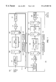
- FIG. 1 is a block diagram of a typical prior art multicarrier transceiver.
- FIG. 2 is a block diagram of a filter bank for performing the time-domain to frequency-domain transformation utilized by the present invention.
- FIG. 3 is a block diagram of a filter bank for performing the frequency-domain to time-domain transformation utilized by the present invention.
- FIG. 4 is a schematic view of a second embodiment of a synthesis filter bank that may be used with the present invention to generate a frequency-domain to time-domain transformation.
- FIG. 5 is a schematic view of a second embodiment of an analysis filter bank that may be used with the present invention to generate a time-domain to frequency-domain transformation.
- FIG. 1 is a block diagram of a typical prior art multi-carrier transceiver 100 .
- Transceiver 100 transmits data on a communication link 113 .
- the input data stream is received by a symbol generator 102 which converts a run of data bits from the input stream into M symbols S 1 , S 2 , . . . , S M which are stored in a register 104 .
- the number of possible states for each symbol will depend on the noise levels in the corresponding frequency band on the transmission channel 113 and on the error rate that can be tolerated by the data.
- each symbol is a number whose absolute value may vary from 0 to some predetermined upper bound. For example, if a symbol has 16 possible values, this symbol can be used to represent 4 bits in the input data stream.
- Transceiver 100 treats the symbols S i as if they were the amplitude of a signal in a narrow frequency band.
- Frequency to time-domain transform circuit 106 generates a time-domain signal X i , for i from 0 to M ⁇ 1, that has the frequency components S i .
- the time-domain signals are stored in a shift register 108 .
- the contents of shift register 108 represent, in digital form, the next segment of the signal that is to be actually transmitted over communication link 113 .
- the actual transmission is accomplished by clocking the digital values onto transmission link 113 (possibly after upconversion to radio frequencies) after converting the values to analog voltages using D/A converter 110 .
- Clock 107 provides the timing pulses for the operation.
- the output of D/A converter 110 is low-pass filtered by filter 112 before being placed on communication link 113 .
- the transmission segment is recovered.
- the signals received on communication link 113 are low-pass filtered to reduce the effects of high frequency noise transients.
- the signals are then digitized and shifted into a register 118 .
- M values have been shifted into register 118 , the contents thereof are converted via a time-domain to frequency-domain transform circuit 120 to generate a set of frequency-domain symbols S′ i .
- This transformation is the inverse of the transformation generated by frequency to time-domain transform 106 .
- communication link 113 will, in general, both attenuate and phase shift the signal represented by the X i .
- the signal values received at low-pass filter 114 and A/D converter 116 will differ from the original signal values.
- shift register 118 will not match the corresponding values from shift register 108 .
- the contents of shift register 118 are denoted by X′ i .
- the output of the time to frequency-domain transform will also differ from the original symbols S i ; hence, the contents of register 122 are denoted by S′ i .
- Equalizer 124 corrects the S′ i for the attenuation and phase shift resulting from transmission over communication link 113 to recover the original symbols which are stored in buffer 126 .
- equalizer 124 corrects the symbols for intersymbol interference arising from synchronization errors between the transmitter and receiver.
- the contents of buffer 126 are decoded to regenerate the original data stream by symbol decoder 128 .
- each subchannel must be sufficiently narrow to allow the distortions in that subchannel to be modeled by a single phase shift and attenuation.
- Sub-channels must also be sufficiently narrow to assure that a sub-channel that is turned off to prevent interference from narrow band sources does not unduly waste bandwith beyond that corrupted by the interference source.
- using narrower channels across the transmission band increases both system latency and the computational complexity of the frequency-domain-to-time-domain transformation and its inverse.
- the present invention is based on the observation that the variation in the attenuation and phase shift as a function of frequency is greater at low frequencies than at higher frequencies for communication links consisting of twisted pairs or coaxial cable.
- it is advantageous from a computational complexity viewpoint to employ narrower subchannels at the low frequencies and wider subchannels at the higher frequencies in a multicarrier modulation system.
- a transformation that breaks the available frequency band into sub-bands of differing width is required.
- Such a transformation may be constructed from a tree configured filter bank. Tree configured filters are known in the audio compression arts.
- U.S. Pat. No. 5,408,580 which is hereby incorporated by reference, describes the analysis of an audio signal into frequency components representing the audio signal in different frequency bands utilizing such a filter.
- the frequency bands vary in width such that the lower frequency bands are divided into smaller bands than the higher frequency bands.
- FIG. 2 illustrates the decomposition of a signal into frequency sub-bands by a tree structured filter 30 .
- Filter 30 includes two levels of filter banks. The manner in which the filter banks are constructed will be discussed in more detail below. In the example shown in FIG. 2, 22 sub-bands are utilized.
- the decomposition is carried out in two levels of filters.
- the first level of filter 30 consists of a filter bank 31 which divides the input signal into eight sub-bands of equal size.
- the second level subdivides the lowest three frequency bands from filter bank 31 into finer subdivisions.
- the second level consists of three filter banks 32 - 34 .
- Filter bank 32 divides the lowest sub-band from filter bank 31 into 8 equal sub-bands.
- Filter bank 33 and filter bank 34 divide the second and third sub-bands created by filter bank 31 into five and four sub-bands respectively. The combination of the two levels generates 22 frequency sub-bands.
- the analysis filter bank is used to demodulate the received signal.
- the filter bank performs a time-domain to frequency-domain transformation, converting received signal amplitudes into demodulated symbols for subsequent equalization.
- the reverse transformation can performed by an analogous filter bank such as shown in FIG. 3 at 60 .
- Filter 60 provides the frequency-domain to time-domain transformation shown in FIG. 1 .
- the reverse transformation also utilizes a two level tree structure.
- the symbols to be sent on the finer sub-bands are first combined using a first set of synthesis filters shown at 62 - 64 to provide signals representing three larger sub-bands of the same width as bands 18 - 22 . These “symbols” together with those from bands 18 - 22 are then combined by synthesis filter 61 to provide the time-domain output signal that is sent on the communication link.
- the filters may be implemented as finite impulse response filters with real filter coefficients. If the synthesis filter generates M coefficients per frame representing the amplitude of the transmitted signal, the filter bank accepts M frequency-domain symbols and generates M time-domain coefficients. However, it should be noted that the M coefficients generated may also depend on symbols received prior to the M frequency-domain symbols of the current frame. Similarly, the analysis filter bank demodulates M frequency-domain symbols from M time-domain received signal values in a given frame, and the resulting M symbols may depend on previous frames of M time-domain signal values processed by the filter bank.
- the communication bandwidth may alternatively be broken up into subbands of distinct (nonuniform) bandwidths by means of a single nonuniform filter bank transform.
- the synthesis filter bank, or frequency-domain-to-time-domain transform for converting symbols into signal values for transmission, is depicted in FIG. 4 at 300 for a system having K subchannels. If the subchannels are nonuniform in their bandwidth, distinct subchannels of the filter bank will operate at different upsampling rates, the upsampling rate of the k th subchannel will be denoted by M k .
- synthesis filter bank 300 generates M tot time-domain samples in each time frame.
- M tot is the least common multilple of the upsampling rates M k provided by the upsamplers of which 302 is typical.
- n k M tot M k . ( 2 )
- symbols from previous frames may contribute to the output of a given frame.
- Each of the contributions x k from the K distinct subchannels are added together, as shown at 301 , to produce a set of M tot time-domain signal values x[n] from M tot input symbols S k,i during the given frame.
- the k th subchannel will have a bandwidth that is 1/M k as large as that occupied by the full transmitted signal.
- the incoming discrete signal values x′[n] are passed through an analysis filter bank 400 , depicted in FIG. 5 .
- the received signal values are denoted by x′ to emphasize that the samples have been altered by the transmission link.
- Each filter in this bank has a characteristic downsampling ratio M k imposed after filtering by an finite impulse response filter, producing a set of M tot output symbols s per frame.
- a typical filter is shown at 401 with its corresponding downsampler at 402 .
- input signal values from preceding frames may contribute to the set of symbols output during a given frame.
- the subchannel waveforms, f k, together with the receive filters H k satisfy perfect-reconstruction or near-perfect-reconstruction conditions, with an output symbol stream that is identical (except for a possible delay of an integer number of samples) to the input symbol stream. This is equivalent to the absence of inter-symbol and inter-channel interference upon reconstruction.
- Methods for the design of such finite-impulse-response filter bank waveforms are known to the art. The reader is referred to J. Li, T. Q. Nguyen, S. Tantaratana, “A simple design method for nonuniform multirate filter banks,” in Proc. Asilomar Conf. On Signals, Systems, and Computers , November 1994 for a detailed discussion of such filter banks.
Abstract
Description


Claims (4)
Priority Applications (3)
| Application Number | Priority Date | Filing Date | Title |
|---|---|---|---|
| US08/804,909 US6252909B1 (en) | 1992-09-21 | 1997-02-25 | Multi-carrier transmission system utilizing channels of different bandwidth |
| US10/994,925 USRE40281E1 (en) | 1992-09-21 | 2004-11-23 | Signal processing utilizing a tree-structured array |
| US11/898,920 USRE42949E1 (en) | 1992-09-21 | 2007-09-14 | Stereophonic audio signal decompression switching to monaural audio signal |
Applications Claiming Priority (3)
| Application Number | Priority Date | Filing Date | Title |
|---|---|---|---|
| US07/948,147 US5408580A (en) | 1992-09-21 | 1992-09-21 | Audio compression system employing multi-rate signal analysis |
| US08/307,331 US5606642A (en) | 1992-09-21 | 1994-09-16 | Audio decompression system employing multi-rate signal analysis |
| US08/804,909 US6252909B1 (en) | 1992-09-21 | 1997-02-25 | Multi-carrier transmission system utilizing channels of different bandwidth |
Related Parent Applications (3)
| Application Number | Title | Priority Date | Filing Date |
|---|---|---|---|
| US08/307,331 Continuation-In-Part US5606642A (en) | 1992-09-21 | 1994-09-16 | Audio decompression system employing multi-rate signal analysis |
| US60383303A Division | 1992-09-21 | 2003-06-26 | |
| US10/994,925 Continuation USRE40281E1 (en) | 1992-09-21 | 2004-11-23 | Signal processing utilizing a tree-structured array |
Related Child Applications (2)
| Application Number | Title | Priority Date | Filing Date |
|---|---|---|---|
| US10/994,925 Reissue USRE40281E1 (en) | 1992-09-21 | 2004-11-23 | Signal processing utilizing a tree-structured array |
| US11/898,920 Reissue USRE42949E1 (en) | 1992-09-21 | 2007-09-14 | Stereophonic audio signal decompression switching to monaural audio signal |
Publications (1)
| Publication Number | Publication Date |
|---|---|
| US6252909B1 true US6252909B1 (en) | 2001-06-26 |
Family
ID=26975678
Family Applications (3)
| Application Number | Title | Priority Date | Filing Date |
|---|---|---|---|
| US08/804,909 Ceased US6252909B1 (en) | 1992-09-21 | 1997-02-25 | Multi-carrier transmission system utilizing channels of different bandwidth |
| US10/994,925 Expired - Lifetime USRE40281E1 (en) | 1992-09-21 | 2004-11-23 | Signal processing utilizing a tree-structured array |
| US11/898,920 Expired - Lifetime USRE42949E1 (en) | 1992-09-21 | 2007-09-14 | Stereophonic audio signal decompression switching to monaural audio signal |
Family Applications After (2)
| Application Number | Title | Priority Date | Filing Date |
|---|---|---|---|
| US10/994,925 Expired - Lifetime USRE40281E1 (en) | 1992-09-21 | 2004-11-23 | Signal processing utilizing a tree-structured array |
| US11/898,920 Expired - Lifetime USRE42949E1 (en) | 1992-09-21 | 2007-09-14 | Stereophonic audio signal decompression switching to monaural audio signal |
Country Status (1)
| Country | Link |
|---|---|
| US (3) | US6252909B1 (en) |
Cited By (41)
| Publication number | Priority date | Publication date | Assignee | Title |
|---|---|---|---|---|
| US20020010488A1 (en) * | 2000-06-16 | 2002-01-24 | Crawford Lynn D. | Balloon occlusion device having a proximal valve |
| US6459832B1 (en) * | 2000-11-28 | 2002-10-01 | Nortel Networks Limited | Method and apparatus for optical signal transmission using multiple sub-signals of non-uniform bandwidth |
| US6496546B1 (en) * | 1998-07-15 | 2002-12-17 | Lucent Technologies Inc. | Software-defined transceiver for a wireless telecommunications system |
| US20030099299A1 (en) * | 2001-09-26 | 2003-05-29 | Rogerson Gerald D. | Method and apparatus for data transfer using a time division multiple frequency scheme |
| US20030202537A1 (en) * | 2001-09-26 | 2003-10-30 | General Atomics | Method and apparatus for data transfer using a time division multiple frequency scheme supplemented with polarity modulation |
| US20040008729A1 (en) * | 2001-09-26 | 2004-01-15 | General Atomics | Method and apparatus for data transfer using a time division multiple frequency scheme with additional modulation |
| US20040028012A1 (en) * | 2001-09-26 | 2004-02-12 | General Atomics | Flexible method and apparatus for encoding and decoding signals using a time division multiple frequency scheme |
| US20040028011A1 (en) * | 2001-09-26 | 2004-02-12 | General Atomics | Method and apparatus for adapting signaling to maximize the efficiency of spectrum usage for multi-band systems in the presence of interference |
| US20040048574A1 (en) * | 2001-09-26 | 2004-03-11 | General Atomics | Method and apparatus for adapting multi-band ultra-wideband signaling to interference sources |
| US20040165737A1 (en) * | 2001-03-30 | 2004-08-26 | Monro Donald Martin | Audio compression |
| US20040203709A1 (en) * | 2002-11-08 | 2004-10-14 | Louis Luneau | Flexible software radio transceiver |
| US20050099728A1 (en) * | 2003-11-10 | 2005-05-12 | Matsushita Electric Industrial Co. | Disk drive, head slider, and head supporting device |
| US6937969B1 (en) * | 1999-06-10 | 2005-08-30 | Interuniversitair Microelektronica Centrum (Imec) | Method for determining signals in mixed signal systems |
| US7010048B1 (en) * | 1998-02-12 | 2006-03-07 | Aqvity, Llc | Multiple access method and system |
| US20060115012A1 (en) * | 2004-12-01 | 2006-06-01 | John Sadowsky | Increased discrete point processing in an OFDM communication system |
| WO2006128973A1 (en) * | 2005-06-03 | 2006-12-07 | Nokia Siemens Networks Oy | Receiver, transmitter and variable bandwidth transmission method |
| US7177353B2 (en) * | 2000-03-10 | 2007-02-13 | Broadcom Corporation | Architecture for very high-speed decision feedback sequence estimation |
| US7609611B1 (en) * | 1999-09-29 | 2009-10-27 | France Telecom | Method for transmitting an offset modulated biorthogonal multicarrier signal (BFDM/OM) |
| USRE42949E1 (en) * | 1992-09-21 | 2011-11-22 | Hybrid Audio Llc | Stereophonic audio signal decompression switching to monaural audio signal |
| US20130107766A1 (en) * | 2007-05-14 | 2013-05-02 | Kamran Etemad | Multicarrier techniques for wireless systems |
| USRE45293E1 (en) * | 1997-09-04 | 2014-12-16 | Sony Deutschland Gmbh | Transmission system for OFDM-signals with optimized synchronization |
| US20150304144A1 (en) * | 2012-11-19 | 2015-10-22 | Orange | Method for determining at least one filter of a filter bank of a transmission or coding system, corresponding device and computer program |
| US9485063B2 (en) | 2001-04-26 | 2016-11-01 | Genghiscomm Holdings, LLC | Pre-coding in multi-user MIMO |
| US9628231B2 (en) | 2002-05-14 | 2017-04-18 | Genghiscomm Holdings, LLC | Spreading and precoding in OFDM |
| GB2557209A (en) * | 2016-11-30 | 2018-06-20 | Univ Surrey | Multi-rate wireless communication network |
| US10142082B1 (en) | 2002-05-14 | 2018-11-27 | Genghiscomm Holdings, LLC | Pre-coding in OFDM |
| US10200227B2 (en) | 2002-05-14 | 2019-02-05 | Genghiscomm Holdings, LLC | Pre-coding in multi-user MIMO |
| US10305636B1 (en) | 2004-08-02 | 2019-05-28 | Genghiscomm Holdings, LLC | Cooperative MIMO |
| US10644916B1 (en) | 2002-05-14 | 2020-05-05 | Genghiscomm Holdings, LLC | Spreading and precoding in OFDM |
| US10797732B1 (en) | 2001-04-26 | 2020-10-06 | Genghiscomm Holdings, LLC | Distributed antenna systems |
| US10880145B2 (en) | 2019-01-25 | 2020-12-29 | Genghiscomm Holdings, LLC | Orthogonal multiple access and non-orthogonal multiple access |
| US10931338B2 (en) | 2001-04-26 | 2021-02-23 | Genghiscomm Holdings, LLC | Coordinated multipoint systems |
| US11018918B1 (en) | 2017-05-25 | 2021-05-25 | Genghiscomm Holdings, LLC | Peak-to-average-power reduction for OFDM multiple access |
| US11115160B2 (en) | 2019-05-26 | 2021-09-07 | Genghiscomm Holdings, LLC | Non-orthogonal multiple access |
| US11184037B1 (en) | 2004-08-02 | 2021-11-23 | Genghiscomm Holdings, LLC | Demodulating and decoding carrier interferometry signals |
| US11196603B2 (en) | 2017-06-30 | 2021-12-07 | Genghiscomm Holdings, LLC | Efficient synthesis and analysis of OFDM and MIMO-OFDM signals |
| US11343823B2 (en) | 2020-08-16 | 2022-05-24 | Tybalt, Llc | Orthogonal multiple access and non-orthogonal multiple access |
| US11381285B1 (en) | 2004-08-02 | 2022-07-05 | Genghiscomm Holdings, LLC | Transmit pre-coding |
| US11552737B1 (en) | 2004-08-02 | 2023-01-10 | Genghiscomm Holdings, LLC | Cooperative MIMO |
| US11916624B2 (en) | 2021-12-15 | 2024-02-27 | Nxp Usa, Inc. | System and method for enabling multi-user multiple-input-multiple-output communication in wireless networks |
| US11917604B2 (en) | 2019-01-25 | 2024-02-27 | Tybalt, Llc | Orthogonal multiple access and non-orthogonal multiple access |
Families Citing this family (11)
| Publication number | Priority date | Publication date | Assignee | Title |
|---|---|---|---|---|
| US7783456B2 (en) * | 2003-03-19 | 2010-08-24 | Advantest Corporation | Wave detection device, method, program, and recording medium |
| EP1475996B1 (en) * | 2003-05-06 | 2009-04-08 | Harman Becker Automotive Systems GmbH | Stereo audio-signal processing system |
| EP1722360B1 (en) * | 2005-05-13 | 2014-03-19 | Harman Becker Automotive Systems GmbH | Audio enhancement system and method |
| DK2337224T3 (en) * | 2006-07-04 | 2017-10-02 | Dolby Int Ab | Filter unit and method for generating subband filter pulse response |
| US8219871B2 (en) * | 2008-03-18 | 2012-07-10 | Nec Laboratories America, Inc. | Efficient decoupling schemes for quantum systems using soft pulses |
| KR101517446B1 (en) | 2010-08-12 | 2015-05-04 | 프라운호퍼 게젤샤프트 쭈르 푀르데룽 데어 안겐반텐 포르슝 에. 베. | Resampling output signals of qmf based audio codecs |
| EP2904786B1 (en) | 2012-10-01 | 2018-12-05 | GE Video Compression, LLC | Scalable video coding using inter-layer prediction of spatial intra prediction parameters |
| EP3039836A1 (en) * | 2013-08-29 | 2016-07-06 | Interdigital Patent Holdings, Inc. | Methods and apparatus for faster than nyquist rate multi-carrier modulation |
| US10748551B2 (en) * | 2014-07-16 | 2020-08-18 | Nec Corporation | Noise suppression system, noise suppression method, and recording medium storing program |
| CN110149118A (en) * | 2019-04-28 | 2019-08-20 | 北京航空航天大学 | A kind of dynamic channelization method based on non-homogeneous filter group |
| US11682406B2 (en) * | 2021-01-28 | 2023-06-20 | Sony Interactive Entertainment LLC | Level-of-detail audio codec |
Citations (5)
| Publication number | Priority date | Publication date | Assignee | Title |
|---|---|---|---|---|
| US5048054A (en) * | 1989-05-12 | 1991-09-10 | Codex Corporation | Line probing modem |
| US5170413A (en) * | 1990-12-24 | 1992-12-08 | Motorola, Inc. | Control strategy for reuse system assignments and handoff |
| US5243629A (en) * | 1991-09-03 | 1993-09-07 | At&T Bell Laboratories | Multi-subcarrier modulation for hdtv transmission |
| US5285474A (en) * | 1992-06-12 | 1994-02-08 | The Board Of Trustees Of The Leland Stanford, Junior University | Method for equalizing a multicarrier signal in a multicarrier communication system |
| US5479447A (en) * | 1993-05-03 | 1995-12-26 | The Board Of Trustees Of The Leland Stanford, Junior University | Method and apparatus for adaptive, variable bandwidth, high-speed data transmission of a multicarrier signal over digital subscriber lines |
Family Cites Families (34)
| Publication number | Priority date | Publication date | Assignee | Title |
|---|---|---|---|---|
| US3947827A (en) * | 1974-05-29 | 1976-03-30 | Whittaker Corporation | Digital storage system for high frequency signals |
| US3976863A (en) * | 1974-07-01 | 1976-08-24 | Alfred Engel | Optimal decoder for non-stationary signals |
| JPS539403A (en) * | 1976-07-14 | 1978-01-27 | Pioneer Electronic Corp | Fm stereophonic receiver |
| FR2412987A1 (en) * | 1977-12-23 | 1979-07-20 | Ibm France | PROCESS FOR COMPRESSION OF DATA RELATING TO THE VOICE SIGNAL AND DEVICE IMPLEMENTING THIS PROCEDURE |
| JPS6122366Y2 (en) * | 1978-07-28 | 1986-07-04 | ||
| JPS5854692B2 (en) * | 1979-12-28 | 1983-12-06 | 三洋電機株式会社 | stereo multiplex circuit |
| US4479235A (en) * | 1981-05-08 | 1984-10-23 | Rca Corporation | Switching arrangement for a stereophonic sound synthesizer |
| CA1253255A (en) * | 1983-05-16 | 1989-04-25 | Nec Corporation | System for simultaneously coding and decoding a plurality of signals |
| GB8421498D0 (en) * | 1984-08-24 | 1984-09-26 | British Telecomm | Frequency domain speech coding |
| US4622680A (en) * | 1984-10-17 | 1986-11-11 | General Electric Company | Hybrid subband coder/decoder method and apparatus |
| FR2577084B1 (en) * | 1985-02-01 | 1987-03-20 | Trt Telecom Radio Electr | BENCH SYSTEM OF SIGNAL ANALYSIS AND SYNTHESIS FILTERS |
| DE3510573A1 (en) * | 1985-03-23 | 1986-09-25 | Philips Patentverwaltung | DIGITAL ANALYSIS SYNTHESIS FILTER BANK WITH MAXIMUM CYCLE REDUCTION |
| US4747142A (en) * | 1985-07-25 | 1988-05-24 | Tofte David A | Three-track sterophonic system |
| US4653095A (en) * | 1986-02-06 | 1987-03-24 | Kahn Leonard R | AM stereo receivers having platform motion protection |
| DE3639753A1 (en) * | 1986-11-21 | 1988-06-01 | Inst Rundfunktechnik Gmbh | METHOD FOR TRANSMITTING DIGITALIZED SOUND SIGNALS |
| US4833715A (en) * | 1987-03-06 | 1989-05-23 | Alps Electric Co., Ltd. | FM stereo receiver |
| NL8700985A (en) * | 1987-04-27 | 1988-11-16 | Philips Nv | SYSTEM FOR SUB-BAND CODING OF A DIGITAL AUDIO SIGNAL. |
| US4815023A (en) * | 1987-05-04 | 1989-03-21 | General Electric Company | Quadrature mirror filters with staggered-phase subsampling |
| US4882754A (en) * | 1987-08-25 | 1989-11-21 | Digideck, Inc. | Data compression system and method with buffer control |
| US4852179A (en) * | 1987-10-05 | 1989-07-25 | Motorola, Inc. | Variable frame rate, fixed bit rate vocoding method |
| US5225904A (en) * | 1987-10-05 | 1993-07-06 | Intel Corporation | Adaptive digital video compression system |
| US4829378A (en) * | 1988-06-09 | 1989-05-09 | Bell Communications Research, Inc. | Sub-band coding of images with low computational complexity |
| US4918524A (en) * | 1989-03-14 | 1990-04-17 | Bell Communications Research, Inc. | HDTV Sub-band coding using IIR filter bank |
| EP0400222A1 (en) * | 1989-06-02 | 1990-12-05 | ETAT FRANCAIS représenté par le Ministère des Postes, des Télécommunications et de l'Espace | Digital transmission system using subband coding of a digital signal |
| DE3922469A1 (en) * | 1989-07-07 | 1991-01-17 | Nixdorf Computer Ag | METHOD FOR FILTERING DIGITIZED SIGNALS |
| SG49883A1 (en) * | 1991-01-08 | 1998-06-15 | Dolby Lab Licensing Corp | Encoder/decoder for multidimensional sound fields |
| KR950008635B1 (en) * | 1992-02-27 | 1995-08-03 | 삼성전자주식회사 | Mono channel setting circuit in stereo exclusive use audio system |
| US5285498A (en) * | 1992-03-02 | 1994-02-08 | At&T Bell Laboratories | Method and apparatus for coding audio signals based on perceptual model |
| US5408580A (en) * | 1992-09-21 | 1995-04-18 | Aware, Inc. | Audio compression system employing multi-rate signal analysis |
| US6252909B1 (en) * | 1992-09-21 | 2001-06-26 | Aware, Inc. | Multi-carrier transmission system utilizing channels of different bandwidth |
| JPH06318885A (en) * | 1993-03-11 | 1994-11-15 | Nec Corp | Unknown system identifying method/device using band division adaptive filter |
| JPH0865799A (en) * | 1994-02-25 | 1996-03-08 | Sony Electron Inc | Mono/stereo changeover circuit |
| DE19542738A1 (en) * | 1995-11-16 | 1997-05-22 | Bayerische Motoren Werke Ag | Switching arrangement for mobile radio receivers |
| DE19542737A1 (en) * | 1995-11-16 | 1997-05-22 | Bayerische Motoren Werke Ag | Switching arrangement for mobile radio receivers |
-
1997
- 1997-02-25 US US08/804,909 patent/US6252909B1/en not_active Ceased
-
2004
- 2004-11-23 US US10/994,925 patent/USRE40281E1/en not_active Expired - Lifetime
-
2007
- 2007-09-14 US US11/898,920 patent/USRE42949E1/en not_active Expired - Lifetime
Patent Citations (5)
| Publication number | Priority date | Publication date | Assignee | Title |
|---|---|---|---|---|
| US5048054A (en) * | 1989-05-12 | 1991-09-10 | Codex Corporation | Line probing modem |
| US5170413A (en) * | 1990-12-24 | 1992-12-08 | Motorola, Inc. | Control strategy for reuse system assignments and handoff |
| US5243629A (en) * | 1991-09-03 | 1993-09-07 | At&T Bell Laboratories | Multi-subcarrier modulation for hdtv transmission |
| US5285474A (en) * | 1992-06-12 | 1994-02-08 | The Board Of Trustees Of The Leland Stanford, Junior University | Method for equalizing a multicarrier signal in a multicarrier communication system |
| US5479447A (en) * | 1993-05-03 | 1995-12-26 | The Board Of Trustees Of The Leland Stanford, Junior University | Method and apparatus for adaptive, variable bandwidth, high-speed data transmission of a multicarrier signal over digital subscriber lines |
Cited By (96)
| Publication number | Priority date | Publication date | Assignee | Title |
|---|---|---|---|---|
| USRE42949E1 (en) * | 1992-09-21 | 2011-11-22 | Hybrid Audio Llc | Stereophonic audio signal decompression switching to monaural audio signal |
| USRE45293E1 (en) * | 1997-09-04 | 2014-12-16 | Sony Deutschland Gmbh | Transmission system for OFDM-signals with optimized synchronization |
| US7010048B1 (en) * | 1998-02-12 | 2006-03-07 | Aqvity, Llc | Multiple access method and system |
| US6496546B1 (en) * | 1998-07-15 | 2002-12-17 | Lucent Technologies Inc. | Software-defined transceiver for a wireless telecommunications system |
| US6937969B1 (en) * | 1999-06-10 | 2005-08-30 | Interuniversitair Microelektronica Centrum (Imec) | Method for determining signals in mixed signal systems |
| US7609611B1 (en) * | 1999-09-29 | 2009-10-27 | France Telecom | Method for transmitting an offset modulated biorthogonal multicarrier signal (BFDM/OM) |
| US7738549B2 (en) | 2000-03-10 | 2010-06-15 | Broadcom Corporation | Architecture for very high-speed decision feedback sequence estimation |
| US20100303144A1 (en) * | 2000-03-10 | 2010-12-02 | Arthur Abnous | Architecture for very high-speed decision feedback sequence estimation |
| US20070189376A1 (en) * | 2000-03-10 | 2007-08-16 | Arthur Abnous | Architecture for very high-speed decision feedback sequence estimation |
| US7177353B2 (en) * | 2000-03-10 | 2007-02-13 | Broadcom Corporation | Architecture for very high-speed decision feedback sequence estimation |
| US8934527B2 (en) | 2000-03-10 | 2015-01-13 | Broadcom Corporation | Architecture for very high-speed decision feedback sequence estimation |
| US20020010488A1 (en) * | 2000-06-16 | 2002-01-24 | Crawford Lynn D. | Balloon occlusion device having a proximal valve |
| US6923822B2 (en) | 2000-06-16 | 2005-08-02 | Abbott Laboratories | Balloon occlusion device having a proximal valve |
| US6459832B1 (en) * | 2000-11-28 | 2002-10-01 | Nortel Networks Limited | Method and apparatus for optical signal transmission using multiple sub-signals of non-uniform bandwidth |
| US20040165737A1 (en) * | 2001-03-30 | 2004-08-26 | Monro Donald Martin | Audio compression |
| US10797732B1 (en) | 2001-04-26 | 2020-10-06 | Genghiscomm Holdings, LLC | Distributed antenna systems |
| US11424792B2 (en) | 2001-04-26 | 2022-08-23 | Genghiscomm Holdings, LLC | Coordinated multipoint systems |
| US10797733B1 (en) | 2001-04-26 | 2020-10-06 | Genghiscomm Holdings, LLC | Distributed antenna systems |
| US9485063B2 (en) | 2001-04-26 | 2016-11-01 | Genghiscomm Holdings, LLC | Pre-coding in multi-user MIMO |
| US10931338B2 (en) | 2001-04-26 | 2021-02-23 | Genghiscomm Holdings, LLC | Coordinated multipoint systems |
| US7403575B2 (en) | 2001-09-26 | 2008-07-22 | General Atomics | Method and apparatus for adapting signaling to maximize the efficiency of spectrum usage for multi-band systems in the presence of interference |
| US7436899B2 (en) | 2001-09-26 | 2008-10-14 | General Atomics | Method and apparatus for data transfer using wideband bursts |
| US20040048574A1 (en) * | 2001-09-26 | 2004-03-11 | General Atomics | Method and apparatus for adapting multi-band ultra-wideband signaling to interference sources |
| US7321601B2 (en) | 2001-09-26 | 2008-01-22 | General Atomics | Method and apparatus for data transfer using a time division multiple frequency scheme supplemented with polarity modulation |
| US7342973B2 (en) | 2001-09-26 | 2008-03-11 | General Atomics | Method and apparatus for adapting multi-band ultra-wideband signaling to interference sources |
| US20080130685A1 (en) * | 2001-09-26 | 2008-06-05 | General Atomics | Method and Apparatus for Data Transfer Using a Time Division Multiple Frequency Scheme Supplemented with Polarity Modulation |
| US20050232371A1 (en) * | 2001-09-26 | 2005-10-20 | General Atomics | Method and apparatus for data transfer using wideband bursts |
| US7236464B2 (en) | 2001-09-26 | 2007-06-26 | General Atomics | Flexible method and apparatus for encoding and decoding signals using a time division multiple frequency scheme |
| US7609608B2 (en) | 2001-09-26 | 2009-10-27 | General Atomics | Method and apparatus for data transfer using a time division multiple frequency scheme with additional modulation |
| US20040028011A1 (en) * | 2001-09-26 | 2004-02-12 | General Atomics | Method and apparatus for adapting signaling to maximize the efficiency of spectrum usage for multi-band systems in the presence of interference |
| US20040028012A1 (en) * | 2001-09-26 | 2004-02-12 | General Atomics | Flexible method and apparatus for encoding and decoding signals using a time division multiple frequency scheme |
| US20040008729A1 (en) * | 2001-09-26 | 2004-01-15 | General Atomics | Method and apparatus for data transfer using a time division multiple frequency scheme with additional modulation |
| US6895059B2 (en) | 2001-09-26 | 2005-05-17 | General Atomics | Method and apparatus for data transfer using a time division multiple frequency scheme |
| US20030202537A1 (en) * | 2001-09-26 | 2003-10-30 | General Atomics | Method and apparatus for data transfer using a time division multiple frequency scheme supplemented with polarity modulation |
| US8149879B2 (en) | 2001-09-26 | 2012-04-03 | General Atomics | Method and apparatus for data transfer using a time division multiple frequency scheme supplemented with polarity modulation |
| US20030099299A1 (en) * | 2001-09-26 | 2003-05-29 | Rogerson Gerald D. | Method and apparatus for data transfer using a time division multiple frequency scheme |
| US10015034B1 (en) | 2002-05-14 | 2018-07-03 | Genghiscomm Holdings, LLC | Spreading and precoding in OFDM |
| US10903970B1 (en) | 2002-05-14 | 2021-01-26 | Genghiscomm Holdings, LLC | Pre-coding in OFDM |
| US11025312B2 (en) | 2002-05-14 | 2021-06-01 | Genghiscomm Holdings, LLC | Blind-adaptive decoding of radio signals |
| US11025468B1 (en) | 2002-05-14 | 2021-06-01 | Genghiscomm Holdings, LLC | Single carrier frequency division multiple access baseband signal generation |
| US10840978B2 (en) | 2002-05-14 | 2020-11-17 | Genghiscomm Holdings, LLC | Cooperative wireless networks |
| US10778492B1 (en) | 2002-05-14 | 2020-09-15 | Genghiscomm Holdings, LLC | Single carrier frequency division multiple access baseband signal generation |
| US9628231B2 (en) | 2002-05-14 | 2017-04-18 | Genghiscomm Holdings, LLC | Spreading and precoding in OFDM |
| US10644916B1 (en) | 2002-05-14 | 2020-05-05 | Genghiscomm Holdings, LLC | Spreading and precoding in OFDM |
| US9768842B2 (en) | 2002-05-14 | 2017-09-19 | Genghiscomm Holdings, LLC | Pre-coding in multi-user MIMO |
| US9800448B1 (en) | 2002-05-14 | 2017-10-24 | Genghiscomm Holdings, LLC | Spreading and precoding in OFDM |
| US9967007B2 (en) | 2002-05-14 | 2018-05-08 | Genghiscomm Holdings, LLC | Cooperative wireless networks |
| US10587369B1 (en) | 2002-05-14 | 2020-03-10 | Genghiscomm Holdings, LLC | Cooperative subspace multiplexing |
| US10009208B1 (en) | 2002-05-14 | 2018-06-26 | Genghiscomm Holdings, LLC | Spreading and precoding in OFDM |
| US10574497B1 (en) | 2002-05-14 | 2020-02-25 | Genghiscomm Holdings, LLC | Spreading and precoding in OFDM |
| US10038584B1 (en) | 2002-05-14 | 2018-07-31 | Genghiscomm Holdings, LLC | Spreading and precoding in OFDM |
| US10142082B1 (en) | 2002-05-14 | 2018-11-27 | Genghiscomm Holdings, LLC | Pre-coding in OFDM |
| US10200227B2 (en) | 2002-05-14 | 2019-02-05 | Genghiscomm Holdings, LLC | Pre-coding in multi-user MIMO |
| US10211892B2 (en) | 2002-05-14 | 2019-02-19 | Genghiscomm Holdings, LLC | Spread-OFDM receiver |
| US10230559B1 (en) | 2002-05-14 | 2019-03-12 | Genghiscomm Holdings, LLC | Spreading and precoding in OFDM |
| US10389568B1 (en) | 2002-05-14 | 2019-08-20 | Genghiscomm Holdings, LLC | Single carrier frequency division multiple access baseband signal generation |
| US20040203709A1 (en) * | 2002-11-08 | 2004-10-14 | Louis Luneau | Flexible software radio transceiver |
| US7203488B2 (en) * | 2002-11-08 | 2007-04-10 | Louis Luneau | Flexible software radio transceiver |
| US20050099728A1 (en) * | 2003-11-10 | 2005-05-12 | Matsushita Electric Industrial Co. | Disk drive, head slider, and head supporting device |
| US11575555B2 (en) | 2004-08-02 | 2023-02-07 | Genghiscomm Holdings, LLC | Carrier interferometry transmitter |
| US11646929B1 (en) | 2004-08-02 | 2023-05-09 | Genghiscomm Holdings, LLC | Spreading and precoding in OFDM |
| US11252005B1 (en) | 2004-08-02 | 2022-02-15 | Genghiscomm Holdings, LLC | Spreading and precoding in OFDM |
| US11252006B1 (en) | 2004-08-02 | 2022-02-15 | Genghiscomm Holdings, LLC | Wireless communications using flexible channel bandwidth |
| US11804882B1 (en) | 2004-08-02 | 2023-10-31 | Genghiscomm Holdings, LLC | Single carrier frequency division multiple access baseband signal generation |
| US11784686B2 (en) | 2004-08-02 | 2023-10-10 | Genghiscomm Holdings, LLC | Carrier interferometry transmitter |
| US11671299B1 (en) | 2004-08-02 | 2023-06-06 | Genghiscomm Holdings, LLC | Wireless communications using flexible channel bandwidth |
| US10305636B1 (en) | 2004-08-02 | 2019-05-28 | Genghiscomm Holdings, LLC | Cooperative MIMO |
| US11552737B1 (en) | 2004-08-02 | 2023-01-10 | Genghiscomm Holdings, LLC | Cooperative MIMO |
| US11431386B1 (en) | 2004-08-02 | 2022-08-30 | Genghiscomm Holdings, LLC | Transmit pre-coding |
| US11018917B1 (en) | 2004-08-02 | 2021-05-25 | Genghiscomm Holdings, LLC | Spreading and precoding in OFDM |
| US11381285B1 (en) | 2004-08-02 | 2022-07-05 | Genghiscomm Holdings, LLC | Transmit pre-coding |
| US11223508B1 (en) | 2004-08-02 | 2022-01-11 | Genghiscomm Holdings, LLC | Wireless communications using flexible channel bandwidth |
| US11075786B1 (en) | 2004-08-02 | 2021-07-27 | Genghiscomm Holdings, LLC | Multicarrier sub-layer for direct sequence channel and multiple-access coding |
| US11184037B1 (en) | 2004-08-02 | 2021-11-23 | Genghiscomm Holdings, LLC | Demodulating and decoding carrier interferometry signals |
| US20060115012A1 (en) * | 2004-12-01 | 2006-06-01 | John Sadowsky | Increased discrete point processing in an OFDM communication system |
| US7881390B2 (en) * | 2004-12-01 | 2011-02-01 | Intel Corporation | Increased discrete point processing in an OFDM communication system |
| WO2006128973A1 (en) * | 2005-06-03 | 2006-12-07 | Nokia Siemens Networks Oy | Receiver, transmitter and variable bandwidth transmission method |
| US10512082B2 (en) * | 2007-05-14 | 2019-12-17 | Intel Corporation | Multicarrier techniques for wireless systems |
| US9497762B2 (en) * | 2007-05-14 | 2016-11-15 | Intel Corporation | Multicarrier techniques for wireless systems |
| US20170127418A1 (en) * | 2007-05-14 | 2017-05-04 | Intel Corporation | Multicarrier techniques for wireless systems |
| US20130107766A1 (en) * | 2007-05-14 | 2013-05-02 | Kamran Etemad | Multicarrier techniques for wireless systems |
| US20150304144A1 (en) * | 2012-11-19 | 2015-10-22 | Orange | Method for determining at least one filter of a filter bank of a transmission or coding system, corresponding device and computer program |
| US9621394B2 (en) * | 2012-11-19 | 2017-04-11 | Orange | Method for determining at least one filter of a filter bank of a transmission or coding system, corresponding device and computer program |
| GB2557209A (en) * | 2016-11-30 | 2018-06-20 | Univ Surrey | Multi-rate wireless communication network |
| GB2557209B (en) * | 2016-11-30 | 2022-04-13 | Univ Surrey | Multi-rate wireless communication network |
| US11894965B2 (en) | 2017-05-25 | 2024-02-06 | Tybalt, Llc | Efficient synthesis and analysis of OFDM and MIMO-OFDM signals |
| US11018918B1 (en) | 2017-05-25 | 2021-05-25 | Genghiscomm Holdings, LLC | Peak-to-average-power reduction for OFDM multiple access |
| US11700162B2 (en) | 2017-05-25 | 2023-07-11 | Tybalt, Llc | Peak-to-average-power reduction for OFDM multiple access |
| US11196603B2 (en) | 2017-06-30 | 2021-12-07 | Genghiscomm Holdings, LLC | Efficient synthesis and analysis of OFDM and MIMO-OFDM signals |
| US11570029B2 (en) | 2017-06-30 | 2023-01-31 | Tybalt Llc | Efficient synthesis and analysis of OFDM and MIMO-OFDM signals |
| US11917604B2 (en) | 2019-01-25 | 2024-02-27 | Tybalt, Llc | Orthogonal multiple access and non-orthogonal multiple access |
| US10880145B2 (en) | 2019-01-25 | 2020-12-29 | Genghiscomm Holdings, LLC | Orthogonal multiple access and non-orthogonal multiple access |
| US11791953B2 (en) | 2019-05-26 | 2023-10-17 | Tybalt, Llc | Non-orthogonal multiple access |
| US11115160B2 (en) | 2019-05-26 | 2021-09-07 | Genghiscomm Holdings, LLC | Non-orthogonal multiple access |
| US11343823B2 (en) | 2020-08-16 | 2022-05-24 | Tybalt, Llc | Orthogonal multiple access and non-orthogonal multiple access |
| US11916624B2 (en) | 2021-12-15 | 2024-02-27 | Nxp Usa, Inc. | System and method for enabling multi-user multiple-input-multiple-output communication in wireless networks |
Also Published As
| Publication number | Publication date |
|---|---|
| USRE42949E1 (en) | 2011-11-22 |
| USRE40281E1 (en) | 2008-04-29 |
Similar Documents
| Publication | Publication Date | Title |
|---|---|---|
| US6252909B1 (en) | Multi-carrier transmission system utilizing channels of different bandwidth | |
| US6456657B1 (en) | Frequency division multiplexed transmission of sub-band signals | |
| US5497398A (en) | Multi-carrier transceiver | |
| US5636246A (en) | Multicarrier transmission system | |
| US5715280A (en) | Method for partially modulating and demodulating data in a multi-carrier transmission system | |
| US6845082B2 (en) | Peak to average power ratio reduction in communication systems | |
| US5631610A (en) | Single side-band modulation system for use in digitally implemented multicarrier transmission systems | |
| JPH08501195A (en) | Digital signal transmission system using frequency division multiplexing. | |
| JPH10215237A (en) | Multiplex device/system for discrete time signal | |
| JP3630688B2 (en) | Digital transmission system | |
| US7443917B2 (en) | Method and system for transmission of information data over a communication line | |
| RU2298877C2 (en) | Method and device for pulse overlap compensation in digital-modulation signals | |
| US7609611B1 (en) | Method for transmitting an offset modulated biorthogonal multicarrier signal (BFDM/OM) | |
| US5832030A (en) | Multi-carrier transmission system utilizing channels with different error rates | |
| US7463678B2 (en) | Equalization scheme for DSL receivers in presence of an under-sampled or over-sampled transmit IDFT | |
| EP1802064B1 (en) | OFDM coding using Hermite polynomials | |
| US6987812B1 (en) | Digital receiver for a signal generated with discrete multi-tone modulation | |
| US7072412B1 (en) | Multicarrier digital transmission system using an OQAM transmultiplexer | |
| JP3940415B2 (en) | Multi-carrier communication system and communication method | |
| Leus et al. | Block transmission over multi-scale multi-lag wireless channels | |
| AU708318B2 (en) | Improved multicarrier transmission system | |
| Chen et al. | Zero forcing cosine modulated filterbank transceivers with cyclic prefix | |
| WO1999012317A1 (en) | Digital transmission using subband coding | |
| WO1998053572A1 (en) | Improved method for partially modulating and demodulating data in a multi-carrier transmission system | |
| Daneshgaran et al. | Performance of wavelet-based shaping pulses on linear and nonlinear channels |
Legal Events
| Date | Code | Title | Description |
|---|---|---|---|
| AS | Assignment |
Owner name: AWARE, INC., MASSACHUSETTS Free format text: ASSIGNMENT OF ASSIGNORS INTEREST;ASSIGNORS:TZANNES, MICHAEL;HELLER, PETER NIELS;REEL/FRAME:010913/0057 Effective date: 20000406 |
|
| AS | Assignment |
Owner name: AWARE, INC., MASSACHUSETTS Free format text: EMPLOYEE AGREEMENT;ASSIGNORS:JAYASIMHA, SRIRAM;MORRELL, WILLIAM;STAUTNER, JOHN;REEL/FRAME:011011/0755;SIGNING DATES FROM 19900730 TO 19911007 |
|
| STCF | Information on status: patent grant |
Free format text: PATENTED CASE |
|
| RF | Reissue application filed |
Effective date: 20030626 |
|
| FPAY | Fee payment |
Year of fee payment: 4 |
|
| RF | Reissue application filed |
Effective date: 20041123 |
|
| RF | Reissue application filed |
Effective date: 20070914 |
|
| REMI | Maintenance fee reminder mailed | ||
| FPAY | Fee payment |
Year of fee payment: 8 |
|
| SULP | Surcharge for late payment |
Year of fee payment: 7 |
|
| AS | Assignment |
Owner name: HYBRID AUDIO LLC, TEXAS Free format text: ASSIGNMENT OF ASSIGNORS INTEREST;ASSIGNOR:AWARE, INC.;REEL/FRAME:025534/0671 Effective date: 20101210 |
|
| AS | Assignment |
Owner name: HYBRID AUDIO, LLC., VIRGINIA Free format text: ASSIGNMENT OF ASSIGNORS INTEREST;ASSIGNOR:HYBRID AUDIO, LLC.;REEL/FRAME:038115/0877 Effective date: 20160328 |