US6205565B1 - Fault resilient/fault tolerant computing - Google Patents
Fault resilient/fault tolerant computing Download PDFInfo
- Publication number
- US6205565B1 US6205565B1 US09/081,074 US8107498A US6205565B1 US 6205565 B1 US6205565 B1 US 6205565B1 US 8107498 A US8107498 A US 8107498A US 6205565 B1 US6205565 B1 US 6205565B1
- Authority
- US
- United States
- Prior art keywords
- error
- iop
- elements
- reporting
- message
- Prior art date
- Legal status (The legal status is an assumption and is not a legal conclusion. Google has not performed a legal analysis and makes no representation as to the accuracy of the status listed.)
- Expired - Lifetime
Links
Images


Classifications
-
- G—PHYSICS
- G06—COMPUTING; CALCULATING OR COUNTING
- G06F—ELECTRIC DIGITAL DATA PROCESSING
- G06F11/00—Error detection; Error correction; Monitoring
- G06F11/07—Responding to the occurrence of a fault, e.g. fault tolerance
- G06F11/16—Error detection or correction of the data by redundancy in hardware
- G06F11/1629—Error detection by comparing the output of redundant processing systems
- G06F11/1641—Error detection by comparing the output of redundant processing systems where the comparison is not performed by the redundant processing components
-
- G—PHYSICS
- G06—COMPUTING; CALCULATING OR COUNTING
- G06F—ELECTRIC DIGITAL DATA PROCESSING
- G06F11/00—Error detection; Error correction; Monitoring
- G06F11/07—Responding to the occurrence of a fault, e.g. fault tolerance
-
- G—PHYSICS
- G06—COMPUTING; CALCULATING OR COUNTING
- G06F—ELECTRIC DIGITAL DATA PROCESSING
- G06F11/00—Error detection; Error correction; Monitoring
- G06F11/07—Responding to the occurrence of a fault, e.g. fault tolerance
- G06F11/0703—Error or fault processing not based on redundancy, i.e. by taking additional measures to deal with the error or fault not making use of redundancy in operation, in hardware, or in data representation
- G06F11/0706—Error or fault processing not based on redundancy, i.e. by taking additional measures to deal with the error or fault not making use of redundancy in operation, in hardware, or in data representation the processing taking place on a specific hardware platform or in a specific software environment
- G06F11/0709—Error or fault processing not based on redundancy, i.e. by taking additional measures to deal with the error or fault not making use of redundancy in operation, in hardware, or in data representation the processing taking place on a specific hardware platform or in a specific software environment in a distributed system consisting of a plurality of standalone computer nodes, e.g. clusters, client-server systems
-
- G—PHYSICS
- G06—COMPUTING; CALCULATING OR COUNTING
- G06F—ELECTRIC DIGITAL DATA PROCESSING
- G06F11/00—Error detection; Error correction; Monitoring
- G06F11/07—Responding to the occurrence of a fault, e.g. fault tolerance
- G06F11/0703—Error or fault processing not based on redundancy, i.e. by taking additional measures to deal with the error or fault not making use of redundancy in operation, in hardware, or in data representation
- G06F11/0706—Error or fault processing not based on redundancy, i.e. by taking additional measures to deal with the error or fault not making use of redundancy in operation, in hardware, or in data representation the processing taking place on a specific hardware platform or in a specific software environment
- G06F11/0745—Error or fault processing not based on redundancy, i.e. by taking additional measures to deal with the error or fault not making use of redundancy in operation, in hardware, or in data representation the processing taking place on a specific hardware platform or in a specific software environment in an input/output transactions management context
-
- G—PHYSICS
- G06—COMPUTING; CALCULATING OR COUNTING
- G06F—ELECTRIC DIGITAL DATA PROCESSING
- G06F11/00—Error detection; Error correction; Monitoring
- G06F11/07—Responding to the occurrence of a fault, e.g. fault tolerance
- G06F11/0703—Error or fault processing not based on redundancy, i.e. by taking additional measures to deal with the error or fault not making use of redundancy in operation, in hardware, or in data representation
- G06F11/079—Root cause analysis, i.e. error or fault diagnosis
-
- G—PHYSICS
- G06—COMPUTING; CALCULATING OR COUNTING
- G06F—ELECTRIC DIGITAL DATA PROCESSING
- G06F11/00—Error detection; Error correction; Monitoring
- G06F11/07—Responding to the occurrence of a fault, e.g. fault tolerance
- G06F11/16—Error detection or correction of the data by redundancy in hardware
- G06F11/1629—Error detection by comparing the output of redundant processing systems
- G06F11/1641—Error detection by comparing the output of redundant processing systems where the comparison is not performed by the redundant processing components
- G06F11/1645—Error detection by comparing the output of redundant processing systems where the comparison is not performed by the redundant processing components and the comparison itself uses redundant hardware
-
- G—PHYSICS
- G06—COMPUTING; CALCULATING OR COUNTING
- G06F—ELECTRIC DIGITAL DATA PROCESSING
- G06F11/00—Error detection; Error correction; Monitoring
- G06F11/07—Responding to the occurrence of a fault, e.g. fault tolerance
- G06F11/16—Error detection or correction of the data by redundancy in hardware
- G06F11/1658—Data re-synchronization of a redundant component, or initial sync of replacement, additional or spare unit
-
- G—PHYSICS
- G06—COMPUTING; CALCULATING OR COUNTING
- G06F—ELECTRIC DIGITAL DATA PROCESSING
- G06F11/00—Error detection; Error correction; Monitoring
- G06F11/07—Responding to the occurrence of a fault, e.g. fault tolerance
- G06F11/16—Error detection or correction of the data by redundancy in hardware
- G06F11/1675—Temporal synchronisation or re-synchronisation of redundant processing components
- G06F11/1683—Temporal synchronisation or re-synchronisation of redundant processing components at instruction level
-
- G—PHYSICS
- G06—COMPUTING; CALCULATING OR COUNTING
- G06F—ELECTRIC DIGITAL DATA PROCESSING
- G06F11/00—Error detection; Error correction; Monitoring
- G06F11/07—Responding to the occurrence of a fault, e.g. fault tolerance
- G06F11/16—Error detection or correction of the data by redundancy in hardware
- G06F11/1675—Temporal synchronisation or re-synchronisation of redundant processing components
- G06F11/1691—Temporal synchronisation or re-synchronisation of redundant processing components using a quantum
-
- G—PHYSICS
- G06—COMPUTING; CALCULATING OR COUNTING
- G06F—ELECTRIC DIGITAL DATA PROCESSING
- G06F11/00—Error detection; Error correction; Monitoring
- G06F11/30—Monitoring
- G06F11/32—Monitoring with visual or acoustical indication of the functioning of the machine
- G06F11/324—Display of status information
- G06F11/327—Alarm or error message display
-
- G—PHYSICS
- G06—COMPUTING; CALCULATING OR COUNTING
- G06F—ELECTRIC DIGITAL DATA PROCESSING
- G06F11/00—Error detection; Error correction; Monitoring
- G06F11/07—Responding to the occurrence of a fault, e.g. fault tolerance
- G06F11/16—Error detection or correction of the data by redundancy in hardware
- G06F11/1629—Error detection by comparing the output of redundant processing systems
- G06F11/165—Error detection by comparing the output of redundant processing systems with continued operation after detection of the error
-
- G—PHYSICS
- G06—COMPUTING; CALCULATING OR COUNTING
- G06F—ELECTRIC DIGITAL DATA PROCESSING
- G06F11/00—Error detection; Error correction; Monitoring
- G06F11/07—Responding to the occurrence of a fault, e.g. fault tolerance
- G06F11/16—Error detection or correction of the data by redundancy in hardware
- G06F11/20—Error detection or correction of the data by redundancy in hardware using active fault-masking, e.g. by switching out faulty elements or by switching in spare elements
-
- G—PHYSICS
- G06—COMPUTING; CALCULATING OR COUNTING
- G06F—ELECTRIC DIGITAL DATA PROCESSING
- G06F11/00—Error detection; Error correction; Monitoring
- G06F11/30—Monitoring
- G06F11/3065—Monitoring arrangements determined by the means or processing involved in reporting the monitored data
-
- G—PHYSICS
- G06—COMPUTING; CALCULATING OR COUNTING
- G06F—ELECTRIC DIGITAL DATA PROCESSING
- G06F2201/00—Indexing scheme relating to error detection, to error correction, and to monitoring
- G06F2201/845—Systems in which the redundancy can be transformed in increased performance
Definitions
- the invention relates to fault resilient and fault tolerant computing.
- Fault resilient computer systems can continue to function in the presence of hardware failures. These systems operate in either an availability mode or an integrity mode, but not both.
- a system is “available” when a hardware failure does not cause unacceptable delays in user access. Accordingly, a system operating in an availability mode is configured to remain online, if possible, when faced with a hardware error.
- a system has data integrity when a hardware failure causes no data loss or corruption. Accordingly, a system operating in an integrity mode is configured to avoid data loss or corruption, even if the system must go offline to do so.
- Fault tolerant systems stress both availability and integrity.
- a fault tolerant system remains available and retains data integrity when faced with a single hardware failure, and, under some circumstances, when faced with multiple hardware failures.
- Disaster tolerant systems go one step beyond fault tolerant systems and require that loss of a computing site due to a natural or man-made disaster will not interrupt system availability or corrupt or lose data.
- fault resilient/fault tolerant systems include several processors that may function as computing elements or controllers, or may serve other roles. In many instances, it is important to synchronize operation of the processors or the transmission of data between the processors.
- the invention features synchronizing data transfer to a computing element in a computer system including the computing element and controllers that provide data from data sources to the computing element.
- a request for data made by the computing element is intercepted and transmitted to the controllers.
- Controllers respond to the request and at least one controller responds by transmitting requested data to the computing element and by indicating how another controller will respond to the intercepted request.
- Embodiments of the invention may include one or more of the following features.
- a controller may respond to the intercepted request by indicating that the controller has no data corresponding to the intercepted request and by indicating that another controller will respond to the intercepted request by transmitting data to the computing element.
- Each response to the intercepted request by a controller may include an indication as to how each other controller will respond to the intercepted request.
- the computing element may compare the responses to the intercepted request for consistency.
- the comparison may include comparing the indications for consistency.
- responses of two or more controllers include requested data
- the comparison may include comparing the data for consistency.
- the computing element may notify the controllers of the outcome of the comparison and that responses have been received from all of the controllers.
- a controller may be disabled when the responses are not consistent.
- an error condition may be generated if the computing element does not receive responses from all of the controllers within a predetermined time period.
- a data source may be associated with a controller, and the controller may obtain the requested data from the data source in response to the intercepted request.
- a controller may maintain a record of a status of another controller, and may use the record when indicating how the other controller will respond to the intercepted request.
- the record may include the status of the data source.
- Each controller may maintain records of statuses of all other controllers and may use the records to indicate how the other controllers will respond to the intercepted request.
- each controller may maintain records of statuses of data sources associated with all other controllers.
- the controller may transmit to the computing element an instruction to discard responses from other controllers to the intercepted request.
- the computing element may respond to the instruction by discarding responses from other controllers to the intercepted request and by transmitting to the controllers a notification that the responses have been discarded.
- a controller may respond to the notification by updating a record of the status of the data source. After updating the record, the controller may retransmit the requested data to the computing element and indicate how the other controller will respond to the intercepted request.
- each controller may respond to the intercepted request by determining whether an associated data source is expected to process the request, and when the associated data source is expected to process the request, transmitting the request to the associated data source, receiving results of the request from the associated data source, and forwarding the results of the request to the computing element.
- the controller may respond by informing the computing element that no data will be provided in response to the request.
- the invention features maintaining synchronization between computing elements processing identical instruction streams in a computer system including the computing elements and controllers that provide data from data sources to the computing elements, with the controllers operating asynchronously to the computing element.
- Computing elements processing identical instruction streams each stop processing of the instruction stream at a common point in the instruction stream.
- Each computing element then generates a freeze request message and transmits the freeze request message to the controllers.
- a controller receives a freeze request message from a computing element, waits for a freeze request message from other computing elements, and, upon receiving a freeze request message from each computing element processing an identical instruction stream, generates a freeze response message and transmits the freeze response message to the computing elements.
- Each computing element upon receiving a freeze response message from a controller, waits for freeze response messages from other controllers to which a freeze request message was transmitted, and, upon receiving a freeze response message from each controller, generates a freeze release message, transmits the freeze release message to the controllers, and resumes processing of the instruction stream.
- Embodiments of the invention may include one or more of the following features.
- the common point in the instruction stream may correspond to an I/O operation, the occurrence of a predetermined number of instructions without an I/O operation, or both.
- a controller may include a time update in the freeze response message, and a computing element, upon receiving a freeze response message from each controller to which a freeze request message was transmitted, may update a system time using the time update from a freeze response message.
- the computing element may use the time update from a freeze response message generated by a particular controller.
- a computing element may process data received from a controller prior to receipt of freeze response messages from the controllers.
- the invention features handling faults in a computer system including error reporting elements and error processing elements.
- An error reporting element detects an error condition and transmits information about the error condition as an error message to error processing elements connected to the error reporting element.
- At least one error processing element retransmits the error message to other error processing elements connected to the error processing element.
- the invention features handling faults in a computer system including error reporting elements and error processing elements.
- Error reporting element detect an error condition and transmit information about the error condition as error messages to error processing elements connected to the error reporting elements.
- At least one error processing element combines information from related error messages from multiple error reporting elements and uses the combined information in identifying a source of the error condition.
- the error processing element may use a state table to combine information from related error messages.
- the error processing element may represent an error message using an error identifier that identifies a particular error, an error target that identifies a subcomponent that caused the error represented by the error message, and a reporting source that identifies an error reporting element that generated the error message and a path over which the error message was received.
- the error processing element may determine whether error messages are related by comparing a received error message against states representing previously received error messages.
- FIG. 1 is a block diagram of a partially fault resilient system.
- FIG. 2 is a block diagram of system software of the system of FIG. 1 .
- FIG. 3 is a flowchart of a procedure used by an IOP Monitor of the system software of FIG. 2 .
- FIG. 4 is a block diagram of an IPI module of the system of FIG. 1 .
- FIG. 5 is a state transition table for the system of FIG. 1 .
- FIG. 6 is a block diagram of a fault resilient system.
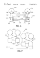
- FIG. 7 is a block diagram of a distributed fault resilient system.
- FIG. 8 is a block diagram of a fault tolerant system.
- FIG. 9 is flowchart of a fault diagnosis procedure used by IOPs of the system of FIG. 8 .
- FIG. 10 is a block diagram of a disaster tolerant system.
- FIG. 11 is a block diagram of software components of a computer system.
- FIGS. 12A and 12B are flow diagrams illustrating information transferred between CEs and IOPs.
- FIG. 13 is a flowchart of a flush procedure implemented by the CE Transport.
- FIGS. 14A and 14B are block diagrams illustrating physical and logical system configurations.
- FIG. 15 is a flowchart of a flush procedure.
- FIGS. 16A and 16B are tables of microcode state transitions.
- FIG. 17 is a block diagram of a system.
- FIG. 18 is a flow chart of a procedure for error processing.
- FIG. 19A is a syndrome source table.
- FIG. 19B is a state transition table corresponding to the syndrome source table of FIG. 19 A.
- FIG. 20 is a callout hierarchy diagram.
- FIGS. 21A, 21 B and 22 are tables listing callout elements.
- FIG. 23 is a flowchart of a procedure for identifying a faulty component.
- FIG. 1 illustrates a fault resilient system 10 that includes an I/O processor (“IOP”) 12 and two computing elements (“CEs”) 14 a , 14 b (collectively referred to as CEs 14 ).
- IOP I/O processor
- CEs 14 computing elements
- System 10 includes only a single IOP 12 and therefore cannot recover from a failure in IOP 12 . As such, system 10 is not entirely fault resilient.
- IOP 12 includes two inter-processor interconnect (“IPI”) modules 16 a , 16 b that are connected, respectively, to corresponding IPI modules 18 a , 18 b of CEs 14 by cables 20 a , 20 b .
- IOP 12 also includes a processor 22 , a memory system 24 , two hard disk drives 26 , 28 , and a power supply 30 .
- each CE 14 includes a processor 32 , a memory system 34 , and a power supply 36 . Separate power supplies 36 are used to ensure fault resilience in the event of a power supply failure.
- Processors 32 a , 32 b are “identical” to each other in that, for every instruction, the number of cycles required for processor 32 a to perform an instruction is identical to the number of cycles required for processor 32 b to perform the same instruction.
- system 10 has been implemented using standard Intel 486 based motherboards for processors 22 , 32 and four megabytes of memory for each of memory systems 24 , 34 .
- IOP 12 and CEs 14 of system 10 run unmodified operating system and applications software, with hard drive 26 being used as the boot disk for the IOP and hard drive 28 being used as the boot disk for CEs 14 .
- hard drive 26 being used as the boot disk for the IOP
- hard drive 28 being used as the boot disk for CEs 14 .
- each hard drive would also be duplicated.
- the operating system for IOP 12 and CEs 14 is DOS. However, other operating systems can also be used. Moreover, IOP 12 can run a different operating system from the one run by CEs 14 . For example, IOP 12 could run Unix while CEs 14 run DOS. This approach is advantageous because it allows CEs 14 to access peripherals from operating systems that do not support the peripherals. For example, if CEs 14 were running an operating system that did not support CD-ROM drives, and IOP 12 were running one that did, CEs 14 could access the CD-ROM drive by issuing I/O requests identical to those used to, for example, access a hard drive. IOP 12 would then handle the translation of the I/O request to one suitable for accessing the CD-ROM drive.
- FIG. 2 provides an overview of specialized system software 40 used by system 10 to control the booting and synchronization of CEs 14 , to disable local time in CEs 14 , to redirect all I/O requests from CEs 14 to IOP 12 for execution, and to return the results of the I/O requests, if any, from IOP 12 to CEs 14 .
- System software 40 includes two sets of IPI BIOS 42 that are ROM-based and are each located in the IPI module 18 of a CE 14 .
- IPI BIOS 42 are used in bootup and synchronization activities.
- IPI BIOS 42 replaces the I/O interrupt addresses in the system BIOS interrupt table with addresses that are controlled by CE Drivers 44 .
- the interrupt addresses that are replaced include those corresponding to video services, fixed disk services, serial communications services, keyboard services, and time of day services.
- CE Drivers 44 are stored on CE boot disk 28 and are run by CEs 14 .
- CE Drivers 44 intercept I/O requests to the system BIOS and redirect them through IPI modules 18 to IOP 12 for execution.
- CE Drivers 44 also respond to interrupt requests from IPI modules 18 , disable the system clock, and, based on information supplied by IOP Monitor 48 , control the time of day of CEs 14 .
- An IOP Driver 46 that is located on IOP boot disk 26 and is run by IOP 12 handles I/O requests from CEs 14 by redirecting them to an IOP Monitor 48 for processing. Thereafter, IOP Driver 46 transmits the results of the requests from IOP Monitor 48 to CEs 14 . IOP Driver 46 communicates with CE drivers 44 using a packet protocol.
- IOP Monitor 48 is located on IOP boot disk 26 and is run by IOP 12 . IOP Monitor 48 controls system 10 and performs the actual I/O requests to produce the results that are transmitted by IOP Driver 46 to CEs 14 .
- System software 40 also includes console software 49 that runs on IOP 12 and permits user control of system 10 .
- console software 49 a user can reset, boot, or synchronize a CE 14 .
- the user can also set one or both of CEs 14 to automatically boot (autoboot) and/or automatically synchronize (autosync) after being reset or upon startup.
- autoboot autoboot
- autosync automatically synchronize
- console software 49 the user can also place system 10 into either an integrity mode in which IOP Monitor 48 shuts down both CEs 14 when faced with a miscompare error, a first availability mode in which IOP Monitor 48 disables CE 14 a when faced with a miscompare error, or a second availability mode in which IOP Monitor 48 disables CE 14 b when faced with a miscompare error.
- console software 49 allows the user to request the status of system 10 .
- console software 49 is implemented using a separate processor that communicates with IOP 12 .
- Each CE 14 runs a copy of the same application and the same operating system as that run by the other CE 14 . Moreover, the contents of memory systems 34 a and 34 b are the same, and the operating context of CEs 14 are the same at each synchronization time. Thus, IOP Monitor 48 should receive identical sequences of I/O requests from CEs 14 .
- IOP Monitor 48 processes and monitors I/O requests according to a procedure 100 .
- IOP Monitor 48 waits for an I/O request from one of CEs 14 (step 102 ).
- IOP Monitor 48 waits for either an I/O request from CE 14 a or for the expiration of a timeout period (step 104 ). Because system 10 uses the DOS operating system, which halts execution of an application while an I/O request is being processed, IOP Monitor 48 is guaranteed not to receive an I/O request from CE 14 b while waiting (step 104 ) for the I/O request from the CE 14 a.
- IOP Monitor 48 checks to determine whether the timeout period has expired (step 106 ). If not (that is, if an I/O request packet from CE 14 a has arrived), IOP Monitor 48 compares the checksums of the packets (step 108 ). If the checksums are equal, IOP Monitor 48 processes the I/O request (step 110 ). After processing the I/O request, IOP Monitor 48 issues a request to the system BIOS of IOP 12 for the current time of day (step 112 ).
- IOP Monitor 48 After receiving the time of day, IOP Monitor 48 assembles an IPI packet that includes the time of day and the results, if any, of the I/O request (step 114 ) and sends the IPI packet to IOP Driver 46 (step 116 ) for transmission to CEs 14 .
- CEs 14 When CEs 14 receive the IPI packet, they use the transmitted time of day to update their local clocks which, as already noted, are otherwise disabled.
- execution in CEs 14 is suspended until IOP Monitor 48 returns the results of the I/O request through IOP Driver 46 .
- the times of day of both CEs 14 are updated to a common value corresponding to the transmitted time of day from the IPI packet. Accordingly, the CEs 14 are kept in time synchronization.
- the transmitted time of day is designated as the meta time. If a multitasking operating system were employed, execution in CEs 14 would not be suspended while IOP Monitor 48 performed the I/O request. Instead, processing in CEs 14 would be suspended only until receipt of an acknowledgement indicating that IOP Monitor 48 had begun processing the I/O request (step 110 ). The acknowledgement would include the time of day and would be used by CEs 14 to update the local clocks.
- IOP Monitor 48 After sending the IPI packet to IOP Driver 46 , IOP Monitor 48 verifies that both CEs 14 are online (step 118 ), and, if so, waits for an I/O request from one of the CEs 14 (step 102 ).
- IOP Monitor 48 disables the CE 14 that failed to respond (step 119 ) and processes the I/O request (step 110 ).
- IOP Monitor 48 checks to see if system 10 is operating in an availability mode or an integrity mode (step 120 ). If system 10 is operating in an availability mode, IOP Monitor 48 disables the appropriate CE 14 based on the selected availability mode (step 122 ), and processes the I/O request (steps 110 - 116 ). Thereafter, IOP Monitor 48 determines whether the disabled CE 14 has been repaired and reactivated (step 118 ). If not, IOP Monitor 48 waits for an I/O request from the online CE 14 (step 124 ). With one of the CEs 14 disabled, system 10 is no longer fault resilient and IOP Monitor 48 immediately processes a received I/O request (step 110 ).
- IOP Monitor 48 disables both CEs 14 (step 126 ) and stops processing (step 128 ).
- CE 14 a when the application or the operating system of, for example, CE 14 a makes a non-I/O call to the system BIOS, the system BIOS executes the request and returns the results to the application without invoking system software 40 .
- the application or the operating system makes an I/O BIOS call, CE Driver 44 a intercepts the I/O request. After intercepting the I/O request, CE Driver 44 a packages the I/O request into an IPI packet and transmits the IPI packet to IOP 12 .
- IPI module 16 a of IOP 12 When IPI module 16 a of IOP 12 detects transmission of an IPI packet from CE 14 a , IPI module 16 a generates an interrupt to IOP Driver 46 . IOP Driver 46 then reads the IPI packet.
- IOP Monitor 48 responds to the IPI packet from CE 14 a according to procedure 100 .
- IOP Driver 46 eventually transmits an IPI packet that contains the results of the I/O request and the time of day to CEs 14 .
- IPI modules 18 of CEs 14 receive the IPI packet from IOP 12 .
- CE Drivers 44 unpack the IPI packet, update the time of day of CEs 14 , and return control of CEs 14 to the application or the operating system running on CEs 14 .
- IPI Monitor 48 treats the quantum interrupt IPI packet as an IPI packet without an I/O request.
- IOP Monitor 48 detects the incoming quantum interrupt IPI packet (step 102 of FIG. 3) and, if a matching quantum interrupt IPI packet is received from the other CE 14 (steps 104 , 106 , and 108 of FIG. 3 ), issues a request to the system BIOS of IOP 12 for the current time of day (step 112 of FIG. 3 ).
- IOP Monitor 48 then packages the current time of day into a quantum response IPI packet (step 114 of FIG. 3) that IOP Driver 46 then sends to CEs 14 (step 116 of FIG. 3 ).
- CE Drivers 44 respond to the quantum response IPI packet by updating the time of day and returning control of CEs 14 to the application or the operating system running on CEs 14 .
- IOP Monitor 48 If IOP Monitor 48 does not receive a quantum interrupt IPI package from the other CE 14 within a predefined timeout period (step 106 of FIG. 3 ), IOP Monitor 48 responds by disabling the non-responding CE 14 .
- IPI modules 16 , 18 and cables 20 provide all of the hardware necessary to produce a fault resilient system from the standard Intel 486 based motherboards used to implement processors 22 , 32 .
- An IPI module 16 and an IPI module 18 which are implemented using identical boards, each perform similar functions.
- an IPI module 18 includes a control logic 50 that communicates I/O requests and responses between the system bus of a processor 32 of a CE 14 and a parallel interface 52 of IPI module 18 .
- Parallel interface 52 communicates with the parallel interface of an IPI module 16 through a cable 20 .
- Parallel interface 52 includes a sixteen bit data output port 54 , a sixteen bit data input port 56 , and a control port 58 .
- Cable 20 is configured so that data output port 54 is connected to the data input port of the IPI module 16 , data input port 56 is connected to the data output port of the IPI module 16 , and control port 58 is connected to the control port of the IPI module 16 .
- Control port 58 implements a handshaking protocol between IPI module 18 and the IPI module 16 .
- Control logic 50 is also connected to an IPI BIOS ROM 60 . At startup, control logic 50 transfers IPI BIOS 42 (FIG. 2 ), the contents of IPI BIOS ROM 60 , to processor 32 through the system bus of processor 32 .
- a QI counter 62 also located on IPI module 18 , generates quantum interrupts as discussed above.
- QI counter 62 includes a clock input 64 that is connected to the system clock of processor 32 and a gate input 66 that is connected to control logic 50 .
- Gate input 66 is used to activate and reset the counter value of QI counter 62 .
- QI counter 62 decrements the counter value by one during each cycle of the system clock of processor 32 .
- QI counter 62 When the counter value reaches zero, QI counter 62 generates a quantum interrupt that, as discussed above, activates CE Driver 44 (FIG. 2 ).
- CE Driver 44 deactivates QI counter 62 at the beginning of each I/O transaction.
- CE Driver 44 deactivates QI counter 62 by requesting an I/O write at a first address, known as the QI deactivation address.
- Control logic 50 detects the I/O write request and deactivates QI counter 62 through gate input 66 . Because this particular I/O write is for control purposes only, control logic 50 does not pass the I/O write to parallel interface 52 .
- CE Driver 44 resets and activates QI counter 62 by requesting an I/O write to a second address, known as the QI activation address.
- Control logic 50 responds by resetting and activating QI counter 62 .
- quantum interrupts are generated through use of debugging or other features available in processor 32 .
- Some commonly available processors include debugging or trap instructions that trap errors by transferring control of the processor to a designated program after the completion of a selected number of instructions following the trap instruction.
- CE Driver 44 issues a trap instruction to indicate that control of processor 32 should be given to CE Driver 44 upon completion of, for example, 300 instructions.
- the trap instruction causes control of processor 32 to be returned to CE Driver 44 .
- CE Driver 44 issues an instruction that cancels the trap instruction.
- IPI Module 18 is also used in activating an offline CE 14 .
- an offline CE 14 the contents of the memory system 34 of the active CE 14 are copied into the memory system 34 of the offline CE 14 .
- the processor 32 of the active CE 14 is permitted to continue processing and the memory is copied only during cycles in which the system bus of the processor 32 of the active CE 14 is not in use.
- IPI module 18 accounts for memory writes by the processor 32 to addresses that have already been copied to the offline CE 14 .
- control logic 50 monitors the system bus and, when the processor 32 writes to a memory address that has already been copied, stores the address in a FIFO 68 .
- FIFO 68 is modified to store both memory addresses and the contents of memory locations associated with the addresses, or to store the block addresses of memory blocks to which memory addresses being written belong.
- IPI module 18 also handles non-BIOS I/O requests.
- the BIOS is too slow to effectively perform I/O operations such as video display.
- some less structured or less disciplined operating systems such as DOS or UNIX, allow applications to circumvent the BIOS and make non-BIOS I/O requests by directly reading from or writing to the addresses associated with I/O devices.
- These non-BIOS I/O requests which cannot be intercepted by changing the system interrupt table, as is done in connection with, for example, I/O disk reads and writes, are problematic for a system in which synchronization requires tight control of the I/O interface.
- IPI module 18 includes virtual I/O devices that mimic the hardware interfaces of physical I/O devices. These virtual I/O devices include a virtual display 70 and a virtual keyboard 72 . As needed, other virtual I/O devices such as a virtual mouse or virtual serial and parallel ports could also be used.
- control logic 50 monitors the system bus for read or write operations directed to addresses associated with non-BIOS I/O requests to system I/O devices. When control logic 50 detects such an operation, control logic 50 stores the information necessary to reconstruct the operation in the appropriate virtual device. Thus, for example, when control logic 50 detects a write operation directed to an address associated with the display, control logic 50 stores the information necessary to reconstruct the operation in virtual display 70 .
- CE Driver 44 scans the virtual I/O devices and, if the virtual devices are not empty, assembles the information stored in the virtual devices into an IPI packet and transmits the IPI packet to IOP 12 .
- IOP 12 treats the packet like a BIOS I/O request using procedure 100 discussed above.
- control logic 50 detects a read addressed to a virtual I/O device, control logic 50 assembles the read request into an IPI packet for handling by IOP 12 .
- IOP 12 treats the IPI packet like a standard BIOS I/O request.
- each CE 14 always operates in one of eight states. Because there are only a limited number of permissible state combinations, system 10 always operates in one of fourteen states.
- the major CE operating states are OFFLINE, RTB (ready to boot), BOOTING, ACTIVE, RTS (ready to sync), WAITING, M_SYNC, (synchronizing as master), and S_SYNC (synchronizing as slave).
- IOP Monitor 48 changes the operating states of CEs 14 based on the state of system 10 and user commands from console software 49 . Through console software 49 , a user can reset a CE 14 at any time. Whenever the user resets a CE 14 , or a fault occurs in the CE 14 , IOP Monitor 48 changes the state of the CE 14 to OFFLINE.
- system 10 is operating with both CEs 14 OFFLINE (state 150 ).
- System 10 operates in the upper states of FIG. 5 (states 152 - 162 ) when CE 14 a becomes operational before CE 14 b and in the lower states (states 166 - 176 ) when CE 14 b is the first to become operational. If CEs 14 become operational simultaneously, the first operational CE 14 to be recognized by IOP Monitor 48 is treated as the first to become operational.
- the state of the CE 14 changes to RTB if the CE 14 is not set to autoboot or to BOOTING if the CE 14 is set to autoboot. For example, if CE 14 a issues a boot request when both CEs 14 are OFFLINE, and CE 14 a is not set to autoboot, then the state of CE 14 a changes to RTB (state 152 ). Thereafter, IOP Monitor 48 waits for the user, through console software 49 , to boot CE 14 a . When the user boots CE 14 a , the state of CE 14 a changes to BOOTING (state 154 ). If the user resets CE 14 a , the state of CE 14 a changes to OFFLINE (state 150 ).
- CE 14 a If both CEs 14 are OFFLINE when CE 14 a issues a boot request, and CE 14 a is set to autoboot, the state of CE 14 a changes to BOOTING (state 154 ). If CE 14 a boots successfully, the state of CE 14 a changes to ACTIVE (state 156 ).
- CE 14 a When CE 14 a is ACTIVE, and CE 14 b issues a boot request, or if CE 14 b had issued a boot request while the state of CE 14 a was transitioning from OFFLINE to ACTIVE (states 152 - 156 ), the state of CE 14 b changes to RTS (state 158 ) if CE 14 b is set to autosync and otherwise to WAITING (state 160 ). If the state of CE 14 b changes to RTS (state 158 ), IOP Monitor waits for the user to issue a synchronize command to CE 14 b . When the user issues such a command, the state of CE 14 b changes to WAITING (state 160 ).
- IOP Monitor 48 copies the contents of memory system 34 a of CE 14 a into memory system 34 b of CE 14 b . Once the memory transfer is complete, IOP Monitor 48 waits for CE 14 a to transmit a quantum interrupt or I/O request IPI packet. Upon receipt of such a packet, IOP Monitor 48 changes the state of CE 14 a to M_SYNC and the state of CE 14 b to S_SYNC (state 162 ), and synchronizes the CEs 14 . This synchronization includes responding to any memory changes that occurred while IOP Monitor 48 was waiting for CE 14 a to transmit a quantum interrupt or I/O request IPI packet. Upon completion of the synchronization, the states of the CEs 14 both change to ACTIVE (state 164 ) and system 10 is deemed to be fully operational.
- IOP Monitor 48 does not wait for memory transfer to complete before changing the state of CE 14 a to M_SYNC and the state of CE 14 b to S_SYNC (state 162 ). Instead, IOP Monitor 48 makes this state change upon receipt of an IPI packet from CE 14 a and performs the memory transfer as part of the synchronization process.
- CE 14 b Similar state transitions occur when CE 14 b is the first CE 14 to issue a boot request. Thus, assuming that CE 14 b is not set to autoboot, CE 14 b transitions from OFFLINE (state 150 ) to RTC (state 166 ) to BOOTING (state 168 ) to ACTIVE (state 170 ). Similarly, once CE 14 b is ACTIVE, and assuming that CE 14 a is not set to autosync, CE 14 a transitions from OFFLINE (state 170 ) to RTS (state 172 ) to WAITING (state 174 ) to S_SYNC (state 176 ) to ACTIVE (state 164 ).
- a fault resilient system 200 includes two IOPs 202 and two CEs 204.
- Each CE 204 is connected, through an IPI card 206 and a cable 208 , to an IPI card 210 of each IOP 202.
- IOPs 202 are redundantly connected to each other through IPI cards 210 and cables 212 . Because every component of-system 200 has a redundant backup component, system 200 is entirely fault resilient.
- cables 208 and 210 could be replaced by a pair of local area networks to which each IOP 202 and CE 204 would be connected. Indeed, local area networks can always be substituted for cable connections.
- System 200 is operating system and application software independent in that it does not require modifications of the operating system or the application software to operate. Any single piece of hardware can be upgraded or repaired in system 200 with no service interruption. Therefore, by sequentially replacing each piece of hardware and allowing system 200 to resynchronize after each replacement, the hardware of system 200 can be replaced in its entirety without service interruption. Similarly, software on system 200 can be upgraded with minimal service interruption (that is, during the software upgrade, the application will become unavailable for an acceptable period of time such as two seconds). Also, disaster tolerance for purposes of availability can be obtained by placing each IOP/CE pair in a separate location and connecting the pairs through a communications link.
- a distributed, high performance, fault resilient system 220 includes two systems 200 , the IOPs 202 of which are connected to each other, through IPI modules, by cables 222 .
- System 220 uses distributed computing environment software to achieve high performance by running separate portions of an application on each system 200 .
- System 220 is fault tolerant and offers the ability to perform both hardware and software upgrades without service interruption.
- a fault tolerant system 230 includes three IOPs (232, 234, and 236) and three CEs (238, 240, and 242).
- IPI modules 244 and cables 246 each IOP is connected to an IPI module 244 of each of the other IOPs.
- IPI modules 248 and cables 250 each CE is connected to an IPI module 244 of two of the IOPs, with CE 238 being connected to IOPs 232 and 234, CE 240 being connected to IOPs 232 and 236, and CE 242 being connected to IOPs 234 and 236.
- system 230 allows for hardware upgrades without service interruption and software upgrades with only minimal service interruption.
- system 230 is more capable of identifying the source of a hardware fault than is system 10 .
- system 10 simply disables one or both of CEs 14 when an error is detected, system 230 offers a higher degree of fault diagnosis.
- each IOP (232, 234, 236) of system 230 performs fault diagnosis according to a procedure 300 .
- each IOP (232, 234, 236) checks for major faults such as power loss, broken cables, and nonfunctional CEs or IOPs using well known techniques such as power sensing, cable sensing, and protocol timeouts (step 302 ).
- major faults such as power loss, broken cables, and nonfunctional CEs or IOPs using well known techniques such as power sensing, cable sensing, and protocol timeouts.
- each IOP disables the faulty device or, if necessary, the entire system.
- each IOP waits to receive IPI packets (that is, quantum interrupts or I/O requests) from the two CEs to which the IOP is connected (step 304 ).
- IPI packets that is, quantum interrupts or I/O requests
- IOP 232 waits to receive IPI packets from CEs 238 and 240.
- each IOP transmits the checksums (“CRCs”) of those IPI packets to the other two IOPs and waits for receipt of CRCs from the other two IOPs (step 306 ).
- CRCs checksums
- each IOP may generated a three by three matrix in which each column corresponds to a CE, each row corresponds to an IOP, and each entry is the CRC received from the column's CE by the row's IOP (step 308 ).
- IOP 232 generates the following matrix:
- CE 238 CE 240 CE 242 IOP 232 CRC CRC X IOP 234 CRC X CRC IOP 236 X CRC CRC
- IOP 232 After generating the matrix, IOP 232 sums the entries in each row and each column of the matrix. If the three row sums are equal and the three column sums are equal (step 310 ), then there is no fault and IOP 232 checks again for major faults (step 302 ).
- IOP 232 compares the CRC entries in each of the columns of the matrix. If the two CRC entries in each column match (step 312 ), then IOP 232 diagnoses that a CE failure has occurred and disables the CE corresponding to the column for which the sum does not equal the sums of the other columns (step 314 ).
- IOP 232 determines how many of the columns include mismatched entries. If the matrix includes only one column with mismatched entries (step 315 ), then IOP 232 diagnoses that the path between the IOP corresponding to the matrix row sum that is unequal to the other matrix row sums and the CE corresponding to the column having mismatched entries has failed and disables that path (step 316 ). For purposes of the diagnosis, the path includes the IPI module 244 in the IOP, the IPI module 248 in the CE, and the cable 250 .
- IOP 232 confirms that one matrix row sum is unequal to the other matrix row sums, diagnoses an IOP failure, and disables the IOP corresponding to the matrix row sum that is unequal to the other matrix row sums (step 318 ).
- IOP 232 determines that system 300 still includes sufficient non-faulty hardware to remain operational, IOP 232 checks again for major faults (step 302 ). Because system 230 is triply redundant, system 230 can continue to operate even after several components have failed. For example, to remain operating in an availability mode, system 230 only needs to have a single functional CE, a single functional IOP, and a functional path between the two.
- each IOP (232, 234, 236) can correctly diagnose any single failure in a fully operational system 230 or in a system 230 in which one element (that is, a CE, an IOP, or a path) has previously been disabled.
- each IOP accounts for CRCs that are not received because of the disabled element by using values that appear to be correct in comparison to actually received CRCs.
- Procedure 300 is not dependent on the particular arrangement of interconnections between the CEs and IOPs. To operate properly, procedure 300 only requires that the output of each CE be directly monitored by at least two IOPs. Thus, procedure 300 could be implemented in a system using any interconnect mechanism and does not require point to point connections between the CEs and IOPs. For example, the CEs and IOPs could be connected to at least two local area networks. In an alternative approach, instead of summing the CRC values in the rows and columns of the matrix, these values can be compared and those rows or columns in which the entries do not match can be marked with a match/mismatch indicator.
- each IOP 202 of system 200 generates a two by two matrix in which each column corresponds to a CE 204 and each row corresponds to a IOP 202:
- CE 204 CE 204 IOP 202 CRC CRC IOP 202 CRC CRC
- each IOP 202 After generating the matrix, each IOP 202 attaches a mismatch indicator to each row or column in which the two entries are mismatched.
- an IOP 202 has faulted. Depending on the operating mode of system 200 , an IOP 202 either disables another IOP 202 or shuts down system 200 .
- the IOP 202 to be disabled is selected based on user supplied parameters similar to the two availability modes used in system 10 .
- IOPs 202 respond by disabling a CE 204 if system 200 is operating in an availability mode or, if system 200 is operating in an integrity mode, shutting down system 200 . If both rows and one column have mismatch indicators, then one of the paths between the IOPs 202 and the CE 204 corresponding to the mismatched column has failed. Depending on the operating mode of system 200 , IOPs 202 either disable the CE 204 having the failed path or shut down system 200 . If both rows and both column have mismatch indicators, then multiple faults exist and IOPs 202 shut down system 200 .
- the IOP 202 corresponding to the mismatched row has faulted. Depending on the operating mode of system 200 , the other IOP 202 either disables the faulty IOP 202 or shuts down system 200 . If one row and one column have mismatch indicators, then the path between the IOP 202 corresponding to the mismatched row and the CE 204 corresponding to the mismatched column has failed. Depending on the operating mode of system 200 , IOPs 202 either account for the failed path in future processing or shut down system 200 .
- one embodiment of a disaster tolerant system 260 includes two fault tolerant systems 230 located in remote locations and connected by communications link 262 , such as Ethernet or fiber, and operating in meta time lockstep with each other. To obtain meta time lockstep, all IPI packets are transmitted between fault tolerant systems 230 . Like system 220 , system 260 allows for hardware and software upgrades without service interruption.
- the paired modular redundant architecture of the invention allows for varying levels of fault resilience and fault tolerance through use of CEs that operate asynchronously in real time and are controlled by IOPs to operate synchronously in meta time.
- This architecture is simple and cost-effective, and can be expanded or upgraded with minimal difficulty.
- FIG. 11 depicts the components of the system software architecture of an alternative embodiment of the invention that includes multiple CEs and multiple IOPs.
- Each CE 1100 includes a set of one or more Physical Device Redirectors 1105 , a CE Transport layer 1110 , and an IPI Driver 1115 .
- the Physical Device Redirectors 1105 intercept I/O requests directed to peripheral devices, package the requests, and send the requests to the CE Transport 1110 .
- the Physical Device Redirectors 1105 also receive responses to the requests from the CE Transport 1110 , unpackage the responses, and return the responses to the operating system or applications software that initially made the I/O requests to the peripheral devices.
- the system software architecture depicted in FIG. 11 supports a multi-threaded processing environment.
- each thread is a separate stream of instructions that may be processed by the computing element.
- a Physical Device Redirector 1105 intercepts an I/O request by a particular thread, processing of that thread stops until the Physical Device Redirector 1105 returns the response to the request.
- the CE Transport 1110 communicates I/O requests between the CEs and the IOPs.
- the CE Transport also keeps track of responses expected and received from the IOPs on a per request basis.
- the CE Transport searches for completed requests (i.e., requests to which all IOPs have responded) as IOP responses to redirected requests are received and sends the resultant data to the Physical Device Redirector 1105 .
- Each IOP 1150 includes an IPI driver 1155 , a state control program (SCP) 1160 , a fault handler 1165 , an IOP Transport layer 1170 , a Device Synchronization Layer (DSL) 1175 , and a set of one or more Physical Device Providers 1180 .
- the IPI Drivers 1115 , 1155 of both the CEs and the IOPs control the actual transmission and reception of data along the interconnect paths 1185 between the CEs and the IOPs.
- the state control program 1160 initiates and responds to state transitions involving the IOPs and the CEs.
- the fault handler 1165 responds to reports of detected faults by deconfiguring appropriate hardware components.
- the IOP Transport 1170 transports data between the IPI Driver and the other software components of the IOPs.
- the Device Synchronization Layer 1175 is responsible for synchronizing all redirected requests and responses between IOP-based peripherals. This synchronization includes the reprocessing and restructuring of the requests and responses due to state transitions of the IOPs, the CEs, or the peripheral devices.
- the Physical Device Providers 1180 unpackage requests received from the DSL 1175 , process the requests, package responses, and send the responses to the DSL 1175 .
- Each IOP also may include an ethernet driver 1190 or other mechanism that permits direct communication between the IOPs.
- the architecture of the described embodiments requires redirection of all I/O requests from the CEs to one or more IOPs. Responses to these redirected requests must be synchronized. Accordingly, all IOPs responding to a redirected request must respond to the request in a known way and must describe how all other IOPs will respond. Moreover, an IOP must respond to a redirected request even if the IOP does not have a device capable of processing the request. These requirements permit software running on the CEs to compare the responses of the IOPs for consistency.
- FIGS. 12A and 12B provide an illustrative example of appropriate IOP responses (FIG. 12B) to requests by a CE (FIG. 12 A).
- each disk of a two-disk shadow set is associated with a different IOP, with the disk 1200 associated with the first IOP 1205 functioning normally and the disk 1210 associated with the second IOP 1215 being offline.
- a request from the CE 1100 to the shadow set for data is redirected to the IOPs, and both IOPs respond.
- the second IOP 1215 receives all requests directed to the shadow set even though its associated disk 1210 is offline.
- Each IOP indicates that the first IOP 1205 is responding with the expected data and that the second IOP 1215 is responding with no data.
- the CE Transport 1110 monitors the responses provided by the IOPs.
- the CE Transport compares the responses for consistency once all IOPs have responded to a request. The responses must be consistent in indicating which IOPs responded to the request with actual data and which IOPs did not. Moreover, if more than one IOP responds with data, then the data provided by the IOPs must be consistent. If the responses pass the consistency checks, then the CE Transport provides a response containing actual data to the appropriate Physical Device Redirector 1105 in the CE 1100 and discards the no-data response. Thereafter, the CE Transport informs the IOPs that all IOPs have responded to the request and further informs the IOPs of the outcome of the comparison. If the responses do not pass the consistency checks, then one of the IOPs is disabled and, in effect, removed from the architecture.
- the CE Transport 1110 implements the request-response architecture employed by the system of FIG. 11 using the procedure 1300 illustrated in FIG. 13 .
- the CE Transport first instructs the IPI Driver 1115 to send a request from a Physical Device Redirector 1105 to all IOPs 1150 (step 1305 ).
- the CE Transport 1110 initializes a timer. If the timer has not expired (step 1310 ) before all responses are received (step 1315 ), then the CE Transport compares the responses to determine whether they are consistent (step 1320 ). If the responses are consistent and there are multiple responses that include data (step 1325 ), then the CE transport compares the data responses (step 1330 ).
- the CE Transport sends the data to the appropriate Physical Device Redirector 1105 (step 1335 ). Finally, the CE Transport instructs the IPI driver to send a Response Complete message to all of the IOPs (step 1340 ).
- step 1310 If the timer expires (step 1310 ) before all responses are received, or if inconsistent responses are received (steps 1320 , 1330 ), then the CE Transport reports the occurrence of an error (step 1345 ) and instructs the IPI driver to send a Response Complete message to all of the IOPs (step 1340 ).
- the Device Synchronization Layer (DSL) 1175 makes all IOP-based physical devices appear to the CEs as logical or virtual devices.
- the DSL combines device and state information from all IOPs and uses this information to project a single logical IOP to the Physical Device Redirectors of the CEs.
- a system configured as illustrated in FIG. 14A would appear to the CE-based Physical Device Redirectors as having the logical representation illustrated in FIG. 14 B.
- the DSL 1175 represents devices logically so that the CE-based redirectors have no knowledge of the locations and characteristics of physical devices. For example, a SCSI redirector would not know that Disk C: ( 1400 , 1405 ) and Disk D: ( 1410 , 1415 ) are shadowed drives and would simply treat them as though they were each a single drive ( 1420 , 1425 ). Also, an Ethernet redirector would not know that multiple Ethernet controllers provide a primary controller ( 1430 ) and a secondary controller ( 1435 ) and instead would be aware only of a single Ethernet controller ( 1440 ).
- the DSL 1175 receives all redirected requests from the IOP Transport 1170 .
- the DSL decides whether to send a request to a Physical Device Provider 1180 or to send a no-data response.
- a critical function of the DSL is that it only sends a request to a device provider when that provider is expected to process the request. For example, if two IOPs control a shadow set of disks, with the first IOP controlling an offline disk and the second IOP controlling an active disk, the DSL of the first IOP would not send a request to its disk, and would instead respond with a no-data response. The DSL on the second IOP would send the request to its disk, and would eventually respond with the data from its disk along with an indication that the first IOP would be providing a no-data response.
- the DSL 1175 indicates how every other IOP will respond.
- the DSL accomplishes this by maintaining a record of the status of every other IOP and associated device in an internal device state table.
- the DSL 1175 also accounts for the effects of state changes in the CEs, the IOPs or the peripheral devices. For example, the DSL accounts for the situation that arises when the state of a peripheral device changes after an IOP indicates how the other IOPs will respond to a request, but before the other IOPs actually respond to the request. If the other IOPs were to respond after the state change, their responses could differ from the response expected by the first IOP.
- the DSL solves this problem by disabling all response transmissions from the affected device and initiating a flush sequence that causes the CE Transport to discard all previously received, incomplete responses for the particular device. (As previously noted, the CE Transport does not consider a request to be complete until responses to the request have been received from all IOPs.)
- the DSL 1175 of each IOP 1150 Upon receipt of a flush completion indication from the CE Transport 1110 , the DSL 1175 of each IOP 1150 updates its internal device state table and reenables transmission of responses for the particular device. Finally, the DSL reprocesses any incomplete responses that were submitted to the CE Transport prior to the flush.
- the CE Transport 1110 sends an indication to the DSL 1175 of each IOP upon completion of each response. As such, the DSL always knows which responses are complete. This permits the DSL to keep track of incomplete responses. When a device state change occurs and an ensuing flush is issued, the DSL can, upon receipt of the flush complete indication, reset its internal knowledge of the device state and re-issue any affected incomplete requests.
- This functionality is critical, for example, to the implementation of standby-primary processing since the DSL may have responded to a particular request on behalf of a standby device with a no-data response. If the primary device failed and was unable to process the request, the DSL would initiate the flush sequence and re-issue the request. This time the standby device would be considered the primary device (since the primary device had failed) and would receive the request.
- the internal state table of the DSL 1175 keeps track of all flushes that can affect the I/O devices and the IOPs.
- the DSL through use of the state table, permits multiple flushes to affect one or more devices, and permits multiple state transitions to occur at a single time. This permits seamless handling of multiple related or unrelated component state changes.
- the DSL 1175 also mandates that all device state changes originate from the IOP 1150 that owns the device. This permits the DSLs of different IOPs to have a different simultaneous idea of the state of a device without risk that inconsistency problems will occur at the CE Transport 1110 . This also permits the DSL to be fully distributed since there is no need to freeze request or response queues while a master software entity determines whether a steady state operation has been achieved.
- the Physical Device Providers 1180 need not consider the state of a peripheral device or an IOP because the DSL 1175 only sends a request to a device provider when the device provider is expected to process the request.
- the DSL does not consider the I/O policy associated with a particular device. For example, the DSL does not consider whether a disk device has a shadowed or a single-ended I/O policy.
- the DSL does use I/O policies to determine which providers on which IOPs will receive a particular request to process. This permits the DSL to arbitrarily treat any device as shadowed, singled-ended, virtual, or primary/standby even though all combinations of I/O policies and device types do not necessarily make sense.
- the DSL 1175 handles all device state transitions, including device failure, device activation, device merge, and manual device enable/disables
- the DSL transparently handles all IOP state transitions, including IOP joining, IOP activation, IOP removal, and IOP graceful shutdown, as these transitions relate to device states.
- the DSL also responds automatically to requests that cannot be satisfied on behalf of the device providers.
- the DSL provides a full featured application program interface (API) set that is useable by developers.
- API application program interface
- the DSL 1175 provides automatic request timeout support.
- the DSL starts a recovery process if a CE-originated request does not complete within a specified period of time.
- the DSL determines which IOP 1150 has stalled and notifies the fault handler.
- the DSL 1175 can apply any I/O policy to any physical device.
- the DSL can configure a hard disk as a single-ended device instead of a shadowed device.
- the DSL can configure, for example, a CD-ROM player or a serial port as a standby/active device instead of as a single-ended device.
- the DSL 1175 initiates a flush sequence in the CE Transport 1110 of one or more CEs 1100 in response to a state change in a peripheral device or an IOP 1150 .
- the flush sequence causes the CE Transport to flush all outstanding activity in the messaging pipeline of the corresponding CE with respect to indicated devices or Physical Device Providers 1180 and to provide notification of completed requests as a result of the flushing.
- the flush mechanism provides varying granularity of request-response synchronization as required by the DSL.
- a system-wide flush can be implemented for all devices (or Physical Device Providers), or a flush can be implemented for a class of devices or a specific device.
- the DSL of each IOP Upon completion of the flush sequence, the DSL of each IOP knows exactly which request-response pairs have been processed and completed. The DSL uses this knowledge to reissue, re-execute or re-transmit any necessary request-response pairs to permit recovery from the transition (or stimulus) within the system that disrupted the steady state operation of one or more devices. This allows the DSL to react to changes in the system that affect steady state operation of the devices. Once a flush sequence is initiated and completed, the DSL can determine exactly which requests or responses must be reprocessed or redirected to other devices for completion.
- Each CE Transport 1110 maintains a database of outstanding requests.
- the database includes a list of all outstanding I/O requests in the system, each identified by a unique identifier called a XRN (Transport Reference Number).
- the flush sequence is carried out according to the procedure 1500 illustrated in FIG. 15 .
- the DSL 1175 of each IOP 1150 initiates a flush sequence by sending a flush request to all of the CEs 1100 (step 1505 ).
- the DSL then suspends all request/response processing activity for the devices that are involved in the flush sequence until the flush sequence is completed (step 1510 ).
- Each CE receives a flush request and waits for matching flush requests from every IOP in the system (step 1515 ).
- the CE enters the flush request into the database and tracks the flush request in the same way that the CE tracks operating system requests.
- the CE indicates that the first portion of the flush sequence is completed.
- the completion of this portion of the flush sequence signifies that all activity that was in the IOP-to-CE message pipelines has been flushed out and processed by the CEs.
- the CE Before acknowledging completion of the flush sequence, the CE first sends acknowledgments to the IOPs as to which outstanding requests have been completed (step 1520 ). In some cases, I/O requests may be completed by flushing responses through the IOP-to-CE pipelines. The CE sends a SWTACK (Software Transaction Acknowledgment) for each request that was completed and removes the completed request from the database. Each SWTACK contains the request's original XRN. The XRN allows the IOPs to associate the SWTACK with the proper completed request.
- SWTACK Software Transaction Acknowledgment
- the CE After sending a SWTACK for each completed request, the CE sends a SWTACK for the flush sequence (step 1530 ). Messages are delivered in order through the CE-to-IOP message pipelines (or are reordered to reflect their transmission sequence). Accordingly, the flush SWTACK serves to flush the request completion notification SWTACKs through the CE-to-IOP message pipelines.
- the DSL receives the SWTACK for the flush sequence (step 1535 )
- the DSL has already received and processed all SWTACKs for requests that were originally in the message pipelines and have since completed (step 1525 ).
- the DSL Upon receiving the SWTACK for the flush sequence, the DSL knows the state of all request/response activity in the system.
- the DSL responds to this information by updating the state of the system (step 1540 ). Thereafter, the DSL resumes request-response activity for affected devices (step 1545 ), and resends any incomplete affected requests (step 1550 ). This re-synchronizes the devices against the new state to achieve a steady state of operation for the device or devices involved in the flush sequence.
- each flush sequence is uniquely tagged with its own XRN, more than one flush can be in progress at a time.
- the flush processing software in the CE Transport and the DSL abides by certain rules as to how outstanding flush sequences are processed and in what order they are acknowledged. This allows the DSL to preempt or override previously-issued flush sequences due to subsequent or secondary transitions that might occur within the system.
- the system software implements a freeze protocol to ensure that IOP-to-CE communications will not affect meta time synchronization of the CEs.
- the IOPs operate asynchronously to the CEs and to other IOPs due to the asynchrony inherent in I/O devices. For this reason, communication between the CEs and the IOPs needs to occur in a way that will not disturb the meta time synchronization of the CEs.
- CE-to-IOP communication is synchronous to the CE instruction stream and will not affect CE lockstep as long as sufficient buffering is provided.
- IOP-to-CE communication is by nature asynchronous to the instruction stream of each CE.
- the freeze protocol serves to delay processing of asynchronous data from the IOPs until the data can be handled synchronously by all CEs.
- the freeze protocol serves to delay implementation of the procedure 1300 by the CE Transports 1110 until all of the CE Transports 1110 are ready to implement the procedure 1300 .
- the freeze protocol provides four primary features: synchronized processing of input data streams from the asynchronous IOPs across the loosely synchronized CEs; synchronized time updates to the CEs; a deep-freeze mechanism that allows an IOP to synchronously hold all CEs in a captive state for an extended period of time; and fault detection/diagnosis with respect to the communication paths between the CEs and the IOPs.
- the freeze protocol provides CE synchronization using a so-called freeze cycle.
- the CE Transport 1110 of a CE may initiate a freeze cycle each time that it is activated by a Physical Device Redirector 1105 to service a redirected I/O operation.
- implementations of the software may initiate a freeze cycle every time that a certain number of I/O requests occurs or a certain number of instructions are processed without an I/O request.
- the CE Transport 1110 may implement a freeze cycle with every fifth I/O request or every ten thousand instructions.
- the CE Transport 1110 initiates a freeze cycle by transmitting a high-priority freeze request message to all active IOPs and waiting for freeze response messages from all active IOPs. Since all of the CEs are processing the same instruction stream, the CE transport 1110 of each active CE will transmit a freeze request message to all active IOPS. Each IOP receives the freeze request messages from the CEs. When an IOP has received a freeze request message from all active CEs, this indicates that the CEs are at the same point in their instruction streams (i.e., in synchronization) and that it is permissible for the CEs to process received data using the procedure 1300 . Accordingly, the IOP responds by sending a freeze response message to ail active CEs.
- the CEs 1100 receive the freeze response messages from the IOPs and place the messages in the normal-priority message queues of the IPI Driver 1115 to provide an inter-CE synchronization point for the CE Transport 1110 . Finally, after receiving freeze response messages from all active IOPs, the CEs terminate the freeze cycle by transmitting freeze release messages to the IOPs.
- the CE Transport 1110 invokes the freeze cycle through the IPI Driver 1115 .
- the IPI Driver responds by initiating the freeze cycle (i.e., sending the freeze request message) and returning control to the CE Transport 1110 .
- the CE Transport performs whatever useful work it can, such as transmitting normal priority messages, or draining and processing messages from the receive queue of the CE 1100 .
- the CE Transport does not return control to the operating system until the CE Transport has encountered a freeze response message in the normal-priority receive queue corresponding to each active IOP.
- the IPI Driver 1115 attempts to complete the freeze cycle as quickly as possible.
- the IPI Driver composes a priority message and sends the message to all active IOPs 1150 .
- the message carries no data to the IOPs and merely serves as an indication that the freeze cycle has started.
- the IPI Driver starts a freeze response timeout counter after sending the priority message to detect failure of any IOP to respond.
- the length of this counter is on the order of twice the worst-case message transmit time. This provides each IOP with sufficient time to complete transmission of any normal priority message that it may be transmitting upon receipt of the freeze request message before the IOP transmits a freeze response message.
- normal priority messages have a size limit of, for example, 64 kilobytes, to ensure that the worst-case message transmit time will have a reasonable value.
- the IPI Driver 1155 of each IOP 1150 places a timestamp update in the freeze response message. This timestamp corresponds to the number of clock ticks since the last freeze response message transmitted by the IOP. Thus, a CE 1100 may receive different timestamp updates from different IOPs. Accordingly, the CEs designate one IOP 1150 as a meta-time server to ensure that all CEs will update their local time clock identically.
- the IPI Driver 1155 of the IOP 1150 After receiving a freeze request message from all active CEs, the IPI Driver 1155 of the IOP 1150 sends the freeze response message as a microcode-formatted priority message. Upon sending the message, the IOP initiates a freeze release timeout counter to detect failure of a CE to respond to the freeze response.
- the IPI Driver 1115 of each CE is interrupted to service the incoming freeze response message, and responds by reformatting the message into a normal-priority message and placing the message at the bottom of the normal-priority message queue. Placement of the message in the message queue completes the time-critical portion of the freeze cycle, since it permits the CE Transport 1110 to return control to the operating system.
- the IPI Driver 1115 broadcasts a freeze release message to the active IOPs. This completes the freeze cycle for the CE 1100 .
- the IOP 1150 receives the release message and cancels the freeze release timer upon receipt of a release message from every active CE 1100 .
- time updates are provided to the operating system by including time increments in the freeze response packet.
- the IOP IPI Drivers 1155 maintain the time increments using an internal 100 ⁇ s timer interrupt. Only one of the IOPs is designated as the time provider, and the time increment from that IOP is used by all of the CEs.
- the IOP's IPI Driver 1155 transmits the delta time since the last freeze response-packet was transmitted as the time increment.
- the CE Transport 1110 uses this value to update the time-of-day clock of the operating system after a freeze response packet has been processed for all receive queues.
- a deep freeze protocol is a variation of the normal freeze protocol and serves to suspend normal activity between the CEs and the IOPs to allow major system state transitions to occur.
- the deep freeze state is invoked by the IOP software, which uses the IOP Transport 1170 to command the IOP IPI Driver 1155 to replace the next freeze response message with a deep freeze response message.
- the format of the deep freeze response message is identical to that of the normal freeze response message with the exception that different opcodes are used to designate the two types of messages.
- the deep freeze response carries a meta-time update like a normal freeze response.
- the deep freeze response causes the initiating IOP to disable its transmitter without initiating a timeout counter.
- the IOP's IPI Driver 1155 sends the deep freeze response to all active CEs to inform them that a deep freeze state is requested.
- the CEs respond by converting the deep freeze response to a normal-priority response message and adding the message to the normal-priority message queue, with an indication that the message is a deep freeze response instead of a normal freeze response.
- the CEs a continue to process normal freeze response messages from the other IOPs in the normal manner.
- the CE's IPI Driver 1115 After receiving a normal freeze response or a deep freeze response from all active IOPs, the CE's IPI Driver 1115 sends a deep freeze request message to the IOPs that are not yet in the deep freeze state and restarts the freeze response timer.
- Receipt of a deep freeze request informs the IOPs that another IOP has injected a deep freeze cycle into the current freeze cycle. (Normally, the IOP IPIs would have received a freeze release message.) Each IOP responds to the freeze request by cancelling the freeze release timeout counter, turning off the IOP's transmitter path, sending to all active CEs a deep freeze response message with a meta-time update since the previous freeze response, and restarting the freeze release timeout counter.
- the IPI Drivers 1155 of the CEs receive the deep freeze responses and insert them into the appropriate receive queues. Upon receipt of a deep freeze response from each active IOP, the CE Transport 1110 cancels the response timer and issues the normal freeze release message to the IOPs.
- the CE Transport 1110 in the mean time, has encountered a combination of normal freeze response messages and deep freeze response messages in the various receive queues. Detection of a single deep freeze response causes the CE transport to process beyond the normal freeze response to the deep freeze response. Hence, the CE IPI Driver 1115 must ensure that both the freeze responses and the deep freeze responses make their way into the receive queues in the proper order.
- the deep freeze state is terminated by initiating a deep freeze termination cycle with the issuance of a deep freeze termination request.
- the deep freeze termination cycle typically is originated by the IOP Transport 1170 that invoked the deep freeze cycle, but any IOP Transport 1170 can invoke a deep freeze termination cycle with the same result.
- the deep freeze termination request is a register-level request to the IPI Driver 1155 that causes the driver to broadcast a deep freeze termination priority message to all active CEs.
- the IPI Driver 1115 of each CE receives this message and echoes the message to all active IOPs.
- the IOPs Upon receiving the deep freeze termination message, the IOPs activate their transmission paths and exit the deep freeze state.
- the freeze response timers and the freeze release timers account for the occurrence of errors during the freeze protocol. If a CE's freeze response timer expires, the CE generates a high priority system error (SYSERR) packet containing the CE's freeze status virtual register and sends it to all active IOPs. The IOPs supplement the SYSERR packet with relevant state information of their own and forward the SYSERR packet to the Fault Handlers 1165 .
- SYSERR system error
- the IOP If an IOP's freeze release timer expires, the IOP generates a local SYSERR packet containing only state information from the detecting IOP and passes this SYSERR packet to the Fault Handler 1165 .
- the detecting IOP then sends a similar SYSERR packet to all active CEs.
- the CEs supplement the SYSERR packet with their own state information and echo the SYSERR packet back to all active IOPs.
- the IOPs store additional state information in the echoed SYSERR and forward the message to the Fault Handler 1165 .
- the IPI Driver 1115 , 1155 of the CE 1100 or the IOP 1150 waits for the Fault Handler 1165 residing on the IOP 1150 to resolve the error condition.
- the Fault Handler determines which path is at fault and commands the IOP IPI Driver 1155 to disable the faulty path.
- the IOP IPI Driver evaluates the state of the freeze protocol and resumes normal processing once the requirements for such processing are met.
- the IOPs do not apply a timeout for the reception of freeze requests from all active CEs. If one or more CEs fail to send a freeze request message, or if a freeze request message is not received for some other reason, the other CEs will eventually generate a freeze response timeout SYSERR packet.
- the CE IPI Driver 1115 state transitions required to service the freeze protocol, including the deep freeze extension, are illustrated in FIG. 16 A.
- the IOP IPI Driver 1155 state transitions required to service the freeze protocol, including the deep freeze extension, are illustrated in FIG. 16 B.
- the system implements a message based fault notification and reporting environment using Fault Handler 1165 .
- the system can be viewed of as including error reporting elements and error processing elements.
- the error reporting elements are any components in the system that detect error conditions or determine status conditions and transmit the information to an error processing element.
- the error processing elements, or fault handlers receive error information from the reporting elements.
- a fault handler uses the error messages associated with a fault event to identify a particular system component that has failed and caused the fault event. The identified component is referred to as a callout. A fault handler may also take or initiate action to resolve the fault and restore normal, if degraded, system operation.
- Error reporting elements may be either hardware or software entities. The only requirement is that they must be capable of transmitting error information to the error processing elements or causing such information to be transmitted.
- An error reporting element that detects a system error encapsulates the system error into a uniformly formatted packet referred to as a SYSERR.
- the error reporting element then sends the SYSERR (or causes the SYSERR to be sent) to all error processing elements that have connectivity to the reporting element.
- the architecture of the physical system is configured so that any error condition causes generation of at least one SYSERR packet.
- the physical system is also configured so that, ideally, each error reporting element is connected to every error processing element. This permits the lack of an error indication when one was expected to be used as diagnostic information.
- a single SYSERR packet may not unambiguously identify the source of a fault event in many instances.
- the fault handlers rely on the diagnostic information provided by SYSERR packets from multiple sources to unambiguously identify the source of the fault.
- some transport components are capable of echoing SYSERRs generated by a reporting element to other fault handlers in the system that are directly connected to the transport components.
- fault handlers that are not directly connected to a reporting element can still obtain error information from that element.
- a fault handler 1700 on an IOP 1705 cannot directly receive a SYSERR packet generated by an IOP 1710 .
- the IPI adapter 1715 on the CE 1720 serves as a SYSERR reflector and echoes a SYSERR produced by IOP 1710 to IOP 1700 .
- a fault handler 1165 may also be able to probe other system components to obtain error information.
- separate fault handlers may communicate with each other to probe the viability of the system components on which they reside, to test the communication paths between the system components, and, assuming that the communication paths are intact, to ensure that each fault handler reaches the same diagnosis in response to a fault event.
- a fault handler 1165 groups encountered errors into sets of co-related errors, referred to as syndromes. Syndromes generally indicate a faulty component, or a suspected list of faulty components, with more specificity than individual errors in the syndrome are able to provide.
- Each fault handler uses a state table to parse the incoming errors into specific syndromes. Each syndrome represents a state in the table. If possible, the fault handler uses an incoming error to transition the state table to a new state.
- the fault handler processes errors according to the procedure 1800 illustrated in FIG. 18 .
- the fault handler represents each error as a canonical error by converting the error to a normal form that uniquely identifies the error (step 1805 ).
- the fault handler might convert the error to a triplet that includes an error identifier that identifies a particular error, an error target that identifies the subcomponent about which the error is complaining, and a reporting source that identifies the subcomponent that reported the error and the path over which the error was received.
- the fault handler then processes the canonical error. First, the fault handler compares the error against states represented by previously established syndromes (step 1810 ) to see if the error will transition the state of a previously established syndrome (step 1815 ). If such a transition can be performed, then the fault handler performs the transition (step 1820 ) and concludes state processing for the error (step 1825 ). If the error cannot transition any existing syndrome, the fault handler creates a new syndrome at an INITIAL state (step 1830 ) and determines whether the error can transition the syndrome to a starting state of any syndrome (step 1835 ). If so, the fault handler performs the transition (step 1820 ) and concludes state processing for the error (step 1825 ).
- the fault handler converts the error to an unsyndromed error (step 1840 ) and concludes state processing for the error (step 1845 ).
- An unsyndromed error is a catch-all for errors that are unanticipated, misreported, or incompletely transmitted or received. For example, if canonical errors are in the triplet form described above, then a canonical unsyndromed error might consist of an identifier for “UNSYNDROMED”, an error target corresponding to the reporting source of the bogus error, and a reporting source of the component containing the fault handler.
- a set of potential callouts is associated with each state in the state table.
- the set of callouts is referred to as the callout list of the syndrome.
- the state table is a tree-structured list of canonical errors.
- the tag on each node of the tree is an identifier for a canonical error.
- Each node points to a list of other errors, or to a list of callouts, or to both.
- the state table can be created from a source document that consists of groups of errors (syndromes).
- the syndrome text syntactically indicates whether one error should occur before another in a syndrome. If no such indication is provided, then the errors are assumed to be unordered. A list of callouts is associated with each syndrome.
- the state table is created by permutating each syndrome's errors, converting each error to canonical form, and mapping the syndrome into the table.
- the terminal node of each permutation points to the callout list for the syndrome.
- the “Error” column of FIG. 19A identifies different errors reported to the fault handler in a SYSERR message.
- a NAK error indicates excessive retries on a transmit path
- an EDC error indicates a low-level protocol failure on a receive path
- NAK (echoed) error is a NAK error transmitted by one component and echoed by another.
- the “Path” column identifies the path on which an error was detected, and the “Received from” column identifies the machine that reported the SYSERR (M 1 indicates IOP 1705 (machine 1 ) and M 2 indicates CE 1720 (machine 2 )). Finally, the “Callouts” column provides a list of possible failures in the system that could cause the collection of errors listed in the “Error” column.
- the state transition table resulting from the above source would then appear as illustrated in FIG. 19B, where the canonical form error designations are in the triplet form: error(error_path, received_from).
- the state table is constructed by permutating sets of errors and, therefore, can become very large. This is particularly true if the syndromes comprising the table are particularly complex or if there are a large number of system components generating errors.
- the table size may be reduced by logical to physical mapping. In a system with redundant components, errors reported against one component are indistinguishable (up to unit identification) from errors reported against the redundant set that includes that component. Accordingly, the table size can be reduced by identifying errors and callouts in logical form so that the table is, in effect, reflective of errors corresponding to only one component of a redundant set. With this approach, a mapping of physical to logical identifiers is maintained for each syndrome as the syndrome is constructed. When a canonical error is compared against the errors in a state of a syndrome, the error must be further transformed into a logical canonical form relative to that syndrome.
- the logical to physical mapping may vary from syndrome to syndrome.
- the size of the state table may also be reduced by subtree folding. Many parts of the lower structure of the tree-structured state table are identical to other parts. Identical subtrees can be collapsed into a single copy, even if they originate from different syndromes. Performing this optimization tends to mitigate the explosive growth of the state table as syndrome complexity increases: larger syndromes generate more duplicate subtrees that can be eliminated by subtree folding.
- Each syndrome indicates zero, one, or more potential faulty components, or callouts, in the system.
- the fault handler produces a single diagnosis by combining these indications into an event callout list.
- the callout list includes only a single element that unambiguously identifies a system component or function that failed and precipitated the error event.
- the callout list may, however, contain more than one element.
- the final callout list is formed by taking the intersection of the most-likely callouts associated with each syndrome.
- Some of the faults indicated by a syndrome are more likely than others.
- a transmission error may result from a transient point-to-point error, a common transmitter or common receiver fault, cable integrity problems, or incipient power failure on one end. Incipient power failure could explain almost any erroneous behavior.
- a transient fault is a more likely explanation for a single transmission failure than is an incipient power failure.
- some faults identify components less specifically and can be presumed to identify more specific components subsumed therein.
- the callout for one syndrome may specify an interconnect failure between IOP 1705 and CE 1720 .
- This callout would include, for example, the IPI adapters 1715 at both ends of the interconnection as well as the cabling 1725 between them.
- Another syndrome may indicate a non-specific error on CE 1720 (that is, all hardware and software components of CE 1720 , including the IPI adapter 1715 of CE 1720 ). The combination of the callout lists of these syndromes clearly indicates that the IPI adapter 1715 of CE 1720 is faulty.
- Two callouts are combined by selecting a system component that is common to the two callouts, but least encompassing. For any two callouts, there is at least one other callout that contains an intersection of the system components covered by the first two.
- the product of the combination of callouts is such a component that covers the least part of the system. For example, suppose that in the loosely-connected system shown in FIG. 17 there is a callout against the interconnection of IOP 1705 and CE 1720 and also against the interconnection of IOP 1710 and CE 1720 . These interconnections intersect at the IPI adapter 1715 in CE 1720 . They also could be considered to intersect at CE 1720 , in general. However, the adapter is the callout chosen since this is the least-encompassing component that can be identified as the intersection of the faulty interconnections.
- the approach described above for combining callouts results in there being only one product callout for each combination of two other callouts. Accordingly, a “multiplication table” could be established for use by the fault handler in quickly establishing a new callout from any two others.
- the multiplication table is formed by creating a callout hierarchy diagram such as is illustrated in FIG. 20 . Each box in the diagram represents a callout, and the product of two callouts is defined as the lowest callout (in the hierarchy) common between the two.
- the exception to this rule is that a callout combined with itself is itself (i.e., all entries are returned instead of the lowest entry).
- the multiplication table formed by this method can be very large, especially in systems with large numbers of redundant components. Fortunately, it is not necessary to actually form the multiplication table. Rather, the multiplication can be performed by following the same rules for two callouts as would be required in computing the table. All that is required is an instantiation of the directed graph comprising the callout hierarchy diagram. Furthermore, redundant callouts in the system may be eliminated by representing the callouts in logical form. (However, the logical callouts must be mapped to physical callouts when the multiplication is performed.)
- the fault handler never combines callouts within a list. Instead, the fault handler combines two callout lists by “cross-multiplying” the lists to form a third list, where the third list contains all unique combinations of the original lists. For example, cross-multiplication of the list 1 and list 2 elements of FIG. 21A would result in the product elements illustrated in FIG. 21 B. Eliminating duplicate callouts results in a product list of Common Machine 1 / 2 Power Supply; Machine 1 Power; Machine 2 Power; Machine 1 Adapter; Machine 2 Adapter; and 1 ⁇ 2 Bidirectional Interconnect.
- Callout lists from independent sources can be combined in this same manner. For example, suppose that a fault handler 1700 exists on each of IOP 1705 and 1710 in the system shown in FIG. 17 . If communication exists between the two fault handlers, then the callout lists from the two fault handlers can be combined into a callout list for the entire system. This combined list will have equal or greater specificity than the callout list from each fault handler standing taken independently.
- nonsensical callouts are removed from the list. This is done by ranking each callout according to the scope of compromise to system operation that it implies.
- the final callout list i.e., the diagnosis
- the callout list of FIG. 21B can be reduced to a single callout: Machine 1 ⁇ Machine 2 Bidirectional Interconnect.
- the ranking procedure involves a probabilistic assumption. When all else is equal, callouts of lower rank are more probably the cause of a fault event than are callouts of a higher rank.
- callouts of lower rank are more probably the cause of a fault event than are callouts of a higher rank.
- an incipient power failure in the common power supply between IOP 1700 (machine 1 ) and CE 1710 (machine 2 ) evoked the syndromes, but without corroborating evidence (in the form of another syndrome, or another error that would modify one of the existing syndromes) it would be misleading to report this as a callout.
- Callouts represent the finest granularity of diagnosis that the fault handler is capable of producing. Generally, callouts are too specific to be of use to service personnel. However, they can be mapped to Field Replaceable Units (or FRUs) that represent the subcomponents of the system that can be identified for service or replacement. For instance, the fault handler may be capable of identifying a common receive port on an interconnect adapter. The FRU corresponding to this callout would be the adapter card.
- FRUs Field Replaceable Units
- a Fault Handler 1165 identifies a faulty FRU according to the procedure 2300 illustrated in FIG. 23 .
- the Fault Handler 1165 maps the logical callout to a physical list (step 2310 ).
- the Fault Handler 1165 then identifies this physical list with the designation CURRENT (step 2315 ).
- the Fault Handler 1165 converts the logical callout list for the new callout to physical callouts (step 2325 ), cross-multiplies the list against CURRENT (step 2330 ) and stores the resulting product as CURRENT (step 2335 ).
- the Fault Handler 1165 reduces CURRENT to the most specific callout or callouts (step 2340 ), maps the callout or callouts to one or more FRUs (step 2345 ) and concludes the procedure (step 2350 ).
Abstract
Description
| |
|
|
||
| IOP 232 | CRC | | X | ||
| IOP | |||||
| 234 | CRC | X | CRC | ||
| IOP 236 | X | CRC | CRC | ||
| |
|
||
| |
| CRC | ||
| IOP | ||||
| 202 | CRC | CRC | ||
Claims (20)
Priority Applications (1)
| Application Number | Priority Date | Filing Date | Title |
|---|---|---|---|
| US09/081,074 US6205565B1 (en) | 1996-09-17 | 1998-05-19 | Fault resilient/fault tolerant computing |
Applications Claiming Priority (2)
| Application Number | Priority Date | Filing Date | Title |
|---|---|---|---|
| US08/710,404 US5790397A (en) | 1996-09-17 | 1996-09-17 | Fault resilient/fault tolerant computing |
| US09/081,074 US6205565B1 (en) | 1996-09-17 | 1998-05-19 | Fault resilient/fault tolerant computing |
Related Parent Applications (1)
| Application Number | Title | Priority Date | Filing Date |
|---|---|---|---|
| US08/710,404 Division US5790397A (en) | 1996-09-17 | 1996-09-17 | Fault resilient/fault tolerant computing |
Publications (1)
| Publication Number | Publication Date |
|---|---|
| US6205565B1 true US6205565B1 (en) | 2001-03-20 |
Family
ID=24853895
Family Applications (2)
| Application Number | Title | Priority Date | Filing Date |
|---|---|---|---|
| US08/710,404 Expired - Lifetime US5790397A (en) | 1996-09-17 | 1996-09-17 | Fault resilient/fault tolerant computing |
| US09/081,074 Expired - Lifetime US6205565B1 (en) | 1996-09-17 | 1998-05-19 | Fault resilient/fault tolerant computing |
Family Applications Before (1)
| Application Number | Title | Priority Date | Filing Date |
|---|---|---|---|
| US08/710,404 Expired - Lifetime US5790397A (en) | 1996-09-17 | 1996-09-17 | Fault resilient/fault tolerant computing |
Country Status (7)
| Country | Link |
|---|---|
| US (2) | US5790397A (en) |
| EP (1) | EP1000404B1 (en) |
| JP (1) | JP4544651B2 (en) |
| AU (1) | AU723208B2 (en) |
| CA (1) | CA2264599A1 (en) |
| DE (1) | DE69739883D1 (en) |
| WO (1) | WO1998012657A1 (en) |
Cited By (20)
| Publication number | Priority date | Publication date | Assignee | Title |
|---|---|---|---|---|
| US20020184542A1 (en) * | 2001-05-10 | 2002-12-05 | Dominique Vicard | Computer comprising a main processing subsystem with a booting sequence |
| US20030200482A1 (en) * | 2002-04-23 | 2003-10-23 | Gateway, Inc. | Application level and BIOS level disaster recovery |
| US6665822B1 (en) * | 2000-06-09 | 2003-12-16 | Cisco Technology, Inc. | Field availability monitoring |
| US20030236826A1 (en) * | 2002-06-24 | 2003-12-25 | Nayeem Islam | System and method for making mobile applications fault tolerant |
| US20040083403A1 (en) * | 2002-10-28 | 2004-04-29 | Khosravi Hormuzd M. | Stateless redundancy in a network device |
| US20040230859A1 (en) * | 2003-05-15 | 2004-11-18 | Hewlett-Packard Development Company, L.P. | Disaster recovery system with cascaded resynchronization |
| US20060005061A1 (en) * | 2004-06-30 | 2006-01-05 | Pak-Lung Seto | Data protection system |
| US20060136154A1 (en) * | 2004-12-22 | 2006-06-22 | Bliley Paul D | Power management system |
| US20060161903A1 (en) * | 2005-01-18 | 2006-07-20 | Ibm Corporation | Systems and methods for managing error dependencies |
| US20070006166A1 (en) * | 2005-06-20 | 2007-01-04 | Seagate Technology Llc | Code coverage for an embedded processor system |
| US20070183324A1 (en) * | 2006-02-06 | 2007-08-09 | Cuberson Russel D | Methods, systems, and computer program products for providing supported DSL communications features as selections |
| US20070209032A1 (en) * | 2006-02-23 | 2007-09-06 | Microsoft Corporation | Driver verifier |
| US20070234130A1 (en) * | 2006-03-31 | 2007-10-04 | Douglas Sullivan | Managing system components |
| WO2008043649A1 (en) * | 2006-10-10 | 2008-04-17 | Robert Bosch Gmbh | Method for changing over a system having a plurality of execution units |
| US20110231743A1 (en) * | 2008-12-01 | 2011-09-22 | Fujitsu Limited | Control circuit, information processing apparatus, and method for controlling information processing apparatus |
| US20170034104A1 (en) * | 2003-09-19 | 2017-02-02 | Blackberry Limited | Handheld Electronic Device and Associated Method Providing Time Data in a Messaging Environment |
| US10063567B2 (en) | 2014-11-13 | 2018-08-28 | Virtual Software Systems, Inc. | System for cross-host, multi-thread session alignment |
| US10592359B2 (en) | 2017-11-02 | 2020-03-17 | Cognizant Technology Solutions India Pvt. Ltd. | System and a method for providing on-demand resiliency services |
| US10838815B2 (en) | 2018-09-19 | 2020-11-17 | Dell Products L.P. | Fault tolerant and diagnostic boot |
| US10884648B2 (en) | 2019-06-03 | 2021-01-05 | International Business Machines Corporation | Temporary relocation of data within local storage of a dispersed storage network |
Families Citing this family (46)
| Publication number | Priority date | Publication date | Assignee | Title |
|---|---|---|---|---|
| US5790397A (en) * | 1996-09-17 | 1998-08-04 | Marathon Technologies Corporation | Fault resilient/fault tolerant computing |
| TW355762B (en) * | 1996-12-26 | 1999-04-11 | Toshiba Co Ltd | Checkpoint rollback I/O control device and I/O control method |
| US5896523A (en) * | 1997-06-04 | 1999-04-20 | Marathon Technologies Corporation | Loosely-coupled, synchronized execution |
| DE19815263C2 (en) * | 1998-04-04 | 2002-03-28 | Astrium Gmbh | Device for fault-tolerant execution of programs |
| US6178522B1 (en) | 1998-06-02 | 2001-01-23 | Alliedsignal Inc. | Method and apparatus for managing redundant computer-based systems for fault tolerant computing |
| US6321279B1 (en) * | 1998-09-14 | 2001-11-20 | Compaq Computer Corporation | System for implementing intelligent I/O processing in a multi-processor system by redirecting I/O messages to a target central processor selected from the multi-processor system |
| US6351829B1 (en) * | 1998-10-28 | 2002-02-26 | Honeywell Inc | System and method for distinguishing a device failure from an inter-device communication failure |
| US6578054B1 (en) * | 1999-10-04 | 2003-06-10 | Microsoft Corporation | Method and system for supporting off-line mode of operation and synchronization using resource state information |
| FR2803057B1 (en) * | 1999-12-22 | 2002-11-29 | Centre Nat Etd Spatiales | COMPUTER SYSTEM TOLERANT TO TRANSIENT ERRORS AND MANAGEMENT METHOD IN SUCH A SYSTEM |
| US6961765B2 (en) | 2000-04-06 | 2005-11-01 | Bbx Technologies, Inc. | System and method for real time monitoring and control of networked computers |
| US6687851B1 (en) | 2000-04-13 | 2004-02-03 | Stratus Technologies Bermuda Ltd. | Method and system for upgrading fault-tolerant systems |
| US6820213B1 (en) | 2000-04-13 | 2004-11-16 | Stratus Technologies Bermuda, Ltd. | Fault-tolerant computer system with voter delay buffer |
| US6708283B1 (en) * | 2000-04-13 | 2004-03-16 | Stratus Technologies, Bermuda Ltd. | System and method for operating a system with redundant peripheral bus controllers |
| US6735715B1 (en) * | 2000-04-13 | 2004-05-11 | Stratus Technologies Bermuda Ltd. | System and method for operating a SCSI bus with redundant SCSI adaptors |
| US6691225B1 (en) | 2000-04-14 | 2004-02-10 | Stratus Technologies Bermuda Ltd. | Method and apparatus for deterministically booting a computer system having redundant components |
| EP1239369A1 (en) * | 2001-03-07 | 2002-09-11 | Siemens Aktiengesellschaft | Fault-tolerant computer system and method for its use |
| US6928583B2 (en) * | 2001-04-11 | 2005-08-09 | Stratus Technologies Bermuda Ltd. | Apparatus and method for two computing elements in a fault-tolerant server to execute instructions in lockstep |
| US7177267B2 (en) * | 2001-11-09 | 2007-02-13 | Adc Dsl Systems, Inc. | Hardware monitoring and configuration management |
| US7266607B2 (en) * | 2002-08-27 | 2007-09-04 | International Business Machines Corporation | Quasi-high availability hosted applications |
| US8799706B2 (en) | 2004-03-30 | 2014-08-05 | Hewlett-Packard Development Company, L.P. | Method and system of exchanging information between processors |
| US20050240806A1 (en) * | 2004-03-30 | 2005-10-27 | Hewlett-Packard Development Company, L.P. | Diagnostic memory dump method in a redundant processor |
| US7426656B2 (en) * | 2004-03-30 | 2008-09-16 | Hewlett-Packard Development Company, L.P. | Method and system executing user programs on non-deterministic processors |
| JP4165499B2 (en) * | 2004-12-13 | 2008-10-15 | 日本電気株式会社 | Computer system, fault tolerant system using the same, and operation control method thereof |
| US7496787B2 (en) * | 2004-12-27 | 2009-02-24 | Stratus Technologies Bermuda Ltd. | Systems and methods for checkpointing |
| US7328331B2 (en) * | 2005-01-25 | 2008-02-05 | Hewlett-Packard Development Company, L.P. | Method and system of aligning execution point of duplicate copies of a user program by copying memory stores |
| US7467327B2 (en) * | 2005-01-25 | 2008-12-16 | Hewlett-Packard Development Company, L.P. | Method and system of aligning execution point of duplicate copies of a user program by exchanging information about instructions executed |
| US20060222126A1 (en) * | 2005-03-31 | 2006-10-05 | Stratus Technologies Bermuda Ltd. | Systems and methods for maintaining synchronicity during signal transmission |
| US20060222125A1 (en) * | 2005-03-31 | 2006-10-05 | Edwards John W Jr | Systems and methods for maintaining synchronicity during signal transmission |
| US7590885B2 (en) * | 2005-04-26 | 2009-09-15 | Hewlett-Packard Development Company, L.P. | Method and system of copying memory from a source processor to a target processor by duplicating memory writes |
| US7933966B2 (en) * | 2005-04-26 | 2011-04-26 | Hewlett-Packard Development Company, L.P. | Method and system of copying a memory area between processor elements for lock-step execution |
| US20070011499A1 (en) * | 2005-06-07 | 2007-01-11 | Stratus Technologies Bermuda Ltd. | Methods for ensuring safe component removal |
| US20070028144A1 (en) * | 2005-07-29 | 2007-02-01 | Stratus Technologies Bermuda Ltd. | Systems and methods for checkpointing |
| US20070038891A1 (en) * | 2005-08-12 | 2007-02-15 | Stratus Technologies Bermuda Ltd. | Hardware checkpointing system |
| US7669073B2 (en) * | 2005-08-19 | 2010-02-23 | Stratus Technologies Bermuda Ltd. | Systems and methods for split mode operation of fault-tolerant computer systems |
| US7516246B2 (en) * | 2005-10-27 | 2009-04-07 | International Business Machines Corporation | Communications channel method for verifying integrity of untrusted subsystem responses to a request |
| US20070180312A1 (en) * | 2006-02-01 | 2007-08-02 | Avaya Technology Llc | Software duplication |
| US20070192381A1 (en) * | 2006-02-15 | 2007-08-16 | Padmanabhan Arun K | Recalling website customer information across multiple servers located at different sites not directly connected to each other without requiring customer registration |
| FR2912526B1 (en) * | 2007-02-13 | 2009-04-17 | Thales Sa | METHOD OF MAINTAINING SYNCHRONISM OF EXECUTION BETWEEN MULTIPLE ASYNCHRONOUS PROCESSORS WORKING IN PARALLEL REDUNDANTLY. |
| US7949905B2 (en) * | 2007-10-09 | 2011-05-24 | Honeywell International Inc. | Apparatus and method for dynamically detecting improper configuration data provided in a network |
| WO2014081457A1 (en) * | 2012-11-21 | 2014-05-30 | Coherent Logix Incorporated | Processing system with interspersed processors dma-fifo |
| US9251002B2 (en) | 2013-01-15 | 2016-02-02 | Stratus Technologies Bermuda Ltd. | System and method for writing checkpointing data |
| WO2015102874A2 (en) | 2013-12-30 | 2015-07-09 | Stratus Technologies Bermuda Ltd. | Method of delaying checkpoints by inspecting network packets |
| JP6518672B2 (en) | 2013-12-30 | 2019-05-22 | ストラタス・テクノロジーズ・バミューダ・リミテッド | Dynamic check pointing system and method |
| WO2015102875A1 (en) | 2013-12-30 | 2015-07-09 | Stratus Technologies Bermuda Ltd. | Checkpointing systems and methods of using data forwarding |
| DE102017208484A1 (en) * | 2017-05-19 | 2018-11-22 | Robert Bosch Gmbh | Method and device for detecting hardware errors in microprocessors |
| US10902166B2 (en) * | 2017-12-31 | 2021-01-26 | Arteris, Inc. | System and method for isolating faults in a resilient system |
Citations (54)
| Publication number | Priority date | Publication date | Assignee | Title |
|---|---|---|---|---|
| US4123794A (en) | 1974-02-15 | 1978-10-31 | Tokyo Shibaura Electric Co., Limited | Multi-computer system |
| US4270168A (en) | 1978-08-31 | 1981-05-26 | United Technologies Corporation | Selective disablement in fail-operational, fail-safe multi-computer control system |
| US4356546A (en) | 1980-02-05 | 1982-10-26 | The Bendix Corporation | Fault-tolerant multi-computer system |
| US4358823A (en) | 1977-03-25 | 1982-11-09 | Trw, Inc. | Double redundant processor |
| US4438494A (en) * | 1981-08-25 | 1984-03-20 | Intel Corporation | Apparatus of fault-handling in a multiprocessing system |
| US4449182A (en) | 1981-10-05 | 1984-05-15 | Digital Equipment Corporation | Interface between a pair of processors, such as host and peripheral-controlling processors in data processing systems |
| US4503535A (en) * | 1982-06-30 | 1985-03-05 | Intel Corporation | Apparatus for recovery from failures in a multiprocessing system |
| US4531185A (en) | 1983-08-31 | 1985-07-23 | International Business Machines Corporation | Centralized synchronization of clocks |
| US4622667A (en) | 1984-11-27 | 1986-11-11 | Sperry Corporation | Digital fail operational automatic flight control system utilizing redundant dissimilar data processing |
| US4634110A (en) | 1983-07-28 | 1987-01-06 | Harris Corporation | Fault detection and redundancy management system |
| US4695945A (en) | 1985-02-28 | 1987-09-22 | International Business Machines Corporation | Processor I/O and interrupt filters allowing a co-processor to run software unknown to the main processor |
| US4812968A (en) | 1986-11-12 | 1989-03-14 | International Business Machines Corp. | Method for controlling processor access to input/output devices |
| US4823256A (en) | 1984-06-22 | 1989-04-18 | American Telephone And Telegraph Company, At&T Bell Laboratories | Reconfigurable dual processor system |
| US4847830A (en) | 1987-12-02 | 1989-07-11 | Network Equipment Technologies, Inc. | Method and apparatus for automatic loading of a data set in a node of a communication network |
| EP0327083A2 (en) | 1988-02-05 | 1989-08-09 | Licentia Patent-Verwaltungs-GmbH | Device to operate absolute time clocks in a process control system comprising a central clock and participants |
| US4907228A (en) | 1987-09-04 | 1990-03-06 | Digital Equipment Corporation | Dual-rail processor with error checking at single rail interfaces |
| US4910663A (en) | 1987-07-10 | 1990-03-20 | Tandem Computers Incorporated | System for measuring program execution by replacing an executable instruction with interrupt causing instruction |
| US4916704A (en) | 1987-09-04 | 1990-04-10 | Digital Equipment Corporation | Interface of non-fault tolerant components to fault tolerant system |
| US4920481A (en) | 1986-04-28 | 1990-04-24 | Xerox Corporation | Emulation with display update trapping |
| US4933940A (en) | 1987-04-15 | 1990-06-12 | Allied-Signal Inc. | Operations controller for a fault tolerant multiple node processing system |
| EP0372580A2 (en) | 1987-11-09 | 1990-06-13 | Tandem Computers Incorporated | Synchronization of fault-tolerant computer system having multiple processors |
| US4937741A (en) | 1988-04-28 | 1990-06-26 | The Charles Stark Draper Laboratory, Inc. | Synchronization of fault-tolerant parallel processing systems |
| US4965717A (en) | 1988-12-09 | 1990-10-23 | Tandem Computers Incorporated | Multiple processor system having shared memory with private-write capability |
| US5005174A (en) | 1987-09-04 | 1991-04-02 | Digital Equipment Corporation | Dual zone, fault tolerant computer system with error checking in I/O writes |
| US5048022A (en) | 1989-08-01 | 1991-09-10 | Digital Equipment Corporation | Memory device with transfer of ECC signals on time division multiplexed bidirectional lines |
| US5062042A (en) | 1986-04-28 | 1991-10-29 | Xerox Corporation | System for managing data which is accessible by file address or disk address via a disk track map |
| US5088021A (en) | 1989-09-07 | 1992-02-11 | Honeywell, Inc. | Apparatus and method for guaranteed data store in redundant controllers of a process control system |
| US5091847A (en) | 1989-10-03 | 1992-02-25 | Grumman Aerospace Corporation | Fault tolerant interface station |
| US5095423A (en) | 1990-03-27 | 1992-03-10 | Sun Microsystems, Inc. | Locking mechanism for the prevention of race conditions |
| US5099485A (en) | 1987-09-04 | 1992-03-24 | Digital Equipment Corporation | Fault tolerant computer systems with fault isolation and repair |
| US5142470A (en) | 1990-09-26 | 1992-08-25 | Honeywell Inc. | Method of maintaining synchronization of a free-running secondary processor |
| US5157667A (en) * | 1990-04-30 | 1992-10-20 | International Business Machines Corporation | Methods and apparatus for performing fault isolation and failure analysis in link-connected systems |
| US5166674A (en) | 1990-02-02 | 1992-11-24 | International Business Machines Corporation | Multiprocessing packet switching connection system having provision for error correction and recovery |
| US5222215A (en) | 1991-08-29 | 1993-06-22 | International Business Machines Corporation | Cpu expansive gradation of i/o interruption subclass recognition |
| US5226152A (en) | 1990-12-07 | 1993-07-06 | Motorola, Inc. | Functional lockstep arrangement for redundant processors |
| US5239641A (en) | 1987-11-09 | 1993-08-24 | Tandem Computers Incorporated | Method and apparatus for synchronizing a plurality of processors |
| US5249187A (en) | 1987-09-04 | 1993-09-28 | Digital Equipment Corporation | Dual rail processors with error checking on I/O reads |
| US5251312A (en) | 1991-12-30 | 1993-10-05 | Sun Microsystems, Inc. | Method and apparatus for the prevention of race conditions during dynamic chaining operations |
| US5261092A (en) | 1990-09-26 | 1993-11-09 | Honeywell Inc. | Synchronizing slave processors through eavesdrop by one on periodic sync-verify messages directed to another followed by comparison of individual status |
| US5280621A (en) | 1989-12-29 | 1994-01-18 | Zenith Data Systems Corporation | Personal computer having dedicated processors for peripheral devices interconnected to the CPU by way of a system control processor |
| US5295258A (en) * | 1989-12-22 | 1994-03-15 | Tandem Computers Incorporated | Fault-tolerant computer system with online recovery and reintegration of redundant components |
| US5327553A (en) | 1989-12-22 | 1994-07-05 | Tandem Computers Incorporated | Fault-tolerant computer system with /CONFIG filesystem |
| US5339404A (en) | 1991-05-28 | 1994-08-16 | International Business Machines Corporation | Asynchronous TMR processing system |
| US5367639A (en) | 1991-12-30 | 1994-11-22 | Sun Microsystems, Inc. | Method and apparatus for dynamic chaining of DMA operations without incurring race conditions |
| US5390326A (en) * | 1993-04-30 | 1995-02-14 | The Foxboro Company | Local area network with fault detection and recovery |
| US5398331A (en) | 1992-07-08 | 1995-03-14 | International Business Machines Corporation | Shared storage controller for dual copy shared data |
| US5423025A (en) * | 1992-09-29 | 1995-06-06 | Amdahl Corporation | Error handling mechanism for a controller having a plurality of servers |
| WO1995015529A1 (en) | 1993-12-01 | 1995-06-08 | Marathon Technologies Corporation | Fault resilient/fault tolerant computing |
| US5448722A (en) | 1993-03-10 | 1995-09-05 | International Business Machines Corporation | Method and system for data processing system error diagnosis utilizing hierarchical blackboard diagnostic sessions |
| US5491625A (en) | 1993-12-23 | 1996-02-13 | The Dow Chemical Company | Information display system for actively redundant computerized process control |
| US5555372A (en) | 1994-12-21 | 1996-09-10 | Stratus Computer, Inc. | Fault-tolerant computer system employing an improved error-broadcast mechanism |
| US5790397A (en) * | 1996-09-17 | 1998-08-04 | Marathon Technologies Corporation | Fault resilient/fault tolerant computing |
| US5923840A (en) * | 1997-04-08 | 1999-07-13 | International Business Machines Corporation | Method of reporting errors by a hardware element of a distributed computer system |
| US5968189A (en) * | 1997-04-08 | 1999-10-19 | International Business Machines Corporation | System of reporting errors by a hardware element of a distributed computer system |
-
1996
- 1996-09-17 US US08/710,404 patent/US5790397A/en not_active Expired - Lifetime
-
1997
- 1997-09-16 JP JP51477598A patent/JP4544651B2/en not_active Expired - Lifetime
- 1997-09-16 WO PCT/US1997/016218 patent/WO1998012657A1/en active Application Filing
- 1997-09-16 DE DE69739883T patent/DE69739883D1/en not_active Expired - Lifetime
- 1997-09-16 AU AU43456/97A patent/AU723208B2/en not_active Ceased
- 1997-09-16 CA CA002264599A patent/CA2264599A1/en not_active Abandoned
- 1997-09-16 EP EP97941573A patent/EP1000404B1/en not_active Expired - Lifetime
-
1998
- 1998-05-19 US US09/081,074 patent/US6205565B1/en not_active Expired - Lifetime
Patent Citations (61)
| Publication number | Priority date | Publication date | Assignee | Title |
|---|---|---|---|---|
| US4123794A (en) | 1974-02-15 | 1978-10-31 | Tokyo Shibaura Electric Co., Limited | Multi-computer system |
| US4358823A (en) | 1977-03-25 | 1982-11-09 | Trw, Inc. | Double redundant processor |
| US4270168A (en) | 1978-08-31 | 1981-05-26 | United Technologies Corporation | Selective disablement in fail-operational, fail-safe multi-computer control system |
| US4356546A (en) | 1980-02-05 | 1982-10-26 | The Bendix Corporation | Fault-tolerant multi-computer system |
| US4438494A (en) * | 1981-08-25 | 1984-03-20 | Intel Corporation | Apparatus of fault-handling in a multiprocessing system |
| US4449182A (en) | 1981-10-05 | 1984-05-15 | Digital Equipment Corporation | Interface between a pair of processors, such as host and peripheral-controlling processors in data processing systems |
| US4449182B1 (en) | 1981-10-05 | 1989-12-12 | ||
| US4503535A (en) * | 1982-06-30 | 1985-03-05 | Intel Corporation | Apparatus for recovery from failures in a multiprocessing system |
| US4634110A (en) | 1983-07-28 | 1987-01-06 | Harris Corporation | Fault detection and redundancy management system |
| US4531185A (en) | 1983-08-31 | 1985-07-23 | International Business Machines Corporation | Centralized synchronization of clocks |
| US4823256A (en) | 1984-06-22 | 1989-04-18 | American Telephone And Telegraph Company, At&T Bell Laboratories | Reconfigurable dual processor system |
| US4622667A (en) | 1984-11-27 | 1986-11-11 | Sperry Corporation | Digital fail operational automatic flight control system utilizing redundant dissimilar data processing |
| US4695945A (en) | 1985-02-28 | 1987-09-22 | International Business Machines Corporation | Processor I/O and interrupt filters allowing a co-processor to run software unknown to the main processor |
| US4920481A (en) | 1986-04-28 | 1990-04-24 | Xerox Corporation | Emulation with display update trapping |
| US5062042A (en) | 1986-04-28 | 1991-10-29 | Xerox Corporation | System for managing data which is accessible by file address or disk address via a disk track map |
| US4812968A (en) | 1986-11-12 | 1989-03-14 | International Business Machines Corp. | Method for controlling processor access to input/output devices |
| US4933940A (en) | 1987-04-15 | 1990-06-12 | Allied-Signal Inc. | Operations controller for a fault tolerant multiple node processing system |
| US4910663A (en) | 1987-07-10 | 1990-03-20 | Tandem Computers Incorporated | System for measuring program execution by replacing an executable instruction with interrupt causing instruction |
| US4916704A (en) | 1987-09-04 | 1990-04-10 | Digital Equipment Corporation | Interface of non-fault tolerant components to fault tolerant system |
| US5099485A (en) | 1987-09-04 | 1992-03-24 | Digital Equipment Corporation | Fault tolerant computer systems with fault isolation and repair |
| US4907228A (en) | 1987-09-04 | 1990-03-06 | Digital Equipment Corporation | Dual-rail processor with error checking at single rail interfaces |
| US5005174A (en) | 1987-09-04 | 1991-04-02 | Digital Equipment Corporation | Dual zone, fault tolerant computer system with error checking in I/O writes |
| US5249187A (en) | 1987-09-04 | 1993-09-28 | Digital Equipment Corporation | Dual rail processors with error checking on I/O reads |
| US5255367A (en) | 1987-09-04 | 1993-10-19 | Digital Equipment Corporation | Fault tolerant, synchronized twin computer system with error checking of I/O communication |
| EP0372580A2 (en) | 1987-11-09 | 1990-06-13 | Tandem Computers Incorporated | Synchronization of fault-tolerant computer system having multiple processors |
| US5239641A (en) | 1987-11-09 | 1993-08-24 | Tandem Computers Incorporated | Method and apparatus for synchronizing a plurality of processors |
| US5317726A (en) | 1987-11-09 | 1994-05-31 | Tandem Computers Incorporated | Multiple-processor computer system with asynchronous execution of identical code streams |
| US4847830A (en) | 1987-12-02 | 1989-07-11 | Network Equipment Technologies, Inc. | Method and apparatus for automatic loading of a data set in a node of a communication network |
| EP0327083A2 (en) | 1988-02-05 | 1989-08-09 | Licentia Patent-Verwaltungs-GmbH | Device to operate absolute time clocks in a process control system comprising a central clock and participants |
| US4937741A (en) | 1988-04-28 | 1990-06-26 | The Charles Stark Draper Laboratory, Inc. | Synchronization of fault-tolerant parallel processing systems |
| US4965717A (en) | 1988-12-09 | 1990-10-23 | Tandem Computers Incorporated | Multiple processor system having shared memory with private-write capability |
| US5146589A (en) | 1988-12-09 | 1992-09-08 | Tandem Computers Incorporated | Refresh control for dynamic memory in multiple processor system |
| US5276823A (en) | 1988-12-09 | 1994-01-04 | Tandem Computers Incorporated | Fault-tolerant computer system with redesignation of peripheral processor |
| US5193175A (en) | 1988-12-09 | 1993-03-09 | Tandem Computers Incorporated | Fault-tolerant computer with three independently clocked processors asynchronously executing identical code that are synchronized upon each voted access to two memory modules |
| US4965717B1 (en) | 1988-12-09 | 1993-05-25 | Tandem Computers Inc | |
| US5048022A (en) | 1989-08-01 | 1991-09-10 | Digital Equipment Corporation | Memory device with transfer of ECC signals on time division multiplexed bidirectional lines |
| US5088021A (en) | 1989-09-07 | 1992-02-11 | Honeywell, Inc. | Apparatus and method for guaranteed data store in redundant controllers of a process control system |
| US5091847A (en) | 1989-10-03 | 1992-02-25 | Grumman Aerospace Corporation | Fault tolerant interface station |
| US5295258A (en) * | 1989-12-22 | 1994-03-15 | Tandem Computers Incorporated | Fault-tolerant computer system with online recovery and reintegration of redundant components |
| US5327553A (en) | 1989-12-22 | 1994-07-05 | Tandem Computers Incorporated | Fault-tolerant computer system with /CONFIG filesystem |
| US5280621A (en) | 1989-12-29 | 1994-01-18 | Zenith Data Systems Corporation | Personal computer having dedicated processors for peripheral devices interconnected to the CPU by way of a system control processor |
| US5166674A (en) | 1990-02-02 | 1992-11-24 | International Business Machines Corporation | Multiprocessing packet switching connection system having provision for error correction and recovery |
| US5095423A (en) | 1990-03-27 | 1992-03-10 | Sun Microsystems, Inc. | Locking mechanism for the prevention of race conditions |
| US5157667A (en) * | 1990-04-30 | 1992-10-20 | International Business Machines Corporation | Methods and apparatus for performing fault isolation and failure analysis in link-connected systems |
| US5261092A (en) | 1990-09-26 | 1993-11-09 | Honeywell Inc. | Synchronizing slave processors through eavesdrop by one on periodic sync-verify messages directed to another followed by comparison of individual status |
| US5142470A (en) | 1990-09-26 | 1992-08-25 | Honeywell Inc. | Method of maintaining synchronization of a free-running secondary processor |
| US5226152A (en) | 1990-12-07 | 1993-07-06 | Motorola, Inc. | Functional lockstep arrangement for redundant processors |
| US5339404A (en) | 1991-05-28 | 1994-08-16 | International Business Machines Corporation | Asynchronous TMR processing system |
| US5222215A (en) | 1991-08-29 | 1993-06-22 | International Business Machines Corporation | Cpu expansive gradation of i/o interruption subclass recognition |
| US5367639A (en) | 1991-12-30 | 1994-11-22 | Sun Microsystems, Inc. | Method and apparatus for dynamic chaining of DMA operations without incurring race conditions |
| US5251312A (en) | 1991-12-30 | 1993-10-05 | Sun Microsystems, Inc. | Method and apparatus for the prevention of race conditions during dynamic chaining operations |
| US5398331A (en) | 1992-07-08 | 1995-03-14 | International Business Machines Corporation | Shared storage controller for dual copy shared data |
| US5423025A (en) * | 1992-09-29 | 1995-06-06 | Amdahl Corporation | Error handling mechanism for a controller having a plurality of servers |
| US5448722A (en) | 1993-03-10 | 1995-09-05 | International Business Machines Corporation | Method and system for data processing system error diagnosis utilizing hierarchical blackboard diagnostic sessions |
| US5390326A (en) * | 1993-04-30 | 1995-02-14 | The Foxboro Company | Local area network with fault detection and recovery |
| WO1995015529A1 (en) | 1993-12-01 | 1995-06-08 | Marathon Technologies Corporation | Fault resilient/fault tolerant computing |
| US5491625A (en) | 1993-12-23 | 1996-02-13 | The Dow Chemical Company | Information display system for actively redundant computerized process control |
| US5555372A (en) | 1994-12-21 | 1996-09-10 | Stratus Computer, Inc. | Fault-tolerant computer system employing an improved error-broadcast mechanism |
| US5790397A (en) * | 1996-09-17 | 1998-08-04 | Marathon Technologies Corporation | Fault resilient/fault tolerant computing |
| US5923840A (en) * | 1997-04-08 | 1999-07-13 | International Business Machines Corporation | Method of reporting errors by a hardware element of a distributed computer system |
| US5968189A (en) * | 1997-04-08 | 1999-10-19 | International Business Machines Corporation | System of reporting errors by a hardware element of a distributed computer system |
Non-Patent Citations (4)
| Title |
|---|
| "Low Cost Device For Contention-Free Barrier Synchronization," IBM Technical Disclosure Bulletin, vol. 31, No. 11, Apr. 1989, Armonk, NY, pp. 382-389. |
| IMP, Integrated Micro Products, XM-RISC Fault Tolerant Computer System, Oct. 1992. |
| Siewiorek et al., "Reliable Computer Systems Design and Evaluation", Digital Press 1992, pp. 618-622. |
| Williams, "New approach allows painless move to fault tolerance", Computer Design, May 1992. |
Cited By (34)
| Publication number | Priority date | Publication date | Assignee | Title |
|---|---|---|---|---|
| US6665822B1 (en) * | 2000-06-09 | 2003-12-16 | Cisco Technology, Inc. | Field availability monitoring |
| US20020184542A1 (en) * | 2001-05-10 | 2002-12-05 | Dominique Vicard | Computer comprising a main processing subsystem with a booting sequence |
| US20030200482A1 (en) * | 2002-04-23 | 2003-10-23 | Gateway, Inc. | Application level and BIOS level disaster recovery |
| US7203865B2 (en) | 2002-04-23 | 2007-04-10 | Gateway Inc. | Application level and BIOS level disaster recovery |
| US20030236826A1 (en) * | 2002-06-24 | 2003-12-25 | Nayeem Islam | System and method for making mobile applications fault tolerant |
| US20040083403A1 (en) * | 2002-10-28 | 2004-04-29 | Khosravi Hormuzd M. | Stateless redundancy in a network device |
| US7197664B2 (en) * | 2002-10-28 | 2007-03-27 | Intel Corporation | Stateless redundancy in a network device |
| US20040230859A1 (en) * | 2003-05-15 | 2004-11-18 | Hewlett-Packard Development Company, L.P. | Disaster recovery system with cascaded resynchronization |
| US7149919B2 (en) | 2003-05-15 | 2006-12-12 | Hewlett-Packard Development Company, L.P. | Disaster recovery system with cascaded resynchronization |
| US11888601B2 (en) | 2003-09-19 | 2024-01-30 | Blackberry Limited | User interface for messaging communications on an electronic device |
| US10735353B2 (en) * | 2003-09-19 | 2020-08-04 | Blackberry Limited | Handheld electronic device and associated method providing time data in a messaging environment |
| US10708202B2 (en) * | 2003-09-19 | 2020-07-07 | Blackberry Limited | Handheld electronic device and associated method providing time data in a messaging environment |
| US20170034104A1 (en) * | 2003-09-19 | 2017-02-02 | Blackberry Limited | Handheld Electronic Device and Associated Method Providing Time Data in a Messaging Environment |
| US20060005061A1 (en) * | 2004-06-30 | 2006-01-05 | Pak-Lung Seto | Data protection system |
| WO2006012336A1 (en) * | 2004-06-30 | 2006-02-02 | Intel Corporation | System and method for handling handling i/o errors |
| US7272745B2 (en) | 2004-06-30 | 2007-09-18 | Intel Corporation | Data protection system |
| US20060136154A1 (en) * | 2004-12-22 | 2006-06-22 | Bliley Paul D | Power management system |
| US7418604B2 (en) * | 2004-12-22 | 2008-08-26 | Hewlett-Packard Development Company, L.P. | System and method for powering on after verifying proper operation of a charge pump and voltage regulator |
| US20060161903A1 (en) * | 2005-01-18 | 2006-07-20 | Ibm Corporation | Systems and methods for managing error dependencies |
| US7469375B2 (en) * | 2005-01-18 | 2008-12-23 | International Business Machines Corporation | Systems and methods for managing error dependencies |
| US20070006166A1 (en) * | 2005-06-20 | 2007-01-04 | Seagate Technology Llc | Code coverage for an embedded processor system |
| US8121029B2 (en) * | 2006-02-06 | 2012-02-21 | At&T Intellectual Property I, L.P. | Methods and systems for providing supported DSL communications features as selections |
| US20070183324A1 (en) * | 2006-02-06 | 2007-08-09 | Cuberson Russel D | Methods, systems, and computer program products for providing supported DSL communications features as selections |
| US20070209032A1 (en) * | 2006-02-23 | 2007-09-06 | Microsoft Corporation | Driver verifier |
| US20070234130A1 (en) * | 2006-03-31 | 2007-10-04 | Douglas Sullivan | Managing system components |
| US7676694B2 (en) * | 2006-03-31 | 2010-03-09 | Emc Corporation | Managing system components |
| US20100281485A1 (en) * | 2006-10-10 | 2010-11-04 | Markus Ferch | Method For Changing Over A System Having Multiple Execution Units |
| WO2008043649A1 (en) * | 2006-10-10 | 2008-04-17 | Robert Bosch Gmbh | Method for changing over a system having a plurality of execution units |
| US20110231743A1 (en) * | 2008-12-01 | 2011-09-22 | Fujitsu Limited | Control circuit, information processing apparatus, and method for controlling information processing apparatus |
| US10063567B2 (en) | 2014-11-13 | 2018-08-28 | Virtual Software Systems, Inc. | System for cross-host, multi-thread session alignment |
| US10592359B2 (en) | 2017-11-02 | 2020-03-17 | Cognizant Technology Solutions India Pvt. Ltd. | System and a method for providing on-demand resiliency services |
| US10838815B2 (en) | 2018-09-19 | 2020-11-17 | Dell Products L.P. | Fault tolerant and diagnostic boot |
| US10884648B2 (en) | 2019-06-03 | 2021-01-05 | International Business Machines Corporation | Temporary relocation of data within local storage of a dispersed storage network |
| US10891068B2 (en) | 2019-06-03 | 2021-01-12 | International Business Machines Corporation | Temporary relocation of data within local storage of a dispersed storage network |
Also Published As
| Publication number | Publication date |
|---|---|
| CA2264599A1 (en) | 1998-03-26 |
| EP1000404A4 (en) | 2000-11-08 |
| AU4345697A (en) | 1998-04-14 |
| AU723208B2 (en) | 2000-08-17 |
| EP1000404A1 (en) | 2000-05-17 |
| JP4544651B2 (en) | 2010-09-15 |
| JP2001502449A (en) | 2001-02-20 |
| US5790397A (en) | 1998-08-04 |
| WO1998012657A1 (en) | 1998-03-26 |
| DE69739883D1 (en) | 2010-07-01 |
| EP1000404B1 (en) | 2010-05-19 |
Similar Documents
| Publication | Publication Date | Title |
|---|---|---|
| US6205565B1 (en) | Fault resilient/fault tolerant computing | |
| EP0974912B1 (en) | Fault resilient/fault tolerant computing | |
| US7480827B2 (en) | Fault tolerance and failover using active copy-cat | |
| US7694170B2 (en) | Match server for a financial exchange having fault tolerant operation | |
| US5398331A (en) | Shared storage controller for dual copy shared data | |
| AU7167300A (en) | Fault handling/fault tolerant computing | |
| JP3679412B6 (en) | Computation with fast recovery from failure / tolerance to failure | |
| Di Giovanni et al. | H/W and S/W redundancy techniques for 90's rotorcraft computers |
Legal Events
| Date | Code | Title | Description |
|---|---|---|---|
| STCF | Information on status: patent grant |
Free format text: PATENTED CASE |
|
| AS | Assignment |
Owner name: GREEN MOUNTAIN CAPITAL, LP, VERMONT Free format text: SECURITY INTEREST;ASSIGNOR:MARATHON TECHNOLOGIES CORPORATION;REEL/FRAME:013552/0767 Effective date: 20021016 Owner name: NORTHERN TECHNOLOGY PARTNERS II LLC, VERMONT Free format text: SECURITY AGREEMENT;ASSIGNOR:MARATHON TECHNOLOGIES CORPORATION;REEL/FRAME:013552/0758 Effective date: 20020731 |
|
| FPAY | Fee payment |
Year of fee payment: 4 |
|
| AS | Assignment |
Owner name: MARATHON TECHNOLOGIES CORPORATION, MASSACHUSETTS Free format text: RELEASE BY SECURED PARTY;ASSIGNOR:NORTHERN TECHNOLOGY PARTNERS II LLC;REEL/FRAME:017353/0335 Effective date: 20040213 |
|
| AS | Assignment |
Owner name: MARATHON TECHNOLOGIES CORPORATION, MASSACHUSETTS Free format text: RELEASE BY SECURED PARTY;ASSIGNOR:GREEN MOUNTAIN CAPITAL, L.P.;REEL/FRAME:017366/0324 Effective date: 20040213 |
|
| FEPP | Fee payment procedure |
Free format text: PAYOR NUMBER ASSIGNED (ORIGINAL EVENT CODE: ASPN); ENTITY STATUS OF PATENT OWNER: SMALL ENTITY |
|
| FPAY | Fee payment |
Year of fee payment: 8 |
|
| AS | Assignment |
Owner name: WF FUND III LIMITED PARTNERSHIP (D/B/A WELLINGTON Free format text: SECURITY AGREEMENT;ASSIGNOR:MARATHON TECHNOLOGIES CORPORATION;REEL/FRAME:025413/0876 Effective date: 20100715 |
|
| AS | Assignment |
Owner name: MARATHON TECHNOLOGIES CORPORATION, MASSACHUSETTS Free format text: RELEASE BY SECURED PARTY;ASSIGNOR:WF FUND III LIMTED PARTNERSHIP (D/B/A WELLINGTON FINANCIAL LP AND WF FINANCIAL FUND III);REEL/FRAME:026975/0179 Effective date: 20110905 Owner name: CITRIX SYSTEMS, INC., FLORIDA Free format text: ASSIGNMENT OF ASSIGNORS INTEREST;ASSIGNOR:MARATHON TECHNOLOGIES CORPORATION;REEL/FRAME:026975/0827 Effective date: 20110923 |
|
| FPAY | Fee payment |
Year of fee payment: 12 |
|
| AS | Assignment |
Owner name: STRATUS TECHNOLOGIES BERMUDA LTD., BERMUDA Free format text: ASSIGNMENT OF ASSIGNORS INTEREST;ASSIGNOR:CITRIX SYSTEMS, INC.;REEL/FRAME:029518/0502 Effective date: 20120921 |
|
| AS | Assignment |
Owner name: SUNTRUST BANK, GEORGIA Free format text: SECURITY INTEREST;ASSIGNOR:STRATUS TECHNOLOGIES BERMUDA LTD.;REEL/FRAME:032776/0595 Effective date: 20140428 |