US6198485B1 - Method and apparatus for three-dimensional input entry - Google Patents
Method and apparatus for three-dimensional input entry Download PDFInfo
- Publication number
- US6198485B1 US6198485B1 US09/123,965 US12396598A US6198485B1 US 6198485 B1 US6198485 B1 US 6198485B1 US 12396598 A US12396598 A US 12396598A US 6198485 B1 US6198485 B1 US 6198485B1
- Authority
- US
- United States
- Prior art keywords
- marker
- images
- point
- user
- stereo
- Prior art date
- Legal status (The legal status is an assumption and is not a legal conclusion. Google has not performed a legal analysis and makes no representation as to the accuracy of the status listed.)
- Expired - Lifetime
Links
- 238000000034 method Methods 0.000 title claims abstract description 49
- 239000003550 marker Substances 0.000 claims abstract description 76
- 238000003384 imaging method Methods 0.000 claims abstract description 18
- 230000008569 process Effects 0.000 claims description 20
- 238000012545 processing Methods 0.000 claims description 20
- 210000003128 head Anatomy 0.000 claims description 18
- 230000008921 facial expression Effects 0.000 claims description 6
- 230000009471 action Effects 0.000 claims description 5
- 238000010586 diagram Methods 0.000 description 17
- 241000699666 Mus <mouse, genus> Species 0.000 description 7
- 238000001514 detection method Methods 0.000 description 6
- 230000004886 head movement Effects 0.000 description 4
- 238000012986 modification Methods 0.000 description 4
- 230000004048 modification Effects 0.000 description 4
- 238000012937 correction Methods 0.000 description 3
- 230000004424 eye movement Effects 0.000 description 3
- 238000004891 communication Methods 0.000 description 2
- 239000000463 material Substances 0.000 description 2
- 230000002093 peripheral effect Effects 0.000 description 2
- 238000013519 translation Methods 0.000 description 2
- 238000012800 visualization Methods 0.000 description 2
- 241000699670 Mus sp. Species 0.000 description 1
- 230000008859 change Effects 0.000 description 1
- 238000013479 data entry Methods 0.000 description 1
- 238000003708 edge detection Methods 0.000 description 1
- 230000000694 effects Effects 0.000 description 1
- 238000005516 engineering process Methods 0.000 description 1
- 230000014509 gene expression Effects 0.000 description 1
- 239000011521 glass Substances 0.000 description 1
- 238000009499 grossing Methods 0.000 description 1
- 230000002452 interceptive effect Effects 0.000 description 1
- 230000003287 optical effect Effects 0.000 description 1
- 230000008685 targeting Effects 0.000 description 1
Images


Classifications
-
- G—PHYSICS
- G06—COMPUTING; CALCULATING OR COUNTING
- G06F—ELECTRIC DIGITAL DATA PROCESSING
- G06F3/00—Input arrangements for transferring data to be processed into a form capable of being handled by the computer; Output arrangements for transferring data from processing unit to output unit, e.g. interface arrangements
- G06F3/01—Input arrangements or combined input and output arrangements for interaction between user and computer
- G06F3/011—Arrangements for interaction with the human body, e.g. for user immersion in virtual reality
- G06F3/014—Hand-worn input/output arrangements, e.g. data gloves
-
- G—PHYSICS
- G06—COMPUTING; CALCULATING OR COUNTING
- G06F—ELECTRIC DIGITAL DATA PROCESSING
- G06F3/00—Input arrangements for transferring data to be processed into a form capable of being handled by the computer; Output arrangements for transferring data from processing unit to output unit, e.g. interface arrangements
- G06F3/01—Input arrangements or combined input and output arrangements for interaction between user and computer
- G06F3/011—Arrangements for interaction with the human body, e.g. for user immersion in virtual reality
- G06F3/013—Eye tracking input arrangements
-
- G—PHYSICS
- G06—COMPUTING; CALCULATING OR COUNTING
- G06F—ELECTRIC DIGITAL DATA PROCESSING
- G06F3/00—Input arrangements for transferring data to be processed into a form capable of being handled by the computer; Output arrangements for transferring data from processing unit to output unit, e.g. interface arrangements
- G06F3/01—Input arrangements or combined input and output arrangements for interaction between user and computer
- G06F3/017—Gesture based interaction, e.g. based on a set of recognized hand gestures
-
- G—PHYSICS
- G06—COMPUTING; CALCULATING OR COUNTING
- G06F—ELECTRIC DIGITAL DATA PROCESSING
- G06F3/00—Input arrangements for transferring data to be processed into a form capable of being handled by the computer; Output arrangements for transferring data from processing unit to output unit, e.g. interface arrangements
- G06F3/01—Input arrangements or combined input and output arrangements for interaction between user and computer
- G06F3/03—Arrangements for converting the position or the displacement of a member into a coded form
- G06F3/0304—Detection arrangements using opto-electronic means
- G06F3/0325—Detection arrangements using opto-electronic means using a plurality of light emitters or reflectors or a plurality of detectors forming a reference frame from which to derive the orientation of the object, e.g. by triangulation or on the basis of reference deformation in the picked up image
-
- G—PHYSICS
- G06—COMPUTING; CALCULATING OR COUNTING
- G06F—ELECTRIC DIGITAL DATA PROCESSING
- G06F3/00—Input arrangements for transferring data to be processed into a form capable of being handled by the computer; Output arrangements for transferring data from processing unit to output unit, e.g. interface arrangements
- G06F3/01—Input arrangements or combined input and output arrangements for interaction between user and computer
- G06F3/03—Arrangements for converting the position or the displacement of a member into a coded form
- G06F3/033—Pointing devices displaced or positioned by the user, e.g. mice, trackballs, pens or joysticks; Accessories therefor
- G06F3/0346—Pointing devices displaced or positioned by the user, e.g. mice, trackballs, pens or joysticks; Accessories therefor with detection of the device orientation or free movement in a 3D space, e.g. 3D mice, 6-DOF [six degrees of freedom] pointers using gyroscopes, accelerometers or tilt-sensors
-
- H—ELECTRICITY
- H04—ELECTRIC COMMUNICATION TECHNIQUE
- H04N—PICTORIAL COMMUNICATION, e.g. TELEVISION
- H04N13/00—Stereoscopic video systems; Multi-view video systems; Details thereof
- H04N13/20—Image signal generators
- H04N13/204—Image signal generators using stereoscopic image cameras
- H04N13/239—Image signal generators using stereoscopic image cameras using two 2D image sensors having a relative position equal to or related to the interocular distance
-
- A—HUMAN NECESSITIES
- A63—SPORTS; GAMES; AMUSEMENTS
- A63F—CARD, BOARD, OR ROULETTE GAMES; INDOOR GAMES USING SMALL MOVING PLAYING BODIES; VIDEO GAMES; GAMES NOT OTHERWISE PROVIDED FOR
- A63F2300/00—Features of games using an electronically generated display having two or more dimensions, e.g. on a television screen, showing representations related to the game
- A63F2300/10—Features of games using an electronically generated display having two or more dimensions, e.g. on a television screen, showing representations related to the game characterized by input arrangements for converting player-generated signals into game device control signals
- A63F2300/1087—Features of games using an electronically generated display having two or more dimensions, e.g. on a television screen, showing representations related to the game characterized by input arrangements for converting player-generated signals into game device control signals comprising photodetecting means, e.g. a camera
- A63F2300/1093—Features of games using an electronically generated display having two or more dimensions, e.g. on a television screen, showing representations related to the game characterized by input arrangements for converting player-generated signals into game device control signals comprising photodetecting means, e.g. a camera using visible light
-
- H—ELECTRICITY
- H04—ELECTRIC COMMUNICATION TECHNIQUE
- H04N—PICTORIAL COMMUNICATION, e.g. TELEVISION
- H04N13/00—Stereoscopic video systems; Multi-view video systems; Details thereof
- H04N13/20—Image signal generators
- H04N13/204—Image signal generators using stereoscopic image cameras
- H04N13/246—Calibration of cameras
-
- H—ELECTRICITY
- H04—ELECTRIC COMMUNICATION TECHNIQUE
- H04N—PICTORIAL COMMUNICATION, e.g. TELEVISION
- H04N13/00—Stereoscopic video systems; Multi-view video systems; Details thereof
- H04N13/30—Image reproducers
- H04N13/332—Displays for viewing with the aid of special glasses or head-mounted displays [HMD]
- H04N13/344—Displays for viewing with the aid of special glasses or head-mounted displays [HMD] with head-mounted left-right displays
-
- H—ELECTRICITY
- H04—ELECTRIC COMMUNICATION TECHNIQUE
- H04N—PICTORIAL COMMUNICATION, e.g. TELEVISION
- H04N13/00—Stereoscopic video systems; Multi-view video systems; Details thereof
- H04N13/30—Image reproducers
- H04N13/366—Image reproducers using viewer tracking
-
- H—ELECTRICITY
- H04—ELECTRIC COMMUNICATION TECHNIQUE
- H04N—PICTORIAL COMMUNICATION, e.g. TELEVISION
- H04N13/00—Stereoscopic video systems; Multi-view video systems; Details thereof
- H04N2013/0074—Stereoscopic image analysis
- H04N2013/0081—Depth or disparity estimation from stereoscopic image signals
Definitions
- This invention relates to computer systems.
- the invention relates to three-dimensional (3-D) input entry devices.
- Three-dimensional (3-D) graphic and imaging systems have been popular for a number of years.
- High performance processors with 3-D capabilities have been developed for 3-D applications such as animation, visualization, games, and education.
- the user needs to interact with the system in a 3-D world.
- the traditional input entry devices e.g., mice, tablet digitizers, track balls, only provide two-dimensional (2-D) input information.
- the 2-D input information includes only the (x, y) coordinates.
- the depth information (the z-dimension) is usually missing. The input data, therefore, does not represent sufficient information to fully utilize the 3-D world as generated or processed by the graphics or imaging programs.
- FIG. 1 is a diagram illustrating one embodiment of a system in accordance with the teachings of the invention.
- FIG. 3 is a diagram illustrating a 3-D stereo vision for inputting facial expressions and/or eye tracking according to one embodiment of the invention.
- FIG. 5 is a flow diagram illustrating a process to determine the 3-D input data according to one embodiment of the invention.
- FIG. 6A is a diagram illustrating one 3-D input pattern using finger motion according to one embodiment of the invention.
- FIG. 6B is a diagram illustrating one 3-D input pattern using finger motion according to one embodiment of the invention.
- FIG. 6C is a diagram illustrating one 3-D input pattern using motion of two fingers according to one embodiment of the invention.
- the present invention discloses a method and apparatus for navigating 3-D worlds.
- the technique uses stereo imaging to capture the 3-D information of a marker on the user hand.
- the 3-D coordinates of the marker are computed using 3-D camera geometry.
- Other markers including facial expressions, head and eye movements can also be used as 3-D input data.
- the invention provides a means for user to navigate the 3-D world as processed by the computer.
- FIG. 1 is a diagram illustrating one embodiment of a system in accordance with the teachings of the invention.
- the system 100 includes a computer 110 , a display monitor 120 , a keyboard 130 , an input unit 150 adapted for a user hand 160 , and an interface cable 170 .
- the display monitor 120 displays the 3-D graphic or image data as processed by the computer 110 .
- the display monitor 120 is any monitor, including cathode ray tube (CRT), a flat panel display, etc.
- the keyboard 130 provides key data entry to the computer 110 .
- the keyboard 130 may also include other entry devices such as track ball and mouse pad.
- the input unit 150 provides a housing for the 3-D input system which provides a work area for the user hand 160 .
- the input unit 150 includes a stereo camera system to determine the 3-D coordinates of a marker manipulated by the user.
- two cameras are installed inside the input unit 150 .
- other configurations may be employed to provide stereo images. Examples of other configurations include those with more than two cameras or one camera occupying two locations.
- a light source illuminates the marker to be imaged by the stereo cameras. The marker can be conveniently worn on the user's finger.
- the input unit 150 includes a closed enclosure to avoid scattering of emitted light. If the light source is strong enough to enable the image capture of the marker, the enclosure may be partially open or even completely open.
- the input unit 150 is interfaced to the computer 110 via a communication interface cable 170 .
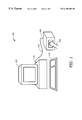
- FIG. 2 is a diagram illustrating a 3-D stereo vision inside the input unit 150 for inputting hand motion according to one embodiment of the invention.
- the input unit 150 includes a light source 210 , two cameras 220 and 230 , a processing element 235 , and a marker 240 .
- the light source 210 is any convenient light source to provide sufficient light for the camera.
- the light source is mounted inside an enclosed housing and is powered by any convenient power supply including the computer supply via the connection cable.
- the light source is any light source in the work space of the user.
- the two cameras 220 and 230 are any camera that can capture images of a moving object in real-time. Depending on the type of marker to be used, the cameras may capture gray level or color images. In one embodiment, the cameras 220 and 230 are video cameras that can operate with low ambient light. The two cameras 220 and 230 are positioned to point to the work space of the user hand 160 . The work space of the user hand 160 defines the 3-D space that the system can accept. The two cameras are preferably positioned according to a stereo imaging geometry as shown in FIG. 2 . The stereo imaging geometry allows the computation of the 3-D coordinates of the object.
- the marker 240 is any convenient object that is used to facilitate the detection of the movement of the user's hand or finger.
- the marker 240 is a specially designed object that can be worn at the tip of the user's finger.
- the marker 240 has unique features so that the processing of the images captured by the two cameras 220 and 230 can be performed quickly to identify the marker 240 . Examples of these unique features include color, shape, type of material, etc. If the marker 240 has some unique color, the camera imaging can be filtered by the appropriate color filter to separate the marker from other objects in the scene.
- the marker 240 is located at the intersection lines 245 and 247 from the two cameras 230 and 220 , respectively. As will be explained later, the 3-D coordinates of the marker 240 are determined by solving equations of the lines 245 and 247 .
- FIG. 3 is a diagram illustrating a 3-D stereo vision system 300 for inputting facial expressions and/or eye tracking according to one embodiment of the invention.
- the system 300 includes the computer 110 , the display monitor 120 , the keyboard 130 , an input entry device 310 , two cameras 320 and 330 targeting a user's head 340 and/or user's left and right eyes 325 and 335 .
- the computer 110 the display monitor 120 , and the keyboard 130 are described earlier.
- the input entry device 310 is any input entry device such as mouse, tablet digitizer, pen stylus, track ball, etc.
- the two cameras 320 and 330 are any two cameras that can capture the video images in real time.
- the two cameras 320 and 330 are configured to operate in normal ambient light.
- the two cameras are positioned in such a way that they can capture the images of the user's eyes 325 and 335 or user's head 340 within their field of view.
- the two cameras 320 and 330 are mounted on top of the display monitor 120 pointing toward the user's head in a stereo geometry.
- the systems shown in FIGS. 2 and 3 can be combined to provide a more complete 3-D navigation.
- the user can use the input unit 150 in FIG. 2 to provide normal 3-D input data and use head or eye movement in FIG. 3 to generate additional commands such as viewpoint modifications, rotation and translation of images, zoom and minification of images.
- the user can combine several data input entries to indicate an input action. For example, the user may use one hand in the input unit 150 to provide the normal 3-D input data and use another hand to enter another input data via a mouse or a keyboard.
- Examples of other additional input entry devices include a voice recognition system to process speech data, a heat sensing device, etc.
- Examples of other input events include clicking a mouse button, moving the mouse on the mouse pad, holding down the control key on the keyboard, uttering a command word, etc.
- FIG. 4 is a diagram illustrating a 3-D stereo geometry for 3-D coordinate computations according to one embodiment of the invention.
- the 3-D stereo geometry includes two point sources S1 and S2, two imaging planes 410 and 420 , the object point P(x, y, z), and two image points P1 and P2.
- the object P (x,y,z) is the object of interest as detected by the vision system.
- the object P may be the marker 240 in FIG. 2, the user's left and right eyes 325 and 335 in FIG. 3 or the user's head 340 as in FIG. 3 .
- the object of interest may be of some size, it is reduced to a point for simplicity.
- the object point may be some interesting and stable point of the object such as the centroid, corners, tip of the marker, etc.
- the two image points P1 and P2 are the images of the object P (x,y,z) as seen by the cameras.
- the image points P 1 and P 2 are formed by projecting the object point P on the image planes 410 and 420 , respectively. If the distance between the object point P and the cameras is sufficiently large compared to the focus lengths of the cameras, the position of the image points P 1 and P 2 can be estimated as the intersection points between the lines connecting the object point P to the camera focus points S 1 and S 2 and the corresponding image planes 410 and 420 .
- the imaging geometry may be calibrated at various camera positions so that various offsets or correction factors can be pre-determined for each object position. These offsets or correction factors can later be used to adjust the values as computed by the system.
- the process 500 obtains the real-time images of the object (Block 510 ). If the cameras provide the video signals, the process 500 performs video digitization to generate a digital image for each camera at each video frame (block 510 ).
- the image resolution depends on the particular implementation. Typical image resolution includes 320 ⁇ 240, 512 ⁇ 512, 640 ⁇ 512, 768 ⁇ 512. If the cameras provide direct digital data, the image digital data are stored in buffer memory for processing.
- the process 500 then performs object detection (Block 520 ).
- the object to be detected is the marker in the input unit 150 (FIG. 2 ), or the eyes 325 and 335 or the head 340 (FIG. 3 ).
- Object detection is performed using standard image processing techniques. Techniques such as edge detection, thresholding, color recognition, can be employed to identify the object.
- the process 500 determines the 3-D coordinates of the object point (Block 540 ).
- the determination of the 3-D coordinates is carried out by finding the intersection of the lines connecting the camera sources and the corresponding image object points on the image planes.
- FIG. 6A is a diagram illustrating one 3-D input pattern using finger motion according to one embodiment of the invention.
- the user moves its marker on his finger from position 610 to position 620 .
- This motion pattern may correspond to a specific command or may correspond to the exact 3-D movement that the user wants to navigate in the 3-D world.
- FIG. 6B is a diagram illustrating one 3-D input pattern using finger motion according to one embodiment of the invention.
- this pattern only the tip of the finger moves from position 630 to position 640 .
- This pattern corresponds to mainly a depth motion. Again, it may be used as a specific command or an actual motion.
- FIG. 6C is a diagram illustrating one 3-D input pattern using motion of two fingers according to one embodiment of the invention.
- This pattern involves the use of two markers at the original positions 650 and 660 .
- Each marker may have different unique features to facilitate the detection.
- the marker at position 650 may have a blue color while the marker at position 660 may have a red color.
- the pattern shows the movement of both markers to new positions 670 and 680 .
Abstract
The present invention is directed to a method and apparatus for providing three-dimensional (3-D) input data to a computer. A marker is moved in a 3-D work place. The marker has at least one unique feature distinctive from other objects in the 3-D work place. The movement of the marker in the 3-D work place is sensed by at least two sensors in a stereo imaging geometry to produce stereo images containing the marker. The stereo images are processed to produce marker images. The 3-D coordinates of the marker are computed from the marker images to provide the 3-D input data to the computer.
Description
1. Field of the Invention
This invention relates to computer systems. In particular, the invention relates to three-dimensional (3-D) input entry devices.
2. Description of Related Art
Three-dimensional (3-D) graphic and imaging systems have been popular for a number of years. High performance processors with 3-D capabilities have been developed for 3-D applications such as animation, visualization, games, and education.
In many interactive 3-D applications, the user needs to interact with the system in a 3-D world. The traditional input entry devices, e.g., mice, tablet digitizers, track balls, only provide two-dimensional (2-D) input information. For example, in a 3-D system having three coordinates (x, y, z), the 2-D input information includes only the (x, y) coordinates. The depth information (the z-dimension) is usually missing. The input data, therefore, does not represent sufficient information to fully utilize the 3-D world as generated or processed by the graphics or imaging programs.
There are a number of ways to process 3-D information in the system. The simplest way is to assume that the depth dimension is constant. In essence, this method ignores the depth information or assigns a predetermined depth dimension. This method is undesirable because it does not provide the user the means to change the depth dimension. Another way is to convert the 3-D world from the program to a 2-D world as seen by the user and process the 2-D input on this 2-D remapped world. This method introduces ambiguity in processing the data. Another way is to provide 3-D input devices and/or subsystems used in virtual reality systems such as gloves, head-mounted display. This method is expensive and requires complex hardware modifications.
Therefore, there is a need in the technology to provide a simple and efficient method to navigate in 3-D worlds.
The present invention is directed to a method and apparatus for providing three-dimensional (3-D) input data to a computer. A marker is moved in a 3-D work place. The marker has at least one unique feature distinctive from other objects in the 3-D work place. The movement of the marker in the 3-D work place is sensed by at least two sensors in a stereo imaging geometry to produce stereo images containing the marker. The stereo images are processed to produce marker images. The 3-D coordinates of the marker are computed from the marker images to provide the 3-D input data to the computer.
The features and advantages of the present invention will become apparent from the following detailed description of the present invention in which:
FIG. 1 is a diagram illustrating one embodiment of a system in accordance with the teachings of the invention.
FIG. 2 is a diagram illustrating a 3-D stereo vision for inputting hand motion according to one embodiment of the invention.
FIG. 3 is a diagram illustrating a 3-D stereo vision for inputting facial expressions and/or eye tracking according to one embodiment of the invention.
FIG. 4 is a diagram illustrating a 3-D stereo geometry for 3-D coordinate computations according to one embodiment of the invention.
FIG. 5 is a flow diagram illustrating a process to determine the 3-D input data according to one embodiment of the invention.
FIG. 6A is a diagram illustrating one 3-D input pattern using finger motion according to one embodiment of the invention.
FIG. 6B is a diagram illustrating one 3-D input pattern using finger motion according to one embodiment of the invention.
FIG. 6C is a diagram illustrating one 3-D input pattern using motion of two fingers according to one embodiment of the invention.
The present invention discloses a method and apparatus for navigating 3-D worlds. The technique uses stereo imaging to capture the 3-D information of a marker on the user hand. The 3-D coordinates of the marker are computed using 3-D camera geometry. Other markers including facial expressions, head and eye movements can also be used as 3-D input data. The invention provides a means for user to navigate the 3-D world as processed by the computer.
In the following description, for purposes of explanation, numerous details are set forth in order to provide a thorough understanding of the present invention. However, it will be apparent to one skilled in the art that these specific details are not required in order to practice the present invention. In other instances, well known electrical structures and circuits are shown in block diagram form in order not to obscure the present invention.
FIG. 1 is a diagram illustrating one embodiment of a system in accordance with the teachings of the invention. The system 100 includes a computer 110, a display monitor 120, a keyboard 130, an input unit 150 adapted for a user hand 160, and an interface cable 170.
The computer 110 is loaded with a 3-D processing program such as 3-D animation, game, education, and visualization. In one embodiment, the computer 110 is based on a high performance microprocessor, such as any type of Intel® microprocessor architecture. The computer 110 typically has interfaces to one or more input/output (I/O) devices such as display monitor 120, keyboard 130, mouse, and tablet digitizer. In one embodiment, the computer 110 has interfaces to the input unit 150 for receiving 3-D information.
The display monitor 120 displays the 3-D graphic or image data as processed by the computer 110. The display monitor 120 is any monitor, including cathode ray tube (CRT), a flat panel display, etc. The keyboard 130 provides key data entry to the computer 110. The keyboard 130 may also include other entry devices such as track ball and mouse pad.
The input unit 150 provides a housing for the 3-D input system which provides a work area for the user hand 160. In one embodiment, the input unit 150 includes a stereo camera system to determine the 3-D coordinates of a marker manipulated by the user. In this stereo imaging system, two cameras are installed inside the input unit 150. As is known by one skilled in the art, other configurations may be employed to provide stereo images. Examples of other configurations include those with more than two cameras or one camera occupying two locations. A light source illuminates the marker to be imaged by the stereo cameras. The marker can be conveniently worn on the user's finger. In this embodiment, for example, the input unit 150 includes a closed enclosure to avoid scattering of emitted light. If the light source is strong enough to enable the image capture of the marker, the enclosure may be partially open or even completely open. The input unit 150 is interfaced to the computer 110 via a communication interface cable 170.
The input unit 150 may be implemented as a stand-alone input unit or as a peripheral to the computer 110. In a stand-alone configuration, the input unit 150 has its own processor to performs the 3-D calculations and transmits the computed 3-D data to the computer 110 via the interface cable 170 In a peripheral configuration, the input unit 150 transmits the sensed information to the computer 110. As will be illustrated later, one type of sensor to be used in the input unit 150 is the camera. The information as generated by the camera is transmitted to the computer 110 via the cable 170. If the camera is a video camera generating video signal, the cable 170 will be a video cable. If the camera is a digital camera which can generate digital information directly, the cable 170 may be a digital cable connected to the computer 110 via a communication interface port such as a serial, parallel, or universal serial bus (USB) port.
FIG. 2 is a diagram illustrating a 3-D stereo vision inside the input unit 150 for inputting hand motion according to one embodiment of the invention. The input unit 150 includes a light source 210, two cameras 220 and 230, a processing element 235, and a marker 240.
The light source 210 is any convenient light source to provide sufficient light for the camera. In one embodiment, the light source is mounted inside an enclosed housing and is powered by any convenient power supply including the computer supply via the connection cable. In another embodiment, the light source is any light source in the work space of the user.
The two cameras 220 and 230 are any camera that can capture images of a moving object in real-time. Depending on the type of marker to be used, the cameras may capture gray level or color images. In one embodiment, the cameras 220 and 230 are video cameras that can operate with low ambient light. The two cameras 220 and 230 are positioned to point to the work space of the user hand 160. The work space of the user hand 160 defines the 3-D space that the system can accept. The two cameras are preferably positioned according to a stereo imaging geometry as shown in FIG. 2. The stereo imaging geometry allows the computation of the 3-D coordinates of the object.
The processing element 235 receives the stereo images from the two cameras 220 and 230 and processes the stereo images to produce the marker images which contain the images of the marker from two stereo positions. The processing element 235 may be located inside the input unit 150 or as part of the computer 110. If the cameras 220 and 230 are analog cameras sending out video signals, the processing element 235 may include a video-to-digital converter such as a frame grabber to convert the analog video signal into digital data. If the cameras 220 and 230 are digital cameras, the processing element 235 can process the image data directly. The processing element 235 may contain memory to store the image data and a processor with some computational power to process the image data.
The marker 240 is any convenient object that is used to facilitate the detection of the movement of the user's hand or finger. In one embodiment, the marker 240 is a specially designed object that can be worn at the tip of the user's finger. The marker 240 has unique features so that the processing of the images captured by the two cameras 220 and 230 can be performed quickly to identify the marker 240. Examples of these unique features include color, shape, type of material, etc. If the marker 240 has some unique color, the camera imaging can be filtered by the appropriate color filter to separate the marker from other objects in the scene. The marker 240 is located at the intersection lines 245 and 247 from the two cameras 230 and 220, respectively. As will be explained later, the 3-D coordinates of the marker 240 are determined by solving equations of the lines 245 and 247.
FIG. 3 is a diagram illustrating a 3-D stereo vision system 300 for inputting facial expressions and/or eye tracking according to one embodiment of the invention. The system 300 includes the computer 110, the display monitor 120, the keyboard 130, an input entry device 310, two cameras 320 and 330 targeting a user's head 340 and/or user's left and right eyes 325 and 335.
The computer 110, the display monitor 120, and the keyboard 130 are described earlier. The input entry device 310 is any input entry device such as mouse, tablet digitizer, pen stylus, track ball, etc.
The two cameras 320 and 330 are any two cameras that can capture the video images in real time. In one embodiment, the two cameras 320 and 330 are configured to operate in normal ambient light. The two cameras are positioned in such a way that they can capture the images of the user's eyes 325 and 335 or user's head 340 within their field of view. In one embodiment, the two cameras 320 and 330 are mounted on top of the display monitor 120 pointing toward the user's head in a stereo geometry.
In this 3-D system, the 3-D input data are provided by the movement of the user's eyes or head. By tracking the eye or head movement, the system will determine the view point of the user and process the 3-D images accordingly. In a typical application, the image displayed on the display monitor 120 represents the scene as seen by the user. When the user moves his or her eyes in a direction to focus on a certain location of the image, the system will display the region of interest corresponding to the location as focused by the user. Similarly, the movement of the user's head 340 also provides additional 3-D view points.
The system 300 can be configured to operate in a number of modes. In one mode, the system 300 tracks the movement of the user's eyes 325 and 335 and the user's head 340 independently. In another mode, the system tracks the movements of the user's eyes 325 and 335 and the user's head 340 in an integrated manner. For example, the user's head 340 may provide the depth and rotation parameters while the user's eyes 325 and 335 may provide the translation parameters. Yet in another mode, the system 300 may simply track the movement of the user's head 340 based on the movement of the eyes. By tracking the head movement, the system 300 may determine certain gestures or expressions. For example, the system may determine a vertical movement of the user's head 340 as a nod, indicating agreement, or a horizontal movement of the user's head 340 as a shake, indicating disagreement. In this case, special markers may be worn by the user to facilitate the detection of the movement such as eye glasses with predetermined color, shape, and type of material.
The systems shown in FIGS. 2 and 3 can be combined to provide a more complete 3-D navigation. The user can use the input unit 150 in FIG. 2 to provide normal 3-D input data and use head or eye movement in FIG. 3 to generate additional commands such as viewpoint modifications, rotation and translation of images, zoom and minification of images. In addition, the user can combine several data input entries to indicate an input action. For example, the user may use one hand in the input unit 150 to provide the normal 3-D input data and use another hand to enter another input data via a mouse or a keyboard. Examples of other additional input entry devices include a voice recognition system to process speech data, a heat sensing device, etc. Examples of other input events include clicking a mouse button, moving the mouse on the mouse pad, holding down the control key on the keyboard, uttering a command word, etc.
FIG. 4 is a diagram illustrating a 3-D stereo geometry for 3-D coordinate computations according to one embodiment of the invention. The 3-D stereo geometry includes two point sources S1 and S2, two imaging planes 410 and 420, the object point P(x, y, z), and two image points P1 and P2.
The two point sources S1 and S2 represent the focus points of the two cameras in the stereo configuration. These are the two cameras 220 and 230 in FIG. 2, or the two cameras 320 and 330 in FIG. 3. The two imaging planes 410 and 420 are the image planes inside the corresponding cameras. The image planes 410 and 420 essentially contain the images as captured by the image sensors. These image planes therefore correspond to the images as provided by the cameras either in video or digital form.
The object P (x,y,z) is the object of interest as detected by the vision system. The object P may be the marker 240 in FIG. 2, the user's left and right eyes 325 and 335 in FIG. 3 or the user's head 340 as in FIG. 3. Although the object of interest may be of some size, it is reduced to a point for simplicity. The object point may be some interesting and stable point of the object such as the centroid, corners, tip of the marker, etc.
The two image points P1 and P2 are the images of the object P (x,y,z) as seen by the cameras. From optical geometry, the image points P1 and P2 are formed by projecting the object point P on the image planes 410 and 420, respectively. If the distance between the object point P and the cameras is sufficiently large compared to the focus lengths of the cameras, the position of the image points P1 and P2 can be estimated as the intersection points between the lines connecting the object point P to the camera focus points S1 and S2 and the corresponding image planes 410 and 420. To increase accuracy, the imaging geometry may be calibrated at various camera positions so that various offsets or correction factors can be pre-determined for each object position. These offsets or correction factors can later be used to adjust the values as computed by the system.
To determine the 3-D coordinates of the object point P, it is therefore necessary to determine the equation of the two lines connecting P1 and S1 and P2 and S2, and then equating the two equations to find the coordinates of the intersection point P.
Using an arbitrary 3-D coordinate system, the coordinates of S1, P1, S2, and P2 are expressed in terms of this coordinate system. Since S1, P1, S2 and P2 are known, the equations of the two lines can be obtained easily. These equations are parametric equations. Since P is the intersection point of S1P1 and S2P2, it should have the same (x,y,z) coordinates on the two lines. Equating the 3 pairs of equations in the three dimensions x, y, and z will give the solutions for the (x,y,z) coordinates of the point P.
FIG. 5 is a flow diagram illustrating a process 500 to determine the 3-D input data according to one embodiment of the invention.
Upon start, the process 500 obtains the real-time images of the object (Block 510). If the cameras provide the video signals, the process 500 performs video digitization to generate a digital image for each camera at each video frame (block 510). The image resolution depends on the particular implementation. Typical image resolution includes 320×240, 512×512, 640×512, 768×512. If the cameras provide direct digital data, the image digital data are stored in buffer memory for processing.
The process 500 then performs object detection (Block 520). The object to be detected is the marker in the input unit 150 (FIG. 2), or the eyes 325 and 335 or the head 340 (FIG. 3). Object detection is performed using standard image processing techniques. Techniques such as edge detection, thresholding, color recognition, can be employed to identify the object.
The process 500 then determines the object point based on the detected object (Block 530). In some cases, the process 500 performs the operations in blocks 520 and 530 at the same time. Many techniques are available to determine the object point. Perhaps the simplest is to compute the centroid of the region of the pixels belonging to the object. Another technique is to locate points having high curvature such as corners of the object if the object is known to have sharp corners. Another technique is to determine the point having the highest edge activities. Additional processing may be performed to ensure reliable detection. Examples of these additional processes include trajectory smoothing, offset correction, calibration error adjustments, etc.
Then the process 500 determines the 3-D coordinates of the object point (Block 540). The determination of the 3-D coordinates is carried out by finding the intersection of the lines connecting the camera sources and the corresponding image object points on the image planes.
The process 500 then transmits the computed 3-D data to the system (Block 550). The process 500 then terminates.
FIG. 6A is a diagram illustrating one 3-D input pattern using finger motion according to one embodiment of the invention. In this pattern, the user moves its marker on his finger from position 610 to position 620. This motion pattern may correspond to a specific command or may correspond to the exact 3-D movement that the user wants to navigate in the 3-D world.
FIG. 6B is a diagram illustrating one 3-D input pattern using finger motion according to one embodiment of the invention. In this pattern, only the tip of the finger moves from position 630 to position 640. This pattern corresponds to mainly a depth motion. Again, it may be used as a specific command or an actual motion.
FIG. 6C is a diagram illustrating one 3-D input pattern using motion of two fingers according to one embodiment of the invention. This pattern involves the use of two markers at the original positions 650 and 660. Each marker may have different unique features to facilitate the detection. For example, the marker at position 650 may have a blue color while the marker at position 660 may have a red color. The pattern shows the movement of both markers to new positions 670 and 680.
The movement patterns shown in FIGS. 6A, 6B, and 6C merely illustrate some examples that the user can navigate a 3-D world using 3-D movement with a marker or markers.
The present invention therefore provides a method and apparatus for navigation in 3-D world by providing simple and efficient 3-D vision system. The technique does not require major hardware modifications and can be implemented using commercially off-the-shelf hardware.
While this invention has been described with reference to illustrative embodiments, this description is not intended to be construed in a limiting sense. Various modifications of the illustrative embodiments, as well as other embodiments of the invention, which are apparent to persons skilled in the art to which the invention pertains are deemed to lie within the spirit and scope of the invention.
Claims (35)
1. A method comprising:
moving a marker in a work place, the marker having at least one unique feature distinctive from other objects in the work place;
sensing movement of the marker in the work place by at least two sensors in a stereo imaging geometry using the at least one unique feature of the marker to produce stereo images containing the marker;
processing the stereo images to produce marker images; and
computing 3-D coordinates of the marker from the marker images to produce a three-dimensional (3-D) input data using a point of intersection from the corresponding stereo images, the 3-D input data being combined with an entry from a device to indicate an input action.
2. The method of claim 1 further comprising:
illuminating the marker by a light source.
3. The method of claim 1 wherein computing the 3-D coordinates includes:
determining image points corresponding to the marker images;
determining lines connecting the image points and the at least two sensors through corresponding images planes in the stereo imaging geometry; and
determining a point of intersection between the lines, the point of intersection providing the 3-D coordinates.
4. The method of claim 3 wherein determining image points comprises:
detecting an object representing the marker in the marker images;
determining an object point corresponding to the object.
5. The method of claim 4 wherein the object point includes a centroid point, an edge point, and a high curvature point.
6. The method of claim 1 wherein the at least one unique feature includes a predetermined color, a predetermined shape, a predetermined size, and a predetermined relative location.
7. The method of claim 1 wherein the marker is mounted on a finger of a users' hand.
8. The method of claim 1 wherein the work place is enclosed in an input unit.
9. The method of claim 1 wherein the sensors are cameras.
10. The method of claim 1 wherein the marker includes user's eyes, user's facial expressions, and user's head.
11. An apparatus comprising:
at least two sensors to sense movement of a marker in a stereo imaging geometry to produce stereo images containing the marker using at least one unique feature of the marker distinctive from other objects in a work place; and
a processing element coupled to the at least two sensors to process the stereo images, the processing element computing 3-D coordinates of the marker from marker images produced by the stereo images to produce the 3-D input data using a point of intersection from the corresponding stereo images, the 3-D input data being combined with an entry from a device to indicate an input action.
12. The apparatus of claim 11 further comprising:
a light source to illuminate the marker.
13. The apparatus of claim 11 wherein the processing element computes the 3-D coordinates by
determining image points corresponding to the marker images;
determining lines connecting the image points and the at least two sensors through corresponding images planes in the stereo imaging geometry; and
determining a point of intersection between the lines, the point of intersection providing the 3-D coordinates.
14. The apparatus of claim 13 wherein the processing element further
detects an object representing the marker in the marker images; and
determines an object point corresponding to the object.
15. The apparatus of claim 14 wherein the object point includes a centroid point, an edge point, and a high curvature point.
16. The apparatus of claim 11 wherein the at least one unique feature includes a predetermined color, a predetermined shape, a predetermined size, and a predetermined relative location.
17. The apparatus of claim 11 wherein the marker is mounted on a finger of a users' hand.
18. The apparatus of claim 11 wherein the work place is enclosed in an input unit.
19. The apparatus of claim 11 wherein the sensors are cameras.
20. The apparatus of claim 11 wherein the marker includes user's eyes, user's facial expressions, and user's head.
21. A system comprising:
a computer to provide display data corresponding to three-dimensional (3-D) input data entered by a user; and
an input unit coupled to the computer to produce the 3-D input data, the input unit including:
at least two sensors to sense movement of a marker in a stereo imaging geometry to produce stereo images containing the marker using at least one unique feature of the marker distinctive from other objects in a work place, and
a processing element coupled to the at least two sensors to process the stereo images, the processing element computing 3-D coordinates of the marker from marker images produced by the stereo images to provide the 3-D input data to a computer using a point of intersection from the corresponding stereo images, the 3-D input data being combined with an entry from a device to indicate an input action.
22. The system of claim 21 wherein the input unit further comprises:
a light source to illuminate the marker.
23. The system of claim 21 wherein the processing element computes the 3-D coordinates by
determining image points corresponding to the marker images;
determining lines connecting the image points and the at least two sensors through corresponding images planes in the stereo imaging geometry; and
determining a point of intersection between the lines, the point of intersection providing the 3-D coordinates.
24. The system of claim 23 wherein the processing element further
detects an object representing the marker in the marker images; and
determines an object point corresponding to the object.
25. The system of claim 24 wherein the object point includes a centroid point, an edge point, and a high curvature point.
26. The system of claim 21 wherein the at least one unique feature includes a predetermined color, a predetermined shape, a predetermined size, and a predetermined relative location.
27. The system of claim 21 wherein the marker is mounted on a finger of a users' hand.
28. The system of claim 21 wherein the marker includes user's eyes, user's facial expressions, and user's head.
29. The system of claim 21 further comprises an entry device coupled to the computer to provide an input entry entered by the user, the input entry being combined with the 3-D input data to define an input action.
30. The method of claim 1 wherein the device is one of a keyboard, a mouse, a voice recognition system, and a heat sensing element.
31. The method of claim 30 wherein the entry is generated by one of clicking a mouse button, moving a mouse on a mouse pad, holding down a control key on a keyboard, and uttering a command word.
32. The apparatus of claim 11 wherein the device is one of a keyboard, a mouse, a voice recognition system, and a heat sensing element.
33. The apparatus of claim 32 wherein the entry is generated by one of clicking a mouse button, moving a mouse on a mouse pad, holding down a control key on a keyboard, and uttering a command word.
34. The system of claim 21 wherein the device is one of a keyboard, a mouse, a voice recognition system, and a heat sensing element.
35. The system of claim 34 wherein the entry is generated by one of clicking a mouse button, moving a mouse on a mouse pad, holding down a control key on a keyboard, and uttering a command word.
Priority Applications (4)
| Application Number | Priority Date | Filing Date | Title |
|---|---|---|---|
| US09/123,965 US6198485B1 (en) | 1998-07-29 | 1998-07-29 | Method and apparatus for three-dimensional input entry |
| TW088112018A TW452723B (en) | 1998-07-29 | 1999-07-15 | Method and apparatus for three-dimensional input entry |
| PCT/US1999/016582 WO2000007148A1 (en) | 1998-07-29 | 1999-07-21 | Method and apparatus for three-dimensional input entry |
| AU52223/99A AU5222399A (en) | 1998-07-29 | 1999-07-21 | Method and apparatus for three-dimensional input entry |
Applications Claiming Priority (1)
| Application Number | Priority Date | Filing Date | Title |
|---|---|---|---|
| US09/123,965 US6198485B1 (en) | 1998-07-29 | 1998-07-29 | Method and apparatus for three-dimensional input entry |
Publications (1)
| Publication Number | Publication Date |
|---|---|
| US6198485B1 true US6198485B1 (en) | 2001-03-06 |
Family
ID=22411973
Family Applications (1)
| Application Number | Title | Priority Date | Filing Date |
|---|---|---|---|
| US09/123,965 Expired - Lifetime US6198485B1 (en) | 1998-07-29 | 1998-07-29 | Method and apparatus for three-dimensional input entry |
Country Status (4)
| Country | Link |
|---|---|
| US (1) | US6198485B1 (en) |
| AU (1) | AU5222399A (en) |
| TW (1) | TW452723B (en) |
| WO (1) | WO2000007148A1 (en) |
Cited By (100)
| Publication number | Priority date | Publication date | Assignee | Title |
|---|---|---|---|---|
| WO2001054110A1 (en) * | 2000-01-18 | 2001-07-26 | The Trustees Of The University Of Pennsylvania | Vision-based human computer interface system |
| US20020012014A1 (en) * | 2000-06-01 | 2002-01-31 | Olympus Optical Co., Ltd. | Operation input apparatus using sensor attachable to operator's hand |
| US20020041327A1 (en) * | 2000-07-24 | 2002-04-11 | Evan Hildreth | Video-based image control system |
| US20020113756A1 (en) * | 2000-09-25 | 2002-08-22 | Mihran Tuceryan | System and method for calibrating a stereo optical see-through head-mounted display system for augmented reality |
| US20020118274A1 (en) * | 2001-01-31 | 2002-08-29 | Akira Yahashi | Three-dimensional measuring method and system |
| US20030012408A1 (en) * | 2001-05-09 | 2003-01-16 | Jean-Yves Bouguet | Method and system using a data-driven model for monocular face tracking |
| US20030067538A1 (en) * | 2001-10-04 | 2003-04-10 | Myers Kenneth J. | System and method for three-dimensional data acquisition |
| US20030067537A1 (en) * | 2001-10-04 | 2003-04-10 | Myers Kenneth J. | System and method for three-dimensional data acquisition |
| US6654001B1 (en) * | 2002-09-05 | 2003-11-25 | Kye Systems Corp. | Hand-movement-sensing input device |
| WO2004057450A1 (en) * | 2002-12-23 | 2004-07-08 | Universita' Degli Studi Di Firenze | Hand pointing apparatus |
| US20040160420A1 (en) * | 2003-02-19 | 2004-08-19 | Izhak Baharav | Electronic device having an image-based data input system |
| US20050166163A1 (en) * | 2004-01-23 | 2005-07-28 | Chang Nelson L.A. | Systems and methods of interfacing with a machine |
| US20060036944A1 (en) * | 2004-08-10 | 2006-02-16 | Microsoft Corporation | Surface UI for gesture-based interaction |
| EP1645921A1 (en) * | 2004-10-05 | 2006-04-12 | FEHLINGS AUTOMATION GmbH | Monitoring of the motion of a human hand or a manually handled part |
| US20060076472A1 (en) * | 2004-10-08 | 2006-04-13 | Dialog Semiconductor Gmbh | Single chip stereo imaging system with dual array design |
| WO2006054207A1 (en) * | 2004-11-16 | 2006-05-26 | Koninklijke Philips Electronics N.V. | Touchless manipulation of images for regional enhancement |
| US20060202953A1 (en) * | 1997-08-22 | 2006-09-14 | Pryor Timothy R | Novel man machine interfaces and applications |
| WO2006101942A2 (en) * | 2005-03-16 | 2006-09-28 | Lc Technologies, Inc. | Systems and methods for eye-operated three-dimensional object location |
| US20070136064A1 (en) * | 2003-04-16 | 2007-06-14 | Carroll David W | Mobile personal computer with movement sensor |
| EP1851750A2 (en) * | 2005-02-08 | 2007-11-07 | Oblong Industries, Inc. | System and method for genture based control system |
| KR100811460B1 (en) | 2007-02-01 | 2008-03-10 | 강원대학교산학협력단 | Vibrotactile mouse device, and vibrotactile mouse system |
| US20090146951A1 (en) * | 2007-12-07 | 2009-06-11 | Robert Welland | User Interface Devices |
| US20090254855A1 (en) * | 2008-04-08 | 2009-10-08 | Sony Ericsson Mobile Communications, Ab | Communication terminals with superimposed user interface |
| US20090278797A1 (en) * | 2008-05-09 | 2009-11-12 | Inventec Corporation | Method and system for operating personal computer through motion recognition |
| WO2009157792A1 (en) * | 2008-06-24 | 2009-12-30 | Rurin Oleg Stanislavovich | Method for producing an effect on virtual objects |
| USD616486S1 (en) | 2008-10-20 | 2010-05-25 | X6D Ltd. | 3D glasses |
| US20100134612A1 (en) * | 1997-08-22 | 2010-06-03 | Timothy Pryor | Method for enhancing well-being of a small child or baby |
| US20100149636A1 (en) * | 2008-11-17 | 2010-06-17 | Macnaughton Boyd | Housing And Frame For 3D Glasses |
| US20100190610A1 (en) * | 2000-03-07 | 2010-07-29 | Pryor Timothy R | Camera based interactive exercise |
| CN101807115A (en) * | 2010-04-07 | 2010-08-18 | 友达光电股份有限公司 | Interactive stereo display system and distance calculating method |
| US20110080360A1 (en) * | 2009-10-02 | 2011-04-07 | Dedo Interactive Inc. | Universal touch input driver |
| WO2011045786A2 (en) | 2009-10-13 | 2011-04-21 | Rami Parham | Wearable device for generating input for computerized systems |
| US20110148931A1 (en) * | 2009-12-18 | 2011-06-23 | Samsung Electronics Co. Ltd. | Apparatus and method for controlling size of display data in portable terminal |
| WO2011104709A2 (en) | 2010-02-23 | 2011-09-01 | Rami Parham | A system for projecting content to a display surface having user-controlled size, shape and location/direction and apparatus and methods useful in conjunction therewith |
| USD646451S1 (en) | 2009-03-30 | 2011-10-04 | X6D Limited | Cart for 3D glasses |
| WO2011127646A1 (en) * | 2010-04-13 | 2011-10-20 | Nokia Corporation | An apparatus, method, computer program and user interface |
| USD650956S1 (en) | 2009-05-13 | 2011-12-20 | X6D Limited | Cart for 3D glasses |
| USD652860S1 (en) | 2008-10-20 | 2012-01-24 | X6D Limited | 3D glasses |
| CN102460563A (en) * | 2009-05-27 | 2012-05-16 | 美国亚德诺半导体公司 | Position measurement systems using position sensitive detectors |
| RU2451982C1 (en) * | 2008-06-24 | 2012-05-27 | Олег Станиславович Рурин | Method for producing effect on virtual objects |
| USD662965S1 (en) | 2010-02-04 | 2012-07-03 | X6D Limited | 3D glasses |
| USD664183S1 (en) | 2010-08-27 | 2012-07-24 | X6D Limited | 3D glasses |
| USD666663S1 (en) | 2008-10-20 | 2012-09-04 | X6D Limited | 3D glasses |
| USD669522S1 (en) | 2010-08-27 | 2012-10-23 | X6D Limited | 3D glasses |
| US8306635B2 (en) | 2001-03-07 | 2012-11-06 | Motion Games, Llc | Motivation and enhancement of physical and mental exercise, rehabilitation, health and social interaction |
| USD671590S1 (en) | 2010-09-10 | 2012-11-27 | X6D Limited | 3D glasses |
| US20120314022A1 (en) * | 2011-06-13 | 2012-12-13 | Samsung Electronics Co., Ltd. | Display apparatus and method for controlling display apparatus and remote controller |
| USD672804S1 (en) | 2009-05-13 | 2012-12-18 | X6D Limited | 3D glasses |
| JP2013047978A (en) * | 2005-02-08 | 2013-03-07 | Oblong Industries Inc | System and method for gesture based control system |
| US8542326B2 (en) | 2008-11-17 | 2013-09-24 | X6D Limited | 3D shutter glasses for use with LCD displays |
| USD692941S1 (en) | 2009-11-16 | 2013-11-05 | X6D Limited | 3D glasses |
| US8614668B2 (en) | 1997-08-22 | 2013-12-24 | Motion Games, Llc | Interactive video based games using objects sensed by TV cameras |
| US8654198B2 (en) | 1999-05-11 | 2014-02-18 | Timothy R. Pryor | Camera based interaction and instruction |
| US20140085177A1 (en) * | 2012-09-21 | 2014-03-27 | Nokia Corporation | Method and apparatus for responding to input based upon relative finger position |
| US20140098198A1 (en) * | 2012-10-09 | 2014-04-10 | Electronics And Telecommunications Research Institute | Apparatus and method for eye tracking |
| US20140111631A1 (en) * | 2012-10-22 | 2014-04-24 | Hon Hai Precision Industry Co., Ltd. | Auxiliary equipment and method for assisting usage of eyedropper |
| US20140152628A1 (en) * | 2009-10-06 | 2014-06-05 | Cherif Atia Algreatly | Computer input device for hand-held devices |
| CN103998316A (en) * | 2011-12-29 | 2014-08-20 | 英特尔公司 | Systems, methods, and apparatus for controlling gesture initiation and termination |
| USD711959S1 (en) | 2012-08-10 | 2014-08-26 | X6D Limited | Glasses for amblyopia treatment |
| US8872910B1 (en) * | 2009-06-04 | 2014-10-28 | Masoud Vaziri | Method and apparatus for a compact and high resolution eye-view recorder |
| USRE45394E1 (en) | 2008-10-20 | 2015-03-03 | X6D Limited | 3D glasses |
| US9117138B2 (en) | 2012-09-05 | 2015-08-25 | Industrial Technology Research Institute | Method and apparatus for object positioning by using depth images |
| US9265458B2 (en) | 2012-12-04 | 2016-02-23 | Sync-Think, Inc. | Application of smooth pursuit cognitive testing paradigms to clinical drug development |
| US9317128B2 (en) | 2009-04-02 | 2016-04-19 | Oblong Industries, Inc. | Remote devices used in a markerless installation of a spatial operating environment incorporating gestural control |
| US9354718B2 (en) | 2010-12-22 | 2016-05-31 | Zspace, Inc. | Tightly coupled interactive stereo display |
| US9380976B2 (en) | 2013-03-11 | 2016-07-05 | Sync-Think, Inc. | Optical neuroinformatics |
| US20160210411A1 (en) * | 2015-01-16 | 2016-07-21 | University Of Maryland Baltmore County | Annotation of endoscopic video using gesture and voice commands |
| US9471149B2 (en) | 2009-04-02 | 2016-10-18 | Oblong Industries, Inc. | Control system for navigating a principal dimension of a data space |
| US9471147B2 (en) | 2006-02-08 | 2016-10-18 | Oblong Industries, Inc. | Control system for navigating a principal dimension of a data space |
| US9495228B2 (en) | 2006-02-08 | 2016-11-15 | Oblong Industries, Inc. | Multi-process interactive systems and methods |
| US9495013B2 (en) | 2008-04-24 | 2016-11-15 | Oblong Industries, Inc. | Multi-modal gestural interface |
| US20170102859A1 (en) * | 2000-05-22 | 2017-04-13 | F. Poszat Hu, Llc | Three dimensional human-computer interface |
| US9684380B2 (en) | 2009-04-02 | 2017-06-20 | Oblong Industries, Inc. | Operating environment with gestural control and multiple client devices, displays, and users |
| US9727790B1 (en) * | 2010-06-04 | 2017-08-08 | Masoud Vaziri | Method and apparatus for a wearable computer with natural user interface |
| US9740293B2 (en) | 2009-04-02 | 2017-08-22 | Oblong Industries, Inc. | Operating environment with gestural control and multiple client devices, displays, and users |
| US9740922B2 (en) | 2008-04-24 | 2017-08-22 | Oblong Industries, Inc. | Adaptive tracking system for spatial input devices |
| US9779131B2 (en) | 2008-04-24 | 2017-10-03 | Oblong Industries, Inc. | Detecting, representing, and interpreting three-space input: gestural continuum subsuming freespace, proximal, and surface-contact modes |
| DE102016206529A1 (en) | 2016-04-19 | 2017-10-19 | Robert Bosch Gmbh | Assembly workstation with positioning device |
| US9804902B2 (en) | 2007-04-24 | 2017-10-31 | Oblong Industries, Inc. | Proteins, pools, and slawx in processing environments |
| US20170330042A1 (en) * | 2010-06-04 | 2017-11-16 | Masoud Vaziri | Method and apparatus for an eye tracking wearable computer |
| US9823747B2 (en) | 2006-02-08 | 2017-11-21 | Oblong Industries, Inc. | Spatial, multi-modal control device for use with spatial operating system |
| US9880619B2 (en) | 2010-02-23 | 2018-01-30 | Muy Interactive Ltd. | Virtual reality system with a finger-wearable control |
| US9910497B2 (en) | 2006-02-08 | 2018-03-06 | Oblong Industries, Inc. | Gestural control of autonomous and semi-autonomous systems |
| US9933852B2 (en) | 2009-10-14 | 2018-04-03 | Oblong Industries, Inc. | Multi-process interactive systems and methods |
| US9952673B2 (en) | 2009-04-02 | 2018-04-24 | Oblong Industries, Inc. | Operating environment comprising multiple client devices, multiple displays, multiple users, and gestural control |
| US9990046B2 (en) | 2014-03-17 | 2018-06-05 | Oblong Industries, Inc. | Visual collaboration interface |
| US10146331B2 (en) * | 2014-11-28 | 2018-12-04 | Ricoh Company, Ltd. | Information processing system for transforming coordinates of a position designated by a pointer in a virtual image to world coordinates, information processing apparatus, and method of transforming coordinates |
| US10178353B2 (en) * | 2011-03-02 | 2019-01-08 | Limited Liability Company “Disicon” | System and method for video surveillance of a forest |
| US10410359B2 (en) * | 2003-02-11 | 2019-09-10 | Sony Interactive Entertainment Inc. | Methods for capturing images of markers of a person to control interfacing with an application |
| US10529302B2 (en) | 2016-07-07 | 2020-01-07 | Oblong Industries, Inc. | Spatially mediated augmentations of and interactions among distinct devices and applications via extended pixel manifold |
| US10642364B2 (en) | 2009-04-02 | 2020-05-05 | Oblong Industries, Inc. | Processing tracking and recognition data in gestural recognition systems |
| US10824238B2 (en) | 2009-04-02 | 2020-11-03 | Oblong Industries, Inc. | Operating environment with gestural control and multiple client devices, displays, and users |
| US10990454B2 (en) | 2009-10-14 | 2021-04-27 | Oblong Industries, Inc. | Multi-process interactive systems and methods |
| US11042991B2 (en) * | 2013-11-27 | 2021-06-22 | Google Llc | Determining multiple camera positions from multiple videos |
| US11120254B2 (en) * | 2017-03-29 | 2021-09-14 | Beijing Sensetime Technology Development Co., Ltd. | Methods and apparatuses for determining hand three-dimensional data |
| EP3879403A1 (en) | 2020-03-12 | 2021-09-15 | Robert Bosch GmbH | Workstation with schedule for data processing tools |
| US11367164B1 (en) | 2009-06-04 | 2022-06-21 | Masoud Vaziri | Method and apparatus for super resolution imaging and eye tracking devices |
| US11432723B1 (en) | 2009-06-04 | 2022-09-06 | Masoud Vaziri | Method and apparatus for a compact and high resolution mind-view communicator |
| US11450113B1 (en) * | 2009-06-04 | 2022-09-20 | Masoud Vaziri | Method and apparatus for a wearable computer |
| US11800244B1 (en) | 2022-08-13 | 2023-10-24 | Mojtaba Vaziri | Method and apparatus for an imaging device |
Families Citing this family (12)
| Publication number | Priority date | Publication date | Assignee | Title |
|---|---|---|---|---|
| GB0121536D0 (en) * | 2001-09-06 | 2001-10-24 | 4D Technology Systems Ltd | Controlling electronic device |
| KR100560030B1 (en) * | 2001-11-22 | 2006-03-13 | 고나미 가부시끼가이샤 | Input apparatus of billiard game, billiard game system, input apparatus for game and computer readable memory medium |
| CN101542420A (en) * | 2006-11-27 | 2009-09-23 | 皇家飞利浦电子股份有限公司 | 3D control of data processing through handheld pointing device |
| US9285459B2 (en) | 2008-05-09 | 2016-03-15 | Analog Devices, Inc. | Method of locating an object in 3D |
| US9746544B2 (en) | 2008-12-03 | 2017-08-29 | Analog Devices, Inc. | Position measurement systems using position sensitive detectors |
| US9304202B2 (en) | 2009-05-27 | 2016-04-05 | Analog Devices, Inc. | Multiuse optical sensor |
| EP2390761A1 (en) * | 2010-05-26 | 2011-11-30 | Advanced Digital Broadcast S.A. | A method and system for selecting an item in a three dimensional space |
| US9702690B2 (en) | 2011-12-19 | 2017-07-11 | Analog Devices, Inc. | Lens-less optical position measuring sensor |
| US9043146B2 (en) * | 2013-06-19 | 2015-05-26 | The Boeing Company | Systems and methods for tracking location of movable target object |
| CN103793060B (en) * | 2014-02-14 | 2017-07-28 | 杨智 | A kind of user interactive system and method |
| CN105744254B (en) * | 2014-12-30 | 2017-12-29 | 钰立微电子股份有限公司 | Correct guidance system and correct the operating method of guidance system |
| US11674797B2 (en) | 2020-03-22 | 2023-06-13 | Analog Devices, Inc. | Self-aligned light angle sensor using thin metal silicide anodes |
Citations (7)
| Publication number | Priority date | Publication date | Assignee | Title |
|---|---|---|---|---|
| US4935728A (en) * | 1985-01-02 | 1990-06-19 | Altra Corporation | Computer control |
| US5305012A (en) * | 1992-04-15 | 1994-04-19 | Reveo, Inc. | Intelligent electro-optical system and method for automatic glare reduction |
| US5616078A (en) * | 1993-12-28 | 1997-04-01 | Konami Co., Ltd. | Motion-controlled video entertainment system |
| US5636334A (en) * | 1994-01-28 | 1997-06-03 | Casio Computer Co., Ltd. | Three-dimensional image creation devices |
| US5748199A (en) * | 1995-12-20 | 1998-05-05 | Synthonics Incorporated | Method and apparatus for converting a two dimensional motion picture into a three dimensional motion picture |
| US5818424A (en) * | 1995-10-19 | 1998-10-06 | International Business Machines Corporation | Rod shaped device and data acquisition apparatus for determining the position and orientation of an object in space |
| US6064354A (en) * | 1998-07-01 | 2000-05-16 | Deluca; Michael Joseph | Stereoscopic user interface method and apparatus |
-
1998
- 1998-07-29 US US09/123,965 patent/US6198485B1/en not_active Expired - Lifetime
-
1999
- 1999-07-15 TW TW088112018A patent/TW452723B/en not_active IP Right Cessation
- 1999-07-21 WO PCT/US1999/016582 patent/WO2000007148A1/en active Application Filing
- 1999-07-21 AU AU52223/99A patent/AU5222399A/en not_active Abandoned
Patent Citations (7)
| Publication number | Priority date | Publication date | Assignee | Title |
|---|---|---|---|---|
| US4935728A (en) * | 1985-01-02 | 1990-06-19 | Altra Corporation | Computer control |
| US5305012A (en) * | 1992-04-15 | 1994-04-19 | Reveo, Inc. | Intelligent electro-optical system and method for automatic glare reduction |
| US5616078A (en) * | 1993-12-28 | 1997-04-01 | Konami Co., Ltd. | Motion-controlled video entertainment system |
| US5636334A (en) * | 1994-01-28 | 1997-06-03 | Casio Computer Co., Ltd. | Three-dimensional image creation devices |
| US5818424A (en) * | 1995-10-19 | 1998-10-06 | International Business Machines Corporation | Rod shaped device and data acquisition apparatus for determining the position and orientation of an object in space |
| US5748199A (en) * | 1995-12-20 | 1998-05-05 | Synthonics Incorporated | Method and apparatus for converting a two dimensional motion picture into a three dimensional motion picture |
| US6064354A (en) * | 1998-07-01 | 2000-05-16 | Deluca; Michael Joseph | Stereoscopic user interface method and apparatus |
Cited By (177)
| Publication number | Priority date | Publication date | Assignee | Title |
|---|---|---|---|---|
| US20100134612A1 (en) * | 1997-08-22 | 2010-06-03 | Timothy Pryor | Method for enhancing well-being of a small child or baby |
| US20060202953A1 (en) * | 1997-08-22 | 2006-09-14 | Pryor Timothy R | Novel man machine interfaces and applications |
| US8614668B2 (en) | 1997-08-22 | 2013-12-24 | Motion Games, Llc | Interactive video based games using objects sensed by TV cameras |
| US8111239B2 (en) | 1997-08-22 | 2012-02-07 | Motion Games, Llc | Man machine interfaces and applications |
| US8654198B2 (en) | 1999-05-11 | 2014-02-18 | Timothy R. Pryor | Camera based interaction and instruction |
| WO2001054110A1 (en) * | 2000-01-18 | 2001-07-26 | The Trustees Of The University Of Pennsylvania | Vision-based human computer interface system |
| US20100190610A1 (en) * | 2000-03-07 | 2010-07-29 | Pryor Timothy R | Camera based interactive exercise |
| US8538562B2 (en) | 2000-03-07 | 2013-09-17 | Motion Games, Llc | Camera based interactive exercise |
| US10592079B2 (en) * | 2000-05-22 | 2020-03-17 | F. Poszat Hu, Llc | Three dimensional human-computer interface |
| US20170102859A1 (en) * | 2000-05-22 | 2017-04-13 | F. Poszat Hu, Llc | Three dimensional human-computer interface |
| US6744420B2 (en) * | 2000-06-01 | 2004-06-01 | Olympus Optical Co., Ltd. | Operation input apparatus using sensor attachable to operator's hand |
| US20020012014A1 (en) * | 2000-06-01 | 2002-01-31 | Olympus Optical Co., Ltd. | Operation input apparatus using sensor attachable to operator's hand |
| US8274535B2 (en) | 2000-07-24 | 2012-09-25 | Qualcomm Incorporated | Video-based image control system |
| US7227526B2 (en) * | 2000-07-24 | 2007-06-05 | Gesturetek, Inc. | Video-based image control system |
| US7898522B2 (en) | 2000-07-24 | 2011-03-01 | Gesturetek, Inc. | Video-based image control system |
| US8624932B2 (en) | 2000-07-24 | 2014-01-07 | Qualcomm Incorporated | Video-based image control system |
| US20020041327A1 (en) * | 2000-07-24 | 2002-04-11 | Evan Hildreth | Video-based image control system |
| US20080030460A1 (en) * | 2000-07-24 | 2008-02-07 | Gesturetek, Inc. | Video-based image control system |
| US20080018595A1 (en) * | 2000-07-24 | 2008-01-24 | Gesturetek, Inc. | Video-based image control system |
| US8963963B2 (en) | 2000-07-24 | 2015-02-24 | Qualcomm Incorporated | Video-based image control system |
| US6753828B2 (en) * | 2000-09-25 | 2004-06-22 | Siemens Corporated Research, Inc. | System and method for calibrating a stereo optical see-through head-mounted display system for augmented reality |
| US20020113756A1 (en) * | 2000-09-25 | 2002-08-22 | Mihran Tuceryan | System and method for calibrating a stereo optical see-through head-mounted display system for augmented reality |
| US20020118274A1 (en) * | 2001-01-31 | 2002-08-29 | Akira Yahashi | Three-dimensional measuring method and system |
| US6847360B2 (en) * | 2001-01-31 | 2005-01-25 | Minolta Co., Ltd. | Three-dimensional measuring method and system |
| US8892219B2 (en) | 2001-03-07 | 2014-11-18 | Motion Games, Llc | Motivation and enhancement of physical and mental exercise, rehabilitation, health and social interaction |
| US8306635B2 (en) | 2001-03-07 | 2012-11-06 | Motion Games, Llc | Motivation and enhancement of physical and mental exercise, rehabilitation, health and social interaction |
| US9400921B2 (en) * | 2001-05-09 | 2016-07-26 | Intel Corporation | Method and system using a data-driven model for monocular face tracking |
| US20030012408A1 (en) * | 2001-05-09 | 2003-01-16 | Jean-Yves Bouguet | Method and system using a data-driven model for monocular face tracking |
| US20030067538A1 (en) * | 2001-10-04 | 2003-04-10 | Myers Kenneth J. | System and method for three-dimensional data acquisition |
| US20030067537A1 (en) * | 2001-10-04 | 2003-04-10 | Myers Kenneth J. | System and method for three-dimensional data acquisition |
| US6654001B1 (en) * | 2002-09-05 | 2003-11-25 | Kye Systems Corp. | Hand-movement-sensing input device |
| WO2004057450A1 (en) * | 2002-12-23 | 2004-07-08 | Universita' Degli Studi Di Firenze | Hand pointing apparatus |
| US10410359B2 (en) * | 2003-02-11 | 2019-09-10 | Sony Interactive Entertainment Inc. | Methods for capturing images of markers of a person to control interfacing with an application |
| US20040160420A1 (en) * | 2003-02-19 | 2004-08-19 | Izhak Baharav | Electronic device having an image-based data input system |
| US7176905B2 (en) * | 2003-02-19 | 2007-02-13 | Agilent Technologies, Inc. | Electronic device having an image-based data input system |
| US20070136064A1 (en) * | 2003-04-16 | 2007-06-14 | Carroll David W | Mobile personal computer with movement sensor |
| US20050166163A1 (en) * | 2004-01-23 | 2005-07-28 | Chang Nelson L.A. | Systems and methods of interfacing with a machine |
| US7755608B2 (en) * | 2004-01-23 | 2010-07-13 | Hewlett-Packard Development Company, L.P. | Systems and methods of interfacing with a machine |
| US8560972B2 (en) | 2004-08-10 | 2013-10-15 | Microsoft Corporation | Surface UI for gesture-based interaction |
| US20100027843A1 (en) * | 2004-08-10 | 2010-02-04 | Microsoft Corporation | Surface ui for gesture-based interaction |
| US20060036944A1 (en) * | 2004-08-10 | 2006-02-16 | Microsoft Corporation | Surface UI for gesture-based interaction |
| EP1645921A1 (en) * | 2004-10-05 | 2006-04-12 | FEHLINGS AUTOMATION GmbH | Monitoring of the motion of a human hand or a manually handled part |
| US20060076472A1 (en) * | 2004-10-08 | 2006-04-13 | Dialog Semiconductor Gmbh | Single chip stereo imaging system with dual array design |
| US20070294639A1 (en) * | 2004-11-16 | 2007-12-20 | Koninklijke Philips Electronics, N.V. | Touchless Manipulation of Images for Regional Enhancement |
| US8473869B2 (en) | 2004-11-16 | 2013-06-25 | Koninklijke Philips Electronics N.V. | Touchless manipulation of images for regional enhancement |
| WO2006054207A1 (en) * | 2004-11-16 | 2006-05-26 | Koninklijke Philips Electronics N.V. | Touchless manipulation of images for regional enhancement |
| CN101061507B (en) * | 2004-11-16 | 2012-04-18 | 皇家飞利浦电子股份有限公司 | Touchless manipulation of images for regional enhancement |
| NO339941B1 (en) * | 2005-02-08 | 2017-02-20 | Oblong Ind Inc | System and method for a gesture-based management system |
| JP2013047978A (en) * | 2005-02-08 | 2013-03-07 | Oblong Industries Inc | System and method for gesture based control system |
| EP1851750A4 (en) * | 2005-02-08 | 2010-08-25 | Oblong Ind Inc | System and method for genture based control system |
| CN101536494B (en) * | 2005-02-08 | 2017-04-26 | 奥布隆工业有限公司 | System and method for genture based control system |
| EP1851750A2 (en) * | 2005-02-08 | 2007-11-07 | Oblong Industries, Inc. | System and method for genture based control system |
| US9606630B2 (en) | 2005-02-08 | 2017-03-28 | Oblong Industries, Inc. | System and method for gesture based control system |
| WO2006101942A2 (en) * | 2005-03-16 | 2006-09-28 | Lc Technologies, Inc. | Systems and methods for eye-operated three-dimensional object location |
| WO2006101942A3 (en) * | 2005-03-16 | 2008-06-05 | Lc Technologies Inc | Systems and methods for eye-operated three-dimensional object location |
| US10565030B2 (en) | 2006-02-08 | 2020-02-18 | Oblong Industries, Inc. | Multi-process interactive systems and methods |
| US10061392B2 (en) | 2006-02-08 | 2018-08-28 | Oblong Industries, Inc. | Control system for navigating a principal dimension of a data space |
| US9471147B2 (en) | 2006-02-08 | 2016-10-18 | Oblong Industries, Inc. | Control system for navigating a principal dimension of a data space |
| US9823747B2 (en) | 2006-02-08 | 2017-11-21 | Oblong Industries, Inc. | Spatial, multi-modal control device for use with spatial operating system |
| US9910497B2 (en) | 2006-02-08 | 2018-03-06 | Oblong Industries, Inc. | Gestural control of autonomous and semi-autonomous systems |
| US9495228B2 (en) | 2006-02-08 | 2016-11-15 | Oblong Industries, Inc. | Multi-process interactive systems and methods |
| KR100811460B1 (en) | 2007-02-01 | 2008-03-10 | 강원대학교산학협력단 | Vibrotactile mouse device, and vibrotactile mouse system |
| US9804902B2 (en) | 2007-04-24 | 2017-10-31 | Oblong Industries, Inc. | Proteins, pools, and slawx in processing environments |
| US10664327B2 (en) | 2007-04-24 | 2020-05-26 | Oblong Industries, Inc. | Proteins, pools, and slawx in processing environments |
| US8368646B2 (en) * | 2007-12-07 | 2013-02-05 | Robert Welland | User interface devices |
| US20090146951A1 (en) * | 2007-12-07 | 2009-06-11 | Robert Welland | User Interface Devices |
| US20090254855A1 (en) * | 2008-04-08 | 2009-10-08 | Sony Ericsson Mobile Communications, Ab | Communication terminals with superimposed user interface |
| US9740922B2 (en) | 2008-04-24 | 2017-08-22 | Oblong Industries, Inc. | Adaptive tracking system for spatial input devices |
| US9495013B2 (en) | 2008-04-24 | 2016-11-15 | Oblong Industries, Inc. | Multi-modal gestural interface |
| US10739865B2 (en) | 2008-04-24 | 2020-08-11 | Oblong Industries, Inc. | Operating environment with gestural control and multiple client devices, displays, and users |
| US10235412B2 (en) | 2008-04-24 | 2019-03-19 | Oblong Industries, Inc. | Detecting, representing, and interpreting three-space input: gestural continuum subsuming freespace, proximal, and surface-contact modes |
| US10353483B2 (en) | 2008-04-24 | 2019-07-16 | Oblong Industries, Inc. | Operating environment with gestural control and multiple client devices, displays, and users |
| US9779131B2 (en) | 2008-04-24 | 2017-10-03 | Oblong Industries, Inc. | Detecting, representing, and interpreting three-space input: gestural continuum subsuming freespace, proximal, and surface-contact modes |
| US9984285B2 (en) | 2008-04-24 | 2018-05-29 | Oblong Industries, Inc. | Adaptive tracking system for spatial input devices |
| US10521021B2 (en) | 2008-04-24 | 2019-12-31 | Oblong Industries, Inc. | Detecting, representing, and interpreting three-space input: gestural continuum subsuming freespace, proximal, and surface-contact modes |
| US10255489B2 (en) | 2008-04-24 | 2019-04-09 | Oblong Industries, Inc. | Adaptive tracking system for spatial input devices |
| US10067571B2 (en) | 2008-04-24 | 2018-09-04 | Oblong Industries, Inc. | Operating environment with gestural control and multiple client devices, displays, and users |
| US20090278797A1 (en) * | 2008-05-09 | 2009-11-12 | Inventec Corporation | Method and system for operating personal computer through motion recognition |
| WO2009157792A1 (en) * | 2008-06-24 | 2009-12-30 | Rurin Oleg Stanislavovich | Method for producing an effect on virtual objects |
| EP2325725A4 (en) * | 2008-06-24 | 2012-04-18 | Oleg Stanilasvovich Rurin | Method for producing an effect on virtual objects |
| RU2451982C1 (en) * | 2008-06-24 | 2012-05-27 | Олег Станиславович Рурин | Method for producing effect on virtual objects |
| EP2325725A1 (en) * | 2008-06-24 | 2011-05-25 | Oleg Stanilasvovich Rurin | Method for producing an effect on virtual objects |
| USD666663S1 (en) | 2008-10-20 | 2012-09-04 | X6D Limited | 3D glasses |
| USD652860S1 (en) | 2008-10-20 | 2012-01-24 | X6D Limited | 3D glasses |
| USD616486S1 (en) | 2008-10-20 | 2010-05-25 | X6D Ltd. | 3D glasses |
| USRE45394E1 (en) | 2008-10-20 | 2015-03-03 | X6D Limited | 3D glasses |
| USD650003S1 (en) | 2008-10-20 | 2011-12-06 | X6D Limited | 3D glasses |
| US20100157029A1 (en) * | 2008-11-17 | 2010-06-24 | Macnaughton Boyd | Test Method for 3D Glasses |
| US20100149320A1 (en) * | 2008-11-17 | 2010-06-17 | Macnaughton Boyd | Power Conservation System for 3D Glasses |
| US8233103B2 (en) | 2008-11-17 | 2012-07-31 | X6D Limited | System for controlling the operation of a pair of 3D glasses having left and right liquid crystal viewing shutters |
| US20100165085A1 (en) * | 2008-11-17 | 2010-07-01 | Macnaughton Boyd | Encoding Method for 3D Glasses |
| US20100157028A1 (en) * | 2008-11-17 | 2010-06-24 | Macnaughton Boyd | Warm Up Mode For 3D Glasses |
| US20110199464A1 (en) * | 2008-11-17 | 2011-08-18 | Macnaughton Boyd | 3D Glasses |
| US20100157027A1 (en) * | 2008-11-17 | 2010-06-24 | Macnaughton Boyd | Clear Mode for 3D Glasses |
| US8542326B2 (en) | 2008-11-17 | 2013-09-24 | X6D Limited | 3D shutter glasses for use with LCD displays |
| US20100245693A1 (en) * | 2008-11-17 | 2010-09-30 | X6D Ltd. | 3D Glasses |
| US20100157031A1 (en) * | 2008-11-17 | 2010-06-24 | Macnaughton Boyd | Synchronization for 3D Glasses |
| US20100149636A1 (en) * | 2008-11-17 | 2010-06-17 | Macnaughton Boyd | Housing And Frame For 3D Glasses |
| US20100177254A1 (en) * | 2008-11-17 | 2010-07-15 | Macnaughton Boyd | 3D Glasses |
| USD646451S1 (en) | 2009-03-30 | 2011-10-04 | X6D Limited | Cart for 3D glasses |
| US9880635B2 (en) | 2009-04-02 | 2018-01-30 | Oblong Industries, Inc. | Operating environment with gestural control and multiple client devices, displays, and users |
| US9740293B2 (en) | 2009-04-02 | 2017-08-22 | Oblong Industries, Inc. | Operating environment with gestural control and multiple client devices, displays, and users |
| US10642364B2 (en) | 2009-04-02 | 2020-05-05 | Oblong Industries, Inc. | Processing tracking and recognition data in gestural recognition systems |
| US9952673B2 (en) | 2009-04-02 | 2018-04-24 | Oblong Industries, Inc. | Operating environment comprising multiple client devices, multiple displays, multiple users, and gestural control |
| US9684380B2 (en) | 2009-04-02 | 2017-06-20 | Oblong Industries, Inc. | Operating environment with gestural control and multiple client devices, displays, and users |
| US10656724B2 (en) | 2009-04-02 | 2020-05-19 | Oblong Industries, Inc. | Operating environment comprising multiple client devices, multiple displays, multiple users, and gestural control |
| US9317128B2 (en) | 2009-04-02 | 2016-04-19 | Oblong Industries, Inc. | Remote devices used in a markerless installation of a spatial operating environment incorporating gestural control |
| US10296099B2 (en) | 2009-04-02 | 2019-05-21 | Oblong Industries, Inc. | Operating environment with gestural control and multiple client devices, displays, and users |
| US9471149B2 (en) | 2009-04-02 | 2016-10-18 | Oblong Industries, Inc. | Control system for navigating a principal dimension of a data space |
| US9471148B2 (en) | 2009-04-02 | 2016-10-18 | Oblong Industries, Inc. | Control system for navigating a principal dimension of a data space |
| US10824238B2 (en) | 2009-04-02 | 2020-11-03 | Oblong Industries, Inc. | Operating environment with gestural control and multiple client devices, displays, and users |
| USD650956S1 (en) | 2009-05-13 | 2011-12-20 | X6D Limited | Cart for 3D glasses |
| USD672804S1 (en) | 2009-05-13 | 2012-12-18 | X6D Limited | 3D glasses |
| CN102460563A (en) * | 2009-05-27 | 2012-05-16 | 美国亚德诺半导体公司 | Position measurement systems using position sensitive detectors |
| US8872910B1 (en) * | 2009-06-04 | 2014-10-28 | Masoud Vaziri | Method and apparatus for a compact and high resolution eye-view recorder |
| US11367164B1 (en) | 2009-06-04 | 2022-06-21 | Masoud Vaziri | Method and apparatus for super resolution imaging and eye tracking devices |
| US11432723B1 (en) | 2009-06-04 | 2022-09-06 | Masoud Vaziri | Method and apparatus for a compact and high resolution mind-view communicator |
| US10354146B1 (en) * | 2009-06-04 | 2019-07-16 | Masoud Vaziri | Method and apparatus for an eye tracking wearable computer |
| US9894326B2 (en) | 2009-06-04 | 2018-02-13 | Masoud Vaziri | Method and apparatus for an attention monitoring eye-view recorder |
| US10423837B2 (en) * | 2009-06-04 | 2019-09-24 | Masoud Vaziri | Method and apparatus for a wearable computer |
| US11450113B1 (en) * | 2009-06-04 | 2022-09-20 | Masoud Vaziri | Method and apparatus for a wearable computer |
| US11716449B1 (en) | 2009-06-04 | 2023-08-01 | Mojtaba Vaziri | Method and apparatus for an imaging device |
| US11937895B1 (en) | 2009-06-04 | 2024-03-26 | Optics Innovation Llc | Method and apparatus for a compact and high resolution mind-view communicator |
| US20110080360A1 (en) * | 2009-10-02 | 2011-04-07 | Dedo Interactive Inc. | Universal touch input driver |
| US20110080344A1 (en) * | 2009-10-02 | 2011-04-07 | Dedo Interactive Inc. | Blending touch data streams that include touch input data |
| US8760416B2 (en) * | 2009-10-02 | 2014-06-24 | Dedo Interactive, Inc. | Universal touch input driver |
| US20140152628A1 (en) * | 2009-10-06 | 2014-06-05 | Cherif Atia Algreatly | Computer input device for hand-held devices |
| WO2011045786A2 (en) | 2009-10-13 | 2011-04-21 | Rami Parham | Wearable device for generating input for computerized systems |
| US9933852B2 (en) | 2009-10-14 | 2018-04-03 | Oblong Industries, Inc. | Multi-process interactive systems and methods |
| US10990454B2 (en) | 2009-10-14 | 2021-04-27 | Oblong Industries, Inc. | Multi-process interactive systems and methods |
| USD692941S1 (en) | 2009-11-16 | 2013-11-05 | X6D Limited | 3D glasses |
| US20110148931A1 (en) * | 2009-12-18 | 2011-06-23 | Samsung Electronics Co. Ltd. | Apparatus and method for controlling size of display data in portable terminal |
| USD662965S1 (en) | 2010-02-04 | 2012-07-03 | X6D Limited | 3D glasses |
| US9880619B2 (en) | 2010-02-23 | 2018-01-30 | Muy Interactive Ltd. | Virtual reality system with a finger-wearable control |
| US10528154B2 (en) | 2010-02-23 | 2020-01-07 | Touchjet Israel Ltd | System for projecting content to a display surface having user-controlled size, shape and location/direction and apparatus and methods useful in conjunction therewith |
| WO2011104709A2 (en) | 2010-02-23 | 2011-09-01 | Rami Parham | A system for projecting content to a display surface having user-controlled size, shape and location/direction and apparatus and methods useful in conjunction therewith |
| US9535516B2 (en) | 2010-02-23 | 2017-01-03 | Muv Interactive Ltd. | System for projecting content to a display surface having user-controlled size, shape and location/direction and apparatus and methods useful in conjunction therewith |
| US9329716B2 (en) | 2010-02-23 | 2016-05-03 | Muv Interactive Ltd. | System for projecting content to a display surface having user-controlled size, shape and location/direction and apparatus and methods useful in conjunction therewith |
| CN101807115A (en) * | 2010-04-07 | 2010-08-18 | 友达光电股份有限公司 | Interactive stereo display system and distance calculating method |
| US9535493B2 (en) | 2010-04-13 | 2017-01-03 | Nokia Technologies Oy | Apparatus, method, computer program and user interface |
| WO2011127646A1 (en) * | 2010-04-13 | 2011-10-20 | Nokia Corporation | An apparatus, method, computer program and user interface |
| US20170330042A1 (en) * | 2010-06-04 | 2017-11-16 | Masoud Vaziri | Method and apparatus for an eye tracking wearable computer |
| US9727790B1 (en) * | 2010-06-04 | 2017-08-08 | Masoud Vaziri | Method and apparatus for a wearable computer with natural user interface |
| US10019634B2 (en) * | 2010-06-04 | 2018-07-10 | Masoud Vaziri | Method and apparatus for an eye tracking wearable computer |
| USD664183S1 (en) | 2010-08-27 | 2012-07-24 | X6D Limited | 3D glasses |
| USD669522S1 (en) | 2010-08-27 | 2012-10-23 | X6D Limited | 3D glasses |
| USD671590S1 (en) | 2010-09-10 | 2012-11-27 | X6D Limited | 3D glasses |
| US9354718B2 (en) | 2010-12-22 | 2016-05-31 | Zspace, Inc. | Tightly coupled interactive stereo display |
| US10178353B2 (en) * | 2011-03-02 | 2019-01-08 | Limited Liability Company “Disicon” | System and method for video surveillance of a forest |
| US20120314022A1 (en) * | 2011-06-13 | 2012-12-13 | Samsung Electronics Co., Ltd. | Display apparatus and method for controlling display apparatus and remote controller |
| US9491520B2 (en) * | 2011-06-13 | 2016-11-08 | Samsung Electronics Co., Ltd. | Display apparatus and method for controlling display apparatus and remote controller having a plurality of sensor arrays |
| CN103998316A (en) * | 2011-12-29 | 2014-08-20 | 英特尔公司 | Systems, methods, and apparatus for controlling gesture initiation and termination |
| US9965169B2 (en) | 2011-12-29 | 2018-05-08 | David L. Graumann | Systems, methods, and apparatus for controlling gesture initiation and termination |
| USD711959S1 (en) | 2012-08-10 | 2014-08-26 | X6D Limited | Glasses for amblyopia treatment |
| US9117138B2 (en) | 2012-09-05 | 2015-08-25 | Industrial Technology Research Institute | Method and apparatus for object positioning by using depth images |
| US20140085177A1 (en) * | 2012-09-21 | 2014-03-27 | Nokia Corporation | Method and apparatus for responding to input based upon relative finger position |
| US9426447B2 (en) * | 2012-10-09 | 2016-08-23 | Electronics And Telecommunications Research Institute | Apparatus and method for eye tracking |
| US20140098198A1 (en) * | 2012-10-09 | 2014-04-10 | Electronics And Telecommunications Research Institute | Apparatus and method for eye tracking |
| US20140111631A1 (en) * | 2012-10-22 | 2014-04-24 | Hon Hai Precision Industry Co., Ltd. | Auxiliary equipment and method for assisting usage of eyedropper |
| US9265458B2 (en) | 2012-12-04 | 2016-02-23 | Sync-Think, Inc. | Application of smooth pursuit cognitive testing paradigms to clinical drug development |
| US9380976B2 (en) | 2013-03-11 | 2016-07-05 | Sync-Think, Inc. | Optical neuroinformatics |
| US11042991B2 (en) * | 2013-11-27 | 2021-06-22 | Google Llc | Determining multiple camera positions from multiple videos |
| US11636610B2 (en) | 2013-11-27 | 2023-04-25 | Google Llc | Determining multiple camera positions from multiple videos |
| US10338693B2 (en) | 2014-03-17 | 2019-07-02 | Oblong Industries, Inc. | Visual collaboration interface |
| US9990046B2 (en) | 2014-03-17 | 2018-06-05 | Oblong Industries, Inc. | Visual collaboration interface |
| US10627915B2 (en) | 2014-03-17 | 2020-04-21 | Oblong Industries, Inc. | Visual collaboration interface |
| US10146331B2 (en) * | 2014-11-28 | 2018-12-04 | Ricoh Company, Ltd. | Information processing system for transforming coordinates of a position designated by a pointer in a virtual image to world coordinates, information processing apparatus, and method of transforming coordinates |
| US20160210411A1 (en) * | 2015-01-16 | 2016-07-21 | University Of Maryland Baltmore County | Annotation of endoscopic video using gesture and voice commands |
| US10169535B2 (en) * | 2015-01-16 | 2019-01-01 | The University Of Maryland, Baltimore County | Annotation of endoscopic video using gesture and voice commands |
| EP3235605A1 (en) | 2016-04-19 | 2017-10-25 | Robert Bosch GmbH | Assembly workstation with position determination device |
| DE102016206529A1 (en) | 2016-04-19 | 2017-10-19 | Robert Bosch Gmbh | Assembly workstation with positioning device |
| US10585413B2 (en) | 2016-04-19 | 2020-03-10 | Robert Bosch Gmbh | Assembly workstation comprising position determination device |
| US10529302B2 (en) | 2016-07-07 | 2020-01-07 | Oblong Industries, Inc. | Spatially mediated augmentations of and interactions among distinct devices and applications via extended pixel manifold |
| US11120254B2 (en) * | 2017-03-29 | 2021-09-14 | Beijing Sensetime Technology Development Co., Ltd. | Methods and apparatuses for determining hand three-dimensional data |
| DE102020203164A1 (en) | 2020-03-12 | 2021-09-16 | Robert Bosch Gesellschaft mit beschränkter Haftung | Workplace with work plan for data processing tools |
| EP3879403A1 (en) | 2020-03-12 | 2021-09-15 | Robert Bosch GmbH | Workstation with schedule for data processing tools |
| US11800244B1 (en) | 2022-08-13 | 2023-10-24 | Mojtaba Vaziri | Method and apparatus for an imaging device |
Also Published As
| Publication number | Publication date |
|---|---|
| WO2000007148A1 (en) | 2000-02-10 |
| TW452723B (en) | 2001-09-01 |
| AU5222399A (en) | 2000-02-21 |
Similar Documents
| Publication | Publication Date | Title |
|---|---|---|
| US6198485B1 (en) | Method and apparatus for three-dimensional input entry | |
| EP1292877B1 (en) | Apparatus and method for indicating a target by image processing without three-dimensional modeling | |
| US8593402B2 (en) | Spatial-input-based cursor projection systems and methods | |
| US8384665B1 (en) | Method and system for making a selection in 3D virtual environment | |
| US8395620B2 (en) | Method and system for tracking of a subject | |
| US9207773B1 (en) | Two-dimensional method and system enabling three-dimensional user interaction with a device | |
| US7671916B2 (en) | Motion sensor using dual camera inputs | |
| EP1074934A2 (en) | Computer input device having six degrees of freedom for controlling movement of a three-dimensional object | |
| Leibe et al. | Toward spontaneous interaction with the perceptive workbench | |
| US20110292036A1 (en) | Depth sensor with application interface | |
| US20130343607A1 (en) | Method for touchless control of a device | |
| US20190266798A1 (en) | Apparatus and method for performing real object detection and control using a virtual reality head mounted display system | |
| CN111353930A (en) | Data processing method and device, electronic equipment and storage medium | |
| JP2004265222A (en) | Interface method, system, and program | |
| AU758514B2 (en) | Control device and method of controlling an object | |
| JPS61196317A (en) | Information input system | |
| GB2345538A (en) | Optical tracker | |
| JPS5856152B2 (en) | 3D figure reading display device | |
| Hwang et al. | Camera based relative motion tracking for hand-held virtual reality | |
| KR100265492B1 (en) | An apparatus and a method for detecting movement of a head | |
| Prima et al. | A Pointing Device for 3D Interactive Spherical Displays | |
| CN114740997A (en) | Interaction control device and interaction control method | |
| KR100334246B1 (en) | Apparatus for sensing motion of head | |
| Singletary et al. | Toward Spontaneous Interaction with the Perceptive Workbench | |
| CN111766959A (en) | Virtual reality interaction method and virtual reality interaction device |
Legal Events
| Date | Code | Title | Description |
|---|---|---|---|
| AS | Assignment |
Owner name: INTEL CORPORATION, CALIFORNIA Free format text: ASSIGNMENT OF ASSIGNORS INTEREST;ASSIGNORS:MACK, WALTER J.;KORTA, JEAN C.;HIRT, ERNIE R.;REEL/FRAME:009362/0943;SIGNING DATES FROM 19980724 TO 19980727 |
|
| STCF | Information on status: patent grant |
Free format text: PATENTED CASE |
|
| FEPP | Fee payment procedure |
Free format text: PAYOR NUMBER ASSIGNED (ORIGINAL EVENT CODE: ASPN); ENTITY STATUS OF PATENT OWNER: LARGE ENTITY |
|
| FPAY | Fee payment |
Year of fee payment: 4 |
|
| FPAY | Fee payment |
Year of fee payment: 8 |
|
| FPAY | Fee payment |
Year of fee payment: 12 |