US6183184B1 - Work transport system - Google Patents
Work transport system Download PDFInfo
- Publication number
- US6183184B1 US6183184B1 US08/890,302 US89030297A US6183184B1 US 6183184 B1 US6183184 B1 US 6183184B1 US 89030297 A US89030297 A US 89030297A US 6183184 B1 US6183184 B1 US 6183184B1
- Authority
- US
- United States
- Prior art keywords
- rail
- work
- transport system
- platform assembly
- building
- Prior art date
- Legal status (The legal status is an assumption and is not a legal conclusion. Google has not performed a legal analysis and makes no representation as to the accuracy of the status listed.)
- Expired - Lifetime
Links
Images


Classifications
-
- B—PERFORMING OPERATIONS; TRANSPORTING
- B65—CONVEYING; PACKING; STORING; HANDLING THIN OR FILAMENTARY MATERIAL
- B65G—TRANSPORT OR STORAGE DEVICES, e.g. CONVEYORS FOR LOADING OR TIPPING, SHOP CONVEYOR SYSTEMS OR PNEUMATIC TUBE CONVEYORS
- B65G1/00—Storing articles, individually or in orderly arrangement, in warehouses or magazines
- B65G1/02—Storage devices
- B65G1/04—Storage devices mechanical
- B65G1/0464—Storage devices mechanical with access from above
Definitions
- the present invention relates to work transport system for not only transporting boxes (hereafter, a box in which finished products and unfinished products are stored will be known simply as “work”) in which each type of intermediate product and finished product is stored, using a travelling carriage that runs along a rail arranged in the vicinity of the ceiling, but also stacks work at processing stations that perform the various processing of the work and retrieves work from the processing station by vertically moving the work.
- work for not only transporting boxes (hereafter, a box in which finished products and unfinished products are stored will be known simply as “work”) in which each type of intermediate product and finished product is stored, using a travelling carriage that runs along a rail arranged in the vicinity of the ceiling, but also stacks work at processing stations that perform the various processing of the work and retrieves work from the processing station by vertically moving the work.
- a work transport system where, after stopping above a predetermined processing station, a winding drum arranged on the overhead travelling carriage is suitably rotated in both directions and by winding the wire onto the winding drum or feeding out the wire from the winding drum, a chuck device that grips the work moves vertically and stacks work gripped in the chuck device at the processing station or retrieves work from the processing station by gripping the work in the chuck device.
- the distance for vertical movement of the chuck device that grips the work increases and as a result, the stacking time of the work increases and the operating efficiency of the overhead travelling carriage decreases.
- a first aspect of the present invention being a work transport system having an overhead travelling carriage that runs along a rail arranged near the ceiling and vertically moves a chuck device by winding a wire onto a winding drum or feeding out the wire from the winding drum by forward and backward rotation of the winding drum, is the positioning of a storage rack member on which work may be stacked above the floor and morever, below the rail.
- a second aspect of the present invention is the mounting of a platform assembly on the rail.
- a third aspect of the present invention is the presence of a groove formed along the longitudinal direction of the rail into which a nut may be inserted and a framework arranged with a hole into which a bolt may be inserted, the insertion of the bolt in the hole of the framework arranged on the rail, moreover the mounting of the framework on the rail by the screwing of the bolt into the nut inserted in the groove formed in the rail, and the mounting of the rack on that framework.
- a fourth aspect of the present invention is the arrangement of a work storage conveyor between the rail and floor and the arrangement of a predetemined position above the conveyor as a work transfer station and the transfer of work between this station conveyor and the overhead travelling carriage.
- a fifth aspect of the present invention is the arrangement of a pair of stations on the conveyor where work received at one station is moved to the other station by the conveyor and transported by the overhead travelling carriage from the other station.
- a sixth aspect of the present invention is the arrangement of a work processing device along the rail by the arrangement of the work transport system inside a clean room, the opposed positioning of the conveyors at the work processing device and moreover, the suspension of that from the rail.
- FIG. 1 is a perspective view of the overhead travelling carriage or the like that is used on the work transport system of the present invention.
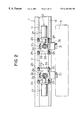
- FIG. 2 is a summarised front view of the overhead travelling carriage or the like that is used on the work transport system of the present invention.
- FIG. 3 is a summarised side view including a partial vertical section of the rail and overhead travelling carriage or the like for describing the mounting means of the rail on the work transport system of the present invention.
- FIG. 4 is a summarised perspective view of the rail and overhead travelling carriage or the like for describing the mounting means of the rail on the work transport system of the present invention.
- FIG. 5 is a summarised side view including a vertical section of the rail for describing the mounting means of the platform assembly on the rail on the work transport system of the present invention.
- FIG. 6 is a side view of a storage rack member and overhead travelling carriage for describing the mounting means of the storage rack member on the rail on the work transport system of the present invention.
- FIG. 7 is a complete side view of the storage rack member and overhead travelling carriage for describing the mounting means of the storage rack member on the rail on the work transport system of the present invention.
- FIG. 8 is a complete front view of the storage rack member and overhead travelling carriage for describing the mounting means of the storage rack member on the rail on the work transport system of the present invention.
- FIG. 9 is a partial plan view of the work transport system of the present invention.
- FIG. 10 is a summarised side view showing another embodiment of the work transport system of the present invention.
- FIG. 11 is a front view of the periphery of the platform assembly conveyor on the work transport system of FIG. 10 .
- FIG. 12 is a view showing the operation of the conveyor on the work transport system of FIG. 10 .
- FIG. 13 is a plan view showing a different embodiment of the conveyor on the work transport system of FIG. 10 .
- FIG. 14 is a front view showing the arrangement of the processing device and conveyor of the work transport system of FIG. 10 .
- FIG. 15 is a plan view showing the arrangement of the work transport system of FIG. 10 .
- FIG. 16 is an operation flow chart of the work transport system of FIG. 10 .
- FIG. 1 An overhead travelling carriage V that runs along a rail arranged near the ceiling that comprises the work transport system of the present invention will be described using FIG. 1 .
- the rail support member 8 is a rail support member and the rail support member 8 is formed from a vertical part 8 a , an upper horizontal part 8 b and a lower horizontal part 8 c .
- 9 is a bolt arranged with a screw on the upper and lower part and the upper parts of a pair of bolts 9 arranged at a predetermined spacing are embedded in the ceiling 10 so that the rail 1 is enclosed.
- 11 is a cover that covers the bolt 9 .
- the lower screw part of the bolt 9 is inserted in a hole arranged in the upper horizontal part 8 b of the rail support member 8 and the rail support member 8 is mounted on the ceiling 10 via the bolt 9 by the upper horizontal part 8 b of the rail support member 8 gripped by a pair of nuts 12 a , 12 b .
- 13 is a cap that covers the screw part of the bolt 9 and nut 12 b that project downwards from the upper horizontal part 8 b of the rail support member 8 .
- a pair of grooves 1 a are formed along the longitudinal direction of the rail 1 in the upper surface of the rail 1 and holes 8 d are arranged at predetermined spacing in the lower horizontal part 8 c of the rail support member 8 .
- a nut 14 is inserted in the grooves la formed in the rail 1
- a bolt 15 is inserted in the the hole 8 d arranged in the lower horizontal part 8 c of the rail support member 8 and the rail 1 is mounted on the rail support member 8 due to the screw of the bolt 15 being screwed into the nut 14 inserted in the groove 1 a formed in the rail 1 .
- the rail support member 8 is mounted on the ceiling 10 at a predetermined spacing via the bolt 9 as described above and the rail 1 is arranged near the ceiling 10 due to the mounting of the rail 1 an the rail support member 8 .
- a horizontal shaft 2 c is arranged in the main body 2 a of the carriage 2 via a bearing 2 b and a wheel 2 d that rotates along a lower horizontal surface 1 b of the rail 1 is mounted on one end of the horizontal shaft 2 c .
- a bevel gear 2 e is mounted on one end of the horizontal shaft 2 c and a bevel gear 2 g mounted on the output shaft of a motor 2 f engages with the bevel gear 2 e .
- Guide rollers 2 h are arranged so as to be able to freely rotate on the main body 2 a of the carriage 2 such that an upper vertical edge 1 c and lower vertical edge 1 d are each gripped.
- the wheel 2 d rotates and the carriage 2 is made to run along the rail 1 .
- the guide rollers 2 h grip each of the upper vertical edge 1 c and lower vertical edge 1 d of the rail 1 , the carriage 2 is able to run along the rail 1 in a stable state.
- a pivot shaft 2 i is mounted on the main body 2 a of the carriage 2 and the travelling carriage main body 3 is linked to that pivot shaft 2 i.
- the platform is a storage rack member 16 .
- 16 a is a framework and a pair of holes 16 b are arranged at a predetermined spacing in an upper horizontal part 16 a ′ of the framework 16 a .
- a nut 17 is inserted in the groove 1 a formed in the rail 1
- a bolt 18 is inserted in the the hole 16 b arranged in the upper horizontal part 16 a ′ of the framework 16 a and the framework 16 a is mounted on the upper surface of the rail 1 due to the screw of the bolt 18 being screwed into the nut 17 inserted in the groove 1 a formed in the rail 1 .
- the storage rack member 16 is comprised of a plurality of framework 16 a mounted on the rail 1 and the rack 16 c loaded on the lower horizontal part 16 a ′′ of the rack frame 16 a .
- a rack 16 c loaded on the lower horizontal part 16 a ′′ of the rack frame 16 a is positioned below the overhead travelling carriage V so that the work 4 loaded on the rack 16 c does not collide with the overhead travelling carriage V running along the rail 1 . Furthermore, the upper horizonal part 16 a ′ and lower horizonal part 16 a ′′ are of sufficient width so that the vertical part of the framework 16 a does not collide with the overhead travelling carriage V.
- the storage rack member 16 In order to reduce the transfer time of the work 4 by the overhead travelling carriage V to the rack 16 c and furthermore in order to increase the space below the rack 16 c , it is preferable for the storage rack member 16 to be as close to the rail 1 as possible in the vertical direction within a range so that the work 4 loaded on the rack 16 c does not collide with the overhead travelling carriage V.
- the rail 1 is arranged in the vicinity of the ceiling in this example as an approximate U-shape and the overhead travelling carriage V runs along the rail 1 .
- P 1 ,P 2 are processing stations for performing the desired processing on the work 4 and the storage rack member 16 is suspended from the rail 1 in the vicinity of the processing station P 1 .
- the work 4 transported by the overhead travelling carriage V to the processing station P 1 and loaded on the storage rack member 16 suspended from the rail 1 near the processing station P 1 without being loaded on the floor or the like.
- the work 4 is supplied to the processing station P 1 by the overhead travelling carriage V.
- Two storage rack members 16 are positioned in front of and behind the processing station P 2 .
- a predetermined amount of work 4 processed by the processing station P 2 as described above is loaded on the storage rack member 16 positioned to the right of processing station P 2 and processed work 4 or empty boxes into which work 4 may be stored are loaded in the storage rack member 16 positioned to the left of processing station P 2 .
- the storage rack member 16 is suspended below the rail 1 but the upper part of the bolt may be embedded in the ceiling, a plurality of rack frames 16 a may be mounted on the ceiling 10 and the racks 16 c may be mounted on the rack frame 16 a via the bolt by mounting the rack frame 16 a on the lower part of the bolt. Further, it is also possible to arrange the storage rack member 16 along the entire length of the rail 1 except the positions directly above the processing stations P 1 ,P 2 and not only in the vicinity of the processing stations P 1 ,P 2 .
- FIG. 10 shows the arrangement of the platform assembly a belt conveyor 42 inside a clean room.
- the belt conveyor 42 is suspended by framework 16 a , from the rail support member 8 above the rail 1 .
- 44 is a conveyor shaft and the belt conveyor 42 is able to store, for example, up to 5 pieces of work 4 .
- 46 is a controller which is connected to a host computer 52 via a communication cable.
- 48 is a motor connected to a contact wire.
- the controller 46 is operated by a command from the host computer 52 and the belt conveyor 42 is moved in the direction of the arrow shown in the drawing via the motor 48 by that signal.
- the right edge of the drawing of the belt conveyor 42 is a loading station 49 and the left edge is a delivery station 50 .
- 52 is the aforementioned host computer and controls the overhead travelling carriage V and belt conveyor 42 by communication. As shown in the operations of the belt conveyor 42 in FIG.
- the overhead travelling carriage V grips the work 4 and lowers it to the loading station 49 and unloads the work 4 on the belt conveyor 42 by implanting it on the belt conveyor 42 .
- the unloaded work 4 is transported towards the delivery station 50 by the belt conveyor 42 and transported from the delivery station 50 by the chuck device 5 .
- FIG. 13 shows an example of a circulation type conveyor 54 .
- the loading and delivery stations are arranged at positions 55 , 56 directly below the rail 1 and the work 4 unloaded at the station 55 is sent to the station 56 by the conveyor 54 and the work 4 unloaded at the station 56 is sent to the station 55 .
- conveyors 42 , 54 are belt conveyors but may be chain conveyors, slat conveyors or roller conveyors or the like.
- 60 is a work processing device such as a film production device, impurity injection device or cleaning device.
- 61 , 62 are those stations with, for example, the work 4 being received from the overhead travelling carriage V at the station 61 and processing being performed where after being transported to the processing device 60 and removing the case, the board or the like inside is taken out. Then, it is stored once again in the case inside the processing device 60 and transported from the station 62 . In this way, the stations 61 , 62 also double as buffers between the processes.
- the belt conveyor 42 is positioned along the rail 1 between the processing devices 60 , 60 as shown in the drawing for example, the belt conveyor 42 is used as a buffer between the left and right processing devices and after processing at the right processing device has finished, is used as a buffer before being moved to the left side processing device. If so arranged, the storage capacity of the stations 61 , 62 of the processing devices 60 may be reduced and the space of the clean room may be more effectively utilised.
- the conveyor 42 is positioned corresponding to the processing devices 60 as shown in FIG. 15 for example.
- the conveyor 42 a of FIG. 9 is used as a buffer for before the processing device 60 a and the conveyor 42 b is used as an exit side buffer of the processing device 60 a .
- a conveyor 42 c is used as a buffer for before the processing device 60 b and a conveyor 42 d is used as a buffer for between the processing devices 60 b , 60 c .
- These kinds of conveyors 42 are arranged as two types; as a ratio of 1:1 with the processing device (conveyors 42 a , 42 b , 42 c ) and a ratio of 1:2 with the processing device 60 (conveyor 42 d ).
- the controller 46 checks the amount of stored work 6 on the conveyor 42 and checks whether it will become full or not with the addition of a single unit. In either case, the work 4 is unloaded by the chuck device 5 to the loading station 49 which has been prevacated, a signal that confirms that the unloading of the work 4 has been completed is awaited and the counter of the existing amount in the controller 46 is increased by 1.
- a full signal is reported to the host computer 52 .
- the conveyor 42 is advanced by 1 unit of work 4 and the work 4 is moved 1 step at a time towards the delivery station 50 .
- a delivery command from the host computer 52 arrives, a check is carried out of whether the work 4 exists in the delivery station 50 or not and when it does not exist, the leading work 4 is advanced as far as the delivery station 50 .
- a signal showing that the chucking of the work 4 by the chuck device 5 has finished is awaited via the the host computer 52 .
- the conveyor 42 is advanced by one unit's worth of work and 1 is subtracted from the counter of the controller 46 showing the number of existing work.
- the present embodiment is able to effectively utilise the available space of a clean room and in particular, is able to effectively utilise the available space below the rail 1 .
- the belt conveyor 42 may be used as a buffer between the processing devices 60 , 60 , the time lag of the processes between processing devices 60 , 60 may be absorbed even if the scale of the stations 61 , 62 of the processing devices is small.
- the belt conveyor 42 is suspended by the framework 16 a on the rail 1 and the attachment and positioning of the belt conveyor 42 is simple. Also, as the belt conveyor 42 may stop the overhead travelling carriage V at the two points of the loading station 49 and delivery station 50 , the stoppage points are reduced.
- the number of stoppage marks arranged on the rail 1 may be reduced and the stoppage control is simplified. Furthermore, as the conveyor 42 transports first the previously received work 4 , the older the work, the more quickly it is sent to the next process. Furthermore, the controller 64 counts the existing amount of the work 4 at the conveyor 42 , always makes the loading station 49 vacant and thus if control so that each work 4 is continuously lined up, there is no need for control of each position of the work 4 on the conveyor 42 . Accordingly, the control of the conveyor 42 is also simplified.
- the present invention demonstrates the following advantages.
- the mounting operation of the storage rack member is simplified without the arrangement of a special mounting member on the ceiling.
- the framework As the framework is mounted on the rail by the screwing of a bolt into a nut which is inserted in a groove formed in the rail, the framework may be easily mounted and removed and the mounting position of the storage rack member may be easily changed along the rail.
- the vacant space under the rail may be used for the storage of work.
- the received work may be moved to a position other than the transfer station of the conveyor.
- a pair of transfer stations are arranged on the conveyor and the work received at one station is moved towards the other station by the conveyor. If this is arranged, the work first received is first transported and work is transported in the production order of the plant or storage order of the warehouse.
- the overhead travelling carriage system is arranged in a clean room, the valuable space inside the clean room may be effectively utilised. Furthermore, by arranging the conveyor corresponding to the work processing devices, the operation timing between processing devices may be absorbed by the conveyor. Yet further, if the conveyor is suspended by a rail, the arrangement of the conveyor is simplified.
Abstract
Description
Claims (7)
Applications Claiming Priority (4)
| Application Number | Priority Date | Filing Date | Title |
|---|---|---|---|
| JP8-278633 | 1996-09-30 | ||
| JP8278633A JP3067656B2 (en) | 1996-09-30 | 1996-09-30 | Work transfer system |
| JP9-082140 | 1997-03-13 | ||
| JP9082140A JP3067682B2 (en) | 1997-03-13 | 1997-03-13 | Overhead traveling vehicle system |
Publications (1)
| Publication Number | Publication Date |
|---|---|
| US6183184B1 true US6183184B1 (en) | 2001-02-06 |
Family
ID=26423155
Family Applications (1)
| Application Number | Title | Priority Date | Filing Date |
|---|---|---|---|
| US08/890,302 Expired - Lifetime US6183184B1 (en) | 1996-09-30 | 1997-07-09 | Work transport system |
Country Status (2)
| Country | Link |
|---|---|
| US (1) | US6183184B1 (en) |
| TW (1) | TW348162B (en) |
Cited By (45)
| Publication number | Priority date | Publication date | Assignee | Title |
|---|---|---|---|---|
| US6450318B1 (en) * | 2000-06-16 | 2002-09-17 | Tec Engineering Corporation | Overhead monorail system |
| US20030127410A1 (en) * | 2001-11-30 | 2003-07-10 | Murata Kikai Kabushiki Kaisha | Overhead travelling carriage |
| US20040047714A1 (en) * | 2002-09-06 | 2004-03-11 | Recif, Societe Anonyme | System for the conveying and storage of containers of semiconductor wafers, and transfer mechanism |
| US20040109746A1 (en) * | 2002-12-09 | 2004-06-10 | Murata Kikai Kabushiki Kaisha | Overhead travelling carriage system |
| US20040126208A1 (en) * | 2002-10-11 | 2004-07-01 | Brooks - Pri Automation, Inc. | Access to one or more levels of material storage shelves by an overhead hoist transport vehicle from a single track position |
| US20040191042A1 (en) * | 2003-03-31 | 2004-09-30 | Taiwan Semiconductor Manufacturing Co., Ltd. | Apparatus and method for positioning a cassette pod onto a loadport by an overhead hoist transport system |
| US20040265107A1 (en) * | 2003-03-04 | 2004-12-30 | Samsung Electronics Co., Ltd. | Stocker and transfer system including the same |
| US6851913B2 (en) | 2001-10-22 | 2005-02-08 | Daifuki Co., Ltd. | Transport system |
| US20050079041A1 (en) * | 2003-10-13 | 2005-04-14 | International Business Machines Corporation | Hoisting device for use with overhead traveling carriage system |
| EP1627834A1 (en) * | 2004-08-16 | 2006-02-22 | Murata Kikai Kabushiki Kaisha | Carrying system |
| US20060067809A1 (en) * | 2004-09-28 | 2006-03-30 | Murata Kikai Kabushiki Kaisha | Article storage facility and system for the same |
| US20060099054A1 (en) * | 2004-08-23 | 2006-05-11 | Friedman Gerald M | Elevator-based tool loading and buffering system |
| US20060104712A1 (en) * | 2004-08-24 | 2006-05-18 | Bufano Michael L | Transportation system |
| US20060182553A1 (en) * | 2005-01-20 | 2006-08-17 | Murata Kikai Kabushiki Kaisha | Carriage system |
| EP1707507A1 (en) * | 2005-03-31 | 2006-10-04 | Murata Kikai Kabushiki Kaisha | Overhead travelling vehicle system |
| US20070092359A1 (en) * | 2002-10-11 | 2007-04-26 | Brooks Automation, Inc. | Access to one or more levels of material storage shelves by an overhead hoist transport vehicle from a single track position |
| US20070110547A1 (en) * | 2002-06-19 | 2007-05-17 | Brooks Automation, Inc. | Automated material handling system for semiconductor manufacturing based on a combination of vertical carousels and overhead hoists |
| US20070128010A1 (en) * | 2005-12-06 | 2007-06-07 | International Business Machines Corporation | An apparatus for pod transportation within a semiconductor fabrication facility |
| US20070131167A1 (en) * | 2005-12-14 | 2007-06-14 | Tokyo Electron Limited | Substrate processing apparatus and lid supporting apparatus for the substrate processing apparatus |
| US20070264114A1 (en) * | 2006-05-09 | 2007-11-15 | Taiwan Semiconductor Manufacturing Co., Ltd. | High efficiency buffer stocker |
| US20080106414A1 (en) * | 2006-11-02 | 2008-05-08 | Murata Machinery, Ltd. | Overhead traveling vehicle having id reader |
| US20080156760A1 (en) * | 2006-12-28 | 2008-07-03 | Asyst Technologies Japan, Inc. | Storage apparatus for transported object |
| US20080168920A1 (en) * | 2007-01-12 | 2008-07-17 | Murata Machinery, Ltd. | Overhead traveling vehicle system and method of transporting processing equipment into, or out of position around the overhead traveling vehicle system |
| US20080221728A1 (en) * | 2007-03-07 | 2008-09-11 | Daifuku Co., Ltd. | Article Processing Facility and Its Control Method |
| US20090035102A1 (en) * | 2007-07-31 | 2009-02-05 | Olaf Zimmerhackl | Method and system for locally buffering substrate carriers in an overhead transport system for enhancing input/output capabilities of process tools |
| US20090120320A1 (en) * | 2007-11-13 | 2009-05-14 | Murata Machinery, Ltd. | Overhead traveling vehicle system and construction method of buffer in the system |
| US20110056900A1 (en) * | 2008-04-09 | 2011-03-10 | Daifuku Co., Ltd. | Article Transport Facility |
| US20120080396A1 (en) * | 2010-10-04 | 2012-04-05 | Daifuku Co., Ltd. | Article Transport Device |
| EP2450296A1 (en) * | 2010-11-04 | 2012-05-09 | Muratec Automation Co., Ltd. | System and method for transporting an article between processing devices |
| US20130019772A1 (en) * | 2010-04-02 | 2013-01-24 | Eiji Wada | Side buffer for a transport vehicle that travels along the ceiling, and transport vehicle system |
| US20130259617A1 (en) * | 2012-03-27 | 2013-10-03 | Ming Wang | Overhead cartridge placement system |
| US20130264301A1 (en) * | 2012-04-05 | 2013-10-10 | Samsung Electronics Co., Ltd. | Hoist apparatus |
| TWI462862B (en) * | 2010-03-08 | 2014-12-01 | Daifuku Kk | Article transport facility |
| US9187260B2 (en) | 2010-11-04 | 2015-11-17 | Murata Machinery, Ltd. | Conveying system and conveying method |
| CN105312276A (en) * | 2015-11-20 | 2016-02-10 | 苏州赛森电子科技有限公司 | Ultrasonic treatment equipment during double-diffusion metal-oxide-semiconductor (DMOS) wafer processing |
| CN105668175A (en) * | 2016-04-21 | 2016-06-15 | 广州东焊焊接设备有限公司 | Suspension transferring loader |
| EP3192753A1 (en) * | 2012-05-11 | 2017-07-19 | Ocado Innovation Limited | Storage systems and methods for retrieving units from a storage system |
| CN107380910A (en) * | 2017-07-21 | 2017-11-24 | 艾信智慧医疗科技发展(苏州)有限公司 | Hoisting bracket for hospital's logistics system |
| US9896283B2 (en) * | 2015-11-17 | 2018-02-20 | Daifuku Co., Ltd. | Article transport facility |
| CN108584270A (en) * | 2018-07-24 | 2018-09-28 | 深圳市鲸仓科技有限公司 | The track exchanging device of stereo warehouse |
| US10418263B2 (en) | 2018-01-20 | 2019-09-17 | Boris Kesil | Overhead transportation system for transporting objects between multiple work stations |
| CN111886190A (en) * | 2018-03-22 | 2020-11-03 | 村田机械株式会社 | Stocker system |
| CN112533844A (en) * | 2018-07-24 | 2021-03-19 | 深圳市鲸仓科技有限公司 | Three-dimensional warehousing system |
| US20220135464A1 (en) * | 2020-11-02 | 2022-05-05 | Samsung Display Co., Ltd. | Load carrier and window manufacturing system having the same |
| US11478825B2 (en) | 2007-01-12 | 2022-10-25 | Opex Corporation | Material handling apparatus for delivering or retrieving items |
Citations (7)
| Publication number | Priority date | Publication date | Assignee | Title |
|---|---|---|---|---|
| US840807A (en) * | 1906-01-19 | 1907-01-08 | Alliance Machine Co | Take-up device for crane lifts or hoists. |
| US3593869A (en) * | 1969-03-06 | 1971-07-20 | Ppg Industries Inc | Crane apparatus with hoist means located between spaced platforms |
| US4049132A (en) * | 1975-09-12 | 1977-09-20 | Salen & Wicander Terminalsystem Ab | Crane adapted to the handling of uniform cargo units |
| US4474523A (en) * | 1981-01-05 | 1984-10-02 | Norsk Hydro A.S. | Unloading means for bulk material |
| DE3342849A1 (en) * | 1983-11-26 | 1985-06-13 | Erwin Mehne GmbH & Co, 7100 Heilbronn | Container transport system |
| US4735539A (en) * | 1986-04-28 | 1988-04-05 | Oy Tampella Ab | Apparatus for handling sheets or the like |
| US4787804A (en) * | 1985-09-16 | 1988-11-29 | Aktiebolaget Knight Konsulterande Ingenjorer | Material handling system |
-
1997
- 1997-06-03 TW TW086107624A patent/TW348162B/en not_active IP Right Cessation
- 1997-07-09 US US08/890,302 patent/US6183184B1/en not_active Expired - Lifetime
Patent Citations (7)
| Publication number | Priority date | Publication date | Assignee | Title |
|---|---|---|---|---|
| US840807A (en) * | 1906-01-19 | 1907-01-08 | Alliance Machine Co | Take-up device for crane lifts or hoists. |
| US3593869A (en) * | 1969-03-06 | 1971-07-20 | Ppg Industries Inc | Crane apparatus with hoist means located between spaced platforms |
| US4049132A (en) * | 1975-09-12 | 1977-09-20 | Salen & Wicander Terminalsystem Ab | Crane adapted to the handling of uniform cargo units |
| US4474523A (en) * | 1981-01-05 | 1984-10-02 | Norsk Hydro A.S. | Unloading means for bulk material |
| DE3342849A1 (en) * | 1983-11-26 | 1985-06-13 | Erwin Mehne GmbH & Co, 7100 Heilbronn | Container transport system |
| US4787804A (en) * | 1985-09-16 | 1988-11-29 | Aktiebolaget Knight Konsulterande Ingenjorer | Material handling system |
| US4735539A (en) * | 1986-04-28 | 1988-04-05 | Oy Tampella Ab | Apparatus for handling sheets or the like |
Cited By (100)
| Publication number | Priority date | Publication date | Assignee | Title |
|---|---|---|---|---|
| US6450318B1 (en) * | 2000-06-16 | 2002-09-17 | Tec Engineering Corporation | Overhead monorail system |
| US6851913B2 (en) | 2001-10-22 | 2005-02-08 | Daifuki Co., Ltd. | Transport system |
| US20030127410A1 (en) * | 2001-11-30 | 2003-07-10 | Murata Kikai Kabushiki Kaisha | Overhead travelling carriage |
| US7611023B2 (en) * | 2001-11-30 | 2009-11-03 | Murata Kikai Kabushiki Kaisha | Overhead travelling carriage |
| US20150303089A1 (en) * | 2002-06-19 | 2015-10-22 | Murata Machinery Ltd. | Automated material handling system for semiconductor manufacturing based on a combination of vertical carousels and overhead hoists |
| US20150303087A1 (en) * | 2002-06-19 | 2015-10-22 | Murata Machinery Ltd. | Automated material handling system for semiconductor manufacturing based on a combination of vertical carousels and overhead hoists |
| US9881823B2 (en) * | 2002-06-19 | 2018-01-30 | Murata Machinery Ltd. | Automated material handling system for semiconductor manufacturing based on a combination of vertical carousels and overhead hoists |
| US10141212B2 (en) | 2002-06-19 | 2018-11-27 | Murata Machinery Ltd. | Automated material handling system for semiconductor manufacturing based on a combination of vertical carousels and overhead hoists |
| US10147627B2 (en) | 2002-06-19 | 2018-12-04 | Murata Machinery Ltd. | Automated material handling system for semiconductor manufacturing based on a combination of vertical carousels and overhead hoists |
| US10381251B2 (en) | 2002-06-19 | 2019-08-13 | Murata Machinery Ltd. | Automated material handling system for semiconductor manufacturing based on a combination of vertical carousels and overhead hoists |
| US9620397B2 (en) | 2002-06-19 | 2017-04-11 | Murata Machinery Ltd. | Automated material handling system for semiconductor manufacturing based on a combination of vertical carousels and overhead hoists |
| US20070110547A1 (en) * | 2002-06-19 | 2007-05-17 | Brooks Automation, Inc. | Automated material handling system for semiconductor manufacturing based on a combination of vertical carousels and overhead hoists |
| US8197172B2 (en) | 2002-06-19 | 2012-06-12 | Murata Machinery, Ltd. | Automated material handling system for semiconductor manufacturing based on a combination of vertical carousels and overhead hoists |
| US20100174405A1 (en) * | 2002-06-19 | 2010-07-08 | Murata Machinery, Ltd. | Automated Material Handling System for Semiconductor Manufacturing Based on a Combination of Vertical Carousels and Overhead Hoists |
| US7771153B2 (en) | 2002-06-19 | 2010-08-10 | Murata Machinery Ltd. | Automated material handling system for semiconductor manufacturing based on a combination of vertical carousels and overhead hoists |
| US20040047714A1 (en) * | 2002-09-06 | 2004-03-11 | Recif, Societe Anonyme | System for the conveying and storage of containers of semiconductor wafers, and transfer mechanism |
| US10957569B2 (en) | 2002-10-11 | 2021-03-23 | Murata Machinery Ltd. | Access to one or more levels of material storage shelves by an overhead hoist transport vehicle from a single track position |
| KR100880291B1 (en) * | 2002-10-11 | 2009-01-23 | 브룩스 오토메이션, 인크. | Access to one or more levels of material storage shelves by an overhead hoist transport vehicle from a single track position |
| CN1849251B (en) * | 2002-10-11 | 2012-04-18 | 村田机械株式会社 | Access to one or more levels of material storage shelves by an overhead hoist transport vehicle from a single track position |
| US20070092359A1 (en) * | 2002-10-11 | 2007-04-26 | Brooks Automation, Inc. | Access to one or more levels of material storage shelves by an overhead hoist transport vehicle from a single track position |
| WO2004034438A3 (en) * | 2002-10-11 | 2005-10-06 | Brooks Automation Inc | Access to one or more levels of material storage shelves by an overhead hoist transport vehicle from a single track position |
| US20040126208A1 (en) * | 2002-10-11 | 2004-07-01 | Brooks - Pri Automation, Inc. | Access to one or more levels of material storage shelves by an overhead hoist transport vehicle from a single track position |
| US20040109746A1 (en) * | 2002-12-09 | 2004-06-10 | Murata Kikai Kabushiki Kaisha | Overhead travelling carriage system |
| US20040265107A1 (en) * | 2003-03-04 | 2004-12-30 | Samsung Electronics Co., Ltd. | Stocker and transfer system including the same |
| US20040191042A1 (en) * | 2003-03-31 | 2004-09-30 | Taiwan Semiconductor Manufacturing Co., Ltd. | Apparatus and method for positioning a cassette pod onto a loadport by an overhead hoist transport system |
| US6848882B2 (en) * | 2003-03-31 | 2005-02-01 | Taiwan Semiconductor Manufacturing Co., Ltd | Apparatus and method for positioning a cassette pod onto a loadport by an overhead hoist transport system |
| US20050079041A1 (en) * | 2003-10-13 | 2005-04-14 | International Business Machines Corporation | Hoisting device for use with overhead traveling carriage system |
| US20060051192A1 (en) * | 2004-08-16 | 2006-03-09 | Murata Kikai Kabushiki Kaisha | Carrying system |
| EP1627834A1 (en) * | 2004-08-16 | 2006-02-22 | Murata Kikai Kabushiki Kaisha | Carrying system |
| US9368382B2 (en) | 2004-08-23 | 2016-06-14 | Brooks Automation, Inc. | Elevator-based tool loading and buffering system |
| US20100158643A1 (en) * | 2004-08-23 | 2010-06-24 | Brooks Automation, Inc. | Elevator-based tool loading and buffering system |
| US20110142575A1 (en) * | 2004-08-23 | 2011-06-16 | Brooks Automation, Inc. | Elevator-based tool loading and buffering system |
| US7806643B2 (en) | 2004-08-23 | 2010-10-05 | Brooks Automation, Inc. | Elevator-based tool loading and buffering system |
| US8678734B2 (en) | 2004-08-23 | 2014-03-25 | Brooks Automation, Inc. | Elevator-based tool loading and buffering system |
| US20060099054A1 (en) * | 2004-08-23 | 2006-05-11 | Friedman Gerald M | Elevator-based tool loading and buffering system |
| US20060104712A1 (en) * | 2004-08-24 | 2006-05-18 | Bufano Michael L | Transportation system |
| US20100147181A1 (en) * | 2004-08-24 | 2010-06-17 | Brooks Automation, Inc. | Elevator-based tool loading and buffering system |
| US7413396B2 (en) * | 2004-09-28 | 2008-08-19 | Murata Kikai Kabushiki Kaisha | Article storage facility and system for the same |
| US20060067809A1 (en) * | 2004-09-28 | 2006-03-30 | Murata Kikai Kabushiki Kaisha | Article storage facility and system for the same |
| US20060182553A1 (en) * | 2005-01-20 | 2006-08-17 | Murata Kikai Kabushiki Kaisha | Carriage system |
| US7891929B2 (en) * | 2005-01-20 | 2011-02-22 | Murata Kikai Kabushiki Kaisha | Carriage system |
| EP1707507A1 (en) * | 2005-03-31 | 2006-10-04 | Murata Kikai Kabushiki Kaisha | Overhead travelling vehicle system |
| US20060222479A1 (en) * | 2005-03-31 | 2006-10-05 | Murata Kikai Kabushiki Kaisha | Overhead traveling vehicle system |
| US7972104B2 (en) * | 2005-03-31 | 2011-07-05 | Murata Kikai Kabushiki Kaisha | Overhead traveling vehicle system |
| US20070128010A1 (en) * | 2005-12-06 | 2007-06-07 | International Business Machines Corporation | An apparatus for pod transportation within a semiconductor fabrication facility |
| US7883579B2 (en) * | 2005-12-14 | 2011-02-08 | Tokyo Electron Limited | Substrate processing apparatus and lid supporting apparatus for the substrate processing apparatus |
| US20070131167A1 (en) * | 2005-12-14 | 2007-06-14 | Tokyo Electron Limited | Substrate processing apparatus and lid supporting apparatus for the substrate processing apparatus |
| US9659801B2 (en) | 2006-05-09 | 2017-05-23 | Taiwan Semiconductor Manufacturing Co., Ltd. | High efficiency buffer stocker |
| US20070264114A1 (en) * | 2006-05-09 | 2007-11-15 | Taiwan Semiconductor Manufacturing Co., Ltd. | High efficiency buffer stocker |
| US8308418B2 (en) * | 2006-05-09 | 2012-11-13 | Taiwan Semiconductor Manufacturing Co., Ltd. | High efficiency buffer stocker |
| US7796049B2 (en) * | 2006-11-02 | 2010-09-14 | Murata Machinery, Ltd. | Overhead traveling vehicle having ID reader |
| US20080106414A1 (en) * | 2006-11-02 | 2008-05-08 | Murata Machinery, Ltd. | Overhead traveling vehicle having id reader |
| US20080156760A1 (en) * | 2006-12-28 | 2008-07-03 | Asyst Technologies Japan, Inc. | Storage apparatus for transported object |
| US7762754B2 (en) * | 2006-12-28 | 2010-07-27 | Muratec Automation Co., Ltd. | Storage apparatus for transported object |
| CN101209774B (en) * | 2006-12-28 | 2012-09-19 | 村田自动化机械有限公司 | Storage apparatus for transported object |
| US11491513B1 (en) | 2007-01-12 | 2022-11-08 | Opex Corporation | Material handling apparatus for delivering or retrieving items |
| US11478825B2 (en) | 2007-01-12 | 2022-10-25 | Opex Corporation | Material handling apparatus for delivering or retrieving items |
| US11565283B1 (en) | 2007-01-12 | 2023-01-31 | Opex Corporation | Material handling apparatus for delivering or retrieving items |
| US11938517B2 (en) | 2007-01-12 | 2024-03-26 | Opex Corporation | Material handling apparatus for delivering or retrieving items |
| US20080168920A1 (en) * | 2007-01-12 | 2008-07-17 | Murata Machinery, Ltd. | Overhead traveling vehicle system and method of transporting processing equipment into, or out of position around the overhead traveling vehicle system |
| US7735424B2 (en) * | 2007-01-12 | 2010-06-15 | Murata Machinery, Ltd. | Overhead traveling vehicle system and method of transporting processing equipment into, or out of position around the overhead traveling vehicle system |
| US8374719B2 (en) * | 2007-03-07 | 2013-02-12 | Daifuku Co., Ltd. | Article processing facility and its control method |
| NL2001351C2 (en) * | 2007-03-07 | 2014-03-04 | Daifuku Kk | ARTICLE PROCESSING INSTALLATION AND ITS CONTROL METHOD. |
| US20080221728A1 (en) * | 2007-03-07 | 2008-09-11 | Daifuku Co., Ltd. | Article Processing Facility and Its Control Method |
| US8047762B2 (en) * | 2007-07-31 | 2011-11-01 | Globalfoundries Inc. | Method and system for locally buffering substrate carriers in an overhead transport system for enhancing input/output capabilities of process tools |
| US20090035102A1 (en) * | 2007-07-31 | 2009-02-05 | Olaf Zimmerhackl | Method and system for locally buffering substrate carriers in an overhead transport system for enhancing input/output capabilities of process tools |
| US20090120320A1 (en) * | 2007-11-13 | 2009-05-14 | Murata Machinery, Ltd. | Overhead traveling vehicle system and construction method of buffer in the system |
| US7789019B2 (en) | 2007-11-13 | 2010-09-07 | Murata Machinery, Ltd. | Overhead traveling vehicle system and construction method of buffer in the system |
| US9011068B2 (en) * | 2008-04-09 | 2015-04-21 | Daifuku Co., Ltd. | Article transport facility |
| US20110056900A1 (en) * | 2008-04-09 | 2011-03-10 | Daifuku Co., Ltd. | Article Transport Facility |
| TWI462862B (en) * | 2010-03-08 | 2014-12-01 | Daifuku Kk | Article transport facility |
| US8550006B2 (en) * | 2010-04-02 | 2013-10-08 | Murata Machinery, Ltd. | Side buffer for a transport vehicle that travels along the ceiling, and transport vehicle system |
| US20130019772A1 (en) * | 2010-04-02 | 2013-01-24 | Eiji Wada | Side buffer for a transport vehicle that travels along the ceiling, and transport vehicle system |
| US8757401B2 (en) * | 2010-10-04 | 2014-06-24 | Daifuku Co., Ltd. | Article transport device |
| US20120080396A1 (en) * | 2010-10-04 | 2012-04-05 | Daifuku Co., Ltd. | Article Transport Device |
| EP2548822A1 (en) * | 2010-11-04 | 2013-01-23 | Muratec Automation Co., Ltd. | System and method for transporting an article between processing devices |
| CN102530553A (en) * | 2010-11-04 | 2012-07-04 | 村田自动化机械有限公司 | Transport system and transport method |
| EP2450296A1 (en) * | 2010-11-04 | 2012-05-09 | Muratec Automation Co., Ltd. | System and method for transporting an article between processing devices |
| US9187260B2 (en) | 2010-11-04 | 2015-11-17 | Murata Machinery, Ltd. | Conveying system and conveying method |
| US9263311B2 (en) | 2010-11-04 | 2016-02-16 | Murata Machinery, Ltd. | Transport system and transport method |
| CN102530553B (en) * | 2010-11-04 | 2016-06-29 | 村田机械株式会社 | Conveyer and transport method |
| US20130259617A1 (en) * | 2012-03-27 | 2013-10-03 | Ming Wang | Overhead cartridge placement system |
| US20130264301A1 (en) * | 2012-04-05 | 2013-10-10 | Samsung Electronics Co., Ltd. | Hoist apparatus |
| EP3192753A1 (en) * | 2012-05-11 | 2017-07-19 | Ocado Innovation Limited | Storage systems and methods for retrieving units from a storage system |
| US9896283B2 (en) * | 2015-11-17 | 2018-02-20 | Daifuku Co., Ltd. | Article transport facility |
| CN105312276A (en) * | 2015-11-20 | 2016-02-10 | 苏州赛森电子科技有限公司 | Ultrasonic treatment equipment during double-diffusion metal-oxide-semiconductor (DMOS) wafer processing |
| CN105668175A (en) * | 2016-04-21 | 2016-06-15 | 广州东焊焊接设备有限公司 | Suspension transferring loader |
| CN105668175B (en) * | 2016-04-21 | 2018-01-02 | 广州东焊焊接设备有限公司 | Rotary trailing transferring loader |
| CN107380910A (en) * | 2017-07-21 | 2017-11-24 | 艾信智慧医疗科技发展(苏州)有限公司 | Hoisting bracket for hospital's logistics system |
| US10418263B2 (en) | 2018-01-20 | 2019-09-17 | Boris Kesil | Overhead transportation system for transporting objects between multiple work stations |
| US11239102B2 (en) * | 2018-03-22 | 2022-02-01 | Murata Machinery, Ltd. | Stocker system |
| CN111886190B (en) * | 2018-03-22 | 2022-06-28 | 村田机械株式会社 | Stocker system |
| CN111886190A (en) * | 2018-03-22 | 2020-11-03 | 村田机械株式会社 | Stocker system |
| TWI814792B (en) * | 2018-03-22 | 2023-09-11 | 日商村田機械股份有限公司 | Warehousing system |
| EP3812309A4 (en) * | 2018-07-24 | 2021-08-18 | Shenzhen Whalehouse Technology Company Limited | Three-dimensional warehousing system |
| CN112533844A (en) * | 2018-07-24 | 2021-03-19 | 深圳市鲸仓科技有限公司 | Three-dimensional warehousing system |
| US11745944B2 (en) | 2018-07-24 | 2023-09-05 | Shenzhen Whalehouse Technology Company Limited | Three-dimensional warehouse system |
| CN108584270A (en) * | 2018-07-24 | 2018-09-28 | 深圳市鲸仓科技有限公司 | The track exchanging device of stereo warehouse |
| US20220135464A1 (en) * | 2020-11-02 | 2022-05-05 | Samsung Display Co., Ltd. | Load carrier and window manufacturing system having the same |
| US11878931B2 (en) * | 2020-11-02 | 2024-01-23 | Samsung Display Co., Ltd. | Load carrier and window manufacturing system having the same |
Also Published As
| Publication number | Publication date |
|---|---|
| TW348162B (en) | 1998-12-21 |
Similar Documents
| Publication | Publication Date | Title |
|---|---|---|
| US6183184B1 (en) | Work transport system | |
| US11230447B2 (en) | Storage and retrieval system transport vehicle | |
| US9073691B2 (en) | Article transport facility | |
| US7128521B2 (en) | Method of manipulating storage units | |
| KR960005533B1 (en) | Load transport system for automated warehousing | |
| EP1626012B1 (en) | Overhead travelling carriage system | |
| JP2529687Y2 (en) | Sorting device with goods transport means that can be pre-positioned with respect to the unloading destination | |
| CA2406812C (en) | Versaroll overhead conveyor system | |
| US20040101386A1 (en) | Vertical carousel with top and side access stations | |
| JP3067682B2 (en) | Overhead traveling vehicle system | |
| US20080217268A1 (en) | Frame system for an article storage apparatus | |
| US10035652B2 (en) | Storage system having a transport system formed by magnetically driven shuttles | |
| JP2004131258A (en) | Automatic warehouse | |
| IE20070816A1 (en) | Frame system for an article storage apparatus | |
| CN110329699A (en) | A kind of conveying device for the automatic balance piler of workpiece | |
| CN112573051B (en) | Article conveying device | |
| CN111977239A (en) | Operation system and control method of box type composite elevator | |
| JP4583554B2 (en) | Container buffer and supply device and container buffer and supply method | |
| JPH042485B2 (en) | ||
| EP4265542A1 (en) | Storage system, truck for storage system and rack construction | |
| EP0853558B1 (en) | Storage system for objects arranged at a distance from one another | |
| EP3653545A1 (en) | A conveyor junction | |
| JP2000118605A (en) | Warehouse system | |
| JPH04891B2 (en) | ||
| JP3182779B2 (en) | Pallet processing equipment |
Legal Events
| Date | Code | Title | Description |
|---|---|---|---|
| AS | Assignment |
Owner name: MURATA MACHINERY, LTD., JAPAN Free format text: ASSIGNMENT OF ASSIGNORS INTEREST;ASSIGNOR:SHIWAKU, TAMOTSU;REEL/FRAME:008727/0198 Effective date: 19970530 |
|
| STCF | Information on status: patent grant |
Free format text: PATENTED CASE |
|
| FPAY | Fee payment |
Year of fee payment: 4 |
|
| FEPP | Fee payment procedure |
Free format text: PAYOR NUMBER ASSIGNED (ORIGINAL EVENT CODE: ASPN); ENTITY STATUS OF PATENT OWNER: LARGE ENTITY |
|
| FPAY | Fee payment |
Year of fee payment: 8 |
|
| FPAY | Fee payment |
Year of fee payment: 12 |
|
| IPR | Aia trial proceeding filed before the patent and appeal board: inter partes review |
Free format text: TRIAL NO: IPR2015-01539 Opponent name: DAIFUKU CO., LTD. ANDDAIFUKU AMERICA CORP. Effective date: 20150702 |
|
| IPR | Aia trial proceeding filed before the patent and appeal board: inter partes review |
Free format text: TRIAL NO: IPR2015-01541 Opponent name: DAIFUKU CO., LTD. ANDDAIFUKU AMERICA CORP. Effective date: 20150702 |