US6176594B1 - Streamlined fluorescent lamp ballast and mounting assembly - Google Patents
Streamlined fluorescent lamp ballast and mounting assembly Download PDFInfo
- Publication number
- US6176594B1 US6176594B1 US09/094,060 US9406098A US6176594B1 US 6176594 B1 US6176594 B1 US 6176594B1 US 9406098 A US9406098 A US 9406098A US 6176594 B1 US6176594 B1 US 6176594B1
- Authority
- US
- United States
- Prior art keywords
- ballast
- compact
- socket
- lamp
- mounting plate
- Prior art date
- Legal status (The legal status is an assumption and is not a legal conclusion. Google has not performed a legal analysis and makes no representation as to the accuracy of the status listed.)
- Expired - Fee Related
Links
Images


Classifications
-
- F—MECHANICAL ENGINEERING; LIGHTING; HEATING; WEAPONS; BLASTING
- F21—LIGHTING
- F21V—FUNCTIONAL FEATURES OR DETAILS OF LIGHTING DEVICES OR SYSTEMS THEREOF; STRUCTURAL COMBINATIONS OF LIGHTING DEVICES WITH OTHER ARTICLES, NOT OTHERWISE PROVIDED FOR
- F21V23/00—Arrangement of electric circuit elements in or on lighting devices
- F21V23/02—Arrangement of electric circuit elements in or on lighting devices the elements being transformers, impedances or power supply units, e.g. a transformer with a rectifier
-
- F—MECHANICAL ENGINEERING; LIGHTING; HEATING; WEAPONS; BLASTING
- F21—LIGHTING
- F21V—FUNCTIONAL FEATURES OR DETAILS OF LIGHTING DEVICES OR SYSTEMS THEREOF; STRUCTURAL COMBINATIONS OF LIGHTING DEVICES WITH OTHER ARTICLES, NOT OTHERWISE PROVIDED FOR
- F21V19/00—Fastening of light sources or lamp holders
- F21V19/0075—Fastening of light sources or lamp holders of tubular light sources, e.g. ring-shaped fluorescent light sources
- F21V19/0095—Fastening of light sources or lamp holders of tubular light sources, e.g. ring-shaped fluorescent light sources of U-shaped tubular light sources, e.g. compact fluorescent tubes
-
- F—MECHANICAL ENGINEERING; LIGHTING; HEATING; WEAPONS; BLASTING
- F21—LIGHTING
- F21V—FUNCTIONAL FEATURES OR DETAILS OF LIGHTING DEVICES OR SYSTEMS THEREOF; STRUCTURAL COMBINATIONS OF LIGHTING DEVICES WITH OTHER ARTICLES, NOT OTHERWISE PROVIDED FOR
- F21V21/00—Supporting, suspending, or attaching arrangements for lighting devices; Hand grips
- F21V21/02—Wall, ceiling, or floor bases; Fixing pendants or arms to the bases
-
- F—MECHANICAL ENGINEERING; LIGHTING; HEATING; WEAPONS; BLASTING
- F21—LIGHTING
- F21Y—INDEXING SCHEME ASSOCIATED WITH SUBCLASSES F21K, F21L, F21S and F21V, RELATING TO THE FORM OR THE KIND OF THE LIGHT SOURCES OR OF THE COLOUR OF THE LIGHT EMITTED
- F21Y2103/00—Elongate light sources, e.g. fluorescent tubes
- F21Y2103/30—Elongate light sources, e.g. fluorescent tubes curved
- F21Y2103/37—U-shaped
Definitions
- the present invention relates generally to fluorescent lighting. More specifically, the invention relates to a streamlined mounting assembly for securing a fluorescent lighting ballast and socket to any standard junction box.
- ADA Americans with Disabilities Act
- Fluorescent lighting is a preferred means of lighting in heavily trafficked areas where bright, uniform, and efficient illumination is desired, chiefly because fluorescent lighting provides the safest, most economical form of lighting available while providing relatively uniform illumination, all without significant heat.
- the present invention provides a safe, cost efficient means for providing fashionable fluorescent lighting, keeping all of the above referenced concerns in mind. More particularly, the mounting system and ballast disclosed in the present invention avoids the costly complications associated with the re-engineering, of current lighting systems, or the added expenses of reconstructing walls to include special junction boxes capable of accommodating fluorescent lights conforming with the strict requirements of the ADA.
- the above and other objects are achieved by the present invention, which includes a fluorescent light mounting assembly, having a lamp ballast, a socket for the bulb and a ballast mounting plate which secures the lamp ballast and socket to the electrical junction box.
- the ballast mounting plate includes a bottom flat plate and two upwardly extending side flanges, the side flanges being parallel to one another on the outside surface of the bottom plate i.e., the side facing away from the electrical junction box.
- the flanges can be provided with inwardly directed locking edges.
- the side flanges and the bottom flat plate form a channel dimensioned to securely receive the base of a lamp socket and lamp ballast assembly.
- the lamp ballast has a first length and the ballast mounting plate has a second length, the second length being greater than the first length so as to form a socket mounting area on the ballast mounting plate adjacent the lamp ballast.
- the socket mounting area is provided beneath the lamp ballast so that when the base of the lamp ballast and socket assembly is mounted on the socket mounting area, the fluorescent bulbs is secured in the socket extends above the lamp ballast, projecting beyond the length of the lamp ballast.
- the present invention also includes a fluorescent lamp wall sconce, having an interior surface, the housing being capable of at least partially transmitting light therethrough and securable to a wall.
- the sconce fixture is provided with a housing. Disposed inside the housing is a lamp ballast.
- a ballast mounting plate is fixed to the lamp ballast.
- the ballast mounting plate includes a bottom plate and two side flanges, the side flanges being disposed parallel to one another on one side of the bottom plate. The side flanges and the bottom plate form a channel dimensioned to securely receive a base of a lamp socket and the lamp ballast.
- the lamp ballast has a first length
- the ballast mounting plate has a second length, the second length being greater than the first length so as to form a socket mounting area on the ballast mounting plate adjacent the lamp ballast.
- the socket mounting area is provided behind the lamp ballast so that when the base of the lamp socket is mounted on the socket mounting area, fluorescent bulbs secured in the socket extend above the lamp ballast along the length of the lamp ballast.
- the housing includes one or more apertures to allow the ballast mounting plate to be secured to a standard, electrical junction box disposed in the wall, so that the ballast mounting plate is flush with the wall.
- the invention further includes a method of mounting a fluorescent lamp ballast.
- a junction box is provided inside a wall so that the upper rim or edge of the junction box is flush with the plane of the wall.
- a ballast mounting plate having a bottom plate and side flanges which form a channel for receiving a base of a fluorescent lamp socket and a lamp ballast, is provided. The lamp ballast and the lamp socket are inserted into the channel, and the ballast mounting plate is secured to the junction box.
- FIG. 1 is a top, perspective and exploded view of a light fixture conforming to the standards of the Americans With Disabilities Act (“ADA”) with the ballast mounting plate, P.L. ballast, socket, bulb and dispersing shield according to the present invention;
- ADA Americans With Disabilities Act
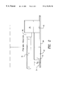
- FIG. 2 is a side view of a P.L. ballast/socket assembly showing the P.L. lamp in place and further illustrating the device of the present invention with the ballast container secured to a mounting plate for an electrical junction box;
- FIG. 3A is a top plan view of the preferred mounting plate or bracket which forms a part of the present invention.
- FIG. 3B is a top plan view of an alternate mounting plate or bracket which forms a part of the present invention.
- FIG. 4 is a cross-sectional view of the mounting plate, taken along lines 4 — 4 of FIG. 3A also showing the ballast container (the socket assembly with the fluorescent bulb being not shown for clarity of illustration); and the inter-engagement of the upwardly extending legs of the mounting plate or bracket with a pair of notches in the sidewalls of the ballast container, consistent with the invention.
- an ADA-compliant lighting fixture 10 is adapted to be selectively secured and connected to a standard (pre-existing or new installation) electrical junction box 20 while being enclosed by a light-dispensing shield or wall sconce 16 (shown in section).
- the electrical junction box 20 is secured to a wood cross beam (not shown) in a conventional manner and is recessed into a wall so that its top edge 21 is flush with the sheetrock of the wall.
- These electrical junction boxes are quite conventional and, yet, the junction box illustrated in the preferred embodiment of the present invention is an octagon with upwardly extending walls 22 forming the sides.
- An electrical cable enters one of the sides 22 (or the rear) of the electrical junction box through a knock-out hole, in a conventional manner, to supply electrical power to the electrical ballast container of the present invention.
- a pair of inwardly extending ears or lugs 26 (coplanar with the top edge 21 ), on opposed sides 22 of the electrical junction box, provide threaded apertures 28 . These apertures are adapted to receive a screw 30 which first passes through an arcuate-shaped slot 32 of a mounting plate or bracket 34 and then into the aperture 28 of the lug 26 of the electrical junction box 20 .
- the ballast in its simplest configuration, consists of a thin profile parallel pipe which is provided on two of its opposite sides with longitudinal notches 42 which receive upwardly and inwardly extending tabs or flanges 50 of the mounting plate 40 (see FIG. 4 ).
- the top of the ballast container is provided, on one of its ends, with an upwardly projecting socket mechanism in a convention manner which serves to selectively receive electrical connection of the P.L.-shaped fluorescent bulb.
- Ballast container 40 may be fixedly attached to ballast mounting plate or bracket 34 and is positioned underneath the fluorescent bulbs 18 (two sockets can be provided, for two bulbs) thus eliminating the uneven lighting or casting of shadows which occurs when the ballast is orientated in its conventional adjacent configuration.
- Support housing 35 provides means for both supporting socket 36 and for encasing the wires supplying electricity to socket 36 from ballast 30 .
- the preferred mounting plate or bracket 34 is best shown in FIG. 3 A and is formed from flat sheet metal. It comprises a flat rectangular central portion 60 and a pair of opposed semi-circular regions 51 . A pair of inner, arcuate cut-outs 37 are provided to regions 51 as well as a pair of opposed, larger diameter arcuate cut-out segments 32 . These arcuate cut-outs allow the mounting plate to be adapted to be received by a variety of junction boxes in a variety of orientations in a manner which is conventional.
- At least one and preferably at least two screws 30 are adapted to be received by the apertures in the inwardly extending lugs or ears of the electrical junction box and, yet, the plate can be rotated to secure it at a desired orientation. Since the head of the screw is larger than the width of the arcuate slots, the mounting plate is firmly secured to the electrical junction box.
- a center aperture 100 is provided in the mounting plate which allows a pair of electrical leads coming from the ballast container to pass therethrough and be electrically connected, as by suitable electrical connecting twist-ons or other appropriate connecting means including adhesive tape, to the electrical wires coming into the center of the electrical junction box.
- One wire from the ballast container is connected to a screw 102 which serves as the grounding screw for the device, the grounding screw being secured within a threaded aperture in one corner of the mounting plate.
- a socket mounting area 70 is provided to which housing means 35 (see FIG. 2) is disposed.
- Mounting bracket 34 is provided with tabs 45 which may be folded upwardly and/or inwardly over corresponding structure on housing means 35 to secure the housing means 35 to mounting bracket 34 .
- the mounting plate is provided with a pair of opposed, upwardly extending, parallel and inwardly directing flanges 50 .
- Each flange 50 runs for a significant distance of the rectangular portion 60 of the mounting plate.
- Each flange projects upwardly from the surface of the mounting plate and is preferably directed inwardly, and its edge thus forming channel 52 between the flanges.
- the material of the mounting plate including the upwardly and indirectly flanges is preferably sheet metal and, yet, the flanges have some degree of resilience so that they can be outwardly biased and, yet, they will spring back to their original, upwardly extending, parallel position.
- the base of the ballast container 40 is provided, on both of its sides, with a longitudinal recess or notch 42 which is adapted, by appropriate-configuration to provide a receiving surface for the upwardly and inwardly directed flanges of the mounting plate.
- FIG. 3B depicts an alternate form of the mounting bracket.
- mounting bracket 134 is similar to mounting bracket 34 except that the arcuate side portions, semi-circular regions 51 , of mounting bracket 34 are omitted. All other elements of mounting bracket 134 are substantially identical to mounting bracket 24 and have been labelled with like reference numerals; description of these like elements will not be repeated. Since mounting bracket 134 has no side arcuate portions, it may be secured to junction box 20 by screws 30 passing through aperture 92 and/or slot 94 , both of which are also provided on mounting bracket 34 .
- ballast container 40 when an electrician desires to secure the ballast container 40 to the mounting bracket 34 , after appropriate wiring connections are accomplished, one side of the ballast container with its longitudinal notch 42 is slid into one of the longitudinally-extending and upwardly directed flanges 50 and, then, with a pushing motion toward the mounting bracket 34 , the ballast container 40 is snapped into the other upwardly and inwardly directing flange 50 such that its edge is received within the longitudinal notch 42 of the ballast container 40 .
- the flanges 50 are resilient so that they can outwardly flex and, yet, they are biased to their original position so that, when the flanges reach the notch of the ballast container, they pop into and secure the ballast container to the mounting bracket.
- both notches 42 can be made to engage both flanges 50 simultaneously at one end, and then the ballast container 40 may be slid into place on rectangular portion 60 .
- a very low profile ballast container is secured to an electrical mounting bracket which itself is secured to an electrical junction box.
- This device when equipped with an appropriate fluorescent socket (also secured to the ballast mounting bracket) and supplied with a light fixture, fully conforms to the ADA, by placing both the socket and ballast with a low profile.
- a light difuser 16 is secured over the bulb 18 to diffuse the light and to protect the bulb and electrical components. It can be secured to the assembly in a conventional manner. When installed as described and illuminated, the light conforms to the ADA and provides fluorescent lighting.
Abstract
Description
Claims (11)
Priority Applications (1)
| Application Number | Priority Date | Filing Date | Title |
|---|---|---|---|
| US09/094,060 US6176594B1 (en) | 1998-06-09 | 1998-06-09 | Streamlined fluorescent lamp ballast and mounting assembly |
Applications Claiming Priority (1)
| Application Number | Priority Date | Filing Date | Title |
|---|---|---|---|
| US09/094,060 US6176594B1 (en) | 1998-06-09 | 1998-06-09 | Streamlined fluorescent lamp ballast and mounting assembly |
Publications (1)
| Publication Number | Publication Date |
|---|---|
| US6176594B1 true US6176594B1 (en) | 2001-01-23 |
Family
ID=22242621
Family Applications (1)
| Application Number | Title | Priority Date | Filing Date |
|---|---|---|---|
| US09/094,060 Expired - Fee Related US6176594B1 (en) | 1998-06-09 | 1998-06-09 | Streamlined fluorescent lamp ballast and mounting assembly |
Country Status (1)
| Country | Link |
|---|---|
| US (1) | US6176594B1 (en) |
Cited By (17)
| Publication number | Priority date | Publication date | Assignee | Title |
|---|---|---|---|---|
| EP1237269A2 (en) * | 2001-02-26 | 2002-09-04 | Comatec s.n.c. | Switched mode power supply |
| US20050248950A1 (en) * | 2004-05-05 | 2005-11-10 | Mccarthy Charles A Iii | Sconce-type lighting fixture |
| WO2008112681A2 (en) * | 2007-03-12 | 2008-09-18 | Maxlite Sk America, Inc. | 'faux can' flush mounted compact fluorescent lamp (cfl) downlight |
| US7832889B1 (en) | 2006-09-21 | 2010-11-16 | Usai Llc | Recessed light housing with a rotatable aperture |
| US9565782B2 (en) | 2013-02-15 | 2017-02-07 | Ecosense Lighting Inc. | Field replaceable power supply cartridge |
| US9568665B2 (en) | 2015-03-03 | 2017-02-14 | Ecosense Lighting Inc. | Lighting systems including lens modules for selectable light distribution |
| USD782093S1 (en) | 2015-07-20 | 2017-03-21 | Ecosense Lighting Inc. | LED luminaire having a mounting system |
| USD782094S1 (en) | 2015-07-20 | 2017-03-21 | Ecosense Lighting Inc. | LED luminaire having a mounting system |
| USD785218S1 (en) | 2015-07-06 | 2017-04-25 | Ecosense Lighting Inc. | LED luminaire having a mounting system |
| US9651232B1 (en) | 2015-08-03 | 2017-05-16 | Ecosense Lighting Inc. | Lighting system having a mounting device |
| US9651227B2 (en) | 2015-03-03 | 2017-05-16 | Ecosense Lighting Inc. | Low-profile lighting system having pivotable lighting enclosure |
| US9651216B2 (en) | 2015-03-03 | 2017-05-16 | Ecosense Lighting Inc. | Lighting systems including asymmetric lens modules for selectable light distribution |
| US9746159B1 (en) | 2015-03-03 | 2017-08-29 | Ecosense Lighting Inc. | Lighting system having a sealing system |
| US9869450B2 (en) | 2015-02-09 | 2018-01-16 | Ecosense Lighting Inc. | Lighting systems having a truncated parabolic- or hyperbolic-conical light reflector, or a total internal reflection lens; and having another light reflector |
| US10309629B2 (en) * | 2016-12-16 | 2019-06-04 | LiteHarbor Lighting Technology Co. Ltd | Elastically-buckled lamp |
| US10477636B1 (en) | 2014-10-28 | 2019-11-12 | Ecosense Lighting Inc. | Lighting systems having multiple light sources |
| US11306897B2 (en) | 2015-02-09 | 2022-04-19 | Ecosense Lighting Inc. | Lighting systems generating partially-collimated light emissions |
Citations (7)
| Publication number | Priority date | Publication date | Assignee | Title |
|---|---|---|---|---|
| US3733482A (en) * | 1971-07-22 | 1973-05-15 | Sunbeam Lighting Co | Fluorescent luminaire with vertically oriented u-shaped lamp |
| US4246629A (en) * | 1979-10-15 | 1981-01-20 | Louis Marrero | Fluorescent light fixture |
| US4809142A (en) * | 1987-09-09 | 1989-02-28 | Seymour Auerbach | Integrated lighting device |
| US5253152A (en) * | 1991-08-12 | 1993-10-12 | Yang Thien S | Lightweight plug-in fluorescent lamp assembly |
| US5473522A (en) * | 1994-07-25 | 1995-12-05 | Sportlite, Inc. | Modular luminaire |
| US5676455A (en) * | 1995-11-01 | 1997-10-14 | Spi Lighting, Inc. | Wall mountable lighting fixture |
| US5758952A (en) * | 1996-07-26 | 1998-06-02 | Leviton Manufacturing Co., Inc. | Lampholder for compact fluorescent lamps |
-
1998
- 1998-06-09 US US09/094,060 patent/US6176594B1/en not_active Expired - Fee Related
Patent Citations (7)
| Publication number | Priority date | Publication date | Assignee | Title |
|---|---|---|---|---|
| US3733482A (en) * | 1971-07-22 | 1973-05-15 | Sunbeam Lighting Co | Fluorescent luminaire with vertically oriented u-shaped lamp |
| US4246629A (en) * | 1979-10-15 | 1981-01-20 | Louis Marrero | Fluorescent light fixture |
| US4809142A (en) * | 1987-09-09 | 1989-02-28 | Seymour Auerbach | Integrated lighting device |
| US5253152A (en) * | 1991-08-12 | 1993-10-12 | Yang Thien S | Lightweight plug-in fluorescent lamp assembly |
| US5473522A (en) * | 1994-07-25 | 1995-12-05 | Sportlite, Inc. | Modular luminaire |
| US5676455A (en) * | 1995-11-01 | 1997-10-14 | Spi Lighting, Inc. | Wall mountable lighting fixture |
| US5758952A (en) * | 1996-07-26 | 1998-06-02 | Leviton Manufacturing Co., Inc. | Lampholder for compact fluorescent lamps |
Cited By (23)
| Publication number | Priority date | Publication date | Assignee | Title |
|---|---|---|---|---|
| EP1237269A3 (en) * | 2001-02-26 | 2002-11-27 | Comatec s.n.c. | Switched mode power supply |
| EP1237269A2 (en) * | 2001-02-26 | 2002-09-04 | Comatec s.n.c. | Switched mode power supply |
| US20050248950A1 (en) * | 2004-05-05 | 2005-11-10 | Mccarthy Charles A Iii | Sconce-type lighting fixture |
| US7832889B1 (en) | 2006-09-21 | 2010-11-16 | Usai Llc | Recessed light housing with a rotatable aperture |
| US8469536B2 (en) | 2006-09-21 | 2013-06-25 | Usai, Llc | Recessed light housing with rotatable aperture |
| US20110085320A1 (en) * | 2006-09-21 | 2011-04-14 | Frank Cogliano | Recessed light housing with rotatable aperture |
| WO2008112681A2 (en) * | 2007-03-12 | 2008-09-18 | Maxlite Sk America, Inc. | 'faux can' flush mounted compact fluorescent lamp (cfl) downlight |
| WO2008112681A3 (en) * | 2007-03-12 | 2008-11-20 | Maxlite Sk America Inc | 'faux can' flush mounted compact fluorescent lamp (cfl) downlight |
| US20080225531A1 (en) * | 2007-03-12 | 2008-09-18 | Shiller David S | Methods and apparatus for faux can lighting |
| US9565782B2 (en) | 2013-02-15 | 2017-02-07 | Ecosense Lighting Inc. | Field replaceable power supply cartridge |
| US10477636B1 (en) | 2014-10-28 | 2019-11-12 | Ecosense Lighting Inc. | Lighting systems having multiple light sources |
| US9869450B2 (en) | 2015-02-09 | 2018-01-16 | Ecosense Lighting Inc. | Lighting systems having a truncated parabolic- or hyperbolic-conical light reflector, or a total internal reflection lens; and having another light reflector |
| US11614217B2 (en) | 2015-02-09 | 2023-03-28 | Korrus, Inc. | Lighting systems generating partially-collimated light emissions |
| US11306897B2 (en) | 2015-02-09 | 2022-04-19 | Ecosense Lighting Inc. | Lighting systems generating partially-collimated light emissions |
| US9568665B2 (en) | 2015-03-03 | 2017-02-14 | Ecosense Lighting Inc. | Lighting systems including lens modules for selectable light distribution |
| US9651227B2 (en) | 2015-03-03 | 2017-05-16 | Ecosense Lighting Inc. | Low-profile lighting system having pivotable lighting enclosure |
| US9651216B2 (en) | 2015-03-03 | 2017-05-16 | Ecosense Lighting Inc. | Lighting systems including asymmetric lens modules for selectable light distribution |
| US9746159B1 (en) | 2015-03-03 | 2017-08-29 | Ecosense Lighting Inc. | Lighting system having a sealing system |
| USD785218S1 (en) | 2015-07-06 | 2017-04-25 | Ecosense Lighting Inc. | LED luminaire having a mounting system |
| USD782094S1 (en) | 2015-07-20 | 2017-03-21 | Ecosense Lighting Inc. | LED luminaire having a mounting system |
| USD782093S1 (en) | 2015-07-20 | 2017-03-21 | Ecosense Lighting Inc. | LED luminaire having a mounting system |
| US9651232B1 (en) | 2015-08-03 | 2017-05-16 | Ecosense Lighting Inc. | Lighting system having a mounting device |
| US10309629B2 (en) * | 2016-12-16 | 2019-06-04 | LiteHarbor Lighting Technology Co. Ltd | Elastically-buckled lamp |
Similar Documents
| Publication | Publication Date | Title |
|---|---|---|
| US6176594B1 (en) | Streamlined fluorescent lamp ballast and mounting assembly | |
| CA2307965C (en) | Recessed lighting fixture | |
| US6079851A (en) | Fluorescent lighting fixture having two separate end supports, separate integral ballast subassembly and lamps sockets, and hood positionable above end supports for mounting in or below opening in suspended ceiling | |
| US6536924B2 (en) | Modular lighting unit | |
| US4459648A (en) | Recessed lighting fixture and lamp mount therefor | |
| US5073845A (en) | Fluorescent retrofit light fixture | |
| CA2307903C (en) | Lighting fixture with downlight reflector and wallwash reflector | |
| US20050237746A1 (en) | Surface and recess mountable lighting fixture | |
| US20070008716A1 (en) | Light fixture retrofitting apparatus and method | |
| CA2676386C (en) | Recessed downlight wall wash reflector assembly and method | |
| US7830649B2 (en) | Ballast with multilead wires | |
| CA2118474A1 (en) | Florescent Light Fixture Assembly | |
| CA2307904C (en) | Horizontal socket housing assembly | |
| US5585688A (en) | Compact fluorescent lamp | |
| US20030161155A1 (en) | Light fixture assembly | |
| US11499685B1 (en) | Fixture for a light assembly | |
| US6531824B1 (en) | Universal electronic plug-in replaceable fluorescent lamp ballast and adapter | |
| US4591957A (en) | Lighting distribution system | |
| US5550723A (en) | Apparatus and method for retrofitting incandescent lighting fixtures | |
| US5942727A (en) | Universal mounting plate for lamp ballasts | |
| FI83373C (en) | LAMPHAOLLARSTRUKTUR FOER RING-, U- ELLER PI-FORMAD GASURLADDNINGS- ELLER FLUORESCENSLAMPOR MED ETT LAMPFAESTE. | |
| JP2592163B2 (en) | lighting equipment | |
| US6099336A (en) | Cold cathode lamp lampholder with mains switching | |
| JP2599729Y2 (en) | lighting equipment | |
| EP1460334A1 (en) | Recessed fluorescent lighting fixtures |
Legal Events
| Date | Code | Title | Description |
|---|---|---|---|
| AS | Assignment |
Owner name: LAGIN, HERBERT, NEW YORK Free format text: ASSIGNMENT OF ASSIGNORS INTEREST;ASSIGNOR:YARKONI, FRED;REEL/FRAME:009242/0556 Effective date: 19980605 |
|
| AS | Assignment |
Owner name: LAGIN, HERBERT, NEW YORK Free format text: CORRECTIVE ASSIGNMENT TO CORRECT THE ASSIGNEE'S ADDRESS AND TO ADD ADDITIONAL ASSIGNEE, FILED ON 06/09/98, RECORDED ON REEL 9242 FRAME 0556;ASSIGNOR:YARKONI, FRED;REEL/FRAME:011234/0124 Effective date: 19980605 Owner name: LEVISOHN, LERNER, BERGER & LANGSAM, NEW YORK Free format text: CORRECTIVE ASSIGNMENT TO CORRECT THE ASSIGNEE'S ADDRESS AND TO ADD ADDITIONAL ASSIGNEE, FILED ON 06/09/98, RECORDED ON REEL 9242 FRAME 0556;ASSIGNOR:YARKONI, FRED;REEL/FRAME:011234/0124 Effective date: 19980605 |
|
| CC | Certificate of correction | ||
| REMI | Maintenance fee reminder mailed | ||
| LAPS | Lapse for failure to pay maintenance fees | ||
| STCH | Information on status: patent discontinuation |
Free format text: PATENT EXPIRED DUE TO NONPAYMENT OF MAINTENANCE FEES UNDER 37 CFR 1.362 |
|
| FP | Lapsed due to failure to pay maintenance fee |
Effective date: 20050123 |