US6166524A - Alternate fuel gauge for an alkali metal electrochemical cell - Google Patents
Alternate fuel gauge for an alkali metal electrochemical cell Download PDFInfo
- Publication number
- US6166524A US6166524A US09/521,309 US52130900A US6166524A US 6166524 A US6166524 A US 6166524A US 52130900 A US52130900 A US 52130900A US 6166524 A US6166524 A US 6166524A
- Authority
- US
- United States
- Prior art keywords
- cell
- discharge
- voltage
- depth
- curve
- Prior art date
- Legal status (The legal status is an assumption and is not a legal conclusion. Google has not performed a legal analysis and makes no representation as to the accuracy of the status listed.)
- Expired - Fee Related
Links
Images
Classifications
-
- H—ELECTRICITY
- H01—ELECTRIC ELEMENTS
- H01M—PROCESSES OR MEANS, e.g. BATTERIES, FOR THE DIRECT CONVERSION OF CHEMICAL ENERGY INTO ELECTRICAL ENERGY
- H01M6/00—Primary cells; Manufacture thereof
- H01M6/50—Methods or arrangements for servicing or maintenance, e.g. for maintaining operating temperature
-
- H—ELECTRICITY
- H01—ELECTRIC ELEMENTS
- H01M—PROCESSES OR MEANS, e.g. BATTERIES, FOR THE DIRECT CONVERSION OF CHEMICAL ENERGY INTO ELECTRICAL ENERGY
- H01M10/00—Secondary cells; Manufacture thereof
- H01M10/42—Methods or arrangements for servicing or maintenance of secondary cells or secondary half-cells
- H01M10/44—Methods for charging or discharging
- H01M10/448—End of discharge regulating measures
-
- H—ELECTRICITY
- H01—ELECTRIC ELEMENTS
- H01M—PROCESSES OR MEANS, e.g. BATTERIES, FOR THE DIRECT CONVERSION OF CHEMICAL ENERGY INTO ELECTRICAL ENERGY
- H01M4/00—Electrodes
- H01M4/02—Electrodes composed of, or comprising, active material
- H01M4/36—Selection of substances as active materials, active masses, active liquids
- H01M4/58—Selection of substances as active materials, active masses, active liquids of inorganic compounds other than oxides or hydroxides, e.g. sulfides, selenides, tellurides, halogenides or LiCoFy; of polyanionic structures, e.g. phosphates, silicates or borates
- H01M4/583—Carbonaceous material, e.g. graphite-intercalation compounds or CFx
- H01M4/5835—Comprising fluorine or fluoride salts
-
- H—ELECTRICITY
- H01—ELECTRIC ELEMENTS
- H01M—PROCESSES OR MEANS, e.g. BATTERIES, FOR THE DIRECT CONVERSION OF CHEMICAL ENERGY INTO ELECTRICAL ENERGY
- H01M6/00—Primary cells; Manufacture thereof
- H01M6/14—Cells with non-aqueous electrolyte
- H01M6/16—Cells with non-aqueous electrolyte with organic electrolyte
-
- Y—GENERAL TAGGING OF NEW TECHNOLOGICAL DEVELOPMENTS; GENERAL TAGGING OF CROSS-SECTIONAL TECHNOLOGIES SPANNING OVER SEVERAL SECTIONS OF THE IPC; TECHNICAL SUBJECTS COVERED BY FORMER USPC CROSS-REFERENCE ART COLLECTIONS [XRACs] AND DIGESTS
- Y02—TECHNOLOGIES OR APPLICATIONS FOR MITIGATION OR ADAPTATION AGAINST CLIMATE CHANGE
- Y02E—REDUCTION OF GREENHOUSE GAS [GHG] EMISSIONS, RELATED TO ENERGY GENERATION, TRANSMISSION OR DISTRIBUTION
- Y02E60/00—Enabling technologies; Technologies with a potential or indirect contribution to GHG emissions mitigation
- Y02E60/10—Energy storage using batteries
Definitions
- the present invention generally relates to the conversion of chemical energy to electrical energy. More particularly, the present invention relates to the use of data collected from a discharging alkali metal/solid cathode cell to provide a "fuel gauge" for determining the state of charge of the cell.
- the use of voltage recovery data from one load to a second, lighter load in a pulse discharging cell, particularly a Li/CF x cell is used to estimate the depth-of-discharge (DOD) for the cell.
- DOD depth-of-discharge
- the depth-of-discharge is directly related to the remaining discharge capacity.
- the use of the pulse discharge data as a fuel gauge according to the present invention is, therefore, particularly useful in an electrochemical cell powering an implantable medical device where the cell may discharge under a light load for extended periods of time interrupted by pulse discharge.
- the present invention is not dependent on a raw or cumulative pulse count, but rather, the recovery rate from one load to a second, lighter load or to open circuit voltage (OCV) to determine the depth of discharge for the cell.
- OCV open circuit voltage
- the voltage recovery data from one load to a second, lighter load in a pulse discharging cell are used to calculate the depth-of-discharge (DOD) for the cell.
- DOD depth-of-discharge
- voltage recovery according to the present invention is determined from one load to a second, lighter load or from a loaded condition to open circuit voltage.
- load variations can occur in an implantable medical device wherein the cell may discharge for extended periods under a light load interrupted by pulse discharge.
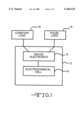
- FIG. 1 is a schematic of an implantable medical device useful with the fuel gauge of the present invention.
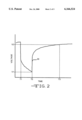
- FIG. 2 is a graph showing the typical pulse signature of a Li/CF x cell.
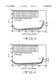
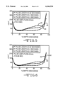
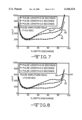
- FIGS. 3 to 8 are graphs constructed from the ⁇ V/ ⁇ T ratio versus % depth-of-discharge for Li/CF x cells under various discharge regimens.
- pulse means a short burst of electrical current of a greater amplitude than that of a current immediately prior to the pulse.
- a pulse train consists of at least two pulses of electrical current delivered in relatively short succession with or without open circuit rest between the pulses.
- FIG. 1 shows a schematic embodiment of an electrochemical cell 10 according to the present invention provided as the power source for an implantable medical device 12.
- Representative medical devices include drug pumps, pacemakers, arterial defibrillators and neurostimulators, and the like.
- the cell 10 is connected to electronic circuitry 14 for the medical device 12.
- the electronics 14 enable the cell 10 to power the medical device 12 both at a relatively constant load 16 in a device monitoring mode, for example in a cardiac pacemaker for monitoring the heartbeat, and at a pulse load 18 during a device operating mode for charging a capacitor (not shown) or for delivering therapy.
- An electrochemical cell that possesses sufficient energy density and discharge capacity required of implantable medical devices comprises an anode of anode active materials selected from Groups IA, IIA and IIIA of the Periodic Table of the Elements, including lithium, sodium, potassium, calcium, magnesium or their alloys, or any alkali metal or alkali-earth metal capable of functioning as an anode.
- Lithium is preferred and in that case the alloys and intermetallic compounds include, for example, Li--Si, Li--Al, Li--Mg, Li--Al--Mg, Li--B and Li--Si--B alloys and intermetallic compounds.
- the form of the anode may vary, but typically, the anode comprises a thin sheet or foil of the anode metal or alloy thereof, and a current collector contacted to the anode material.
- the current collector includes an extended tab or lead for connection to the negative terminal.
- the cathode electrode comprises solid active materials such as are typically used in alkali metal/solid cathode electrochemical cells.
- Particularly preferred cathode active materials for use with the present invention are prepared from fluorine and carbon including graphitic and nongraphitic forms of carbon, such as coke, charcoal or activated carbon.
- the fluorinated carbon is represented by the formula (CF x ) n wherein x varies between about 0.1 to 1.9 and preferably between about 0.5 and 1.2, and (C 2 F) n wherein the n refers to the number of monomer units which can vary widely.
- Electrode active materials suitable for use with the present invention include a metal, a metal oxide, a metal sulfide and carbonaceous materials, and mixtures thereof.
- Such electrode active materials include, but are not limited to, manganese dioxide, copper silver vanadium oxide, silver vanadium oxide, copper vanadium oxide, titanium disulfide, copper oxide, copper sulfide, iron sulfide, iron disulfide and carbon, and mixtures thereof.
- the cathode preferably comprises about 80 to about 99 weight percent of the electrode active material.
- the preferred cathode active mixture comprises CF x combined with a discharge promoter component such as acetylene black, carbon black and/or graphite.
- a discharge promoter component such as acetylene black, carbon black and/or graphite.
- Metallic conductive diluents such as nickel, aluminum, titanium and stainless steel in powder form are also useful when mixed with the cathode active mixture of the present invention. Up to about 10 weight percent of the discharge promoter component/conductive diluent is added to the mixture to improve conductivity.
- Solid cathode active components for incorporation into a cell according to the present invention may be prepared by rolling, spreading or pressing a mixture of one or more of the above listed electrode active materials, a discharge promoter component and/or one or more of the enumerated conductive diluents onto a cathode current collector with the aid of a binder material.
- Preferred binder materials include a powdered fluoro-resin such as powdered polytetrafluoroethylene (PTFE) or powdered polyvinylidene fluoride present at about 1 to about 5 weight percent of the electrode active material.
- the cathode current collector includes a lead for connection to the positive cell terminal, and is preferably in the form of a thin sheet or metal screen, for example, a titanium, stainless steel, aluminum or nickel screen, preferably titanium, having the lead extending therefrom.
- the cathode active mixture including the binder and the discharge promoter component/conductive diluent is formed into a free-standing sheet in a manner similar to that described in U.S. Pat. No. 5,543,249 to Takeuchi et al., which is assigned to the assignee of the present invention and incorporated herein by reference.
- Cathodes prepared as described above may be in the form of a strip wound with a corresponding strip of anode material in a structure similar to a "jellyroll", or in the form of one or more plates operatively associated with at least one or more plates of anode material as in a prismatic configuration. Electrode assemblies having a bobbin shape, a button configuration and the like are also useful with the present invention.
- the electrochemical cell of the present invention further includes a separator disposed intermediate the Group IA, IIA and IIIA anode and the cathode to provide physical separation therebetween.
- the separator is of electrically insulative material and the separator material also is chemically unreactive with the anode and cathode active materials and both chemically unreactive with and insoluble in the electrolyte.
- the separator material has a degree of porosity sufficient to allow flow therethrough of the electrolyte during the electrochemical reaction of the electrochemical cell.
- Illustrative separator materials include woven and non-woven fabrics of polyolefinic fibers including polyvinylidene fluoride, polyethylenetetrafluoroethylene, and polyethylenechlorotrifluoroethylene laminated or superposed with a polyolefinic or fluoropolymeric microporous film, non-woven glass, glass fiber materials and ceramic materials.
- Suitable microporous films include a polytetrafluoroethylene membrane commercially available under the designation ZITEX (Chemplast Inc.), a polypropylene membrane commercially available under the designation CELGARD (Celanese Plastic Company, Inc.) and a membrane commercially available under the designation DEXIGLAS (C.H. Dexter, Div., Dexter Corp.).
- the electrochemical cell of the present invention further includes a nonaqueous, ionically conductive electrolyte which serves as a medium for migration of ions between the anode and the cathode electrodes during the electrochemical reactions of the cell.
- the electrochemical reaction at the electrodes involves conversion of ions in atomic or molecular forms which migrate from the anode to the cathode.
- nonaqueous electrolytes suitable for the present invention are substantially inert to the anode and cathode materials, and they exhibit those physical properties necessary for ionic transport, namely, low viscosity, low surface tension and wettability.
- a suitable electrolyte has an inorganic or organic, tonically conductive salt dissolved in a nonaqueous solvent, and more preferably, the electrolyte includes an ionizable alkali metal salt dissolved in a mixture of aprotic organic solvents comprising a low viscosity solvent and a high permittivity solvent or, a single solvent.
- the ionically conductive salt serves as the vehicle for migration of the anode ions to intercalate or react with the cathode active material.
- the preferred ion-forming alkali metal salt is similar to the alkali metal comprising the anode.
- salts useful with the present invention include LiPF 6 , LiAsF 6 , LiSbF 6 , LiBF 4 , LiAlC 4 , LiO 2 , LiGaCl 4 , LiSO 3 F, LiB(C 6 H 5 ) 4 , LiClO 4 , LiC(SO 2 CF 3 ) 3 , LiSCN, LiO 3 SCF 2 CF 3 , LiC 6 F 5 SO 3 , LiO 2 CCF 3 , LiN(SO 2 CF 3 ) 2 and LiCF 3 SO 3 , and mixtures thereof.
- Low viscosity solvents include tetrahydrofuran (TFH), methyl acetate (MA), diglyme, trigylme, tetragylme, dimethyl carbonate (DMC), 1,2-dimethoxyethane (DME), diethyl carbonate, diisopropylether, 1,2-diethoxyethane (DEE), 1-ethoxy, 2-methoxyethane (EME), dipropyl carbonate (DPC), ethyl methyl carbonate (EMC), methyl propyl carbonate (MPC) and ethyl propyl carbonate (EPC), and mixtures thereof, and high permittivity solvents include cyclic carbonates, cyclic esters and cyclic amides such as propylene carbonate (PC), butylene carbonate (BC), ethylene carbonate (EC), acetonitrile, dimethyl sulfoxide, dimethyl formamide, dimethyl acetamide, ⁇ -valerolactone, ⁇
- the preferred form of the electrochemical cell of the present invention is a case-negative design wherein the anode/cathode couple is provided in a prismatic configuration inserted into a conductive metal casing such that the casing, a header thereof, or both are connected to the anode current collector and serve as the negative cell terminal, as is well known to those skilled in the art.
- a preferred material for the casing is titanium although stainless steel, nickel and aluminum are suitable.
- the casing header has a sufficient number of openings to accommodate a glass-to-metal seal terminal pin feedthrough for the cathode electrode. An additional opening is provided for electrolyte filling.
- the cell is filled with the electrolyte solution described hereinabove and hermetically sealed such as by close-welding a stainless steel plug over the fill hole, but not limited thereto.
- the cell of the present invention can also be constructed in a case-positive design.
- Li/CF x lithium/carbon monofluoride cells commercially available under model no. 9424 from Wilson Greatbatch Ltd., Clarence, N.Y., the assignee of the present invention, were selected from production inventory for pulse discharge testing. These cells have a half-round profile with external dimensions of 45 mm ⁇ 22 mm ⁇ 5 mm and a theoretical capacity of 1.32 Ah.
- the selected Li/CF x cells are fabricated for use in implantable medical applications and they are capable of providing currents in the microamp to milliamp range while offering high energy density, long shelf life, and low impedance throughout cell life.
- the Li/CF x couple is characterized by a relatively flat voltage discharge profile.
- the cells were discharged at 37° C. for 9 hours under a 1.5 kohm constant resistance load during an initial predischarge period.
- the predischarge period depleted the cells of approximately 1% of their theoretical capacity.
- the cells were placed on open circuit storage for one week at 37° C., after which time the cells were subjected to a 10 mA pulse train.
- This pulse train consisted of four, 10 second pulses, with 15 second rest intervals between pulses.
- Pulse train 1 was applied to the cells immediately (one cell at a time) under the 100 kohm background load. Subsequent pulse trains were applied every 0.06 Ah.
- each pulse train consisted of 9 pulses applied in parallel with the 100 kohm load that had been soldered to the cells.
- the maximum contribution of the 100 kohm load was calculated to be approximately 28 microamps. Therefore, the stated pulse amplitudes do not account for the 100 kohm load.
- the cells reached end-of-life during pulse trains 22 or 23.
- FIG. 2 is a graph showing the typical pulse signature of a Li/CF x cell (curve 30) wherein the pulse length is equal to (T2-T1) and recovery time is equal to (T3-T2). Voltage change is equal to (V2-V1).
- pulse application and voltage recovery [(T2-T1) plus (T3-T2)] were required to be within a total of 0.83 seconds (corresponding to 72 heartbeats per minute).
- the pulse length (T2-T1) and recovery time (T3-T2) must be less than 0.83 seconds excludes from consideration those pulses having a 2 second pulse length, namely, curves 36, 42, 48, 54, 60 and 66, as well as those pulses having a 0.2 second pulse length with a 0.68 second recovery, namely, curves 40, 52 and 64.
- FIGS. 3 and 4 compare against FIGS. 3 and 4 (for a 0.5 mA pulse) or FIGS. 5 and 6 (for a 5 mA pulse).
- the present invention describes a method for determining the remaining discharge capacity in an alkali metal cell powering an electronic device such as an implantable medical device. While the example is directed to Li/CF x cells, the method for determining the remaining discharge capacity according to the present invention is believed to be applicable to all pulse dischargeable alkali metal/solid cathode cells.
- Exemplary electrochemical couples include Li/SVO, Li/CSVO and Li/MnO 2 as well as lithium and the other cathode active materials described hereinabove.
- Such a "fuel gauge" is useful for determining and planning elective surgery when the power source for the medical device is approaching its end-of-life and needs to be replaced.
Abstract
Description
              TABLE 1
______________________________________
Pulse #   Pulse Length (sec)
                       Pulse Amplitude (mA)
______________________________________
1         0.02         0.5
2         0.02         5
3         0.02         20
4         0.2          0.5
5         0.2          5
6         0.2          20
7         2            0.5
8         2            5
9         2            20
______________________________________
% Depth of Discharge=[(delivered capacity/theoretical capacity)*100].
Claims (29)
Priority Applications (3)
| Application Number | Priority Date | Filing Date | Title |
|---|---|---|---|
| US09/521,309 US6166524A (en) | 2000-03-09 | 2000-03-09 | Alternate fuel gauge for an alkali metal electrochemical cell |
| EP01301901A EP1170810A3 (en) | 2000-03-09 | 2001-03-01 | Alternate fuel gauge for an alkali metal electrochemical cell |
| JP2001065413A JP2001313043A (en) | 2000-03-09 | 2001-03-08 | Fuel gauge for alkali metal electrochemical cell |
Applications Claiming Priority (1)
| Application Number | Priority Date | Filing Date | Title |
|---|---|---|---|
| US09/521,309 US6166524A (en) | 2000-03-09 | 2000-03-09 | Alternate fuel gauge for an alkali metal electrochemical cell |
Publications (1)
| Publication Number | Publication Date |
|---|---|
| US6166524A true US6166524A (en) | 2000-12-26 |
Family
ID=24076238
Family Applications (1)
| Application Number | Title | Priority Date | Filing Date |
|---|---|---|---|
| US09/521,309 Expired - Fee Related US6166524A (en) | 2000-03-09 | 2000-03-09 | Alternate fuel gauge for an alkali metal electrochemical cell |
Country Status (3)
| Country | Link |
|---|---|
| US (1) | US6166524A (en) |
| EP (1) | EP1170810A3 (en) |
| JP (1) | JP2001313043A (en) |
Cited By (21)
| Publication number | Priority date | Publication date | Assignee | Title |
|---|---|---|---|---|
| EP1132991A2 (en) * | 2000-03-09 | 2001-09-12 | Wilson Greatbatch Limited | Fuel gauge for an alkali metal electrochemical cell |
| EP1170810A2 (en) * | 2000-03-09 | 2002-01-09 | Wilson Greatbatch Ltd. | Alternate fuel gauge for an alkali metal electrochemical cell |
| EP1306686A2 (en) * | 2001-10-23 | 2003-05-02 | Wilson Greatbatch Technologies, Inc. | Method for determining poor performing cells |
| US20040051504A1 (en) * | 2002-09-09 | 2004-03-18 | Kenneth Syracuse | Discharge methodologies for optimizing the performance of lithium/silver vanadium oxide cells |
| US20040151976A1 (en) * | 2003-01-23 | 2004-08-05 | Marcus Palazzo | Electrochemical treatment method to reduce voltage delay and cell resistance in lithium/silver vanadium oxide cells |
| US20050007073A1 (en) * | 2003-07-11 | 2005-01-13 | James Kristofer J. | Indicator of remaining energy in storage cell of implantable medical device |
| US20050102005A1 (en) * | 2003-11-12 | 2005-05-12 | Krig David B. | System and method for monitoring or reporting battery status of implantable medical device |
| US20050216212A1 (en) * | 2004-03-23 | 2005-09-29 | Kenneth Syracuse | Method for estimating long term end-of-life characteristics using short-term data for lithium/silver vanadium oxide cells |
| US7263449B1 (en) * | 2001-10-23 | 2007-08-28 | Greatbatch Ltd. | Method for determining poor performing cells |
| US20120025785A1 (en) * | 2009-02-09 | 2012-02-02 | Dow Kokam France Sas | Method for managing the heat in an electric battery |
| US8198863B1 (en) | 2006-12-13 | 2012-06-12 | Maxim Integrated Products, Inc. | Model-based battery fuel gauges and methods |
| US8203305B1 (en) * | 2008-07-02 | 2012-06-19 | Maxim Integrated Products, Inc. | Enhanced voltage-based fuel gauges and methods |
| US20120299556A1 (en) * | 2010-06-18 | 2012-11-29 | Tomoyasu Ishikawa | Deterioration degree determining apparatus |
| US8338012B2 (en) | 2009-02-09 | 2012-12-25 | Dow Kokam France Sas | Method for managing the heat in an electric battery |
| US8598849B2 (en) * | 2009-10-19 | 2013-12-03 | Apple Inc. | In-situ battery health detector and end-of-life indicator |
| CN104237798A (en) * | 2014-08-28 | 2014-12-24 | 浙江天能电池江苏新能源有限公司 | Lead storage battery accelerated life detection method |
| US9035616B2 (en) | 2010-12-07 | 2015-05-19 | Maxim Integrated Products, Inc. | State based full and empty control for rechargeable batteries |
| CN105223504A (en) * | 2014-05-30 | 2016-01-06 | Tcl集团股份有限公司 | A kind of evaluation method of electric quantity of lithium battery and system |
| CN108693477A (en) * | 2017-04-10 | 2018-10-23 | 李尔公司 | The method and system calculated for battery charging state |
| CN109264197A (en) * | 2018-08-22 | 2019-01-25 | 佛山豆萁科技有限公司 | Individual privacy information security protection suit |
| CN112490422A (en) * | 2020-11-10 | 2021-03-12 | 华南理工大学 | Rod-shaped porous cobaltosic oxide/nanotube manganese dioxide cathode material and preparation method and application thereof |
Families Citing this family (2)
| Publication number | Priority date | Publication date | Assignee | Title |
|---|---|---|---|---|
| JP7239351B2 (en) * | 2019-03-08 | 2023-03-14 | Fdk株式会社 | Depth of discharge estimation method and depth of discharge estimation device for lithium primary battery |
| JP7231801B2 (en) * | 2019-03-22 | 2023-03-02 | Fdk株式会社 | OCV characteristic estimation method and OCV characteristic estimation device |
Citations (5)
| Publication number | Priority date | Publication date | Assignee | Title |
|---|---|---|---|---|
| US4556061A (en) * | 1982-08-18 | 1985-12-03 | Cordis Corporation | Cardiac pacer with battery consumption monitor circuit |
| US4607932A (en) * | 1984-04-28 | 1986-08-26 | Canon Kabushiki Kaisha | Battery checking device |
| US5144218A (en) * | 1989-10-25 | 1992-09-01 | U.S. Philips Corporation | Device for determining the charge condition of a battery |
| US5284719A (en) * | 1992-07-08 | 1994-02-08 | Benchmarq Microelectronics, Inc. | Method and apparatus for monitoring battery capacity |
| US5357203A (en) * | 1992-07-08 | 1994-10-18 | Benchmarq Microelectronics, Inc. | Battery monitoring circuit for operating with high battery discharge rates |
Family Cites Families (3)
| Publication number | Priority date | Publication date | Assignee | Title |
|---|---|---|---|---|
| US5739670A (en) * | 1996-10-31 | 1998-04-14 | General Motors Corporation | Method for diagnosing battery condition |
| US6281683B1 (en) * | 1999-02-02 | 2001-08-28 | Enrev Corporation | Rapid determination of present and potential battery capacity |
| US6166524A (en) * | 2000-03-09 | 2000-12-26 | Wilson Greatbatch Ltd. | Alternate fuel gauge for an alkali metal electrochemical cell |
-
2000
- 2000-03-09 US US09/521,309 patent/US6166524A/en not_active Expired - Fee Related
-
2001
- 2001-03-01 EP EP01301901A patent/EP1170810A3/en not_active Withdrawn
- 2001-03-08 JP JP2001065413A patent/JP2001313043A/en active Pending
Patent Citations (5)
| Publication number | Priority date | Publication date | Assignee | Title |
|---|---|---|---|---|
| US4556061A (en) * | 1982-08-18 | 1985-12-03 | Cordis Corporation | Cardiac pacer with battery consumption monitor circuit |
| US4607932A (en) * | 1984-04-28 | 1986-08-26 | Canon Kabushiki Kaisha | Battery checking device |
| US5144218A (en) * | 1989-10-25 | 1992-09-01 | U.S. Philips Corporation | Device for determining the charge condition of a battery |
| US5284719A (en) * | 1992-07-08 | 1994-02-08 | Benchmarq Microelectronics, Inc. | Method and apparatus for monitoring battery capacity |
| US5357203A (en) * | 1992-07-08 | 1994-10-18 | Benchmarq Microelectronics, Inc. | Battery monitoring circuit for operating with high battery discharge rates |
Cited By (38)
| Publication number | Priority date | Publication date | Assignee | Title |
|---|---|---|---|---|
| EP1170810A2 (en) * | 2000-03-09 | 2002-01-09 | Wilson Greatbatch Ltd. | Alternate fuel gauge for an alkali metal electrochemical cell |
| US6377850B1 (en) * | 2000-03-09 | 2002-04-23 | Wilson Greatbatch Ltd. | Fuel gauge for an alkali metal electrochemical cell |
| EP1132991A3 (en) * | 2000-03-09 | 2002-09-04 | Wilson Greatbatch Limited | Fuel gauge for an alkali metal electrochemical cell |
| EP1170810A3 (en) * | 2000-03-09 | 2003-05-07 | Wilson Greatbatch Ltd. | Alternate fuel gauge for an alkali metal electrochemical cell |
| EP1132991A2 (en) * | 2000-03-09 | 2001-09-12 | Wilson Greatbatch Limited | Fuel gauge for an alkali metal electrochemical cell |
| EP1306686A2 (en) * | 2001-10-23 | 2003-05-02 | Wilson Greatbatch Technologies, Inc. | Method for determining poor performing cells |
| EP1306686A3 (en) * | 2001-10-23 | 2004-01-14 | Wilson Greatbatch Technologies, Inc. | Method for determining poor performing cells |
| US7263449B1 (en) * | 2001-10-23 | 2007-08-28 | Greatbatch Ltd. | Method for determining poor performing cells |
| US6930468B2 (en) | 2002-09-09 | 2005-08-16 | Wilson Greatbatch Technologies, Inc. | Discharge methodologies for optimizing the performance of lithium/silver vanadium oxide cells |
| US20040051504A1 (en) * | 2002-09-09 | 2004-03-18 | Kenneth Syracuse | Discharge methodologies for optimizing the performance of lithium/silver vanadium oxide cells |
| EP1411578A1 (en) * | 2002-09-09 | 2004-04-21 | Wilson Greatbatch Technologies, Inc. | Discharge methodologies for optimizing the performance of alkali metal/silver vanadium oxide cells |
| US20040151976A1 (en) * | 2003-01-23 | 2004-08-05 | Marcus Palazzo | Electrochemical treatment method to reduce voltage delay and cell resistance in lithium/silver vanadium oxide cells |
| US7026791B2 (en) * | 2003-01-23 | 2006-04-11 | Wilson Greatbatch Technologies, Inc. | Electrochemical treatment method to reduce voltage delay and cell resistance in lithium/silver vanadium oxide cells |
| US7239146B2 (en) * | 2003-07-11 | 2007-07-03 | Cardiac Pacemakers, Inc. | Indicator of remaining energy in storage cell of implantable medical device |
| US20050007073A1 (en) * | 2003-07-11 | 2005-01-13 | James Kristofer J. | Indicator of remaining energy in storage cell of implantable medical device |
| US20050102005A1 (en) * | 2003-11-12 | 2005-05-12 | Krig David B. | System and method for monitoring or reporting battery status of implantable medical device |
| US7194308B2 (en) | 2003-11-12 | 2007-03-20 | Cardiac Pacemakers, Inc. | System and method for monitoring or reporting battery status of implantable medical device |
| US20050216212A1 (en) * | 2004-03-23 | 2005-09-29 | Kenneth Syracuse | Method for estimating long term end-of-life characteristics using short-term data for lithium/silver vanadium oxide cells |
| US7092830B2 (en) * | 2004-03-23 | 2006-08-15 | Wilson Greatbatch Technologies, Inc. | Method for estimating long term end-of-life characteristics using short-term data for lithium/silver vanadium oxide cells |
| US8198863B1 (en) | 2006-12-13 | 2012-06-12 | Maxim Integrated Products, Inc. | Model-based battery fuel gauges and methods |
| US8502504B1 (en) | 2006-12-13 | 2013-08-06 | Maxim Integrated Products, Inc. | Model-based battery fuel gauges and methods |
| US8643331B1 (en) * | 2008-07-02 | 2014-02-04 | Maxim Integrated Products, Inc. | Enhanced voltage-based fuel gauges and methods |
| US8203305B1 (en) * | 2008-07-02 | 2012-06-19 | Maxim Integrated Products, Inc. | Enhanced voltage-based fuel gauges and methods |
| US8395358B2 (en) * | 2009-02-09 | 2013-03-12 | Dow Kokam France Sas | Method for managing the heat in an electric battery |
| US20120025785A1 (en) * | 2009-02-09 | 2012-02-02 | Dow Kokam France Sas | Method for managing the heat in an electric battery |
| US8338012B2 (en) | 2009-02-09 | 2012-12-25 | Dow Kokam France Sas | Method for managing the heat in an electric battery |
| US8598849B2 (en) * | 2009-10-19 | 2013-12-03 | Apple Inc. | In-situ battery health detector and end-of-life indicator |
| US20120299556A1 (en) * | 2010-06-18 | 2012-11-29 | Tomoyasu Ishikawa | Deterioration degree determining apparatus |
| US9791517B2 (en) | 2010-12-07 | 2017-10-17 | Maxim Integrated Products, Inc. | State based full and empty control for rechargeable batteries |
| US10139452B2 (en) | 2010-12-07 | 2018-11-27 | Maxim Integraqted Products, Inc. | State based full and empty control for rechargeable batteries |
| US9035616B2 (en) | 2010-12-07 | 2015-05-19 | Maxim Integrated Products, Inc. | State based full and empty control for rechargeable batteries |
| CN105223504A (en) * | 2014-05-30 | 2016-01-06 | Tcl集团股份有限公司 | A kind of evaluation method of electric quantity of lithium battery and system |
| CN105223504B (en) * | 2014-05-30 | 2018-03-16 | Tcl集团股份有限公司 | The evaluation method and system of a kind of electric quantity of lithium battery |
| CN104237798B (en) * | 2014-08-28 | 2017-04-05 | 浙江天能电池江苏新能源有限公司 | A kind of lead battery accelerated aging detection method |
| CN104237798A (en) * | 2014-08-28 | 2014-12-24 | 浙江天能电池江苏新能源有限公司 | Lead storage battery accelerated life detection method |
| CN108693477A (en) * | 2017-04-10 | 2018-10-23 | 李尔公司 | The method and system calculated for battery charging state |
| CN109264197A (en) * | 2018-08-22 | 2019-01-25 | 佛山豆萁科技有限公司 | Individual privacy information security protection suit |
| CN112490422A (en) * | 2020-11-10 | 2021-03-12 | 华南理工大学 | Rod-shaped porous cobaltosic oxide/nanotube manganese dioxide cathode material and preparation method and application thereof |
Also Published As
| Publication number | Publication date |
|---|---|
| JP2001313043A (en) | 2001-11-09 |
| EP1170810A3 (en) | 2003-05-07 |
| EP1170810A2 (en) | 2002-01-09 |
Similar Documents
| Publication | Publication Date | Title |
|---|---|---|
| US6166524A (en) | Alternate fuel gauge for an alkali metal electrochemical cell | |
| US6171729B1 (en) | Control of swelling in alkali metal electrochemical cells | |
| US6627337B2 (en) | Conversion of low rate energy into high rate energy by parallel discharging | |
| US6221534B1 (en) | Alkali metal electrochemical cell having an improved cathode activated with a nonaqueous electrolyte having a carbonate additive | |
| US6228534B1 (en) | Annealing of mixed metal oxide electrodes to reduce polarization resistance | |
| US6551747B1 (en) | Sandwich cathode design for alkali metal electrochemical cell with high discharge rate capability | |
| US5667916A (en) | Mixed cathode formulation for achieving end-of-life indication | |
| US7776470B2 (en) | Anode-to-cathode capacity ratios for SVO/CF x hybrid cathode electrochemical cells | |
| US7018743B2 (en) | Dual chemistry electrode design | |
| US6677077B2 (en) | Electrochemical cell having multiplate electrodes with differing discharge rate regions | |
| US6926991B2 (en) | SVO/CFx parallel cell design within the same casing | |
| US6936379B2 (en) | Method for electrode design for implantable device applications that require the elective replacement indicator (ERI) | |
| US7092830B2 (en) | Method for estimating long term end-of-life characteristics using short-term data for lithium/silver vanadium oxide cells | |
| US6607861B2 (en) | Application of γ-SVO and mixture of γ-SVO/ε-SVO in high rate electrochemical lithium cells containing SVO/CFx/SVO sandwich cathodes | |
| US20030134188A1 (en) | Sandwich electrode design having relatively thin current collectors | |
| US6377850B1 (en) | Fuel gauge for an alkali metal electrochemical cell | |
| US20020062138A1 (en) | Double current collector cathode design using the same active material in varying thicknesses for alkali metal or ION electrochemical cells | |
| US20030113613A1 (en) | High energy density rechargeable cell for medical device applications | |
| US6801016B2 (en) | Matching cells for a battery pack | |
| US20030113632A1 (en) | Oxidized titanium as a cathodic current collector | |
| US7056358B2 (en) | Method for using high rate lithium electrochemical cell containing SVO/CFchi/SVo sandwich cathodes having γ-SVO and mixture of γ-SVO/ε-SVO |
Legal Events
| Date | Code | Title | Description |
|---|---|---|---|
| AS | Assignment |
Owner name: WILSON GREATBATCH LTD., NEW YORK Free format text: ASSIGNMENT OF ASSIGNORS INTEREST;ASSIGNORS:TAKEUCHI, ESTHER S.;WAITE, NOELLE M.;SYRACUSE, KENNETH C.;REEL/FRAME:010670/0419;SIGNING DATES FROM 20000225 TO 20000309 |
|
| AS | Assignment |
Owner name: MANUFACTURERS AND TRADERS TRUST COMPANY, NEW YORK Free format text: SECURITY INTEREST;ASSIGNOR:WILSON GREATBATCH LTD.;REEL/FRAME:011700/0831 Effective date: 20010112 |
|
| FPAY | Fee payment |
Year of fee payment: 4 |
|
| AS | Assignment |
Owner name: GREATBATCH, LTD. (NEW YORK CORPORATION), NEW YORK Free format text: CHANGE OF NAME;ASSIGNOR:WILSON GREATBATCH,TD.;REEL/FRAME:019520/0743 Effective date: 20050524 |
|
| AS | Assignment |
Owner name: MANUFACTURERS AND TRADERS TRUST COMPANY, NEW YORK Free format text: SECURITY INTEREST;ASSIGNOR:GREATBATCH LTD.;REEL/FRAME:020571/0205 Effective date: 20070522 Owner name: MANUFACTURERS AND TRADERS TRUST COMPANY,NEW YORK Free format text: SECURITY INTEREST;ASSIGNOR:GREATBATCH LTD.;REEL/FRAME:020571/0205 Effective date: 20070522 |
|
| REMI | Maintenance fee reminder mailed | ||
| LAPS | Lapse for failure to pay maintenance fees | ||
| STCH | Information on status: patent discontinuation |
Free format text: PATENT EXPIRED DUE TO NONPAYMENT OF MAINTENANCE FEES UNDER 37 CFR 1.362 |
|
| FP | Lapsed due to failure to pay maintenance fee |
Effective date: 20081226 |
|
| AS | Assignment |
Owner name: WILSON GREATBATCH LTD., NEW YORK Free format text: RELEASE BY SECURED PARTY;ASSIGNOR:MANUFACTURERS AND TRADERS TRUST COMPANY;REEL/FRAME:058224/0190 Effective date: 20210903 |
|
| AS | Assignment |
Owner name: GREATBATCH LTD., NEW YORK Free format text: RELEASE BY SECURED PARTY;ASSIGNOR:MANUFACTURERS AND TRADERS TRUST COMPANY (AS ADMINISTRATIVE AGENT);REEL/FRAME:058574/0437 Effective date: 20210903 |