US6157733A - Integration of monocular cues to improve depth perception - Google Patents
Integration of monocular cues to improve depth perception Download PDFInfo
- Publication number
- US6157733A US6157733A US08/844,422 US84442297A US6157733A US 6157733 A US6157733 A US 6157733A US 84442297 A US84442297 A US 84442297A US 6157733 A US6157733 A US 6157733A
- Authority
- US
- United States
- Prior art keywords
- image
- objects
- foreground
- background
- shadow
- Prior art date
- Legal status (The legal status is an assumption and is not a legal conclusion. Google has not performed a legal analysis and makes no representation as to the accuracy of the status listed.)
- Expired - Lifetime
Links
Images


Classifications
-
- G—PHYSICS
- G06—COMPUTING; CALCULATING OR COUNTING
- G06T—IMAGE DATA PROCESSING OR GENERATION, IN GENERAL
- G06T15/00—3D [Three Dimensional] image rendering
- G06T15/02—Non-photorealistic rendering
-
- G—PHYSICS
- G06—COMPUTING; CALCULATING OR COUNTING
- G06T—IMAGE DATA PROCESSING OR GENERATION, IN GENERAL
- G06T15/00—3D [Three Dimensional] image rendering
-
- A—HUMAN NECESSITIES
- A63—SPORTS; GAMES; AMUSEMENTS
- A63F—CARD, BOARD, OR ROULETTE GAMES; INDOOR GAMES USING SMALL MOVING PLAYING BODIES; VIDEO GAMES; GAMES NOT OTHERWISE PROVIDED FOR
- A63F2300/00—Features of games using an electronically generated display having two or more dimensions, e.g. on a television screen, showing representations related to the game
- A63F2300/60—Methods for processing data by generating or executing the game program
- A63F2300/66—Methods for processing data by generating or executing the game program for rendering three dimensional images
- A63F2300/6646—Methods for processing data by generating or executing the game program for rendering three dimensional images for the computation and display of the shadow of an object or character
Definitions
- the present invention relates to image processing, and more particularly to a novel approach for using monocular cues acquired from a single two dimensional image to improve depth perception.
- Binocular methods are discussed in D. Marr and T. Poggio, "Cooperative Computation of Stereo Disparity," Science, vol. 194, pp. 283-287 (1976) and S. Barnard and M. Fischler, “Computational Stereo,” Computing Surveys, vol. 14, no. 4, pp. 553-572 (December, 1982). Binocular depth cues, such as disparity, required multiple images (i.e., a stereo pair of images) and matching of corresponding points, which is a computationally complex and error-prone task. More recently, researchers have developed monocular approaches by comparing images using differing apertures, as discussed in A.
- Pentland "a New Sense For Depth of Field,” IEEE Transactions on Pattern Analysis and Machine Intelligence,” vol. 9, no. 4 (July, 1987) and G. Surya and M. Subbarao, “Depth From Defocus By Changing Camera Aperture: a Spatial Domain Approach,” Proceedings of IEEE Transactions on Pattern Analysis and Machine Intelligence, pp. 61-67 (1993).
- Monocular depth cues such as blur, have been used to perceive depth. In these approaches, point matching was not required, but multiple images were required for depth perception.
- the image processing techniques of the present invention for modifying an image to enhance depth effect improve upon the prior art by using only monocular cues which are extracted from a single image.
- the image processing techniques of the present invention involve extracting one or more depth cues from a single two-dimensional image, and then combining these cues to create a three-dimensional effect.
- an original image is acquired and stored in memory.
- objects in the original image are identified and segmented.
- a segmentation map can be generated which identifies each object in the original image.
- Each object in the original image is then identified as being either in the foreground or in the background.
- An object of interest is identified (usually located in the foreground).
- One or more depth cues are then extracted from the original image, including shading, brightness, blur and occlusion cues.
- the depth cues may be in the form of one or more intermediate images having an improved depth effect.
- a shadow can be generated by extracting the shape of the object of interest in the foreground and darkening it to grey like a shadow.
- An intermediate shadow image is generated by applying the darkened shadow to the background or one or more background objects to create a shading effect.
- An intermediate brightness image can be created by increasing the relative intensity or brightness of the object of interest.
- An intermediate blur image can be generated by blurring the original image, or by blurring all objects other than the object of interest.
- One or more of the intermediate images may be combined to generate a combined image.
- the combined image is then further enhanced by enlarging the object of interest, thereby further occluding the other objects in the combined image.
- each of the four cues can be extracted and applied sequentially to the original image, and without generating intermediate images. It is not necessary to apply all four depth cues to achieve an enhanced depth effect.
- One or more of the cues can be applied to enhance depth. A plurality of depth cues should be combined for optimum results.
- FIG. 1 illustrates a flow chart for modifying an image using monocular cues to improve depth perception according to an embodiment of the present invention.
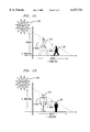
- FIGS. 2A and 2B illustrate a technique for creating a shadow of an object of interest and casting the shadow onto a background object according to an embodiment of the present invention.
- FIG. 3 illustrates a method for increasing or decreasing the size of an image according to an embodiment of the present invention.
- FIGS. 4A-4E illustrate the application of blur, shading and brightness depth cues according to an embodiment of the present invention to enhance depth perception.
- FIGS. 5A-5D illustrate the application of blur and occlusion depth cues according to an embodiment of the present invention to enhance depth perception.
- FIG. 6 illustrates a block diagram of an embodiment of a computer system which may be used to implement the present invention.
- FIG. 1 illustrates a flow chart for modifying an image using monocular cues to improve depth perception according to an embodiment of the present invention.
- Depth cues are used to perceive depth and dimensionality.
- the present invention involves extracting the depth cues from a single two-dimensional image, and then combining these cues to create a three-dimensional effect.
- the depth cues used to improve depth perception are shading, brightness, blur and occlusion. Other depth cues could also be used.
- an image is acquired using a camera or a similar device.
- This original image is digitized (if not already in digital form) and stored in memory.
- the image can be a bit-mapped image of N ⁇ N pixels.
- Each pixel has an associated intensity or brightness for a monochrome image (i.e., grey scale) or an associated color for a color image.
- Each pixel in a monochrome image can be represented, for example, using eight bits, providing 256 intensity values from 0 to 255, with 0 being the darkest or lowest intensity and 255 being the brightest or highest intensity.
- step 120 the original image is segmented into one or more objects.
- Objects in an image can be segmented using available techniques.
- separate images of several objects i.e., a person, a book and a desk
- a computer can then identify each object in the original image by matching the objects (i.e., matching the shape and/or color/intensity of the objects) in each of the separate images to the objects in the original image.
- a second technique for segmenting objects is to segment or group pixels in close proximity to each other which have the same (or approximately the same) intensity or color.
- a third technique can be used to segment objects based on detected motion. Using this third technique, a plurality of successive frames of the same image are taken over a period of time from the same point and stored. The intensity or color of corresponding pixels of each frame are compared to identify any pixels which have changed (indicating motion). Pixels which have changed and which are in close proximity to each other can be grouped together as one or more segmented objects.
- a segmentation map is generated for each segmented object identifying the location and boundaries of each object in the original image.
- a segmentation map for example, can be a binary image in which the object is white (i.e., a pixel value of 255), and all else is black.
- Each of the objects in the original image are then identified as being either in the foreground or the background. This can be performed manually by inspecting the original image. Also, one or more objects of interest in the original image can be identified. Typically, the object of interest is a person or item in the foreground of the image.
- a shadow of the object(s) of interest (or an object in the foreground) is generated from the original image. Shading (i.e., use of a shadow) improves depth perception because the object casting the shadow appears to be in front of the object on which the shadow has been cast.
- the shadow can be generated by extracting the shape of the object of interest in the foreground and darkening it to grey like a shadow.
- step 140 the generated shadow is then applied to background objects in the original image to create an intermediate shadow image. It is most beneficial to use shading to improve depth perception when background objects are close enough to have a shadow cast on them. As a result, it may not be effective to use the shading cue when the background objects are too far away from the foreground object of interest.
- step 150 the brightness or intensity of the foreground object of interest in the original image is increased to create an intermediate brightness image.
- the present invention exaggerates the brightness of closer objects by increasing their intensities. For example, all pixels of the object(s) of interest may be increased by 20 (for pixel intensities ranging from 0 to 255).
- the brightness cue can always be used to improve depth perception regardless of the relative location of background objects compared to the location of the foreground object of interest. Alternatively, all objects other than the object of interest can be decreased in intensity to achieve the brightness effect.
- one or more objects are blurred to create an intermediate blur image.
- Blur is a measure of loss of detail in an image. In the blur cue, when an object is in focus, other objects are blurred. The amount of blur depends on the distance from the focused object. In the present invention, one or more objects (or portions thereof) are blurred to exaggerate the depth of objects in the image. Blurring can always be used regardless of the relative location of the object of interest. Blurring is the most effective cue in enhancing depth perception.
- Different blurring techniques can be used to exaggerate the depth of objects in an image.
- a first blurring technique the foreground object of interest is removed from the original image. The remaining image is then blurred. The object of interest is then superimposed on the remaining image to create the intermediate blur image. Alternatively, it is unnecessary to remove the foreground object of interest.
- the (focused) foreground object of interest can be copied, and then superimposed over the entire blurred image to achieve the desired depth effect.
- a second blurring technique uses radial blurring of the image.
- a point on the original image which is closest to the viewer is selected, such as the edge of a book or a person's nose.
- the selected point is not blurred because it is the closest point in the image and should remain in focus.
- the entire original image is increasingly blurred outwardly or radially from the selected point.
- the amount of blurring in the image increases in proportion to the distance from the selected point.
- the entire image (other than the selected point or area) can be blurred a fixed amount.
- a blurred image is the response of the camera to a single point source. This response is called the camera point spread function (PSF), h(x,y), which can be approximated as a Gaussian function: ##EQU1##
- a blurred image g(x,y) can be generated by convolving an original focused image f(x,y) with the PSF h(x,y):
- ⁇ is a constant chosen by the user to affect blurring.
- ⁇ is the variance.
- h(x,y) affects the width or range of pixels blurred.
- step 170 all three depth-enhanced intermediate images are combined.
- the intermediate images can be combined additively by adding the corresponding pixel values from the three intermediate depth-enhanced images.
- Each of the cumulative pixel values is then divided by three. Therefore, there is equal contribution from the shading cue, the brightness cue and the blur cue to generate the combined image.
- the cues may be weighted unequally. For example, because blur can be the most effective cue, the blur cue can be given more weight than the other cues. For example, this can be done by multiplying pixel values of the intermediate blur image by 2, adding the pixel values of the intermediate blur image to the other intermediate pixel values, and then dividing the cumulative pixel values by 4 to give more weight to the blur cue. In this example, the blur cue contributes 50%, while, the shading and brightness cues each contribute 25%.
- step 180 the foreground object of interest is increased in size to occlude or block even more of other objects in the combined image. Occlusion indicates that the occluded object is farther away from the occluding object (the object of interest).
- An embodiment of the present invention generates the occlusion effect by enlarging or increasing the size of the foreground object of interest to make the foreground object of interest appear closer. Alternatively, the remaining (background) objects can be decreased in size to provide the same occlusion effect.
- the step 180 (occlusion) should be performed after combining the other three cues (intermediate depth-enhanced images) because step 180 changes the geometry of the image.
- the method of FIG. 1 illustrates only one embodiment of the present invention for improving depth perception of an image using monocular cues extracted from a single image. According to the present invention, other methods using monocular cues similar to FIG. 1 may be employed to improve depth perception. For example, while the embodiment of FIG. 1 uses all four depth cues (shading, brightness, blur and occlusion) to improve depth perception, any combination of one or more of the depth cues can be used to improve depth perception. These cues can be performed or applied to the original image in any order. Also, the method illustrated in FIG. 1 generates three intermediate images in parallel at steps 140, 150 and 160. Alternatively, each depth cue may be applied to the original image sequentially or serially and without generating intermediate images.
- depth cue may be applied to the original image sequentially or serially and without generating intermediate images.
- FIGS. 2A and 2B illustrate an embodiment for creating a shadow of an object of interest and casting the shadow onto a background object (steps 130 and 140, FIG. 1).
- an object of interest such as a person
- the person's shadow 220 will be positioned in the background at a distance Z move behind the person 210 to improve depth perception.
- a light source such as the sun or a lamp
- Z move , ⁇ and ⁇ can be manually selected based on experimentation and which most effectively improve depth perception.
- trigonometry can be used to determine how much shadow 220 will be displaced in the X (height) direction (X move ) and how much the shadow will be displaced in the Y (width) direction (Y move ) from person 210 in the image.
- the values X move and Y move indicate the location of shadow 220 in the image relative to the location of person 210.
- X move may be calculated as:
- Shadow 220 will be:
- the pixel displacement of shadow 220 in the X direction may be calculated as follows:
- X pixels (X move ) (No. of pixels/foot)
- shadow 220 will be
- Y move may be calculated as:
- Y pixels (Y move ) (No. of pixels/foot).
- the shadow 220 is generated and applied to the image by extracting the shape of person 210, and darkening pixels in the shape of person 210 to create shadow 220.
- the pixels which are darkened to create shadow 220 will be located in the image at the calculated shadow position (X pixels , Y pixels ).
- the pixels located at the calculated shadow position can be darkened by 50 pixel values (on a scale of 0-255) to create shadow 220 in the shape of person 210.
- the generated shadow is placed in the original image at the relative shadow position (X pixels , Y pixels ) by darkening pixels at the relative shadow position to a grey level.
- the foreground objects There may exist several objects in the foreground which should cast a shadow onto the background objects. In such case, the combined shape of the foreground objects should be used to generate and cast the shadow onto the background.
- FIG. 3 illustrates an embodiment for increasing the relative size of the object of interest to occlude even more of other objects in the combined image (step 180, FIG. 1).
- a zoom factor is selected, typically between zero and two. For example a zoom factor of 0.8 will reduce the image to 80% of its original size, while a zoom factor of 1.5 will increase the size of the image to 150% of its original size.
- a zoom factor of 1.3 can be used to increase the size of the foreground object of interest by 30%, thereby to occlude more of the remaining objects in the image. In such case, only the object of interest is increased in size. The enlarged foreground object is then superimposed on the image to obtain the occlusion effect.
- a zoom factor of 0.7 can be used to reduce the size of all objects other than the object of interest.
- the image other than the object of interest
- the foreground object of interest (having its original size) is then superimposed over the reduced image to provide the occlusion effect.
- step 320 of FIG. 3 it is determined whether or not the zoom factor is greater than or equal to one. If the zoom factor is greater than or equal to one, this indicates a zoom operation (increase the size of the object or image), and flow proceeds to step 330. At step 330, the object of interest is zoomed or increased in size based on the zoom factor.
- step 340 the image or object is dezoomed.
- An image can be zoomed by supersampling the image. Using this technique, each pixel in the original image is duplicated one or more times to increase the size of the image.
- An image can be dezoomed or decreased in size by sub-sampling the image.
- a plurality of pixels in the image are sampled and replaced with a single pixel. For example, every third pixel in the original image can be duplicated in the dezoomed image (deleting the other two pixels), or every three pixels can be averaged to obtain a single pixel value to replace the three pixels.
- the above algorithm provides one embodiment for super-sampling or sub-sampling an object, depending on whether zoom is greater than one (for zoom operation) or less than one (for dezoom).
- the original or old image is of size (sizeX, sizey).
- the object to be zoomed is white (pixel value of 255) in the segmentation map, and all else in the map is black.
- pixel i,j is part of the object to be zoomed, then pixel i,j is copied to location m+k, n+1 in a new image (newImage).
- the pixel i,j in the original image (oldImage) is copied "zoom" times vertically and horizontally in the new image.
- FIGS. 4A-4E illustrate the application of blur, shading and brightness depth cues to enhance depth perception.
- FIG. 4A is an original image of a person, which is the object of interest in the foreground of the image.
- FIG. 4B illustrates an intermediate blur image wherein the entire original image is blurred except for the nose region of the person. This provides the appearance that the nose is closer to the viewer than the remaining items in the image, thereby enhancing depth.
- FIG. 4C illustrates an intermediate shadow image achieved by casting a shadow in the shape of the person onto the original image. In this case, the shadow is in the shape of part of the person's outline or profile.
- FIG. 4A is an original image of a person, which is the object of interest in the foreground of the image.
- FIG. 4B illustrates an intermediate blur image wherein the entire original image is blurred except for the nose region of the person. This provides the appearance that the nose is closer to the viewer than the remaining items in the image, thereby enhancing depth.
- FIG. 4C illustrate
- FIG. 4D illustrates an intermediate brightness image which is achieved by increasing the intensity or brightness of the person in the original image, while decreasing the intensity of the remaining portion of the image (i.e., the background of the image).
- FIG. 4E illustrates an image with enhanced depth perception based on the depth cues illustrated in FIGS. 4B, 4C and 4D. The image of FIG. 4E is achieved by combining the intermediate images of FIGS. 4B, 4C and 4D.
- FIGS. 5A-5D illustrate the application of blur and occlusion depth cues to enhance depth perception.
- FIG. 5A is an original image which includes a portion of a book (object of interest) in the foreground and some background objects, including a MATLAB box.
- FIG. 5B illustrates an intermediate blur image in which all objects in the original image have been blurred.
- FIG. 5C illustrates an intermediate occlusion image in which only the book in the foreground (object of interest) has been zoomed or increased in size.
- FIG. 5D illustrates an image with enhanced depth perception based on the depth cues illustrated in FIGS. 5B and 5C.
- the image of FIG. 5D is achieved by combining the intermediate images of FIGS. 5B and 5C. To combine FIGS. 5B and 5C, only the enlarged or zoomed foreground object is superimposed onto the intermediate blur image of FIG. 5B, thereby to further occlude the remaining background objects, and provide increased blurring of the background objects.
- FIG. 6 illustrates a block diagram of an embodiment of a computer system which may be used to implement the present invention.
- Computer system 600 is a conventional computer system and includes a computer chassis 602 housing the internal processing and storage components, including a hard disk drive (HDD) 604 for storing software and other information, a central processing unit (CPU) 606 coupled to HDD 604, such as a Pentium® processor manufactured by Intel Corporation, for executing software and controlling overall operation of computer system 600.
- An image processor 607 is coupled to CPU 606 for processing received images.
- Computer system 600 also includes a random access memory (RAM) 608, a read only memory (ROM) 610, an analog-to-digital (A/D) converter 612 and a digital-to-analog (D/A) converter 614, which are also coupled to CPU 606 and image processor 607.
- Computer system 600 also includes several additional components coupled to CPU 606 and image processor 607 including a monitor 616 for displaying video images and other information to the user, a video input device 618, such as a camera, a scanner or like for capturing video images, a speaker 620 for outputting audio, a microphone 622 for inputting audio, a keyboard 624 and a mouse 626.
- Computer system 600 also includes a network interface 628 for connecting computer system 600 to other computers via a computer network link.
- the computer network link may include one or more of a variety of computer networks, including the Internet, and Intranet, a local area network (LAN), a wide area network (WAN) or the like.
- Network interface 628 may be any conventional interface, such as an Ethernet card for connecting to a local area network (LAN), a modem for connecting to the Internet, etc.
- Some of the components of computer system 600 can be coupled to one another in a conventional manner, such as through one or more busses, such as a data bus, an address bus and a control bus.
- Video input device 618 receives one or more video images. If the received images are in analog form, each image is passed through A/D converter 612 to generate bitmapped image. The digital bit mapped image is then stored in HDD 604 for processing. If video input device 618 outputs a digital bitmapped image, this image is stored is HDD 604 without use of A/D converter 612.
- image processor 607 modifies the received image to enhance depth effect.
- image processor 607 generates a plurality of depth cues including cues for shading, brightness, blur and occlusion.
- Each depth cue may be in the form of an intermediate depth enhanced image which is stored in memory.
- Each of the depth cues are then combined to create an image having enhanced depth effect.
- the advantage of the present invention is the use of one or more monocular cues acquired from a single two-dimensional image to enhance depth effect.
- a two-dimensional image may be obtained, and one or more monocular cues acquired from the image.
- a pseudo-3D image can then be generated by combining the monocular cues to enhance depth effect.
- the result is a two dimensional image with greatly improved depth perception (i.e., a pseudo 3D image).
- This pseudo 3D image may then be transmitted via a computer network to another computer system for display.
Abstract
One or more monocular cues are extracted from an original image and combined to enhance depth effect. An original image is acquired and segmented into one or more objects. The objects are identified as being either in the foreground or the background, and an object of interest is identified. One or more depth cues are then extracted from the original image, including shading, brightness, blur and occlusion. The depth cues may be in the form of one or more intermediate images having an improved depth effect. The depth cues are then combined or applied to create an image with enhanced depth effect.
Description
The present invention relates to image processing, and more particularly to a novel approach for using monocular cues acquired from a single two dimensional image to improve depth perception.
Traditionally, the ability to perceive depth from two-dimensional images has been accomplished by binocular methods. Binocular methods are discussed in D. Marr and T. Poggio, "Cooperative Computation of Stereo Disparity," Science, vol. 194, pp. 283-287 (1976) and S. Barnard and M. Fischler, "Computational Stereo," Computing Surveys, vol. 14, no. 4, pp. 553-572 (December, 1982). Binocular depth cues, such as disparity, required multiple images (i.e., a stereo pair of images) and matching of corresponding points, which is a computationally complex and error-prone task. More recently, researchers have developed monocular approaches by comparing images using differing apertures, as discussed in A. Pentland, "a New Sense For Depth of Field," IEEE Transactions on Pattern Analysis and Machine Intelligence," vol. 9, no. 4 (July, 1987) and G. Surya and M. Subbarao, "Depth From Defocus By Changing Camera Aperture: a Spatial Domain Approach," Proceedings of IEEE Transactions on Pattern Analysis and Machine Intelligence, pp. 61-67 (1993). Monocular depth cues such as blur, have been used to perceive depth. In these approaches, point matching was not required, but multiple images were required for depth perception.
Researchers have begun looking at integration of binocular and monocular cues. Several researchers have studied the result of combining cues to perceive depth from two dimensional images. Examples of this type of work include N. Gershon, "Visualizing 3D PET Images," IEEE Computer Graphics and Applications, vol. 11, no. 3, pp. 11-13 (1991), and S. Marapane and M. Trivedi, "An Active Vision System For Depth Extraction using Multi-Primitive Hierarchical Stereo Analysis and Multiple Depth Cues," SPIE, vol. 1956, pp. 250-262 (1993).
Others have studied how these different cues interact to create a depth effect. In these studies, binocular cues have been considered important and large contributors to depth perception in two dimensional images. However, as noted above, multiple images are required to extract these cues. Examples of this type of work include R. Surdick et al., "Relevant Cues For the Visual Perception of Depth: Is Where You See It Where It Is?," Proceedings on the 38th Meeting On Human Factors and Ergonomics Society, pp. 1305-1309 (1994), R. Srinivasan et al., "Computing Surface Information From Monocular and Binocular Cues For Vision Applications," Proceedings of the 27th Conference of Decision and Control, pp. 1085-1089 (1988), and S. Das et al., "Dynamic Integration Of Visual Cues For Position Estimation," SPIE, vol. 1382, pp. 341-352 (1990).
Therefore, a need exists for a method for improving depth perception using only monocular cues acquired from a single image.
The image processing techniques of the present invention for modifying an image to enhance depth effect improve upon the prior art by using only monocular cues which are extracted from a single image.
The image processing techniques of the present invention involve extracting one or more depth cues from a single two-dimensional image, and then combining these cues to create a three-dimensional effect.
First, an original image is acquired and stored in memory. Next, objects in the original image are identified and segmented. A segmentation map can be generated which identifies each object in the original image. Each object in the original image is then identified as being either in the foreground or in the background. An object of interest is identified (usually located in the foreground). One or more depth cues are then extracted from the original image, including shading, brightness, blur and occlusion cues. The depth cues may be in the form of one or more intermediate images having an improved depth effect.
A shadow can be generated by extracting the shape of the object of interest in the foreground and darkening it to grey like a shadow. An intermediate shadow image is generated by applying the darkened shadow to the background or one or more background objects to create a shading effect. An intermediate brightness image can be created by increasing the relative intensity or brightness of the object of interest. An intermediate blur image can be generated by blurring the original image, or by blurring all objects other than the object of interest.
One or more of the intermediate images may be combined to generate a combined image. The combined image is then further enhanced by enlarging the object of interest, thereby further occluding the other objects in the combined image. Rather than generating intermediate images in parallel, each of the four cues can be extracted and applied sequentially to the original image, and without generating intermediate images. It is not necessary to apply all four depth cues to achieve an enhanced depth effect. One or more of the cues can be applied to enhance depth. A plurality of depth cues should be combined for optimum results.
FIG. 1 illustrates a flow chart for modifying an image using monocular cues to improve depth perception according to an embodiment of the present invention.
FIGS. 2A and 2B illustrate a technique for creating a shadow of an object of interest and casting the shadow onto a background object according to an embodiment of the present invention.
FIG. 3 illustrates a method for increasing or decreasing the size of an image according to an embodiment of the present invention.
FIGS. 4A-4E illustrate the application of blur, shading and brightness depth cues according to an embodiment of the present invention to enhance depth perception.
FIGS. 5A-5D illustrate the application of blur and occlusion depth cues according to an embodiment of the present invention to enhance depth perception.
FIG. 6 illustrates a block diagram of an embodiment of a computer system which may be used to implement the present invention.
Referring to the Figures in which like numerals indicate like elements, FIG. 1 illustrates a flow chart for modifying an image using monocular cues to improve depth perception according to an embodiment of the present invention. Depth cues are used to perceive depth and dimensionality. The present invention involves extracting the depth cues from a single two-dimensional image, and then combining these cues to create a three-dimensional effect. In the embodiment illustrated in FIG. 1, the depth cues used to improve depth perception are shading, brightness, blur and occlusion. Other depth cues could also be used.
Referring to FIG. 1, in step 110, an image is acquired using a camera or a similar device. This original image is digitized (if not already in digital form) and stored in memory. The image can be a bit-mapped image of N×N pixels. Each pixel has an associated intensity or brightness for a monochrome image (i.e., grey scale) or an associated color for a color image. Each pixel in a monochrome image can be represented, for example, using eight bits, providing 256 intensity values from 0 to 255, with 0 being the darkest or lowest intensity and 255 being the brightest or highest intensity. Although embodiments of the present invention are discussed in terms of a monochrome image, the present invention is equally applicable to a color image.
In step 120, the original image is segmented into one or more objects. Objects in an image can be segmented using available techniques.
For example, using one technique, separate images of several objects (i.e., a person, a book and a desk) can be separately obtained and stored in memory. A computer can then identify each object in the original image by matching the objects (i.e., matching the shape and/or color/intensity of the objects) in each of the separate images to the objects in the original image.
A second technique for segmenting objects is to segment or group pixels in close proximity to each other which have the same (or approximately the same) intensity or color.
A third technique can be used to segment objects based on detected motion. Using this third technique, a plurality of successive frames of the same image are taken over a period of time from the same point and stored. The intensity or color of corresponding pixels of each frame are compared to identify any pixels which have changed (indicating motion). Pixels which have changed and which are in close proximity to each other can be grouped together as one or more segmented objects.
After the objects have been segmented, a segmentation map is generated for each segmented object identifying the location and boundaries of each object in the original image. A segmentation map, for example, can be a binary image in which the object is white (i.e., a pixel value of 255), and all else is black. Each of the objects in the original image are then identified as being either in the foreground or the background. This can be performed manually by inspecting the original image. Also, one or more objects of interest in the original image can be identified. Typically, the object of interest is a person or item in the foreground of the image.
In step 130, a shadow of the object(s) of interest (or an object in the foreground) is generated from the original image. Shading (i.e., use of a shadow) improves depth perception because the object casting the shadow appears to be in front of the object on which the shadow has been cast. The shadow can be generated by extracting the shape of the object of interest in the foreground and darkening it to grey like a shadow.
In step 140, the generated shadow is then applied to background objects in the original image to create an intermediate shadow image. It is most beneficial to use shading to improve depth perception when background objects are close enough to have a shadow cast on them. As a result, it may not be effective to use the shading cue when the background objects are too far away from the foreground object of interest.
In step 150, the brightness or intensity of the foreground object of interest in the original image is increased to create an intermediate brightness image. In the brightness cue, closer objects appear brighter than more distant ones. Therefore, the present invention exaggerates the brightness of closer objects by increasing their intensities. For example, all pixels of the object(s) of interest may be increased by 20 (for pixel intensities ranging from 0 to 255). The brightness cue can always be used to improve depth perception regardless of the relative location of background objects compared to the location of the foreground object of interest. Alternatively, all objects other than the object of interest can be decreased in intensity to achieve the brightness effect.
In step 160, one or more objects are blurred to create an intermediate blur image. Blur is a measure of loss of detail in an image. In the blur cue, when an object is in focus, other objects are blurred. The amount of blur depends on the distance from the focused object. In the present invention, one or more objects (or portions thereof) are blurred to exaggerate the depth of objects in the image. Blurring can always be used regardless of the relative location of the object of interest. Blurring is the most effective cue in enhancing depth perception.
Different blurring techniques can be used to exaggerate the depth of objects in an image. In a first blurring technique, the foreground object of interest is removed from the original image. The remaining image is then blurred. The object of interest is then superimposed on the remaining image to create the intermediate blur image. Alternatively, it is unnecessary to remove the foreground object of interest. The (focused) foreground object of interest can be copied, and then superimposed over the entire blurred image to achieve the desired depth effect.
A second blurring technique uses radial blurring of the image. A point on the original image which is closest to the viewer is selected, such as the edge of a book or a person's nose. The selected point is not blurred because it is the closest point in the image and should remain in focus. The entire original image is increasingly blurred outwardly or radially from the selected point. The amount of blurring in the image increases in proportion to the distance from the selected point. Alternatively, the entire image (other than the selected point or area) can be blurred a fixed amount.
In addition, a blurred image is the response of the camera to a single point source. This response is called the camera point spread function (PSF), h(x,y), which can be approximated as a Gaussian function: ##EQU1## a blurred image g(x,y) can be generated by convolving an original focused image f(x,y) with the PSF h(x,y):
g(x,y)=f(x,y)*h(x,y),
where x and y are indices indicating positions in the image, and σ is a constant chosen by the user to affect blurring. In a Gaussian function, σ is the variance. In the above equation for h(x,y), σ affects the width or range of pixels blurred.
In step 170, all three depth-enhanced intermediate images are combined. The intermediate images can be combined additively by adding the corresponding pixel values from the three intermediate depth-enhanced images. Each of the cumulative pixel values is then divided by three. Therefore, there is equal contribution from the shading cue, the brightness cue and the blur cue to generate the combined image.
Alternatively, the cues may be weighted unequally. For example, because blur can be the most effective cue, the blur cue can be given more weight than the other cues. For example, this can be done by multiplying pixel values of the intermediate blur image by 2, adding the pixel values of the intermediate blur image to the other intermediate pixel values, and then dividing the cumulative pixel values by 4 to give more weight to the blur cue. In this example, the blur cue contributes 50%, while, the shading and brightness cues each contribute 25%.
In step 180, the foreground object of interest is increased in size to occlude or block even more of other objects in the combined image. Occlusion indicates that the occluded object is farther away from the occluding object (the object of interest). An embodiment of the present invention generates the occlusion effect by enlarging or increasing the size of the foreground object of interest to make the foreground object of interest appear closer. Alternatively, the remaining (background) objects can be decreased in size to provide the same occlusion effect. Although not required, the step 180 (occlusion) should be performed after combining the other three cues (intermediate depth-enhanced images) because step 180 changes the geometry of the image.
The method of FIG. 1 illustrates only one embodiment of the present invention for improving depth perception of an image using monocular cues extracted from a single image. According to the present invention, other methods using monocular cues similar to FIG. 1 may be employed to improve depth perception. For example, while the embodiment of FIG. 1 uses all four depth cues (shading, brightness, blur and occlusion) to improve depth perception, any combination of one or more of the depth cues can be used to improve depth perception. These cues can be performed or applied to the original image in any order. Also, the method illustrated in FIG. 1 generates three intermediate images in parallel at steps 140, 150 and 160. Alternatively, each depth cue may be applied to the original image sequentially or serially and without generating intermediate images.
FIGS. 2A and 2B illustrate an embodiment for creating a shadow of an object of interest and casting the shadow onto a background object ( steps 130 and 140, FIG. 1). Referring to FIGS. 2A and 2B, an object of interest (such as a person) 210 is located in the foreground. The person's shadow 220 will be positioned in the background at a distance Zmove behind the person 210 to improve depth perception. A light source (such as the sun or a lamp) is assumed to exist and shines down at an angle θ with the Z direction (FIG. 2A) and an angle α with the Y direction (FIG. 2B). Zmove, α and ∂ can be manually selected based on experimentation and which most effectively improve depth perception.
Once, the depth of shadow 220 (Zmove) and the angles α and θ have been selected, trigonometry can be used to determine how much shadow 220 will be displaced in the X (height) direction (Xmove) and how much the shadow will be displaced in the Y (width) direction (Ymove) from person 210 in the image. In other words, the values Xmove and Ymove indicate the location of shadow 220 in the image relative to the location of person 210.
Using trigonometry, Xmove may be calculated as:
Xmove =Zmove tan θ. Therefore, if a user would like to cast a shadow five feet behind person 210 in an image with the light or sun at θ=10°, then shadow 220 will be:
Xmove =5 feet (tan 10°)=0.88 feet shorter than person 210.
In order to place the shadow in the image, the Xmove value in feet must be transformed to pixels. The pixel displacement of shadow 220 in the X direction may be calculated as follows:
Xpixels =(Xmove) (No. of pixels/foot)
For example, if there are 100 pixels for every foot in the image, then shadow 220 will be
Xpixels =0.88 feet (100 pixels/foot)=88 pixels lower than person 210 in the image.
Similarly, Ymove may be calculated as:
Ymove =Xmove /tan α. And the Y displacement of shadow 220 in pixels can similarly be calculated as:
Ypixels =(Ymove) (No. of pixels/foot).
The shadow 220 is generated and applied to the image by extracting the shape of person 210, and darkening pixels in the shape of person 210 to create shadow 220. The pixels which are darkened to create shadow 220 will be located in the image at the calculated shadow position (Xpixels, Ypixels). For example, the pixels located at the calculated shadow position can be darkened by 50 pixel values (on a scale of 0-255) to create shadow 220 in the shape of person 210. The generated shadow is placed in the original image at the relative shadow position (Xpixels, Ypixels) by darkening pixels at the relative shadow position to a grey level.
There may exist several objects in the foreground which should cast a shadow onto the background objects. In such case, the combined shape of the foreground objects should be used to generate and cast the shadow onto the background.
FIG. 3 illustrates an embodiment for increasing the relative size of the object of interest to occlude even more of other objects in the combined image (step 180, FIG. 1). Referring to FIG. 3, at step 310, a zoom factor is selected, typically between zero and two. For example a zoom factor of 0.8 will reduce the image to 80% of its original size, while a zoom factor of 1.5 will increase the size of the image to 150% of its original size. A zoom factor of 1.3, for example, can be used to increase the size of the foreground object of interest by 30%, thereby to occlude more of the remaining objects in the image. In such case, only the object of interest is increased in size. The enlarged foreground object is then superimposed on the image to obtain the occlusion effect.
A zoom factor of 0.7, for example, can be used to reduce the size of all objects other than the object of interest. In such case, the image (other than the object of interest) would be reduced (or dezoomed) to 70% of its original size. The foreground object of interest (having its original size) is then superimposed over the reduced image to provide the occlusion effect.
At step 320 of FIG. 3, it is determined whether or not the zoom factor is greater than or equal to one. If the zoom factor is greater than or equal to one, this indicates a zoom operation (increase the size of the object or image), and flow proceeds to step 330. At step 330, the object of interest is zoomed or increased in size based on the zoom factor.
If the zoom factor is less than 1, this indicates a dezoom operation on the image or objects, and flow proceeds to step 340. At step 340, the image or object is dezoomed.
An image can be zoomed by supersampling the image. Using this technique, each pixel in the original image is duplicated one or more times to increase the size of the image.
An image can be dezoomed or decreased in size by sub-sampling the image. Using this technique, a plurality of pixels in the image are sampled and replaced with a single pixel. For example, every third pixel in the original image can be duplicated in the dezoomed image (deleting the other two pixels), or every three pixels can be averaged to obtain a single pixel value to replace the three pixels.
The following algorithm or code can be used for the zoom/dezoom operation according to an embodiment of the present invention:
______________________________________
 1  zoom = 1.2; (in this example, zoom is set to 1.2)
 2  for (i=x; i<x+sizex; ++i)
 3  {
 4   for (j=y; j<y+sizeY; ++j)
 5   {
 6    for (k=0.0; k<zoom; k+=1.0);
 7     For (L=0.0; L<zoom; L+=1.0); (for horizontal
 8      and vertical space to be zoomed)
 9     {
1o      if ((int) segmentMap[i] [j]==255)
11       NewImage [(int) (m+k)] [(int) (n+L)]=
12        OldImage[i] [j];
13     }
14   n+=zoom; (move to the next horizontal position
15       in new image; repeat zoom.)
16   }
17    m+=zoom; n=0.0;
18  }  (move to next vertical position in new
19     image; repeat zoom).
______________________________________
The above algorithm provides one embodiment for super-sampling or sub-sampling an object, depending on whether zoom is greater than one (for zoom operation) or less than one (for dezoom). The original or old image is of size (sizeX, sizey). An object in the old image which will be zoomed by 20% (zoom=1.2) in this example is identified by the segmentation map (segmentMap). The object to be zoomed is white (pixel value of 255) in the segmentation map, and all else in the map is black. In lines 10-12 of the above algorithm, if pixel i,j is part of the object to be zoomed, then pixel i,j is copied to location m+k, n+1 in a new image (newImage). The pixel i,j in the original image (oldImage) is copied "zoom" times vertically and horizontally in the new image.
FIGS. 4A-4E illustrate the application of blur, shading and brightness depth cues to enhance depth perception. FIG. 4A is an original image of a person, which is the object of interest in the foreground of the image. FIG. 4B illustrates an intermediate blur image wherein the entire original image is blurred except for the nose region of the person. This provides the appearance that the nose is closer to the viewer than the remaining items in the image, thereby enhancing depth. FIG. 4C illustrates an intermediate shadow image achieved by casting a shadow in the shape of the person onto the original image. In this case, the shadow is in the shape of part of the person's outline or profile. FIG. 4D illustrates an intermediate brightness image which is achieved by increasing the intensity or brightness of the person in the original image, while decreasing the intensity of the remaining portion of the image (i.e., the background of the image). FIG. 4E illustrates an image with enhanced depth perception based on the depth cues illustrated in FIGS. 4B, 4C and 4D. The image of FIG. 4E is achieved by combining the intermediate images of FIGS. 4B, 4C and 4D.
FIGS. 5A-5D illustrate the application of blur and occlusion depth cues to enhance depth perception. FIG. 5A is an original image which includes a portion of a book (object of interest) in the foreground and some background objects, including a MATLAB box. FIG. 5B illustrates an intermediate blur image in which all objects in the original image have been blurred. FIG. 5C illustrates an intermediate occlusion image in which only the book in the foreground (object of interest) has been zoomed or increased in size. FIG. 5D illustrates an image with enhanced depth perception based on the depth cues illustrated in FIGS. 5B and 5C. The image of FIG. 5D is achieved by combining the intermediate images of FIGS. 5B and 5C. To combine FIGS. 5B and 5C, only the enlarged or zoomed foreground object is superimposed onto the intermediate blur image of FIG. 5B, thereby to further occlude the remaining background objects, and provide increased blurring of the background objects.
FIG. 6 illustrates a block diagram of an embodiment of a computer system which may be used to implement the present invention. Computer system 600 is a conventional computer system and includes a computer chassis 602 housing the internal processing and storage components, including a hard disk drive (HDD) 604 for storing software and other information, a central processing unit (CPU) 606 coupled to HDD 604, such as a Pentium® processor manufactured by Intel Corporation, for executing software and controlling overall operation of computer system 600. An image processor 607 is coupled to CPU 606 for processing received images. Computer system 600 also includes a random access memory (RAM) 608, a read only memory (ROM) 610, an analog-to-digital (A/D) converter 612 and a digital-to-analog (D/A) converter 614, which are also coupled to CPU 606 and image processor 607. Computer system 600 also includes several additional components coupled to CPU 606 and image processor 607 including a monitor 616 for displaying video images and other information to the user, a video input device 618, such as a camera, a scanner or like for capturing video images, a speaker 620 for outputting audio, a microphone 622 for inputting audio, a keyboard 624 and a mouse 626. Computer system 600 also includes a network interface 628 for connecting computer system 600 to other computers via a computer network link. The computer network link may include one or more of a variety of computer networks, including the Internet, and Intranet, a local area network (LAN), a wide area network (WAN) or the like. Network interface 628 may be any conventional interface, such as an Ethernet card for connecting to a local area network (LAN), a modem for connecting to the Internet, etc. Some of the components of computer system 600 can be coupled to one another in a conventional manner, such as through one or more busses, such as a data bus, an address bus and a control bus.
Under control of CPU 606, image processor 607 modifies the received image to enhance depth effect. In one embodiment, image processor 607 generates a plurality of depth cues including cues for shading, brightness, blur and occlusion. Each depth cue may be in the form of an intermediate depth enhanced image which is stored in memory. Each of the depth cues are then combined to create an image having enhanced depth effect.
The advantage of the present invention is the use of one or more monocular cues acquired from a single two-dimensional image to enhance depth effect. For example, a two-dimensional image may be obtained, and one or more monocular cues acquired from the image. A pseudo-3D image can then be generated by combining the monocular cues to enhance depth effect. The result is a two dimensional image with greatly improved depth perception (i.e., a pseudo 3D image). This pseudo 3D image may then be transmitted via a computer network to another computer system for display.
There exist many applications in which a three dimensional type depth effect is desirable. It is not practicable, however, in many instances to provide actual three-dimensional (3D) images due to the high bit rate or bandwidth requirements for transmitting 3D images. Such applications include real-time video transmission, such as video conferencing over a computer network, and virtual applications, such as virtual reality games. Also, the techniques of the present invention are very attractive for MPEG4 in low bitrate video coding and in video synthesis.
Claims (22)
1. A method of using monocular depth cues in a single two dimensional image to improve depth perception in the image, said method comprising the steps of:
obtaining an image, said image comprising one or more objects, each of said objects in the image being either in the foreground or the background of the image;
segmenting said one or more objects in the image;
identifying which of said objects are in the foreground and which of said objects are in the background of the image;
increasing the brightness of one or more said foreground objects relative to the brightness of one or more of said background objects in the image;
blurring one or more said background objects in said image, said steps of increasing and blurring operating to improve depth perception of the image;
generating a shadow of one or more said foreground objects in the image; and
casting the generated shadow on one or more said background objects in the image.
2. A method of using monocular depth cues in a single image to improve depth perception in the image, said method comprising the steps of:
obtaining an image, said image comprising one or more objects, each of said objects in the image being either in the foreground or the background of the image;
segmenting said one or more objects in the image;
identifying which of said objects are in the foreground and which of said objects are in the background;
increasing the brightness of one or more said foreground objects relative to the brightness of one or more of said background objects in the image;
generating a shadow of one or more said foreground objects in the image; and
casting the generated shadow on one or more said background objects in the image, said steps of increasing, generating and casting operating to improve depth perception of the image.
3. The method of claim 2 and further comprising the step of increasing the size of one or more said foreground objects relative to the size of one or more said background objects in said image.
4. A method of using monocular depth cues in a single image to improve depth perception in the image, said method comprising the steps of:
obtaining an image, said image comprising one or more objects, each of said objects in the image being either in the foreground or the background of the image;
segmenting said one or more objects in the image;
identifying which of said objects are in the foreground and which of said objects are in the background;
blurring one or more said background objects in said image;
generating a shadow of one or more said foreground objects in the image;
and casting the generated shadow on one or more said background objects in the image, said steps of blurring, generating and casting operating to improve depth perception of the image.
5. The method of claim 4 and further comprising the step of increasing the size of one or more said foreground objects relative to the size of one or more said background objects in said image.
6. A method of using monocular depth cues in a single image to improve depth perception in the image, said method comprising the steps of:
obtaining an image, said image comprising one or more objects, each of said objects in the image being either in the foreground or the background of the image;
segmenting said one or more objects in the image;
identifying which of said objects are in the foreground and which of said objects are in the background;
generating a shadow of one or more said foreground objects in the image;
casting the generated shadow on one or more said background objects in the image; and
increasing the size of one or more said foreground objects relative to the size of one or more said background objects in said image, said steps of generating, casting and increasing operating to enhance depth perception of the image.
7. A method of using monocular depth cues in a single image to improve depth perception in the image, said method comprising the steps of:
obtaining an image, said image comprising one or more objects, each of said objects in the image being either in the foreground or the background of the image;
segmenting said one or more objects in the image;
identifying which of said objects are in the foreground and which of said objects are in the background;
increasing the brightness of one or more said foreground objects relative to the brightness of one or more of said background objects in the image;
blurring one or more said background objects in said image;
generating a shadow of one or more said foreground objects in the image;
casting the generated shadow on one or more said background objects in the image; and
increasing the size of one or more said foreground objects relative to the size of one or more said background objects in said image, said steps of increasig the brightness, blurring, generating, casting and increasing the size operating to enhance depth perception of the image.
8. The method of claim 7 wherein said step of segmenting comprises the step of grouping like pixels together based on intensity which are in close proximity to one another, each said pixel group comprising a segmented object.
9. The method of claim 7 wherein said step of segmenting comprises the steps of:
obtaining a plurality of successive frames of an image from the same point;
comparing corresponding pixels in each of the plurality of frames;
identifying, based on said step of comparing, any pixels which have changed; and
grouping together pixels in close proximity which have changed, each said pixel group comprising a segmented object.
10. The method of claim 7 wherein said step of increasing the brightness of one or more said foreground objects comprises the step of decreasing the brightness only of one or more of said background objects in the image.
11. The method of claim 7 wherein said step of increasing the brightness of one or more said foreground objects comprises the step of increasing the brightness of only one or more said foreground objects.
12. The method of claim 7 wherein said step of blurring comprises the steps of:
removing one or more said foreground objects from the image leaving a remaining image;
blurring the objects in the remaining image; and
superimposing the removed foreground objects onto the blurred remaining image.
13. The method of claim 7 wherein said step of blurring comprises the step of convolving an original focused image with a point spread function to obtain a blurred image.
14. The method of claim 7 wherein said step of generating a shadow comprises the steps of:
calculating the x position of the shadow; and
calculating the y position of the shadow.
15. The method of claim 14 wherein said step of casting the generated shadow comprises the step of decreasing the brightness of pixels at the calculated position of the shadow in the image and in the shape of one or more of said foreground objects.
16. The method of claim 7 wherein said step of increasing the size of one or more said foreground objects comprises the steps of:
removing one or more said foreground objects from the image leaving a remaining image;
supersampling the pixels in the removed foreground objects to generate one or more larger foreground objects; and
superimposing the one or more larger foreground objects onto the remaining image.
17. A method of using monocular depth cues in a single image to improve depth perception in the image, said method comprising the steps of:
obtaining an original image, said original image comprising one or more objects, each of said objects in the image being either in the foreground or the background of the image;
segmenting said one or more objects in the image;
identifying which of said objects are in the foreground and which of said objects are in the background;
creating an intermediate bright image by increasing the brightness of one or more said foreground objects in the original image relative to the brightness of one or more of said background objects;
creating an intermediate blurred image by selectively blurring one or more said background objects in said original image;
creating an intermediate shadow image by performing steps a) and b):
a) generating a shadow of one or more said foreground objects in the original image; and
b) casting the generated shadow on one or more said background objects in the original image; and
combining said intermediate bright image, said intermediate blurred image and said intermediate shadow image into a single final image having enhanced depth perception.
18. The method of claim 17 and further comprising the step of increasing the size of one or more said foreground objects relative to the size of one or more said background objects in said final image, thereby causing one or more said foreground objects to at least partially occlude one or more said background objects.
19. The method of claim 17 wherein said step of combining comprises the step of averaging corresponding pixel values from the intermediate bright image, the said intermediate blurred image and the intermediate shadow image to generate a combined image.
20. The method of claim 17 wherein said step of combining comprises the steps of:
adding together corresponding pixel values from the intermediate bright image, the said intermediate blurred image and the intermediate shadow image to generate cumulative pixel values for each pixel in the image; and
dividing each cumulative pixel value by three to generate a combined image.
21. A method of using monocular depth cues in a single image to improve depth perception in the image, said method comprising the steps of:
obtaining an image, said image comprising one or more objects, at least one of said objects being of interest;
segmenting said one or more objects in the image;
identifying which of said objects are of interest and the remaining objects not of interest;
increasing the brightness of said one or more objects of interest relative to the brightness of the remaining objects in the image not of interest;
blurring said remaining objects not of interest;
generating a shadow of said one or more objects of interest in the image;
casting the generated shadow of the objects of interest onto said one or more remaining objects in the image not of interest; and
increasing the size of said one or more objects of interest relative to the size of said one or more remaining objects in said image not of interest, said steps of increasing the brightness, blurring, generating, casting and increasing the size operating to enhance depth perception of the image.
22. A method of using monocular depth cues in a single image to improve depth perception in the image, said method comprising the steps of:
obtaining an image, said image comprising one or more objects, each of said objects in the image being either in the foreground or the background of the image;
segmenting said one or more objects in the image;
identifying which of said objects are in the foreground and which of said objects are in the background;
to adjust a view of a foreground object relative to a background object in the image, performing at least two operations selected from the group consisting of:
a) increasing the brightness of one or more said foreground objects relative to the brightness of one or more of said background objects in the image;
b) blurring one or more said background objects in said image;
c) generating a shadow of one or more said foreground objects in the image and casting the generated shadow on one or more said background objects in the image; and
d) increasing the size of one or more said foreground objects relative to the size of one or more said background objects in said image.
Priority Applications (5)
| Application Number | Priority Date | Filing Date | Title |
|---|---|---|---|
| US08/844,422 US6157733A (en) | 1997-04-18 | 1997-04-18 | Integration of monocular cues to improve depth perception |
| CA002258014A CA2258014C (en) | 1997-04-18 | 1998-03-09 | Integration of monocular cues to improve depth perception |
| JP10545736A JP2000512833A (en) | 1997-04-18 | 1998-03-09 | Improving depth perception by integrating monocular cues |
| PCT/US1998/004559 WO1998048381A1 (en) | 1997-04-18 | 1998-03-09 | Integration of monocular cues to improve depth perception |
| EP98910253A EP0919042A1 (en) | 1997-04-18 | 1998-03-09 | Integration of monocular cues to improve depth perception |
Applications Claiming Priority (1)
| Application Number | Priority Date | Filing Date | Title |
|---|---|---|---|
| US08/844,422 US6157733A (en) | 1997-04-18 | 1997-04-18 | Integration of monocular cues to improve depth perception |
Publications (1)
| Publication Number | Publication Date |
|---|---|
| US6157733A true US6157733A (en) | 2000-12-05 |
Family
ID=25292682
Family Applications (1)
| Application Number | Title | Priority Date | Filing Date |
|---|---|---|---|
| US08/844,422 Expired - Lifetime US6157733A (en) | 1997-04-18 | 1997-04-18 | Integration of monocular cues to improve depth perception |
Country Status (5)
| Country | Link |
|---|---|
| US (1) | US6157733A (en) |
| EP (1) | EP0919042A1 (en) |
| JP (1) | JP2000512833A (en) |
| CA (1) | CA2258014C (en) |
| WO (1) | WO1998048381A1 (en) |
Cited By (57)
| Publication number | Priority date | Publication date | Assignee | Title |
|---|---|---|---|---|
| US20020082081A1 (en) * | 2000-12-22 | 2002-06-27 | Square Co., Ltd. | Filtering processing on scene in virtual 3-D space |
| US20020167512A1 (en) * | 2001-05-08 | 2002-11-14 | Koninklijke Philips Electronics N.V.. | N-view synthesis from monocular video of certain broadcast and stored mass media content |
| US20030002746A1 (en) * | 2000-09-28 | 2003-01-02 | Yosuke Kusaka | Image creating device and image creating method |
| US20030112867A1 (en) * | 2001-11-27 | 2003-06-19 | Miska Hannuksela | Video coding and decoding |
| US20040021673A1 (en) * | 2002-08-02 | 2004-02-05 | Alessi Mark A. | Method of displaying comic books and similar publications on a computer |
| US20040076335A1 (en) * | 2002-10-17 | 2004-04-22 | Changick Kim | Method and apparatus for low depth of field image segmentation |
| US20040202370A1 (en) * | 2003-04-08 | 2004-10-14 | International Business Machines Corporation | Method, system and program product for representing a perceptual organization of an image |
| WO2004088594A1 (en) * | 2003-03-29 | 2004-10-14 | Atelier Vision Limited | Image processing |
| US20060158730A1 (en) * | 2004-06-25 | 2006-07-20 | Masataka Kira | Stereoscopic image generating method and apparatus |
| US7136090B1 (en) * | 1999-08-10 | 2006-11-14 | Teleportec, Inc. | Communications system |
| US20070097207A1 (en) * | 2005-11-02 | 2007-05-03 | Sony Corporation | Image processing method, image processing device and image display apparatus employing the image processing device |
| US20070250782A1 (en) * | 2006-04-24 | 2007-10-25 | Gili Mendel | Selective coloring of a drawing surface to indicate a logical grouping |
| US20080059904A1 (en) * | 2006-08-30 | 2008-03-06 | Christopher Patrick Abbey | Method, apparatus, and computer program product for implementing enhanced window focus in a graphical desktop |
| CN100382110C (en) * | 2003-03-29 | 2008-04-16 | 阿特里尔视象有限公司 | Image processing |
| US20080095436A1 (en) * | 2006-10-18 | 2008-04-24 | Samsung Electronics Co., Ltd. | Image analysis method, medium and apparatus and moving image segmentation system |
| US20080123960A1 (en) * | 2006-11-28 | 2008-05-29 | Samsung Electronics Co., Ltd. | Image processing method and apparatus |
| US20080137989A1 (en) * | 2006-11-22 | 2008-06-12 | Ng Andrew Y | Arrangement and method for three-dimensional depth image construction |
| US20080170067A1 (en) * | 2007-01-16 | 2008-07-17 | Samsung Electronics Co., Ltd. | Image processing method and apparatus |
| EP1954031A1 (en) * | 2005-10-28 | 2008-08-06 | Nikon Corporation | Imaging device, image processing device, and program |
| US20080252718A1 (en) * | 2006-05-12 | 2008-10-16 | Anthony Italo Provitola | Enhancement of visual perception iii |
| US20080291269A1 (en) * | 2007-05-23 | 2008-11-27 | Eun-Soo Kim | 3d image display method and system thereof |
| US20090022396A1 (en) * | 2007-07-06 | 2009-01-22 | Tatsumi Watanabe | Image processing device, image processing method, image processing system, program, storage medium, and integrated circuit |
| US20090037814A1 (en) * | 2003-12-29 | 2009-02-05 | International Business Machines Corporation | Graphical User Interface (GUI) Script Generation and Documentation |
| US20090136158A1 (en) * | 2007-11-22 | 2009-05-28 | Semiconductor Energy Laboratory Co., Ltd. | Image processing method, image display system, and computer program |
| US20090225183A1 (en) * | 2008-03-05 | 2009-09-10 | Semiconductor Energy Laboratory Co., Ltd | Image Processing Method, Image Processing System, and Computer Program |
| US20090238457A1 (en) * | 2008-03-21 | 2009-09-24 | General Electric Company | Methods and systems for automated segmentation of dense cell populations |
| US20100027888A1 (en) * | 2008-07-29 | 2010-02-04 | Canon Kabushiki Kaisha | Information processing apparatus and information processing method |
| US20100046837A1 (en) * | 2006-11-21 | 2010-02-25 | Koninklijke Philips Electronics N.V. | Generation of depth map for an image |
| US7764286B1 (en) * | 2006-11-01 | 2010-07-27 | Adobe Systems Incorporated | Creating shadow effects in a two-dimensional imaging space |
| US20100246938A1 (en) * | 2009-03-24 | 2010-09-30 | Industrial Technology Research Institute | Image Processing Method for Providing Depth Information and Image Processing System Using the Same |
| EP2309463A2 (en) | 2009-10-07 | 2011-04-13 | Thomson Licensing | Method of displaying a 3D video with insertion of a graphic item and terminal for implementing the method |
| US20110205227A1 (en) * | 2008-10-31 | 2011-08-25 | Mani Fischer | Method Of Using A Storage Switch |
| US20110222734A1 (en) * | 2010-03-10 | 2011-09-15 | Industrial Technology Research Institute | Methods for evaluating distances in a scene and apparatus and machine readable medium using the same |
| US20120070069A1 (en) * | 2010-09-16 | 2012-03-22 | Kabushiki Kaisha Toshiba | Image processing apparatus |
| WO2013086601A1 (en) * | 2011-12-12 | 2013-06-20 | The University Of British Columbia | System and method for determining a depth map sequence for a two-dimensional video sequence |
| US20130222543A1 (en) * | 2012-02-27 | 2013-08-29 | Samsung Electronics Co., Ltd. | Method and apparatus for generating depth information from image |
| US8692870B2 (en) | 2010-06-28 | 2014-04-08 | Microsoft Corporation | Adaptive adjustment of depth cues in a stereo telepresence system |
| US8810634B2 (en) | 2010-10-14 | 2014-08-19 | Altek Corporation | Method and apparatus for generating image with shallow depth of field |
| US20140258911A1 (en) * | 2013-03-08 | 2014-09-11 | Barnesandnoble.Com Llc | System and method for creating and viewing comic book electronic publications |
| US20140341484A1 (en) * | 2013-05-20 | 2014-11-20 | Steven Sebring | Systems and methods for producing visual representations of objects |
| CN104620283A (en) * | 2012-09-14 | 2015-05-13 | 索尼公司 | Image-processing device, image-processing method, and program |
| US20150208054A1 (en) * | 2012-10-01 | 2015-07-23 | Telefonaktiebolaget L M Ericsson (Publ) | Method and apparatus for generating a depth cue |
| US9288396B2 (en) * | 2014-05-30 | 2016-03-15 | Apple Inc. | Camera timer |
| US9602800B2 (en) | 2011-08-31 | 2017-03-21 | Semiconductor Energy Laboratory Co., Ltd. | Image processing method |
| USD781948S1 (en) | 2015-12-03 | 2017-03-21 | Durst Sebring Revolution, Llc | Photographic imaging system |
| USD782559S1 (en) | 2015-12-03 | 2017-03-28 | Durst Sebring Revolution, Llc | Photo booth |
| US9774785B2 (en) | 2004-03-25 | 2017-09-26 | Clear Imaging Research, Llc | Method and apparatus to correct blur in all or part of a digital image by combining plurality of images |
| USD798936S1 (en) | 2015-12-03 | 2017-10-03 | Durst Sebring Revolution, Llc | Photo booth |
| USD812671S1 (en) | 2015-12-03 | 2018-03-13 | Durst Sebring Revolution, Llc | 3D imaging system |
| CN108024057A (en) * | 2017-11-30 | 2018-05-11 | 广东欧珀移动通信有限公司 | Background blurring processing method, device and equipment |
| USD822746S1 (en) | 2016-02-05 | 2018-07-10 | Durst Sebring Revolution, Llc | Photo booth |
| US10341566B2 (en) | 2004-03-25 | 2019-07-02 | Clear Imaging Research, Llc | Method and apparatus for implementing a digital graduated filter for an imaging apparatus |
| US20190246046A1 (en) * | 2017-04-25 | 2019-08-08 | International Business Machines Corporation | System and method for photographic effects |
| US10721405B2 (en) | 2004-03-25 | 2020-07-21 | Clear Imaging Research, Llc | Method and apparatus for implementing a digital graduated filter for an imaging apparatus |
| US10823950B2 (en) | 2016-01-07 | 2020-11-03 | Digital Surigcals PTE. LTD. | Camera system with balanced monocular cues for use in digital stereo microscopes |
| CN112785489A (en) * | 2020-12-29 | 2021-05-11 | 温州大学 | Monocular stereoscopic vision image generation method and device |
| CN113112537A (en) * | 2021-04-22 | 2021-07-13 | 温州大学 | Stereoscopic vision generation method and device based on deep network object segmentation |
Families Citing this family (18)
| Publication number | Priority date | Publication date | Assignee | Title |
|---|---|---|---|---|
| US20020010019A1 (en) * | 1998-03-16 | 2002-01-24 | Kazukuni Hiraoka | Game machine, and image processing method for use with the game machine |
| JP2976963B2 (en) * | 1998-03-19 | 1999-11-10 | コナミ株式会社 | Image creation device, image creation method, readable recording medium on which image creation program is recorded, and video game device |
| US6646687B1 (en) * | 1999-04-16 | 2003-11-11 | Ultimatte Corporation | Automatic background scene defocusing for image compositing |
| JP3417883B2 (en) | 1999-07-26 | 2003-06-16 | コナミ株式会社 | Image creating apparatus, image creating method, computer-readable recording medium on which image creating program is recorded, and video game apparatus |
| US7081892B2 (en) | 2002-04-09 | 2006-07-25 | Sony Computer Entertainment America Inc. | Image with depth of field using z-buffer image data and alpha blending |
| JP4648092B2 (en) * | 2005-05-31 | 2011-03-09 | 株式会社アイ・エム・エス | Photo sticker dispensing apparatus and image processing method therefor |
| EP1728486A1 (en) * | 2005-06-03 | 2006-12-06 | Straumann Holding AG | Coupling for a multi-part dental implant system |
| JP2007110360A (en) * | 2005-10-13 | 2007-04-26 | Ntt Comware Corp | Stereoscopic image processing apparatus and program |
| WO2008126200A1 (en) * | 2007-03-23 | 2008-10-23 | Ntt Comware Corporation | Three-dimensional image processing device and program |
| JP2008250813A (en) * | 2007-03-30 | 2008-10-16 | Konami Digital Entertainment:Kk | Image creating device, image processing method, and program |
| US20090252398A1 (en) * | 2008-04-07 | 2009-10-08 | Compucyte Corporation | Method and System for Creating a Three-Dimensionally-Perceived Image of a Biological Sample |
| JP5262417B2 (en) * | 2008-08-19 | 2013-08-14 | 株式会社リコー | Image processing apparatus, image processing method, and image processing program |
| JP4963124B2 (en) * | 2009-03-02 | 2012-06-27 | シャープ株式会社 | Video processing apparatus, video processing method, and program for causing computer to execute the same |
| JP2011119926A (en) * | 2009-12-02 | 2011-06-16 | Sharp Corp | Video processing apparatus, video processing method and computer program |
| JP5488526B2 (en) * | 2011-04-28 | 2014-05-14 | フリュー株式会社 | Image processing apparatus and image processing method |
| GB201114591D0 (en) | 2011-08-23 | 2011-10-05 | Tomtom Int Bv | Methods of and apparatus for displaying map information |
| EP2786582A4 (en) | 2012-02-07 | 2016-03-23 | Nokia Technologies Oy | Object removal from an image |
| KR20140088465A (en) * | 2013-01-02 | 2014-07-10 | 삼성전자주식회사 | Display method and display apparatus |
Citations (8)
| Publication number | Priority date | Publication date | Assignee | Title |
|---|---|---|---|---|
| US4731864A (en) * | 1986-02-21 | 1988-03-15 | Rca Corporation | Photographic camera simulation systems working from computer memory |
| EP0576961A2 (en) * | 1992-06-29 | 1994-01-05 | Eastman Kodak Company | Method for automatic foreground and background detection in digital radiographic images |
| EP0708416A2 (en) * | 1994-10-20 | 1996-04-24 | SHARP Corporation | An image processing apparatus |
| US5548667A (en) * | 1991-05-24 | 1996-08-20 | Sony Corporation | Image processing system and method thereof in which three dimensional shape is reproduced from two dimensional image data |
| US5592567A (en) * | 1992-11-10 | 1997-01-07 | Siemens Aktiengesellschaft | Method for detecting and separating the shadow of moving objects in a sequence of digital images |
| US5684898A (en) * | 1993-12-08 | 1997-11-04 | Minnesota Mining And Manufacturing Company | Method and apparatus for background determination and subtraction for a monocular vision system |
| US5960111A (en) * | 1997-02-10 | 1999-09-28 | At&T Corp | Method and apparatus for segmenting images prior to coding |
| US5982926A (en) * | 1995-01-17 | 1999-11-09 | At & T Ipm Corp. | Real-time image enhancement techniques |
Family Cites Families (1)
| Publication number | Priority date | Publication date | Assignee | Title |
|---|---|---|---|---|
| JPH0816812A (en) * | 1994-06-24 | 1996-01-19 | Hudson Soft Co Ltd | Picture processing method for expressing perspective |
-
1997
- 1997-04-18 US US08/844,422 patent/US6157733A/en not_active Expired - Lifetime
-
1998
- 1998-03-09 WO PCT/US1998/004559 patent/WO1998048381A1/en not_active Application Discontinuation
- 1998-03-09 EP EP98910253A patent/EP0919042A1/en not_active Withdrawn
- 1998-03-09 CA CA002258014A patent/CA2258014C/en not_active Expired - Fee Related
- 1998-03-09 JP JP10545736A patent/JP2000512833A/en active Pending
Patent Citations (8)
| Publication number | Priority date | Publication date | Assignee | Title |
|---|---|---|---|---|
| US4731864A (en) * | 1986-02-21 | 1988-03-15 | Rca Corporation | Photographic camera simulation systems working from computer memory |
| US5548667A (en) * | 1991-05-24 | 1996-08-20 | Sony Corporation | Image processing system and method thereof in which three dimensional shape is reproduced from two dimensional image data |
| EP0576961A2 (en) * | 1992-06-29 | 1994-01-05 | Eastman Kodak Company | Method for automatic foreground and background detection in digital radiographic images |
| US5592567A (en) * | 1992-11-10 | 1997-01-07 | Siemens Aktiengesellschaft | Method for detecting and separating the shadow of moving objects in a sequence of digital images |
| US5684898A (en) * | 1993-12-08 | 1997-11-04 | Minnesota Mining And Manufacturing Company | Method and apparatus for background determination and subtraction for a monocular vision system |
| EP0708416A2 (en) * | 1994-10-20 | 1996-04-24 | SHARP Corporation | An image processing apparatus |
| US5982926A (en) * | 1995-01-17 | 1999-11-09 | At & T Ipm Corp. | Real-time image enhancement techniques |
| US5960111A (en) * | 1997-02-10 | 1999-09-28 | At&T Corp | Method and apparatus for segmenting images prior to coding |
Non-Patent Citations (18)
| Title |
|---|
| A. Pentland, a New Sense For Depth of Field, IEEE Transactions on Pattern Analysis and Machine Intelligence, vol. 9, No. 4 (Jul., 1987). * |
| D. Marr and T. Poggio, "Cooperative Computation of Stereo Disparity," Science, vol. 194, pp. 283-287 (1976). |
| D. Marr and T. Poggio, Cooperative Computation of Stereo Disparity, Science, vol. 194, pp. 283 287 (1976). * |
| G. Surya and M. Subbarao, "Depth From Defocus By Changing Camera Aperture: a Spatial Domain Approach," Proceedings of IEEE Transactions on Pattern Analysis and Machine Intelligence, pp. 61-67 (1993). |
| G. Surya and M. Subbarao, Depth From Defocus By Changing Camera Aperture: a Spatial Domain Approach, Proceedings of IEEE Transactions on Pattern Analysis and Machine Intelligence, pp. 61 67 (1993). * |
| N. Gershon, "Visualizing 3D PET Images," IEEE Computer Graphics and Applications, vol. 11, No. 3, pp. 11-13 (1991). |
| N. Gershon, Visualizing 3D PET Images, IEEE Computer Graphics and Applications, vol. 11, No. 3, pp. 11 13 (1991). * |
| Patent Abstracts of Japan, vol. 096, No. 005, May 31, 1996 & UP 08 016812 A (Hudson Soft Co Ltd), Jan. 19, 1996. * |
| R. Srinivasan et al., "Computing Surface Information From Monocular and Binocular Cues For Vision Applications," Proceedings of the 27th Conference of Decision and Control, pp. 1085-1089 (1988). |
| R. Srinivasan et al., Computing Surface Information From Monocular and Binocular Cues For Vision Applications, Proceedings of the 27th Conference of Decision and Control, pp. 1085 1089 (1988). * |
| R. Surdick et al., "Relevant Cues For the Visual Perception of Depth: Is Where You See It Where It Is?," Proceedings on the 38th Meeting On Human Factors and Ergonomics Society, pp. 1305-1309 (1994)). |
| R. Surdick et al., Relevant Cues For the Visual Perception of Depth: Is Where You See It Where It Is , Proceedings on the 38th Meeting On Human Factors and Ergonomics Society, pp. 1305 1309 (1994)). * |
| S. Barnard and M. Fischler, "Computational Stereo," Computing Surveys, vol. 14, No. 4, pp. 553-572 (Dec., 1982). |
| S. Barnard and M. Fischler, Computational Stereo, Computing Surveys, vol. 14, No. 4, pp. 553 572 (Dec., 1982). * |
| S. Das et al., "Dynamic Integration Of Visual Cues For Position Estimation," SPIE, vol. 1382, pp. 341-352 (1990). |
| S. Das et al., Dynamic Integration Of Visual Cues For Position Estimation, SPIE, vol. 1382, pp. 341 352 (1990). * |
| S. Marapane and M. Trivedi, "An Active Vision System For Depth Extraction Using Multi-Primitive Hierarchical Stereo Analysis and Multiple Depth Cues," SPIE, vol. 1956, pp. 250-262 (1993). |
| S. Marapane and M. Trivedi, An Active Vision System For Depth Extraction Using Multi Primitive Hierarchical Stereo Analysis and Multiple Depth Cues, SPIE, vol. 1956, pp. 250 262 (1993). * |
Cited By (126)
| Publication number | Priority date | Publication date | Assignee | Title |
|---|---|---|---|---|
| US7136090B1 (en) * | 1999-08-10 | 2006-11-14 | Teleportec, Inc. | Communications system |
| US20030002746A1 (en) * | 2000-09-28 | 2003-01-02 | Yosuke Kusaka | Image creating device and image creating method |
| US7260270B2 (en) * | 2000-09-28 | 2007-08-21 | Nikon Corporation | Image creating device and image creating method |
| EP1217584A3 (en) * | 2000-12-22 | 2003-07-16 | Square Co., Ltd. | Method and apparatus for filtering of image scene data in virtual 3-D space |
| US6900799B2 (en) | 2000-12-22 | 2005-05-31 | Kabushiki Kaisha Square Enix | Filtering processing on scene in virtual 3-D space |
| US20020082081A1 (en) * | 2000-12-22 | 2002-06-27 | Square Co., Ltd. | Filtering processing on scene in virtual 3-D space |
| US20020167512A1 (en) * | 2001-05-08 | 2002-11-14 | Koninklijke Philips Electronics N.V.. | N-view synthesis from monocular video of certain broadcast and stored mass media content |
| US6965379B2 (en) * | 2001-05-08 | 2005-11-15 | Koninklijke Philips Electronics N.V. | N-view synthesis from monocular video of certain broadcast and stored mass media content |
| US20030112867A1 (en) * | 2001-11-27 | 2003-06-19 | Miska Hannuksela | Video coding and decoding |
| US7206456B2 (en) * | 2001-11-27 | 2007-04-17 | Nokia Corporation | Video coding and decoding |
| US20040021673A1 (en) * | 2002-08-02 | 2004-02-05 | Alessi Mark A. | Method of displaying comic books and similar publications on a computer |
| US8643667B2 (en) * | 2002-08-02 | 2014-02-04 | Disney Enterprises, Inc. | Method of displaying comic books and similar publications on a computer |
| US20040076335A1 (en) * | 2002-10-17 | 2004-04-22 | Changick Kim | Method and apparatus for low depth of field image segmentation |
| US7302096B2 (en) | 2002-10-17 | 2007-11-27 | Seiko Epson Corporation | Method and apparatus for low depth of field image segmentation |
| US20090310858A1 (en) * | 2003-03-29 | 2009-12-17 | John Jupe | Image processing |
| US8131062B2 (en) * | 2003-03-29 | 2012-03-06 | Atelier Vision Limited | Method of processing an image |
| CN100382110C (en) * | 2003-03-29 | 2008-04-16 | 阿特里尔视象有限公司 | Image processing |
| WO2004088594A1 (en) * | 2003-03-29 | 2004-10-14 | Atelier Vision Limited | Image processing |
| AU2004226624B2 (en) * | 2003-03-29 | 2009-12-03 | Atelier Vision Limited | Image processing |
| US20040202370A1 (en) * | 2003-04-08 | 2004-10-14 | International Business Machines Corporation | Method, system and program product for representing a perceptual organization of an image |
| US7684622B2 (en) | 2003-04-08 | 2010-03-23 | International Business Machines Corporation | Method, system and program product for representing a perceptual organization of an image |
| US20090052781A1 (en) * | 2003-04-08 | 2009-02-26 | Fisher Danyel A | Method, system and program product for representing a perceptual organization of an image |
| US7489821B2 (en) * | 2003-04-08 | 2009-02-10 | International Business Machines Corporation | Method, system and program product for representing a perceptual organization of an image |
| US20090037814A1 (en) * | 2003-12-29 | 2009-02-05 | International Business Machines Corporation | Graphical User Interface (GUI) Script Generation and Documentation |
| US8402434B2 (en) | 2003-12-29 | 2013-03-19 | International Business Machines Corporation | Graphical user interface (GUI) script generation and documentation |
| US7934158B2 (en) * | 2003-12-29 | 2011-04-26 | International Business Machines Corporation | Graphical user interface (GUI) script generation and documentation |
| US20090044110A1 (en) * | 2003-12-29 | 2009-02-12 | International Business Machines Corporation | Graphical User Interface (GUI) Script Generation and Documentation |
| US9800787B2 (en) | 2004-03-25 | 2017-10-24 | Clear Imaging Research, Llc | Method and apparatus to correct digital video to counteract effect of camera shake |
| US11706528B2 (en) | 2004-03-25 | 2023-07-18 | Clear Imaging Research, Llc | Method and apparatus for implementing a digital graduated filter for an imaging apparatus |
| US11165961B2 (en) | 2004-03-25 | 2021-11-02 | Clear Imaging Research, Llc | Method and apparatus for capturing digital video |
| US11108959B2 (en) | 2004-03-25 | 2021-08-31 | Clear Imaging Research Llc | Method and apparatus for implementing a digital graduated filter for an imaging apparatus |
| US10880483B2 (en) | 2004-03-25 | 2020-12-29 | Clear Imaging Research, Llc | Method and apparatus to correct blur in all or part of an image |
| US11627254B2 (en) | 2004-03-25 | 2023-04-11 | Clear Imaging Research, Llc | Method and apparatus for capturing digital video |
| US11627391B2 (en) | 2004-03-25 | 2023-04-11 | Clear Imaging Research, Llc | Method and apparatus for capturing digital video |
| US9800788B2 (en) | 2004-03-25 | 2017-10-24 | Clear Imaging Research, Llc | Method and apparatus for using motion information and image data to correct blurred images |
| US11595583B2 (en) | 2004-03-25 | 2023-02-28 | Clear Imaging Research, Llc | Method and apparatus for capturing digital video |
| US9860450B2 (en) | 2004-03-25 | 2018-01-02 | Clear Imaging Research, Llc | Method and apparatus to correct digital video to counteract effect of camera shake |
| US11490015B2 (en) | 2004-03-25 | 2022-11-01 | Clear Imaging Research, Llc | Method and apparatus for capturing digital video |
| US10171740B2 (en) | 2004-03-25 | 2019-01-01 | Clear Imaging Research, Llc | Method and apparatus to correct blur in all or part of a digital image by combining plurality of images |
| US10341566B2 (en) | 2004-03-25 | 2019-07-02 | Clear Imaging Research, Llc | Method and apparatus for implementing a digital graduated filter for an imaging apparatus |
| US10382689B2 (en) | 2004-03-25 | 2019-08-13 | Clear Imaging Research, Llc | Method and apparatus for capturing stabilized video in an imaging device |
| US9774785B2 (en) | 2004-03-25 | 2017-09-26 | Clear Imaging Research, Llc | Method and apparatus to correct blur in all or part of a digital image by combining plurality of images |
| US10389944B2 (en) | 2004-03-25 | 2019-08-20 | Clear Imaging Research, Llc | Method and apparatus to correct blur in all or part of an image |
| US11589138B2 (en) | 2004-03-25 | 2023-02-21 | Clear Imaging Research, Llc | Method and apparatus for using motion information and image data to correct blurred images |
| US10721405B2 (en) | 2004-03-25 | 2020-07-21 | Clear Imaging Research, Llc | Method and apparatus for implementing a digital graduated filter for an imaging apparatus |
| US11924551B2 (en) | 2004-03-25 | 2024-03-05 | Clear Imaging Research, Llc | Method and apparatus for correcting blur in all or part of an image |
| US11812148B2 (en) | 2004-03-25 | 2023-11-07 | Clear Imaging Research, Llc | Method and apparatus for capturing digital video |
| US11800228B2 (en) | 2004-03-25 | 2023-10-24 | Clear Imaging Research, Llc | Method and apparatus for capturing digital video |
| US11457149B2 (en) | 2004-03-25 | 2022-09-27 | Clear Imaging Research, Llc | Method and apparatus for capturing digital video |
| US8000521B2 (en) * | 2004-06-25 | 2011-08-16 | Masataka Kira | Stereoscopic image generating method and apparatus |
| US20060158730A1 (en) * | 2004-06-25 | 2006-07-20 | Masataka Kira | Stereoscopic image generating method and apparatus |
| US7990429B2 (en) | 2005-10-28 | 2011-08-02 | Nikon Corporation | Imaging device with blur enhancement |
| US8988542B2 (en) | 2005-10-28 | 2015-03-24 | Nikon Corporation | Imaging device, with blur enhancement |
| EP1954031A4 (en) * | 2005-10-28 | 2010-09-29 | Nikon Corp | Imaging device, image processing device, and program |
| US20090096897A1 (en) * | 2005-10-28 | 2009-04-16 | Nikon Corporation | Imaging Device, Image Processing Device, and Program |
| EP1954031A1 (en) * | 2005-10-28 | 2008-08-06 | Nikon Corporation | Imaging device, image processing device, and program |
| US9596407B2 (en) | 2005-10-28 | 2017-03-14 | Nikon Corporation | Imaging device, with blur enhancement |
| US8106939B2 (en) | 2005-11-02 | 2012-01-31 | Sony Corporation | Image processing method, image processing device and image display apparatus employing the image processing device |
| US20070097207A1 (en) * | 2005-11-02 | 2007-05-03 | Sony Corporation | Image processing method, image processing device and image display apparatus employing the image processing device |
| US20070250782A1 (en) * | 2006-04-24 | 2007-10-25 | Gili Mendel | Selective coloring of a drawing surface to indicate a logical grouping |
| US7496851B2 (en) | 2006-04-24 | 2009-02-24 | International Business Machines Corporation | Selective coloring of a drawing surface to indicate a logical grouping |
| US7612795B2 (en) * | 2006-05-12 | 2009-11-03 | Anthony Italo Provitola | Enhancement of visual perception III |
| US20080252718A1 (en) * | 2006-05-12 | 2008-10-16 | Anthony Italo Provitola | Enhancement of visual perception iii |
| US20080059904A1 (en) * | 2006-08-30 | 2008-03-06 | Christopher Patrick Abbey | Method, apparatus, and computer program product for implementing enhanced window focus in a graphical desktop |
| US8285045B2 (en) | 2006-10-18 | 2012-10-09 | Samsung Electronics Co., Ltd. | Image analysis method, medium and apparatus and moving image segmentation system |
| US20080095436A1 (en) * | 2006-10-18 | 2008-04-24 | Samsung Electronics Co., Ltd. | Image analysis method, medium and apparatus and moving image segmentation system |
| US7764286B1 (en) * | 2006-11-01 | 2010-07-27 | Adobe Systems Incorporated | Creating shadow effects in a two-dimensional imaging space |
| US20100046837A1 (en) * | 2006-11-21 | 2010-02-25 | Koninklijke Philips Electronics N.V. | Generation of depth map for an image |
| US8340422B2 (en) | 2006-11-21 | 2012-12-25 | Koninklijke Philips Electronics N.V. | Generation of depth map for an image |
| US8472699B2 (en) * | 2006-11-22 | 2013-06-25 | Board Of Trustees Of The Leland Stanford Junior University | Arrangement and method for three-dimensional depth image construction |
| US20080137989A1 (en) * | 2006-11-22 | 2008-06-12 | Ng Andrew Y | Arrangement and method for three-dimensional depth image construction |
| US20080123960A1 (en) * | 2006-11-28 | 2008-05-29 | Samsung Electronics Co., Ltd. | Image processing method and apparatus |
| US8290264B2 (en) | 2006-11-28 | 2012-10-16 | Samsung Electronics Co., Ltd. | Image processing method and apparatus |
| US20080170067A1 (en) * | 2007-01-16 | 2008-07-17 | Samsung Electronics Co., Ltd. | Image processing method and apparatus |
| US8542929B2 (en) | 2007-01-16 | 2013-09-24 | Samsung Electronics Co., Ltd. | Image processing method and apparatus |
| US8384769B1 (en) * | 2007-05-23 | 2013-02-26 | Kwangwoon University Research Institute For Industry Cooperation | 3D image display method and system thereof |
| US20080291269A1 (en) * | 2007-05-23 | 2008-11-27 | Eun-Soo Kim | 3d image display method and system thereof |
| US20090022396A1 (en) * | 2007-07-06 | 2009-01-22 | Tatsumi Watanabe | Image processing device, image processing method, image processing system, program, storage medium, and integrated circuit |
| US8131098B2 (en) * | 2007-07-06 | 2012-03-06 | Panasonic Corporation | Image processing device, image processing method, image processing system, program, storage medium, and integrated circuit |
| US9123132B2 (en) | 2007-11-22 | 2015-09-01 | Semiconductor Energy Laboratory Co., Ltd. | Image processing method, image display system, and computer program |
| US20090136158A1 (en) * | 2007-11-22 | 2009-05-28 | Semiconductor Energy Laboratory Co., Ltd. | Image processing method, image display system, and computer program |
| US8687918B2 (en) | 2008-03-05 | 2014-04-01 | Semiconductor Energy Laboratory Co., Ltd. | Image processing method, image processing system, and computer program |
| US20090225183A1 (en) * | 2008-03-05 | 2009-09-10 | Semiconductor Energy Laboratory Co., Ltd | Image Processing Method, Image Processing System, and Computer Program |
| US8712139B2 (en) * | 2008-03-21 | 2014-04-29 | General Electric Company | Methods and systems for automated segmentation of dense cell populations |
| US20090238457A1 (en) * | 2008-03-21 | 2009-09-24 | General Electric Company | Methods and systems for automated segmentation of dense cell populations |
| US9014414B2 (en) * | 2008-07-29 | 2015-04-21 | Canon Kabushiki Kaisha | Information processing apparatus and information processing method for processing image information at an arbitrary viewpoint in a physical space or virtual space |
| US20100027888A1 (en) * | 2008-07-29 | 2010-02-04 | Canon Kabushiki Kaisha | Information processing apparatus and information processing method |
| US20110205227A1 (en) * | 2008-10-31 | 2011-08-25 | Mani Fischer | Method Of Using A Storage Switch |
| US8565513B2 (en) | 2009-03-24 | 2013-10-22 | Industrial Technology Research Institute | Image processing method for providing depth information and image processing system using the same |
| US20100246938A1 (en) * | 2009-03-24 | 2010-09-30 | Industrial Technology Research Institute | Image Processing Method for Providing Depth Information and Image Processing System Using the Same |
| WO2011042479A1 (en) | 2009-10-07 | 2011-04-14 | Thomson Licensing | Method of displaying a 3d video with insertion of a graphic item and terminal for implementing the method |
| EP2309463A2 (en) | 2009-10-07 | 2011-04-13 | Thomson Licensing | Method of displaying a 3D video with insertion of a graphic item and terminal for implementing the method |
| US8406510B2 (en) * | 2010-03-10 | 2013-03-26 | Industrial Technology Research Institute | Methods for evaluating distances in a scene and apparatus and machine readable medium using the same |
| US20110222734A1 (en) * | 2010-03-10 | 2011-09-15 | Industrial Technology Research Institute | Methods for evaluating distances in a scene and apparatus and machine readable medium using the same |
| US8692870B2 (en) | 2010-06-28 | 2014-04-08 | Microsoft Corporation | Adaptive adjustment of depth cues in a stereo telepresence system |
| US20120070069A1 (en) * | 2010-09-16 | 2012-03-22 | Kabushiki Kaisha Toshiba | Image processing apparatus |
| US8908959B2 (en) * | 2010-09-16 | 2014-12-09 | Kabushiki Kaisha Toshiba | Image processing apparatus |
| US8810634B2 (en) | 2010-10-14 | 2014-08-19 | Altek Corporation | Method and apparatus for generating image with shallow depth of field |
| US9602800B2 (en) | 2011-08-31 | 2017-03-21 | Semiconductor Energy Laboratory Co., Ltd. | Image processing method |
| WO2013086601A1 (en) * | 2011-12-12 | 2013-06-20 | The University Of British Columbia | System and method for determining a depth map sequence for a two-dimensional video sequence |
| US20130222543A1 (en) * | 2012-02-27 | 2013-08-29 | Samsung Electronics Co., Ltd. | Method and apparatus for generating depth information from image |
| CN104620283B (en) * | 2012-09-14 | 2017-12-19 | 索尼公司 | Image processing equipment, image processing method |
| US9600888B2 (en) * | 2012-09-14 | 2017-03-21 | Sony Corporation | Image processing device, image processing method, and program |
| US20150227779A1 (en) * | 2012-09-14 | 2015-08-13 | Sony Corporation | Image processing device, image processing method, and program |
| CN104620283A (en) * | 2012-09-14 | 2015-05-13 | 索尼公司 | Image-processing device, image-processing method, and program |
| US10218956B2 (en) * | 2012-10-01 | 2019-02-26 | Telefonaktiebolaget Lm Ericsson (Publ) | Method and apparatus for generating a depth cue |
| US20150208054A1 (en) * | 2012-10-01 | 2015-07-23 | Telefonaktiebolaget L M Ericsson (Publ) | Method and apparatus for generating a depth cue |
| US9436357B2 (en) * | 2013-03-08 | 2016-09-06 | Nook Digital, Llc | System and method for creating and viewing comic book electronic publications |
| US20140258911A1 (en) * | 2013-03-08 | 2014-09-11 | Barnesandnoble.Com Llc | System and method for creating and viewing comic book electronic publications |
| US9123172B2 (en) * | 2013-05-20 | 2015-09-01 | Steven Sebring | Systems and methods for producing visual representations of objects |
| US20140341484A1 (en) * | 2013-05-20 | 2014-11-20 | Steven Sebring | Systems and methods for producing visual representations of objects |
| US9473707B2 (en) | 2013-05-20 | 2016-10-18 | Durst Sebring Revolution, Llc | Systems and methods for producing visual representations of objects |
| US9288396B2 (en) * | 2014-05-30 | 2016-03-15 | Apple Inc. | Camera timer |
| USD812671S1 (en) | 2015-12-03 | 2018-03-13 | Durst Sebring Revolution, Llc | 3D imaging system |
| USD798936S1 (en) | 2015-12-03 | 2017-10-03 | Durst Sebring Revolution, Llc | Photo booth |
| USD782559S1 (en) | 2015-12-03 | 2017-03-28 | Durst Sebring Revolution, Llc | Photo booth |
| USD781948S1 (en) | 2015-12-03 | 2017-03-21 | Durst Sebring Revolution, Llc | Photographic imaging system |
| US10823950B2 (en) | 2016-01-07 | 2020-11-03 | Digital Surigcals PTE. LTD. | Camera system with balanced monocular cues for use in digital stereo microscopes |
| USD822746S1 (en) | 2016-02-05 | 2018-07-10 | Durst Sebring Revolution, Llc | Photo booth |
| US10715743B2 (en) * | 2017-04-25 | 2020-07-14 | International Business Machines Corporation | System and method for photographic effects |
| US20190246046A1 (en) * | 2017-04-25 | 2019-08-08 | International Business Machines Corporation | System and method for photographic effects |
| CN108024057B (en) * | 2017-11-30 | 2020-01-10 | Oppo广东移动通信有限公司 | Background blurring processing method, device and equipment |
| CN108024057A (en) * | 2017-11-30 | 2018-05-11 | 广东欧珀移动通信有限公司 | Background blurring processing method, device and equipment |
| CN112785489A (en) * | 2020-12-29 | 2021-05-11 | 温州大学 | Monocular stereoscopic vision image generation method and device |
| CN112785489B (en) * | 2020-12-29 | 2023-02-17 | 温州大学 | Monocular stereoscopic vision image generation method and device |
| CN113112537A (en) * | 2021-04-22 | 2021-07-13 | 温州大学 | Stereoscopic vision generation method and device based on deep network object segmentation |
Also Published As
| Publication number | Publication date |
|---|---|
| EP0919042A1 (en) | 1999-06-02 |
| CA2258014C (en) | 2003-08-05 |
| WO1998048381A1 (en) | 1998-10-29 |
| JP2000512833A (en) | 2000-09-26 |
| CA2258014A1 (en) | 1998-10-29 |
Similar Documents
| Publication | Publication Date | Title |
|---|---|---|
| US6157733A (en) | Integration of monocular cues to improve depth perception | |
| Longhurst et al. | A gpu based saliency map for high-fidelity selective rendering | |
| US6975329B2 (en) | Depth-of-field effects using texture lookup | |
| US5613048A (en) | Three-dimensional image synthesis using view interpolation | |
| US20050219249A1 (en) | Integrating particle rendering and three-dimensional geometry rendering | |
| CN109462747B (en) | DIBR system cavity filling method based on generation countermeasure network | |
| JP2015522198A (en) | Depth map generation for images | |
| US20090028432A1 (en) | Segmentation of Video Sequences | |
| Nguyen et al. | Depth image-based rendering from multiple cameras with 3D propagation algorithm | |
| Mulder et al. | Fast perception-based depth of field rendering | |
| Lee et al. | Real-time tracking of visually attended objects in virtual environments and its application to LOD | |
| US20070120858A1 (en) | Generation of motion blur | |
| CN110140151A (en) | Device and method for generating light intensity image | |
| CN113039576A (en) | Image enhancement system and method | |
| EP1320074B1 (en) | Method and apparatus for generating texture for a 3D facial model | |
| Wang et al. | Joint framework for single image reconstruction and super-resolution with an event camera | |
| Kansal et al. | Fusion-based image de-fogging using dual tree complex wavelet transform | |
| CN116612263B (en) | Method and device for sensing consistency dynamic fitting of latent vision synthesis | |
| US20060181534A1 (en) | Generation of motion blur | |
| Jorge et al. | Dynamic occlusion handling for real-time ar applications | |
| CN111462294B (en) | Image processing method, electronic equipment and computer readable storage medium | |
| Rößing et al. | Real‐Time Disparity Map‐Based Pictorial Depth Cue Enhancement | |
| Swain | Integration of monocular cues to create depth effect | |
| US20220124302A1 (en) | Generation apparatus, generation method, and storage medium | |
| CN109754370B (en) | Image denoising method and device |
Legal Events
| Date | Code | Title | Description |
|---|---|---|---|
| AS | Assignment |
Owner name: AT&T CORP., NEW YORK Free format text: ASSIGNMENT OF ASSIGNORS INTEREST;ASSIGNOR:SWAIN, CASSANDRA TURNER;REEL/FRAME:008784/0527 Effective date: 19971016 |
|
| STCF | Information on status: patent grant |
Free format text: PATENTED CASE |
|
| FPAY | Fee payment |
Year of fee payment: 4 |
|
| FPAY | Fee payment |
Year of fee payment: 8 |
|
| FPAY | Fee payment |
Year of fee payment: 12 |