US6152347A - Vertical Stapler - Google Patents
Vertical Stapler Download PDFInfo
- Publication number
- US6152347A US6152347A US09/239,808 US23980899A US6152347A US 6152347 A US6152347 A US 6152347A US 23980899 A US23980899 A US 23980899A US 6152347 A US6152347 A US 6152347A
- Authority
- US
- United States
- Prior art keywords
- stapler
- convex
- stapling
- disposed
- generally
- Prior art date
- Legal status (The legal status is an assumption and is not a legal conclusion. Google has not performed a legal analysis and makes no representation as to the accuracy of the status listed.)
- Expired - Lifetime
Links
Images


Classifications
-
- B—PERFORMING OPERATIONS; TRANSPORTING
- B25—HAND TOOLS; PORTABLE POWER-DRIVEN TOOLS; MANIPULATORS
- B25C—HAND-HELD NAILING OR STAPLING TOOLS; MANUALLY OPERATED PORTABLE STAPLING TOOLS
- B25C5/00—Manually operated portable stapling tools; Hand-held power-operated stapling tools; Staple feeding devices therefor
- B25C5/02—Manually operated portable stapling tools; Hand-held power-operated stapling tools; Staple feeding devices therefor with provision for bending the ends of the staples on to the work
- B25C5/0221—Stapling tools of the table model type, i.e. tools supported by a table or the work during operation
- B25C5/0242—Stapling tools of the table model type, i.e. tools supported by a table or the work during operation having a pivoting upper leg and a leg provided with an anvil supported by the table or work
- B25C5/025—Stapling tools of the table model type, i.e. tools supported by a table or the work during operation having a pivoting upper leg and a leg provided with an anvil supported by the table or work the plunger being manually operated
Definitions
- the present invention relates to a hand-held stapler. More particularly, the present invention relates to a hand-held stapler that may stand vertically as well as horizontally on a desk top.
- the invention is directed to a hand-held stapler that can be used against a tabletop and also that can be stored vertically in a stable position on a flat surface for easy grasping.
- the outer surfaces of the stapler are concave laterally and longitudinally to fit within the palm of a user's hands, while the base of the stapler has an indented configuration to receive the user's finger tips and to seat the stapler stably against a horizontal flat surface.
- the front ends of the stapler are preferably blunt to additionally allow the stapler stand vertically.
- the stapler also has a flexible pivot cover that conceals a pivot shaft and can deform as the stapler is opened or closed.
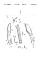
- FIG. 1 is a top perspective view of a vertical stapler according to the present invention
- FIG. 2 is an exploded perspective of the stapler
- FIG. 3 is a side cross-sectional view thereof
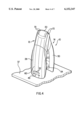
- FIG. 4 is a top perspective view of the stapler standing in a vertical position
- FIG. 5 is a top view thereof
- FIG. 6 is a side view thereof
- FIG. 7 is bottom view thereof
- FIG. 8 is a front end view thereof
- FIG. 9 is a rear end view thereof.
- FIG. 10 cross-sectional view at plane X--X of FIG. 7;
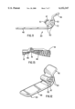
- FIG. 11 is a side view of an idler of the stapler
- FIG. 12 is a perspective of the idler
- FIG. 13 is a cross-sectional view of the stapler open to about 180°.
- vertical stapler 10 has an top pivoting member, preferably a cap 12, and a lower pivoting member, preferably a base 14, pivotably connected to one another with a hinge shaft, which is preferably a pin 16. Also joined by the pin 16 are stapler magazine 18 and the 20, through which the hinge pin 16 is inserted.
- Stapler 10 also has a hammer mechanism 22 with a staple driver 23 positioned between the stapler magazine 18 and the cap 12.
- the magazine 18 is configured for holding a plurality of staples 19 and feeding them, preferably with a spring biased pusher as is known in the art.
- the front portion of the stapler magazine 18 is covered by a nose piece 25.
- the anvil 24 is aligned with the driver 23 and configured for bending legs of the staples 19 driven from the driver 23 against the stack 27.
- a spring 26 disposed between the cap 12 and base 14 assists in returning the cap 12 and stapling mechanism 17 to its normal position by biasing the magazine 18 and the base 14 away from each other.
- the cap 12 and base 14 are constructed of ABS plastic and have a metal U-shaped bracket (not shown) that supports the side walls and hinge points in the stapler's cap 12 and base 14.
- the metal U-shaped bracket is welded inside the cap 12 and base 14, but may also be molded inside the ABS plastic.
- the cap 12 and base 14 have a covering 28, 30 at the location where a user would grip the stapler.
- the coverings 28, 30 are over-molded onto the cap 12 and base 14 and are made of an elastomer and, most preferably, of SantopreneTM.
- the covering 28 on cap 12 also has a staple action location guide 32 to help the user to locate the positioning of the stapling action.
- the guide 32 is a marking, preferably an indentation of the approximate size of the staples 19, preferably within 25%, and more preferably within 15% of the size thereof, for which the stapling mechanism 17 is configured to use, an located substantially directly above the driver 23 and the stapler that is aligned therewith to be stapled into the stack 27.
- the width 49 of the guide 32 is preferably within 25%, and more preferably within 15% of the width of the staples 19.
- End portions 34 and 35 of the cap and base 12 and 14, respectively, located remotely from the pin 16, and preferably at an opposite end of the closed stapler 10 therefrom, are formed as blunt ends which allow the stapler 10 to be stored in a vertical position on a flat, horizontal surface 37, as shown in FIG. 4. Storing the stapler 10 in this position reduces the amount of space taken up on the user's desk or tabletop. Additionally, with the stapler 10 sitting on the ends 34, 35 of the cap 12 and base 14, it is easier for the user to locate, to grab a hold of, and staple papers quickly.
- the blunt ends 34 and 35 preferably are substantially planar or have a curvature with a radius 39 sufficiently large to support the stapler stably on the surface 37, as shown in FIG. 5. Thus, the center of gravity of the stapler is located over the ends 34 and 35 and at a shorter distance from the ends 34 and 35 than the length of the radius 39.
- the base covering 30 on base 14 is sloped downward from the outside edge 36 to a oval-shaped region 38 to a recessed concave area 40 where a user would place their finger tips during actuation of the stapler.
- Area 40 provides a flat stable surface and keeps the stapler 10 well balanced and stable in a horizontal orientation, supporting the stapler 10 on the flat surface during stapling, when the cap 12 is forced against the base 14.
- the base 14 thus has a convex outer surface 52 facing downwardly, which is convex in lateral and longitudinal directions 54 and 56, with a curvature generally conformed to a user's hand, to facilitate grasping of the base during handheld stapling.
- the oval region 40 is a support portion disposed within the convex surface 52 and has a common boundary 58 therewith.
- the recessed portion 40 is sloped upwardly from support portion 38 and is preferably concave in the lateral and longitudinal directions 54 and 56 with a curvature sufficient to receive and stabilize a user's fingers or thumb.
- the oval support portion 38 has a downwardly facing surface disposed generally in a flat plane.
- the oval region 38 is disposed below the driver 23 and below the portion of the cap 12 to which a user will apply the force to bring the cap 12 and base 14 together.
- the oval region 38 is disposed below the center of gravity of the stapler, preferably with and without staples 19, to stably balance the stapler.
- the stapler 10 is also used as a desk-top or table-top stapler in this horizontal position by inserting the pages in the stapling area or space 31 and actuating the stapler by pressing on the cap 12.
- the cap 12 preferably also has a top outer surface 60 facing upwardly and being convex in the longitudinal and lateral directions with a curvature generally conformed to a user's hand.
- the width 78 of the ends 34 and 35 is preferably more than about 50% of the height 80 of the stapler 10, and more preferably greater than about 70 when the stapler is in a normally assumed closed position as shown.
- the inner surfaces 76 of the cap 12 and base 14 are preferably sloped towards the outside edges 36 to facilitate insertion of a stack of paper into the stapling space. This is particularly useful when the stapler is held by hand.
- the stapler 10 also has, as shown in FIGS. 11 and 12, a hinge cover or idler 20 having a hole 47 through which the hinge pin 16 is inserted.
- the idler 20 is preferably made from a molded plastic and most preferably polypropylene to allow for easy deformation of the idler 20 as the stapler opens and closes.
- the idler 20 also functions to hide the hinge pin 16.
- Top tab 46 of idler 20 is inserted into the cap 12 of the stapler and lodges against the underside of cap 12, providing an interference or frictional fit.
- the bottom tab portion 48 is inserted into the base 14 of the stapler 10.
- the flat bottom tab portion 48 is allowed to move freely in and out of the base 14, preferably sliding along the inside, top surface of the base 14 when the stapler 10 is opened and closed.
- the idler 20 of FIGS. 11 and 12 have ribs 50 that extend from a cylindrical, central, tube portion 70, the hole 47 of which rotatably receives the pin 16, support the outer surface of the idler 20 and also are deformable to allow deformation of the idler 20 as the stapler 10 is opened and closed.
- the configuration of the idler 20, along with the cap 12 and base 14 of the stapler 10, allow the stapler to be opened to approximately 180° to allow for a tacking function, as shown in FIG. 13.
- the tabs 46 and 48 have a normally assumed position shown in FIGS. 11 and 12 selected such that they bent inwardly by the base and cap to ensure proper positioning in the open stapler position of FIG. 10. Since the idler 20 is made of polypropylene, the opening and closing of the stapler does not cause undue stress on the idler 20. Instead of a plurality of ribs, the idler 20 of FIG. 3 has only a single wide rib.
- the ribs are disposed around the tube 70 over an angle 72 of preferably around 90° or less, and more preferably of about 100°. This allows the tabs 46 and 48 to bend more easily from adjacent the nearest rib 50.
- the idler 20 is preferably of unitary construction, and covers the area between clevis arms 74 of the cap 12 and base 14, which are preferably closed to conceal the pin 16 and the pivot area of the stapler 10.
Abstract
Description
Claims (20)
Priority Applications (1)
| Application Number | Priority Date | Filing Date | Title |
|---|---|---|---|
| US09/239,808 US6152347A (en) | 1998-01-30 | 1999-01-29 | Vertical Stapler |
Applications Claiming Priority (2)
| Application Number | Priority Date | Filing Date | Title |
|---|---|---|---|
| US7316398P | 1998-01-30 | 1998-01-30 | |
| US09/239,808 US6152347A (en) | 1998-01-30 | 1999-01-29 | Vertical Stapler |
Publications (1)
| Publication Number | Publication Date |
|---|---|
| US6152347A true US6152347A (en) | 2000-11-28 |
Family
ID=22112104
Family Applications (1)
| Application Number | Title | Priority Date | Filing Date |
|---|---|---|---|
| US09/239,808 Expired - Lifetime US6152347A (en) | 1998-01-30 | 1999-01-29 | Vertical Stapler |
Country Status (2)
| Country | Link |
|---|---|
| US (1) | US6152347A (en) |
| WO (1) | WO1999038654A1 (en) |
Cited By (39)
| Publication number | Priority date | Publication date | Assignee | Title |
|---|---|---|---|---|
| US6338430B1 (en) * | 2001-07-09 | 2002-01-15 | Chiu-Ju Cheng | Decorative housing for a stapler |
| US6386418B1 (en) * | 2000-07-31 | 2002-05-14 | Nancy T. Garner | Palm stapler |
| US6471108B1 (en) * | 2001-11-27 | 2002-10-29 | Green Lake Enterprise Co., Ltd. | Audio and video effect stapler |
| US20030047581A1 (en) * | 2001-03-05 | 2003-03-13 | Shigekazu Tanaka | Stapler |
| EP1304192A1 (en) * | 2001-10-16 | 2003-04-23 | BALMA, CAPODURI & C. S.p.A. | Improved stapler construction |
| US6601747B1 (en) * | 2003-02-13 | 2003-08-05 | Su-Chao Chi Kuo | Office tool assembly |
| WO2004103648A2 (en) * | 2003-05-23 | 2004-12-02 | Worktools, Inc. | Spring energized desktop stapler |
| US20040262019A1 (en) * | 2000-11-28 | 2004-12-30 | Hubbard Melvin L | Method and apparatus for vibratory kinetic energy generation and applications thereof |
| US6883697B1 (en) | 2004-02-23 | 2005-04-26 | Apex Mfg. Co., Ltd. | Office tool assembly |
| US20050098604A1 (en) * | 2003-11-10 | 2005-05-12 | Marks Joel S. | Spring energized desktop stapler |
| US20050173488A1 (en) * | 2002-05-28 | 2005-08-11 | Yoshiyuki Ebihara | Cassette for stapler |
| US20050224554A1 (en) * | 2004-04-02 | 2005-10-13 | Acco Brands, Inc. | Stapler with device for holding stapler open |
| US20060144895A1 (en) * | 2004-04-02 | 2006-07-06 | Acco Brands, Inc. | Stapler with improved base and cover construction |
| US20060144894A1 (en) * | 2004-04-02 | 2006-07-06 | Acco Brands, Inc. | Stapler with improved base construction |
| US20060151566A1 (en) * | 2002-05-28 | 2006-07-13 | Yoshiyuki Ebihara | Cassette type stapler |
| US20060186170A1 (en) * | 2005-02-23 | 2006-08-24 | Marks Joel S | Stapler safety device to limit motion of striker |
| EP1707320A1 (en) * | 2005-03-31 | 2006-10-04 | Cotapaxi Custom Design and Manufacturing, LLC | Combination stapler with tape dispenser |
| US7124924B2 (en) | 2004-11-17 | 2006-10-24 | Worktools, Inc. | Desktop stapler striker/anvil alignment system |
| US20060289598A1 (en) * | 2005-06-22 | 2006-12-28 | Ching-Tsung Tsai | Stapler provided with an article accommodating space |
| KR100706041B1 (en) * | 2000-07-27 | 2007-04-11 | 쟈인 에레쿠토로닉스 가부시키가이샤 | Multiphase clock generating circuit |
| US20070084983A1 (en) * | 2004-02-19 | 2007-04-19 | Dilip Bhavnani | Mirrored document holder |
| US7216791B1 (en) | 2005-01-21 | 2007-05-15 | Worktools, Inc. | Spring energized stapler lever fulcrum in low position |
| US20070108251A1 (en) * | 2005-02-23 | 2007-05-17 | Worktools, Inc. | Stapler safety device to limit motion of striker |
| US20070124866A1 (en) * | 2005-12-06 | 2007-06-07 | Ryan Grepper | Vertically standing stapler and tape dispensing device |
| US20070251968A1 (en) * | 2006-04-27 | 2007-11-01 | Elmer's Products, Inc. | Mini-stapler with elastic band |
| US20070251974A1 (en) * | 2006-04-27 | 2007-11-01 | Elmer's Products, Inc. | Ergonomic hand-held stapler |
| US7299960B1 (en) | 2006-12-20 | 2007-11-27 | Worktools, Inc. | Mini desktop stapler |
| US20080011808A1 (en) * | 2003-05-23 | 2008-01-17 | Accentra, Inc. | Staple guide track |
| US20080128467A1 (en) * | 2006-12-01 | 2008-06-05 | Dilip Bhavnani | Stapler for advertising |
| JP2008155356A (en) * | 2006-11-29 | 2008-07-10 | Max Co Ltd | Stapler |
| US20080302853A1 (en) * | 2005-02-24 | 2008-12-11 | Joel Marks | Contoured base for desktop stapler |
| US20090050669A1 (en) * | 2007-08-21 | 2009-02-26 | William Carlton Zolentroff | MID-ZONE STAPLER or PRESSING TOOL |
| JP2009061538A (en) * | 2007-09-05 | 2009-03-26 | Max Co Ltd | Stapler |
| US20100032469A1 (en) * | 2008-07-01 | 2010-02-11 | Jeff Baker | Stapler with integrated paper clip holder |
| US20100243701A1 (en) * | 2006-10-31 | 2010-09-30 | Bin Yu | Lever Stapler |
| US20110049214A1 (en) * | 2009-09-01 | 2011-03-03 | Cosimex (H.K.) Limited | Light weight hand-operated stapler |
| US20120037684A1 (en) * | 2009-12-16 | 2012-02-16 | Worktools, Inc. | Leveraged action stapler |
| US10932781B2 (en) * | 2018-02-06 | 2021-03-02 | Ethicon Llc | Features to align and close linear surgical stapler |
| US11278285B2 (en) * | 2018-08-13 | 2022-03-22 | Cilag GbmH International | Clamping assembly for linear surgical stapler |
Families Citing this family (1)
| Publication number | Priority date | Publication date | Assignee | Title |
|---|---|---|---|---|
| EP3406249A1 (en) | 2001-02-19 | 2018-11-28 | Novartis AG | Treatment of breast tumors with a rapamycin derivative in combination with an aromatase inhibitor |
Citations (24)
| Publication number | Priority date | Publication date | Assignee | Title |
|---|---|---|---|---|
| US2240911A (en) * | 1939-05-01 | 1941-05-06 | Hotchkiss Co E H | Staple driving machine |
| US2251915A (en) * | 1938-04-26 | 1941-08-12 | Speed Products Company | Stapling pliers |
| US2269744A (en) * | 1940-08-20 | 1942-01-13 | American Die & Tool Corp | Stapling device |
| US2381192A (en) * | 1938-07-09 | 1945-08-07 | Vancura Rudolf | Stapling device |
| US2399761A (en) * | 1940-01-15 | 1946-05-07 | Metal Specialties Mfg Co | Stapler |
| US2511944A (en) * | 1950-06-20 | Apparatus for securing together | ||
| US2604623A (en) * | 1948-12-30 | 1952-07-29 | Speed Products Co Inc | Pocket stapling machine |
| US2658197A (en) * | 1950-06-05 | 1953-11-10 | William G Pankonin | Stapling machine |
| US2920324A (en) * | 1958-09-11 | 1960-01-12 | Bostitch Inc | Fastener applying machine |
| US3083367A (en) * | 1960-02-08 | 1963-04-02 | Ace Fastener Corp | Stapling device |
| US3640443A (en) * | 1968-12-26 | 1972-02-08 | Max Corp | Stapler |
| US3987951A (en) * | 1975-11-05 | 1976-10-26 | Gail M. Thornhill | Upright stapler |
| US4014493A (en) * | 1974-07-29 | 1977-03-29 | Prodev Limited | Housing for a stapler |
| US4607777A (en) * | 1984-07-06 | 1986-08-26 | Etona Company, Limited | Stapler |
| US4666075A (en) * | 1985-11-18 | 1987-05-19 | Swingline Inc. | Stapler mechanism |
| US4706866A (en) * | 1985-11-21 | 1987-11-17 | Etona Company, Limited | Stapler |
| US4706865A (en) * | 1985-11-14 | 1987-11-17 | Etona Company, Limited | Stapler |
| US4717062A (en) * | 1985-09-20 | 1988-01-05 | Yoshiyuki Ebihara | Stapler |
| US4756462A (en) * | 1985-10-17 | 1988-07-12 | Etona Company Limited | Cassette type stapler |
| US4784307A (en) * | 1986-09-26 | 1988-11-15 | Yoshiyuki Ebihara | Cassette type stapler |
| US4878608A (en) * | 1988-07-13 | 1989-11-07 | M.G.S. Japan Co., Ltd. | Hand stapler for use with a bar of ornamented staples |
| US4925082A (en) * | 1988-07-06 | 1990-05-15 | Kim Kwang Shick | Stapler with indicator windows |
| US4949893A (en) * | 1989-08-18 | 1990-08-21 | Heckathorn Carolann M | Emergency staple pack |
| US5797535A (en) * | 1997-05-14 | 1998-08-25 | Acco Usa, Inc. | Stapler with storage compartment and cover slipper |
-
1999
- 1999-01-29 US US09/239,808 patent/US6152347A/en not_active Expired - Lifetime
- 1999-02-01 WO PCT/US1999/002088 patent/WO1999038654A1/en active Application Filing
Patent Citations (24)
| Publication number | Priority date | Publication date | Assignee | Title |
|---|---|---|---|---|
| US2511944A (en) * | 1950-06-20 | Apparatus for securing together | ||
| US2251915A (en) * | 1938-04-26 | 1941-08-12 | Speed Products Company | Stapling pliers |
| US2381192A (en) * | 1938-07-09 | 1945-08-07 | Vancura Rudolf | Stapling device |
| US2240911A (en) * | 1939-05-01 | 1941-05-06 | Hotchkiss Co E H | Staple driving machine |
| US2399761A (en) * | 1940-01-15 | 1946-05-07 | Metal Specialties Mfg Co | Stapler |
| US2269744A (en) * | 1940-08-20 | 1942-01-13 | American Die & Tool Corp | Stapling device |
| US2604623A (en) * | 1948-12-30 | 1952-07-29 | Speed Products Co Inc | Pocket stapling machine |
| US2658197A (en) * | 1950-06-05 | 1953-11-10 | William G Pankonin | Stapling machine |
| US2920324A (en) * | 1958-09-11 | 1960-01-12 | Bostitch Inc | Fastener applying machine |
| US3083367A (en) * | 1960-02-08 | 1963-04-02 | Ace Fastener Corp | Stapling device |
| US3640443A (en) * | 1968-12-26 | 1972-02-08 | Max Corp | Stapler |
| US4014493A (en) * | 1974-07-29 | 1977-03-29 | Prodev Limited | Housing for a stapler |
| US3987951A (en) * | 1975-11-05 | 1976-10-26 | Gail M. Thornhill | Upright stapler |
| US4607777A (en) * | 1984-07-06 | 1986-08-26 | Etona Company, Limited | Stapler |
| US4717062A (en) * | 1985-09-20 | 1988-01-05 | Yoshiyuki Ebihara | Stapler |
| US4756462A (en) * | 1985-10-17 | 1988-07-12 | Etona Company Limited | Cassette type stapler |
| US4706865A (en) * | 1985-11-14 | 1987-11-17 | Etona Company, Limited | Stapler |
| US4666075A (en) * | 1985-11-18 | 1987-05-19 | Swingline Inc. | Stapler mechanism |
| US4706866A (en) * | 1985-11-21 | 1987-11-17 | Etona Company, Limited | Stapler |
| US4784307A (en) * | 1986-09-26 | 1988-11-15 | Yoshiyuki Ebihara | Cassette type stapler |
| US4925082A (en) * | 1988-07-06 | 1990-05-15 | Kim Kwang Shick | Stapler with indicator windows |
| US4878608A (en) * | 1988-07-13 | 1989-11-07 | M.G.S. Japan Co., Ltd. | Hand stapler for use with a bar of ornamented staples |
| US4949893A (en) * | 1989-08-18 | 1990-08-21 | Heckathorn Carolann M | Emergency staple pack |
| US5797535A (en) * | 1997-05-14 | 1998-08-25 | Acco Usa, Inc. | Stapler with storage compartment and cover slipper |
Cited By (71)
| Publication number | Priority date | Publication date | Assignee | Title |
|---|---|---|---|---|
| KR100706041B1 (en) * | 2000-07-27 | 2007-04-11 | 쟈인 에레쿠토로닉스 가부시키가이샤 | Multiphase clock generating circuit |
| US6386418B1 (en) * | 2000-07-31 | 2002-05-14 | Nancy T. Garner | Palm stapler |
| US20040262019A1 (en) * | 2000-11-28 | 2004-12-30 | Hubbard Melvin L | Method and apparatus for vibratory kinetic energy generation and applications thereof |
| US20030047581A1 (en) * | 2001-03-05 | 2003-03-13 | Shigekazu Tanaka | Stapler |
| US6966479B2 (en) * | 2001-03-05 | 2005-11-22 | Kokuyo Co., Ltd. | Stapler |
| US6338430B1 (en) * | 2001-07-09 | 2002-01-15 | Chiu-Ju Cheng | Decorative housing for a stapler |
| EP1304192A1 (en) * | 2001-10-16 | 2003-04-23 | BALMA, CAPODURI & C. S.p.A. | Improved stapler construction |
| US20030085251A1 (en) * | 2001-10-16 | 2003-05-08 | Giorgio Balma | Stapler construction |
| US6761300B2 (en) * | 2001-10-16 | 2004-07-13 | Giorgio Balma | Stapler construction |
| US6471108B1 (en) * | 2001-11-27 | 2002-10-29 | Green Lake Enterprise Co., Ltd. | Audio and video effect stapler |
| US20050173488A1 (en) * | 2002-05-28 | 2005-08-11 | Yoshiyuki Ebihara | Cassette for stapler |
| US20060151566A1 (en) * | 2002-05-28 | 2006-07-13 | Yoshiyuki Ebihara | Cassette type stapler |
| US7066370B2 (en) * | 2002-05-28 | 2006-06-27 | E-Top Corporation | Cassette for stapler |
| US6601747B1 (en) * | 2003-02-13 | 2003-08-05 | Su-Chao Chi Kuo | Office tool assembly |
| US7178709B2 (en) | 2003-05-23 | 2007-02-20 | Worktools, Inc. | Spring energized desktop stapler |
| US7648054B2 (en) | 2003-05-23 | 2010-01-19 | Worktools, Inc. | Spring energized desktop stapler |
| US20050139631A1 (en) * | 2003-05-23 | 2005-06-30 | Joel Marks | Spring energized desktop stapler |
| GB2416323A (en) * | 2003-05-23 | 2006-01-25 | Worktools Inc | Spring energized desktop stapler |
| GB2416323B (en) * | 2003-05-23 | 2007-02-21 | Worktools Inc | Desktop stapler |
| US7503472B2 (en) * | 2003-05-23 | 2009-03-17 | Worktools, Inc. | Spring energized desktop stapler |
| US20080011808A1 (en) * | 2003-05-23 | 2008-01-17 | Accentra, Inc. | Staple guide track |
| WO2004103648A2 (en) * | 2003-05-23 | 2004-12-02 | Worktools, Inc. | Spring energized desktop stapler |
| US20070125823A1 (en) * | 2003-05-23 | 2007-06-07 | Joel Marks | Spring energized desktop stapler |
| WO2004103648A3 (en) * | 2003-05-23 | 2005-03-17 | Worktools Inc | Spring energized desktop stapler |
| US7748589B2 (en) | 2003-05-23 | 2010-07-06 | Worktools, Inc. | Spring energized desktop stapler |
| US7407072B2 (en) * | 2003-05-23 | 2008-08-05 | Worktools, Inc. | Contoured base for desktop stapler |
| US20060213948A1 (en) * | 2003-05-23 | 2006-09-28 | Joel Marks | Spring energized desktop stapler |
| US20060213949A1 (en) * | 2003-05-23 | 2006-09-28 | Joel Marks | Contoured base for desktop stapler |
| US20060213950A1 (en) * | 2003-11-10 | 2006-09-28 | Marks Joel S | Spring energized desktop stapler |
| US7080768B2 (en) | 2003-11-10 | 2006-07-25 | Worktools, Inc. | Spring energized desktop stapler |
| US20050098604A1 (en) * | 2003-11-10 | 2005-05-12 | Marks Joel S. | Spring energized desktop stapler |
| US20070084983A1 (en) * | 2004-02-19 | 2007-04-19 | Dilip Bhavnani | Mirrored document holder |
| US6883697B1 (en) | 2004-02-23 | 2005-04-26 | Apex Mfg. Co., Ltd. | Office tool assembly |
| US20050224554A1 (en) * | 2004-04-02 | 2005-10-13 | Acco Brands, Inc. | Stapler with device for holding stapler open |
| US20060144894A1 (en) * | 2004-04-02 | 2006-07-06 | Acco Brands, Inc. | Stapler with improved base construction |
| US20060144895A1 (en) * | 2004-04-02 | 2006-07-06 | Acco Brands, Inc. | Stapler with improved base and cover construction |
| US7549561B2 (en) | 2004-04-02 | 2009-06-23 | Acco Brands Usa Llc | Stapler with improved base construction |
| US7124924B2 (en) | 2004-11-17 | 2006-10-24 | Worktools, Inc. | Desktop stapler striker/anvil alignment system |
| US7216791B1 (en) | 2005-01-21 | 2007-05-15 | Worktools, Inc. | Spring energized stapler lever fulcrum in low position |
| US20070108251A1 (en) * | 2005-02-23 | 2007-05-17 | Worktools, Inc. | Stapler safety device to limit motion of striker |
| US7234621B2 (en) | 2005-02-23 | 2007-06-26 | Worktools, Inc. | Stapler safety device to limit motion of striker |
| US20060186169A1 (en) * | 2005-02-23 | 2006-08-24 | Marks Joel S | Stapler safety guard |
| US7290692B2 (en) | 2005-02-23 | 2007-11-06 | Worktools, Inc. | Stapler safety device to limit motion of striker |
| US20060186170A1 (en) * | 2005-02-23 | 2006-08-24 | Marks Joel S | Stapler safety device to limit motion of striker |
| US7124922B2 (en) | 2005-02-23 | 2006-10-24 | Worktools, Inc. | Stapler safety guard |
| US20080302853A1 (en) * | 2005-02-24 | 2008-12-11 | Joel Marks | Contoured base for desktop stapler |
| US20060218826A1 (en) * | 2005-03-31 | 2006-10-05 | Carl Cetera | Tapeler1 |
| EP1707320A1 (en) * | 2005-03-31 | 2006-10-04 | Cotapaxi Custom Design and Manufacturing, LLC | Combination stapler with tape dispenser |
| US7373682B2 (en) * | 2005-03-31 | 2008-05-20 | Cotapaxi Custom Design And Manufacturing, Llc | Tapeler |
| US20060289598A1 (en) * | 2005-06-22 | 2006-12-28 | Ching-Tsung Tsai | Stapler provided with an article accommodating space |
| US20070124866A1 (en) * | 2005-12-06 | 2007-06-07 | Ryan Grepper | Vertically standing stapler and tape dispensing device |
| US20070251968A1 (en) * | 2006-04-27 | 2007-11-01 | Elmer's Products, Inc. | Mini-stapler with elastic band |
| US20070251974A1 (en) * | 2006-04-27 | 2007-11-01 | Elmer's Products, Inc. | Ergonomic hand-held stapler |
| US20100243701A1 (en) * | 2006-10-31 | 2010-09-30 | Bin Yu | Lever Stapler |
| JP2008155356A (en) * | 2006-11-29 | 2008-07-10 | Max Co Ltd | Stapler |
| US20080128467A1 (en) * | 2006-12-01 | 2008-06-05 | Dilip Bhavnani | Stapler for advertising |
| US20080149683A1 (en) * | 2006-12-20 | 2008-06-26 | Worktools, Inc. | Mini desktop stapler |
| US7513406B2 (en) | 2006-12-20 | 2009-04-07 | Worktools, Inc. | Mini desktop stapler |
| US20090134197A1 (en) * | 2006-12-20 | 2009-05-28 | Worktools, Inc. | Mini desktop stapler |
| US7299960B1 (en) | 2006-12-20 | 2007-11-27 | Worktools, Inc. | Mini desktop stapler |
| US7828184B2 (en) | 2006-12-20 | 2010-11-09 | Worktools, Inc. | Mini desktop stapler |
| US7963429B2 (en) | 2007-08-21 | 2011-06-21 | William Carlton Zolentroff | Mid-zone stapler or pressing tool |
| US20090050669A1 (en) * | 2007-08-21 | 2009-02-26 | William Carlton Zolentroff | MID-ZONE STAPLER or PRESSING TOOL |
| JP2009061538A (en) * | 2007-09-05 | 2009-03-26 | Max Co Ltd | Stapler |
| US20100032469A1 (en) * | 2008-07-01 | 2010-02-11 | Jeff Baker | Stapler with integrated paper clip holder |
| US20110049214A1 (en) * | 2009-09-01 | 2011-03-03 | Cosimex (H.K.) Limited | Light weight hand-operated stapler |
| US8052023B2 (en) * | 2009-09-01 | 2011-11-08 | Cosimex (H.K.) Limited | Light weight hand-operated stapler |
| US20120037684A1 (en) * | 2009-12-16 | 2012-02-16 | Worktools, Inc. | Leveraged action stapler |
| US8348117B2 (en) * | 2009-12-16 | 2013-01-08 | Worktools, Inc. | Leveraged action stapler |
| US10932781B2 (en) * | 2018-02-06 | 2021-03-02 | Ethicon Llc | Features to align and close linear surgical stapler |
| US11278285B2 (en) * | 2018-08-13 | 2022-03-22 | Cilag GbmH International | Clamping assembly for linear surgical stapler |
Also Published As
| Publication number | Publication date |
|---|---|
| WO1999038654A1 (en) | 1999-08-05 |
Similar Documents
| Publication | Publication Date | Title |
|---|---|---|
| US6152347A (en) | Vertical Stapler | |
| US7290694B2 (en) | Stapler with detachable accessory | |
| US6349868B1 (en) | Multipurpose stapler | |
| ES2534329T3 (en) | Desktop mini stapler | |
| US6779425B2 (en) | Multipurpose handheld implement | |
| US20110233256A1 (en) | Spring actuated pliers stapler | |
| US20110132953A1 (en) | Hammer holder | |
| US20060075639A1 (en) | Nail clipper | |
| US5797535A (en) | Stapler with storage compartment and cover slipper | |
| GB2429424A (en) | A stapler with pivoting guide for use in stapling electrical wires | |
| US2726393A (en) | Storage compartment for staples on a stapling machine | |
| US20060144894A1 (en) | Stapler with improved base construction | |
| US6062456A (en) | Staple extractor and stapler combination | |
| US5632188A (en) | Ergopunch | |
| JPH0616667Y2 (en) | Stepper | |
| US7222427B1 (en) | Nail clipper | |
| US6470536B1 (en) | Clip board with improved retention means | |
| US20070124866A1 (en) | Vertically standing stapler and tape dispensing device | |
| US4905832A (en) | Packaging for the display and handling of small objects | |
| JP4158682B2 (en) | Stapler | |
| US4187971A (en) | Stapler for an improved flexible pusher retracting member | |
| JP5056132B2 (en) | Stapler | |
| CN210361175U (en) | Novel stapler capable of simultaneously binding multiple nails | |
| US4969590A (en) | Top-loading stapler | |
| JPH08112781A (en) | Stapler |
Legal Events
| Date | Code | Title | Description |
|---|---|---|---|
| AS | Assignment |
Owner name: ACCO BRANDS, INC., ILLINOIS Free format text: ASSIGNMENT OF ASSIGNORS INTEREST;ASSIGNORS:WILSON, SCOTT H.;KAPUR, SUMIR;BERRY, STEPHEN D.;AND OTHERS;REEL/FRAME:009815/0143 Effective date: 19990304 |
|
| STCF | Information on status: patent grant |
Free format text: PATENTED CASE |
|
| FEPP | Fee payment procedure |
Free format text: PAYOR NUMBER ASSIGNED (ORIGINAL EVENT CODE: ASPN); ENTITY STATUS OF PATENT OWNER: LARGE ENTITY |
|
| FPAY | Fee payment |
Year of fee payment: 4 |
|
| AS | Assignment |
Owner name: CITICORP NORTH AMERICA, AS ADMINISTRATIVE AGENT, I Free format text: PATENT SECURITY AGREEMENT;ASSIGNORS:ACCO BRANDS CORPORATION, A DELAWARE CORPORATION;ACCO BRANDS USA LLC, A DELAWARE LIMITED LIABILITY COMPANY BOONE INTERNATIONAL, INC., A CALIFORNIA CORPORATION GENERAL BINDING CORPORATION, A DELAWARE CORPORATION;BOONE INTERNATIONAL, INC., A CALIFORNIA CORPORATION;AND OTHERS;REEL/FRAME:016914/0813 Effective date: 20050817 |
|
| AS | Assignment |
Owner name: ACCO BRANDS USA LLC, ILLINOIS Free format text: CHANGE OF NAME;ASSIGNOR:ACCO BRANDS, INC.;REEL/FRAME:016674/0785 Effective date: 20050802 |
|
| FPAY | Fee payment |
Year of fee payment: 8 |
|
| AS | Assignment |
Owner name: ACCO BRANDS CORPORATION, ILLINOIS Free format text: RELEASE BY SECURED PARTY;ASSIGNOR:CITICORP NORTH AMERICA, INC.;REEL/FRAME:023312/0784 Effective date: 20090930 Owner name: ACCO BRANDS USA LLC, ILLINOIS Free format text: RELEASE BY SECURED PARTY;ASSIGNOR:CITICORP NORTH AMERICA, INC.;REEL/FRAME:023312/0784 Effective date: 20090930 Owner name: BOONE INTERNATIONAL, INC., ILLINOIS Free format text: RELEASE BY SECURED PARTY;ASSIGNOR:CITICORP NORTH AMERICA, INC.;REEL/FRAME:023312/0784 Effective date: 20090930 Owner name: GENERAL BINDING CORPORATION, ILLINOIS Free format text: RELEASE BY SECURED PARTY;ASSIGNOR:CITICORP NORTH AMERICA, INC.;REEL/FRAME:023312/0784 Effective date: 20090930 Owner name: U.S. BANK NATIONAL ASSOCIATION, ILLINOIS Free format text: SECURITY AGREEMENT;ASSIGNORS:ACCO BRANDS CORPORATION;ACCO BRANDS USA LLC;DAY-TIMERS INC.;AND OTHERS;REEL/FRAME:023312/0902 Effective date: 20090930 Owner name: ACCO BRANDS CORPORATION,ILLINOIS Free format text: RELEASE BY SECURED PARTY;ASSIGNOR:CITICORP NORTH AMERICA, INC.;REEL/FRAME:023312/0784 Effective date: 20090930 Owner name: ACCO BRANDS USA LLC,ILLINOIS Free format text: RELEASE BY SECURED PARTY;ASSIGNOR:CITICORP NORTH AMERICA, INC.;REEL/FRAME:023312/0784 Effective date: 20090930 Owner name: BOONE INTERNATIONAL, INC.,ILLINOIS Free format text: RELEASE BY SECURED PARTY;ASSIGNOR:CITICORP NORTH AMERICA, INC.;REEL/FRAME:023312/0784 Effective date: 20090930 Owner name: GENERAL BINDING CORPORATION,ILLINOIS Free format text: RELEASE BY SECURED PARTY;ASSIGNOR:CITICORP NORTH AMERICA, INC.;REEL/FRAME:023312/0784 Effective date: 20090930 Owner name: U.S. BANK NATIONAL ASSOCIATION,ILLINOIS Free format text: SECURITY AGREEMENT;ASSIGNORS:ACCO BRANDS CORPORATION;ACCO BRANDS USA LLC;DAY-TIMERS INC.;AND OTHERS;REEL/FRAME:023312/0902 Effective date: 20090930 |
|
| AS | Assignment |
Owner name: DEUTSCHE BANK AG NEW YORK BRANCH, NEW YORK Free format text: SECURITY AGREEMENT;ASSIGNORS:ACCO BRANDS CORPORATION;ACCO BRANDS USA LLC;DAY-TIMERS INC.;AND OTHERS;REEL/FRAME:023449/0180 Effective date: 20090930 Owner name: DEUTSCHE BANK AG NEW YORK BRANCH,NEW YORK Free format text: SECURITY AGREEMENT;ASSIGNORS:ACCO BRANDS CORPORATION;ACCO BRANDS USA LLC;DAY-TIMERS INC.;AND OTHERS;REEL/FRAME:023449/0180 Effective date: 20090930 |
|
| FPAY | Fee payment |
Year of fee payment: 12 |
|
| AS | Assignment |
Owner name: ACCO BRANDS CORPORATION, ILLINOIS Free format text: RELEASE BY SECURED PARTY;ASSIGNOR:U.S. BANK NATIONAL ASSOCIATION, AS COLLATERAL TRUSTEE;REEL/FRAME:028168/0713 Effective date: 20120430 Owner name: ACCO BRANDS CORPORATION, ILLINOIS Free format text: RELEASE BY SECURED PARTY;ASSIGNOR:DEUTSCHE BANK AG NEW YORK BRANCH, AS COLLATERAL AGENT;REEL/FRAME:028168/0738 Effective date: 20120430 |
|
| AS | Assignment |
Owner name: BARCLAYS BANK PLC, AS ADMINISTRATIVE AGENT, NEW YO Free format text: SECURITY AGREEMENT;ASSIGNOR:ACCO BRANDS USA LLC;REEL/FRAME:028217/0360 Effective date: 20120430 |
|
| AS | Assignment |
Owner name: ACCO BRANDS CORPORATION, ILLINOIS Free format text: CORRECTIVE ASSIGNMENT TO CORRECT THE THE MISSING ASSIGNEES ON THE RELEASE OF SECURITY INTEREST IN PATENTS PREVIOUSLY RECORDED ON REEL 028168 FRAME 0713. ASSIGNOR(S) HEREBY CONFIRMS THE ASSIGNEES ACCO BRANDS USA LLC AND GENERAL BINDING CORPORATION ARE ADDITIONAL ASSIGNEES;ASSIGNOR:U.S. BANK NATIONAL ASSOCIATION, AS COLLATERAL TRUSTEE;REEL/FRAME:028487/0671 Effective date: 20120430 Owner name: ACCO BRANDS CORPORATION, ILLINOIS Free format text: CORRECTIVE ASSIGNMENT TO CORRECT THE MISSING ASSIGNEES ON THE RELEASE OF SECURITY INTEREST IN PATENTS PREVIOUSLY RECORDED ON REEL 028168 FRAME 0738. ASSIGNOR(S) HEREBY CONFIRMS THE ASSIGNEES ACCO BRANDS USA LLC, AND GENERAL BINDING CORPORATION ARE ADDITIONAL ASIGNEES;ASSIGNOR:DEUTSCHE BANK AG NEW YORK BRANK, AS COLLATERAL AGENT;REEL/FRAME:028488/0056 Effective date: 20120430 Owner name: GENERAL BINDING CORPORATION, ILLINOIS Free format text: CORRECTIVE ASSIGNMENT TO CORRECT THE THE MISSING ASSIGNEES ON THE RELEASE OF SECURITY INTEREST IN PATENTS PREVIOUSLY RECORDED ON REEL 028168 FRAME 0713. ASSIGNOR(S) HEREBY CONFIRMS THE ASSIGNEES ACCO BRANDS USA LLC AND GENERAL BINDING CORPORATION ARE ADDITIONAL ASSIGNEES;ASSIGNOR:U.S. BANK NATIONAL ASSOCIATION, AS COLLATERAL TRUSTEE;REEL/FRAME:028487/0671 Effective date: 20120430 Owner name: GENERAL BINDING CORPORATION, ILLINOIS Free format text: CORRECTIVE ASSIGNMENT TO CORRECT THE MISSING ASSIGNEES ON THE RELEASE OF SECURITY INTEREST IN PATENTS PREVIOUSLY RECORDED ON REEL 028168 FRAME 0738. ASSIGNOR(S) HEREBY CONFIRMS THE ASSIGNEES ACCO BRANDS USA LLC, AND GENERAL BINDING CORPORATION ARE ADDITIONAL ASIGNEES;ASSIGNOR:DEUTSCHE BANK AG NEW YORK BRANK, AS COLLATERAL AGENT;REEL/FRAME:028488/0056 Effective date: 20120430 Owner name: ACCO BRANDS USA LLC, ILLINOIS Free format text: CORRECTIVE ASSIGNMENT TO CORRECT THE MISSING ASSIGNEES ON THE RELEASE OF SECURITY INTEREST IN PATENTS PREVIOUSLY RECORDED ON REEL 028168 FRAME 0738. ASSIGNOR(S) HEREBY CONFIRMS THE ASSIGNEES ACCO BRANDS USA LLC, AND GENERAL BINDING CORPORATION ARE ADDITIONAL ASIGNEES;ASSIGNOR:DEUTSCHE BANK AG NEW YORK BRANK, AS COLLATERAL AGENT;REEL/FRAME:028488/0056 Effective date: 20120430 Owner name: ACCO BRANDS USA LLC, ILLINOIS Free format text: CORRECTIVE ASSIGNMENT TO CORRECT THE THE MISSING ASSIGNEES ON THE RELEASE OF SECURITY INTEREST IN PATENTS PREVIOUSLY RECORDED ON REEL 028168 FRAME 0713. ASSIGNOR(S) HEREBY CONFIRMS THE ASSIGNEES ACCO BRANDS USA LLC AND GENERAL BINDING CORPORATION ARE ADDITIONAL ASSIGNEES;ASSIGNOR:U.S. BANK NATIONAL ASSOCIATION, AS COLLATERAL TRUSTEE;REEL/FRAME:028487/0671 Effective date: 20120430 |
|
| AS | Assignment |
Owner name: BANK OF AMERICA, N.A., AS NEW ADMINISTRATIVE AGENT Free format text: ASSIGNMENT AND ASSUMPTION OF INTELLECTUAL PROPERTY SECURITY AGREEMENT RECORDED AT R/F 028217/0360;ASSIGNOR:BARCLAYS BANK PLC, AS EXISTING ADMINISTRATIVE AGENT, EXISTING SWING LINE LENDER AND EXISTING L/C ISSUER;REEL/FRAME:030427/0574 Effective date: 20130513 |