US6151580A - Audio playback apparatus - Google Patents
Audio playback apparatus Download PDFInfo
- Publication number
- US6151580A US6151580A US09/251,502 US25150299A US6151580A US 6151580 A US6151580 A US 6151580A US 25150299 A US25150299 A US 25150299A US 6151580 A US6151580 A US 6151580A
- Authority
- US
- United States
- Prior art keywords
- data
- decoder
- audio
- playback apparatus
- data stream
- Prior art date
- Legal status (The legal status is an assumption and is not a legal conclusion. Google has not performed a legal analysis and makes no representation as to the accuracy of the status listed.)
- Expired - Lifetime
Links
Images
Classifications
-
- G—PHYSICS
- G11—INFORMATION STORAGE
- G11B—INFORMATION STORAGE BASED ON RELATIVE MOVEMENT BETWEEN RECORD CARRIER AND TRANSDUCER
- G11B20/00—Signal processing not specific to the method of recording or reproducing; Circuits therefor
- G11B20/10—Digital recording or reproducing
- G11B20/10527—Audio or video recording; Data buffering arrangements
-
- G—PHYSICS
- G11—INFORMATION STORAGE
- G11B—INFORMATION STORAGE BASED ON RELATIVE MOVEMENT BETWEEN RECORD CARRIER AND TRANSDUCER
- G11B19/00—Driving, starting, stopping record carriers not specifically of filamentary or web form, or of supports therefor; Control thereof; Control of operating function ; Driving both disc and head
- G11B19/20—Driving; Starting; Stopping; Control thereof
- G11B19/28—Speed controlling, regulating, or indicating
-
- G—PHYSICS
- G11—INFORMATION STORAGE
- G11B—INFORMATION STORAGE BASED ON RELATIVE MOVEMENT BETWEEN RECORD CARRIER AND TRANSDUCER
- G11B20/00—Signal processing not specific to the method of recording or reproducing; Circuits therefor
- G11B20/00007—Time or data compression or expansion
-
- G—PHYSICS
- G11—INFORMATION STORAGE
- G11B—INFORMATION STORAGE BASED ON RELATIVE MOVEMENT BETWEEN RECORD CARRIER AND TRANSDUCER
- G11B2220/00—Record carriers by type
- G11B2220/20—Disc-shaped record carriers
- G11B2220/25—Disc-shaped record carriers characterised in that the disc is based on a specific recording technology
- G11B2220/2537—Optical discs
- G11B2220/2545—CDs
Definitions
- the present invention relates to audio playback and more particularly to an improved apparatus therefore.
- This invention relates to an audio playback apparatus for an audio data source, such as a compact disk ("CD") which contains, in a standardized data format, audio information that is read, decoded, and separated into the individual signal components.
- the further processing circuitry such as tone and volume control circuits, is generally located in a separate output amplifier but may also be contained in the audio playback apparatus, particularly if the latter is a small, portable pocket device for example.
- the data read from the CD, or other source for that matter is fed to an input decoder which performs an error correction by means of an error-checking code and feeds the corrected data stream to an output decoder which separates the data stream into the respective audio signal components, such as the left and right signals.
- the audio data source is not limited to the CD mode, as other audio data sources are known whose data are delivered in a standardized data format. Such audio data sources can be accessed via the Internet, for example.
- this data is then stored on the hard disk in the PC or on any other suitable device, for example, an external or removable data carrier.
- CDs are reasonably priced devices for storing audio data, which have gained additional attraction by being rewritable (“burning").
- the data must be stored according to submitted standards, for example according to the "Sony-Philips Red/Blue Book".
- An audio playback apparatus including: an audio data source (1) adapted to provide an input data stream (d0) in a first standardized data format (F1); an input decoder (2) coupled to the audio data source (1) and adapted to provide at least a first data stream (d1) including a data field (D1) from the input data stream (d0) and a second data stream (d2) from the data field (D1); an output decoder (5) coupled to the input decoder (2) and adapted to generate a plurality of audio channels from the first stream (d1); an additional decoder (3) coupled to the input decoder (2) and output decoder (5) and adapted to receive the second data stream (d2) and detect a second standardized data format (F2) therein, and upon detection thereof to generate a third data stream (d3) to the output decoder (5); and, a control unit (4) coupled to the input decoder (2), output decoder (5) and additional decoder (3) and adapted to selectively set the output decoder (5) to the processing of the first or
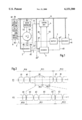
- FIG. 1 illustrates a schematic block diagram of an audio playback apparatus
- FIG. 2 illustrates a time diagram of an interleaved data format.
- the input data stream fed to the audio playback apparatus is formed according to the usual standardized data format, but the data field contains the audio information of the audio data source not directly, but indirectly as a second standardized data format which is contained in the data field of the first standardized data format.
- the input decoder has, in addition to a first data output, at which the audio information is provided as a first data stream as heretofore, a second data output at which the data contained in the data field of the standardized data format are provided as a second data stream.
- This second data stream is fed to an additional decoder which detects at least the second standardized data format and which passes the audio information contained therein to the output decoder as a third data stream.
- the additional decoder further provides a detection signal to a control unit which sets the output decoder to the processing of either of the data streams in response to this detection signal.
- the audio data source corresponds essentially to a storage device which contains audio signal data for an audio playback apparatus in a standardized data format in which the data fields of successive data packets contain no audio data, but a further standardized data format which contains the compressed audio data in its data field.
- the second related object is attained by providing a programming device for a storage device which places the audio information on the storage device in an interleaved data format, with the two interleaved data formats corresponding to respective standardized data formats.
- the programming device causes a reversal of the signal processing of the additional and input decoders according to the audio playback apparatus in accordance with the invention. These functional units are followed by the usual write device.
- the different compression factors of the second data format are included as information in an auxiliary-data field.
- the data compression involves a reduction of the data rate of the input data stream. If the audio data source is a storage device, the read clock rate must change in accordance with the compression factor. The use of oversampling during the reading of CDs is of no significance in this connection. In the case of mechanically driven storage devices, such as CDs, the data rate to be read out is adapted to the respective compression factor by controlling the speed of the motor.
- the output decoder is fed only genuine audio data, it is preferably muted during the switching of the data streams. To shorten these time intervals, temporal compensation is used between the two audio data streams.
- FIG. 1 shows the individual functional units of an audio playback apparatus according to the invention in block-diagram form.
- An audio data source 1 delivers an input data current do to an input decoder 2, a first data output of which provides a first data stream d1, which is error-corrected by means of correction data in the usual manner. Since a clock signal and an identification signal are transferred in addition to the data, the data bus for the first data stream d1 preferably has three leads.
- the input decoder 2 has a second data output which delivers a second data stream d2 that corresponds to the error-corrected data field D1 of the input data stream d0. Since in addition to these data, a clock signal is transferred to the additional decoder 3, the associated data bus preferably has two leads.
- the second data stream d2 can also be fed to the additional decoder 3 as an external data stream d2* via a separate terminal. Such a terminal is appropriate, for example, if the audio playback apparatus is connected to, or forms part of, a computer with which audio data sources are accessed via the Internet, for example.
- the input decoder 2 provides an error signal f1, which is fed to a control unit 4.
- the additional decoder 3 also provides an error signal f2 to the control unit 4, which can mute an output decoder 5 in response to these error signals f1, f2.
- the error signals f1, f2 are formed if the associated decoders 2, 3 detect no evaluable data or if the data are so corrupted that correction is no longer possible.
- the additional decoder 3 continuously checks the data of the second data stream d2 for the presence of a known data format F2. If it detects such a data format, it sends a detection signal d2 to the control unit 4, signaling that an interleaved data format F1, F2 is present which it can process in accordance with its function. If the additional decoder 3 can detect two or more data formats, the detection signal dz will also include the associated format information for the control unit 4. The latter initiates the necessary switching operations in the audio playback apparatus via a control bus 6. If the audio data source 1 is a mechanically driven playback device, such as a CD drive or a magnetic tape drive, the controller 4 will adapt the speed to the reduced sampling rate via a motor controller 1.5.
- the additional decoder 3 supplies the decoded audio data as a third data stream d3 to the output decoder 5. Since the additional decoder 3 follows the input decoder 2, the third data stream d3 is delayed with respect to the first data stream d1. To avoid any excessive interference intervals for the muting in the output decoder 5 during the switching from the first data stream d1 to the third data stream d3 and vice versa, the first data stream d1 is delayed in a buffer 7 by approximately an amount equal to the processing time of the second data stream d2 in the additional decoder 3, forming the data stream d1*.
- the switching of the first and third data streams d1*, d3 is accomplished either by means of an electronic switch or by tri-state control of the data outputs of the buffer 7 and the additional decoder 3.
- the data lines can be connected together and be coupled to a single data input of the output decoder 5.
- the control of the tri-state data outputs is effected by the control unit 4 via the control bus 6.
- the audio data source 1 is shown schematically as a CD player.
- a rotating compact disk 1.6 is optically scanned by the input decoder 2 and generates the input data stream d0.
- the optical scanning by the input decoder 2 is indicated by a dashed line op.
- the storage device 1.6 in the audio data source 1 should be easily exchangeable. That is the case with the change mechanisms of conventional CD drives and even more if the CD size is reduced. As the storage capacity of solid-state memories increases, however, mechanically driven storage devices are likely to be replaced, at least in some areas, by exchangeable mass storage devices, thus eliminating the need for the relatively complex and trouble-prone mechanical systems.
- FIG. 1 shows, in the form of blocks, a programming device 8 which generates the interleaved data format for the storage device 1.6.
- the programming device 8 contains, in the direction of signal flow, a first encoder 8.1, a second encoder 8.2, and a write device 8.3.
- the second encoder 8.2 and the write device 8.3 correspond to the functional blocks of commercially available write devices for the standardized data format F1, which are known for CDs by the term "burners".
- the audio data to be stored, dx are first converted by the first encoder 8.1 to the second standardized data format F2 to form a data stream ds which is fed as a "quasi-audio data stream" to the second encoder 8.2 for conversion to the first data format F1.
- the resulting data stream dw corresponds to the first standardized data format F1 and is written on the storage device 1.6 by means of the write device 8.3.
- the advantage of the invention lies in the fact that the playback apparatus is highly flexible as it can process at least one of the commonly used data formats, but also additional data formats which permit a high level of compression.
- the playing time of existing storage devices 1.6 can thus be significantly increased. This applies already for recordings of normal or high quality. A further prolongation of the playing time is achieved if a lower quality level is used for recording and reproduction, e.g., for voice recording and voice reproduction.
- Another advantage is that if individual circuits are to be implemented using monolithic integrated circuit technology, the additional complexity is low, because functions are at least partially executed in a multiplex mode or performed by processors which are not used to capacity.
- FIG. 2 illustrates a scheme of the interleaved data formats.
- the first standardized data format F1 which is transmitted in successive data packets P1.0, P1.1, P1.2, contains a sync field S1 for synchronizing the data packets at the receiving end, then an auxiliary-data field A1, which may contain information on the respective data standard, the length of the data format, or other information, then the data field D1, containing the audio data along with an error-correcting code, and finally an end field E1, which signals the end of the respective data format and data packet.
- This basic data structure permits deviations in the type and length of the individual blocks etc. Additional fields may be provided, or other fields, which may also recur.
- the subsequent data packet P1.2 contains the same blocks, i.e., the sync field S1, the auxiliary-data field A1, etc.
- the second standard data format F2 which also defines the data structure in the successive data packets, does not basically differ from the structure of the first data format F1.
- Sync information S2 is followed by auxiliary data A2, which in the case of the MPEG standard, for example, defines the respective compression factor of the audio information contained in data field D2.
- the length of the data packets is specified either in the auxiliary-data field A2 or by the end information E2.
- the data packet P2.1 is followed by the new data packet P2.2, which has the same structure.
- the time axis t in the representation of the data format F2 is extended in comparison with that of the representation of the data format F1.
Abstract
Description
Claims (20)
Applications Claiming Priority (2)
| Application Number | Priority Date | Filing Date | Title |
|---|---|---|---|
| EP98102921 | 1998-02-19 | ||
| EP98102921A EP0938090B1 (en) | 1998-02-19 | 1998-02-19 | Audio reproducing device |
Publications (1)
| Publication Number | Publication Date |
|---|---|
| US6151580A true US6151580A (en) | 2000-11-21 |
Family
ID=8231449
Family Applications (1)
| Application Number | Title | Priority Date | Filing Date |
|---|---|---|---|
| US09/251,502 Expired - Lifetime US6151580A (en) | 1998-02-19 | 1999-02-17 | Audio playback apparatus |
Country Status (5)
| Country | Link |
|---|---|
| US (1) | US6151580A (en) |
| EP (1) | EP0938090B1 (en) |
| JP (1) | JPH11317022A (en) |
| KR (1) | KR100527645B1 (en) |
| DE (1) | DE59808816D1 (en) |
Cited By (9)
| Publication number | Priority date | Publication date | Assignee | Title |
|---|---|---|---|---|
| US20010054167A1 (en) * | 2000-01-13 | 2001-12-20 | Olympus Optical Co., Ltd. | Data transfer system and data transfer method |
| US20040155449A1 (en) * | 2003-02-12 | 2004-08-12 | Nissan Motor Co., Ltd. | Mount structure for fuel tank |
| US6788634B1 (en) | 1999-07-15 | 2004-09-07 | Micronas Gmbh | Playback apparatus |
| US20040213350A1 (en) * | 2003-04-24 | 2004-10-28 | Frith Peter J. | Interface format for PCM and DSD devices |
| US20040215466A1 (en) * | 2001-08-06 | 2004-10-28 | Taylor Temeca Katherine | Digital audio manipulator |
| US20050183102A1 (en) * | 2004-02-05 | 2005-08-18 | Pioneer Corporation | Disk inserting/ejecting apparatus |
| US7092340B2 (en) | 2000-07-13 | 2006-08-15 | Micronas Gmbh | Playback apparatus |
| US20090313043A1 (en) * | 2006-09-08 | 2009-12-17 | American Well, Inc. A Delaware Corporation | Connecting Consumers with Service Providers |
| EP2312849A1 (en) | 2009-10-01 | 2011-04-20 | Nxp B.V. | Methods, systems and devices for compression of data and transmission thereof using video transmisssion standards |
Families Citing this family (1)
| Publication number | Priority date | Publication date | Assignee | Title |
|---|---|---|---|---|
| JP2001266488A (en) | 2000-03-23 | 2001-09-28 | Toshiba Corp | Unit and method for reproducing compressed audio data |
Citations (8)
| Publication number | Priority date | Publication date | Assignee | Title |
|---|---|---|---|---|
| US4348699A (en) * | 1979-05-15 | 1982-09-07 | Sony Corporation | Apparatus for recording and/or reproducing digital signal |
| EP0165320A1 (en) * | 1983-11-30 | 1985-12-27 | Sony Corporation | Disk-shaped recording medium and apparatus for reproducing the same |
| EP0543667A1 (en) * | 1991-11-22 | 1993-05-26 | Sony Corporation | Optical recording method of audio data |
| US5428593A (en) * | 1992-11-18 | 1995-06-27 | Sony Corporation | Digital audio signal transforming method and apparatus |
| WO1996030906A1 (en) * | 1995-03-30 | 1996-10-03 | Victor Company Of Japan, Ltd. | Information recording disk |
| DE19722466A1 (en) * | 1996-05-29 | 1997-12-04 | Sony Corp | Recording and reproduction component system especially for CD and MD |
| US5894480A (en) * | 1996-02-29 | 1999-04-13 | Apple Computer, Inc. | Method and apparatus for operating a multicast system on an unreliable network |
| US5902115A (en) * | 1995-04-14 | 1999-05-11 | Kabushiki Kaisha Toshiba | Recording medium on which attribute information on the playback data is recorded together with the playback data and a system for appropriately reproducing the playback data using the attribute information |
-
1998
- 1998-02-19 DE DE59808816T patent/DE59808816D1/en not_active Expired - Lifetime
- 1998-02-19 EP EP98102921A patent/EP0938090B1/en not_active Expired - Lifetime
-
1999
- 1999-02-12 KR KR10-1999-0004963A patent/KR100527645B1/en not_active IP Right Cessation
- 1999-02-17 US US09/251,502 patent/US6151580A/en not_active Expired - Lifetime
- 1999-02-17 JP JP11038177A patent/JPH11317022A/en active Pending
Patent Citations (8)
| Publication number | Priority date | Publication date | Assignee | Title |
|---|---|---|---|---|
| US4348699A (en) * | 1979-05-15 | 1982-09-07 | Sony Corporation | Apparatus for recording and/or reproducing digital signal |
| EP0165320A1 (en) * | 1983-11-30 | 1985-12-27 | Sony Corporation | Disk-shaped recording medium and apparatus for reproducing the same |
| EP0543667A1 (en) * | 1991-11-22 | 1993-05-26 | Sony Corporation | Optical recording method of audio data |
| US5428593A (en) * | 1992-11-18 | 1995-06-27 | Sony Corporation | Digital audio signal transforming method and apparatus |
| WO1996030906A1 (en) * | 1995-03-30 | 1996-10-03 | Victor Company Of Japan, Ltd. | Information recording disk |
| US5902115A (en) * | 1995-04-14 | 1999-05-11 | Kabushiki Kaisha Toshiba | Recording medium on which attribute information on the playback data is recorded together with the playback data and a system for appropriately reproducing the playback data using the attribute information |
| US5894480A (en) * | 1996-02-29 | 1999-04-13 | Apple Computer, Inc. | Method and apparatus for operating a multicast system on an unreliable network |
| DE19722466A1 (en) * | 1996-05-29 | 1997-12-04 | Sony Corp | Recording and reproduction component system especially for CD and MD |
Non-Patent Citations (1)
| Title |
|---|
| Copy of EP Search Report for EP 98 10 2921, dated Jul. 21, 1998. * |
Cited By (12)
| Publication number | Priority date | Publication date | Assignee | Title |
|---|---|---|---|---|
| US6788634B1 (en) | 1999-07-15 | 2004-09-07 | Micronas Gmbh | Playback apparatus |
| US20010054167A1 (en) * | 2000-01-13 | 2001-12-20 | Olympus Optical Co., Ltd. | Data transfer system and data transfer method |
| US6741964B2 (en) * | 2000-01-13 | 2004-05-25 | Olympus Optical Co., Ltd. | Data transfer system and data transfer method |
| US7092340B2 (en) | 2000-07-13 | 2006-08-15 | Micronas Gmbh | Playback apparatus |
| US20040215466A1 (en) * | 2001-08-06 | 2004-10-28 | Taylor Temeca Katherine | Digital audio manipulator |
| US20040155449A1 (en) * | 2003-02-12 | 2004-08-12 | Nissan Motor Co., Ltd. | Mount structure for fuel tank |
| US20040213350A1 (en) * | 2003-04-24 | 2004-10-28 | Frith Peter J. | Interface format for PCM and DSD devices |
| US20050183102A1 (en) * | 2004-02-05 | 2005-08-18 | Pioneer Corporation | Disk inserting/ejecting apparatus |
| US20090313043A1 (en) * | 2006-09-08 | 2009-12-17 | American Well, Inc. A Delaware Corporation | Connecting Consumers with Service Providers |
| US7835928B2 (en) * | 2006-09-08 | 2010-11-16 | American Well Corporation | Connecting consumers with service providers |
| EP2312849A1 (en) | 2009-10-01 | 2011-04-20 | Nxp B.V. | Methods, systems and devices for compression of data and transmission thereof using video transmisssion standards |
| US20110103472A1 (en) * | 2009-10-01 | 2011-05-05 | Nxp B.V. | Methods, systems and devices for compression of data and transmission thereof using video transmission standards |
Also Published As
| Publication number | Publication date |
|---|---|
| DE59808816D1 (en) | 2003-07-31 |
| KR19990072628A (en) | 1999-09-27 |
| JPH11317022A (en) | 1999-11-16 |
| KR100527645B1 (en) | 2005-11-15 |
| EP0938090A1 (en) | 1999-08-25 |
| EP0938090B1 (en) | 2003-06-25 |
Similar Documents
| Publication | Publication Date | Title |
|---|---|---|
| EP0920698B1 (en) | Apparatus and method for reproducing a digital audio signal from a record carrier | |
| US6151580A (en) | Audio playback apparatus | |
| JPH024070B2 (en) | ||
| EP0390576A1 (en) | Recording/reproducing apparatus | |
| WO1995028061A3 (en) | Recording and reproduction of a trick mode video signal | |
| US7092340B2 (en) | Playback apparatus | |
| US6788634B1 (en) | Playback apparatus | |
| KR20020000727A (en) | Audio and video recording and reproduction apparatus | |
| US20050246180A1 (en) | Audio signal process circuit | |
| US20050201737A1 (en) | Optical recording and/or reproducing apparatus having codec/IEEE1394 link one-chip | |
| JP2884591B2 (en) | Audio signal input / output switching device in electronic equipment | |
| US7574116B2 (en) | Optical disc apparatus | |
| CN1130718C (en) | Audio-frequence playback equipment | |
| KR100233653B1 (en) | The still picture reproducing system of video cd for error data | |
| KR0135483B1 (en) | Cd-rom drive circuit | |
| KR850001676B1 (en) | Signal copy device for digital record reproduction system | |
| KR0162330B1 (en) | Device for trick-paly of optical disc | |
| KR100191314B1 (en) | Reproducer of multi-channel audio signal | |
| KR100357123B1 (en) | Method for speed change playback of dvcr | |
| KR200147770Y1 (en) | Audio signal processor | |
| EP1158512A1 (en) | Audio output control device | |
| JP2002262226A (en) | Recording, reproducing and editing device and method | |
| JPS58146012A (en) | Digital data transmitting device | |
| JPH0415547B2 (en) | ||
| JPH1166697A (en) | Dubbing control method |
Legal Events
| Date | Code | Title | Description |
|---|---|---|---|
| AS | Assignment |
Owner name: MICRONAS INTERMETALL GMBH, GERMANY Free format text: ASSIGNMENT OF ASSIGNORS INTEREST;ASSIGNORS:BACHER, DIETER;BECHER, JUERGEN;MEINER, JUERGEN;REEL/FRAME:009788/0227 Effective date: 19990205 |
|
| STCF | Information on status: patent grant |
Free format text: PATENTED CASE |
|
| FEPP | Fee payment procedure |
Free format text: PAYOR NUMBER ASSIGNED (ORIGINAL EVENT CODE: ASPN); ENTITY STATUS OF PATENT OWNER: LARGE ENTITY |
|
| FPAY | Fee payment |
Year of fee payment: 4 |
|
| FEPP | Fee payment procedure |
Free format text: PAYER NUMBER DE-ASSIGNED (ORIGINAL EVENT CODE: RMPN); ENTITY STATUS OF PATENT OWNER: LARGE ENTITY Free format text: PAYOR NUMBER ASSIGNED (ORIGINAL EVENT CODE: ASPN); ENTITY STATUS OF PATENT OWNER: LARGE ENTITY |
|
| FPAY | Fee payment |
Year of fee payment: 8 |
|
| AS | Assignment |
Owner name: ENTROPIC COMMUNICATIONS, INC., CALIFORNIA Free format text: ASSIGNMENT OF ASSIGNORS INTEREST;ASSIGNORS:TRIDENT MICROSYSTEMS, INC.;TRIDENT MICROSYSTEMS (FAR EAST) LTD.;REEL/FRAME:028153/0530 Effective date: 20120411 |
|
| FPAY | Fee payment |
Year of fee payment: 12 |
|
| AS | Assignment |
Owner name: ENTROPIC COMMUNICATIONS, INC., CALIFORNIA Free format text: MERGER AND CHANGE OF NAME;ASSIGNORS:EXCALIBUR ACQUISITION CORPORATION;ENTROPIC COMMUNICATIONS, INC.;ENTROPIC COMMUNICATIONS, INC.;REEL/FRAME:035706/0267 Effective date: 20150430 |
|
| AS | Assignment |
Owner name: ENTROPIC COMMUNICATIONS, LLC, CALIFORNIA Free format text: MERGER AND CHANGE OF NAME;ASSIGNORS:ENTROPIC COMMUNICATIONS, INC.;EXCALIBUR SUBSIDIARY, LLC;ENTROPIC COMMUNICATIONS, LLC;REEL/FRAME:035717/0628 Effective date: 20150430 |