US6151398A - Magnetic film ultrasonic emitter - Google Patents
Magnetic film ultrasonic emitter Download PDFInfo
- Publication number
- US6151398A US6151398A US09/006,134 US613498A US6151398A US 6151398 A US6151398 A US 6151398A US 613498 A US613498 A US 613498A US 6151398 A US6151398 A US 6151398A
- Authority
- US
- United States
- Prior art keywords
- diaphragm
- coil
- magnetic field
- coils
- conductive
- Prior art date
- Legal status (The legal status is an assumption and is not a legal conclusion. Google has not performed a legal analysis and makes no representation as to the accuracy of the status listed.)
- Expired - Lifetime
Links
Images
Classifications
-
- G—PHYSICS
- G10—MUSICAL INSTRUMENTS; ACOUSTICS
- G10K—SOUND-PRODUCING DEVICES; METHODS OR DEVICES FOR PROTECTING AGAINST, OR FOR DAMPING, NOISE OR OTHER ACOUSTIC WAVES IN GENERAL; ACOUSTICS NOT OTHERWISE PROVIDED FOR
- G10K9/00—Devices in which sound is produced by vibrating a diaphragm or analogous element, e.g. fog horns, vehicle hooters or buzzers
- G10K9/12—Devices in which sound is produced by vibrating a diaphragm or analogous element, e.g. fog horns, vehicle hooters or buzzers electrically operated
- G10K9/13—Devices in which sound is produced by vibrating a diaphragm or analogous element, e.g. fog horns, vehicle hooters or buzzers electrically operated using electromagnetic driving means
Definitions
- This invention pertains to propagation of ultrasonic frequencies from a thin diaphragm emitter. Specifically, the present invention relates to a device and method for indirectly generating a new sonic or subsonic compression wave by interaction of two ultrasonic signals having frequencies whose difference in value corresponds to the desired new sonic or subsonic compression wave frequencies.
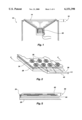
- FIG. 1 illustrates a graphic representation of a conventional audio speaker 10 using a moveable diaphragm 14.
- Diaphragm movement 18 is regulated by energy from a magnetic core which drives a stator 22 in a reciprocating manner within an annular recess of the coil.
- the conversion of electrical signal to sonic compression wave is developed by the variable current or voltage applied to the stator, resulting in a variable magnetic field which is attracted or repulsed with respect to the magnetic core.
- the diaphragm attached to the stator is displaced to mechanically reproduce the variable frequency and amplitude of the electrical signal in the form of a compression wave.
- Amplitude of the compression wave is primarily a function of the diameter of the diaphragm, and extent of orthogonal displacement. Physically, this corresponds to the volume of air being moved with each stroke of the speaker membrane.
- Attempts to reproduce sound without use of a moving diaphragm include technologies embodied in parametric speakers, acoustic heterodyning, beat frequency interference and other forms of modulation of multiple frequencies to generate a new frequency.
- sound is developed by the interaction in air (as a nonlinear medium) of two ultrasonic frequencies whose difference in value falls within the audio range.
- resulting compression waves would be projected within the air as a nonlinear medium, and would be heard as pure sound.
- general production of sound by acoustic heterodyning for practical applications has alluded the industry for over 100 years.
- Ultrasonic frequencies have comparatively small wave lengths and are generally characterized by nominal diaphragm displacement. This limited movement of the diaphragm or emitter membrane contributes to inadequate volume for the parametric output, as well as lack of extended range for projection of the resulting sonic waves generated by interference of the two ultrasonic frequencies well. It is not surprising that amplitude would be a problem in such a system where frequencies well in excess of 40,000 Hz tend to limit the excursion length for diaphragm displacement.
- the proposed device comprises a transducer which radiates the dual ultrasonic frequencies to generate the desired audio difference signal.
- the dual-frequency, ultrasonic signal is propagated from a gel medium on the face of the transducer.
- This medium 20 "serves as a virtual acoustic source that produces the difference tone 23 whose frequency corresponds to the difference between frequencies f1 and f2.” Col 4, lines 54-60.
- this 1994 reference abandons direct generation of the difference audio signal in air from the face of the transducer, and depends upon the nonlinearity of a gel medium to produce sound. This abrupt shift from transducer/air interface to proposed use of a gel medium reinforces the perception of apparent inoperativeness of prior art disclosures, at least for practical speaker applications.
- Electrostatic emitters for ultrasonic wave generation have been applied in many areas of technology, but have equally limited diaphragm displacement.
- ultrasonic emitters in range finder devices for cameras and distance measuring devices produce high frequencies, but with very little amplitude.
- U.S. Pat. No. 5,287,331 by Schindel illustrates devices which can generate extremely high frequencies up to 2 MHZ, but have an orthogonal displacement in micrometers. Because of the weakness of electrostatic forces, it is generally expected that diaphragm displacement will be nominal, as will be the resulting amplitude of ultrasonic or sonic output.
- a still further object of this invention is to provide an improved speaker diaphragm capable of generating high amplitude compression waves in response to electrical stimulation, yet which does not require a rigid diaphragm structure of a conventional audio speaker or ultrasonic transducer.
- the above objects and others not specifically recited are realized through a method and apparatus for an ultrasonic emitter device having broad frequency range capacity with relatively large diaphragm displacement compared to typical electrostatic diaphragm movement.
- the device includes a core member able to establish a first magnetic field.
- a movable diaphragm is stretched along the core member and displaced a short separation distance from the core member to allow an intended range of orthogonal displacement of the diaphragm with respect to the core member and within a strong portion of the magnetic field.
- At least one, low mass, planar, conductive coil is disposed on the movable diaphragm and includes first and second contacts for enabling current flow through the coil.
- a variable current flow is applied to the coil for developing a second magnetic field which variably interacts with the first magnetic field to attract and repel the diaphragm at a desired frequency for development of a series of compression waves which may include an ultrasonic frequency range.
- FIG. 1 is cross-sectional, side view in graphical representation of a conventional audio speaker having a magnetic core and moveable diaphragm.
- FIG. 2 is a top perspective view showing a thin film diaphragm having a plurality of magnetic coils disposed on the emitter diaphragm and suspended over a magnetic core element in accordance with the principles of the present invention.
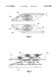
- FIG. 3 is an exploded view of an alternate embodiment showing opposing magnetic coils on the emitter diaphragm and core.
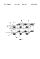
- FIG. 4 is a graphic, elevational perspective view of a preferred embodiment of the present invention showing an emitter membrane disposed above a compartmentalized magnetic core.
- FIG. 5 is a cut-away profile view of the emitter diaphragm of FIG. 2, taken along the lines 5--5.
- FIG. 6 is a cut-away profile view of an alternative embodiment wherein the emitter diaphragm includes additional magnetic coils disposed on an opposing side of the diaphragm.
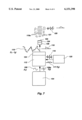
- FIG. 7 is a more specific implementation of the present invention which transmits an ultrasonic base frequency and an ultrasonic intelligence carrying frequency which acoustically heterodyne to generate a new sonic or subsonic frequency.
- FIG. 2 depicts one of the preferred configurations of the present invention. Specifically, it comprises an ultrasonic emitter having broad frequency range capacity with relatively large diaphragm displacement compared to the nominal movement of a typical electrostatic diaphragm. Indeed, orthogonal displacement (peak to peak movement of the diaphragm from a full extended to a full retracted position) may be as great as 0.5 mm. This compares very favorably with a movement range of 0.1 to 3 micrometers for a rigid transducer emitter face.
- the benefits of extended motion for the magnetic diaphragm of the present invention include a significant increase in amplitude in ultrasonic, as well as sonic output for a parametric array.
- the enhanced sonic output of the present invention is enabled by use of a magnetic field generated by a magnetic core member 26.
- This core may be a permanent magnet or a composition adapted for electromagnetic use.
- Such materials may be either flexible or rigid, depending upon the configuration of the speaker array. For example, a planar plate will generate a column of sound which has surprising projection capacity over long distances.
- a curved emitter diaphragm may be formed and supported by a curved support core made of flexible magnet material similar to removable magnets attached to appliances, etc.
- This curved configuration provides a greater dispersion pattern for projected sound, and also enables a sense of directional movement to emitted sound. This can be implemented by sequentially triggering sound transmission along a linear sequence of emitter elements (or conductive coils) 30 disposed along the diaphragm 34. When these elements are radiated outward in a diverging configuration, the audience perceives the source as having a physical element of motion along that direction.
- a permanent, rigid magnetic core or plate 26 has been used as a support for the flexible emitter diaphragm 34.
- This permanent magnet 26 operates as the primary means for establishing a first magnetic field adjacent the core member, in a manner similar to the permanent magnet of an acoustic speaker. In this case, however, there is no telescopic core or recess which receives the stator element. Instead, the core 26 is a planar body which establishes a uniform magnetic field along its length, thereby providing necessary counter force for a variable magnetic field to be established in the diaphragm 34.
- the illustrated movable diaphragm 34 is stretched along the core member 26 and displaced a short separation distance from the core member to allow an intended range of orthogonal displacement of the diaphragm with respect to the core member and within a strong portion of the magnetic field.
- this diaphragm 34 comprises a thin film of mylar or other strong, lightweight polymer. Many such materials are already in use in the electrostatic speaker or ultrasonic emitter industry.
- the enhanced displacement of the diaphragm 34 is enabled by at least one, low mass, planar, conductive coil (or emitter element 30) disposed on the movable diaphragm.
- the thin conductive coil 30 creates a magnetic field when current is conducted through the coil.
- the present inventor has discovered that the power of a magnetic field can be implemented in a voice coil disposed on planar film, yielding the benefits of substantial diaphragm 34 displacement far beyond prior art electrostatic speaker systems.
- This current is supplied to the coil 30 by first and second contacts 38 and 42 which are coupled to a power source.
- the first contact 38 is coupled to one end of the coil 30, typically at a side common with the coil itself.
- the second contact 42 is disposed on the opposing side of the coil 30, thereby providing electrical isolation from the first contact 38.
- the illustrated embodiment shows the second contact 42 penetrating the film (or diaphragm 34) and extending along the opposite face of the film to a pick up point for closing the circuit for current flow.
- Other methods of electrically isolating the respective first and second contacts will be apparent to those skilled in the art.
- the planar voice coil 30 may be placed on the diaphragm 34 by many procedures well known in the art. For example, multiple coil elements can be simultaneously vapor deposited on a Mylar® film with a template or mask. Similarly, the coils may be printed individually, or concurrently, with multiple print heads or plates. The reverse process can also be implemented with various etching techniques wherein the coil elements remain after metallic coating is etched from the film by laser or chemical reaction. Other forms of application or deposition may be applied in accordance with conventional methods.
- Both vapor deposition and etching techniques provide very thin or fine coil elements 30 which provide the desired magnetic field.
- the preferred embodiment of the present invention adopts a single plane for the coil, relying on spiral configuration rather than a helix to develop the coil configuration.
- Typical spiral patterns comprise thin line dimensions of approximately 100 micrometers, separated by open spaces or gaps of approximately 10 micrometers. This enables a coil of approximately 20 to 50 rings or spiral elements in a one inch diameter coil.
- Utilization of the present invention of magnetic voice coils 30 enables the addition of very little weight to the diaphragm 34, providing a low mass speaker system capable of oscillating at high ultrasonic frequencies, yet still having substantial orthogonal displacement.
- the weight of the diaphragm 34 is slightly higher than the mass of the Mylar film itself, and is therefore closely comparable therefore to an electrostatic membrane. Nevertheless, the power output of the magnetic coils greatly exceeds that of an electrostatic speaker, giving far greater amplitude to speaker output.
- a second magnetic field is generated which variably interacts with the first magnetic field established in the core 26.
- the permanent field of the core 26 allows this first field to attract and repel the diaphragm 34 at a desired frequency for development of a series of compression waves which may be operated within an ultrasonic frequency range.
- this variable current source includes a carrier frequency which has been modulated with a voice or musical signal
- a resulting dual ultrasonic frequency output is generated capable of emitting a new sonic emission in accordance with principles of acoustic heterodyning.
- This second magnetic field may have a field strength as much as 10 times the field strength of an electrostatic field.
- the core member 26 may comprise a permanent magnet.
- This permanent magnet may be a rigid plate of magnetic material having dimensions slightly larger than dimensions of an active emitting surface of the emitter device. Examples of such materials are well known to those of ordinary skill in the art, and would include a rigid, flat plate of iron or other paramagnetic material with uniform magnetic field along its surface.
- the permanent magnet may be a flexible magnetic plate or sheet similar to magnetic "stick-on" devices applied to refrigerators and other metallic appliances or surfaces.
- a further alternate embodiment of the core member 26 could comprise a rigid plate 46 formed of nonmagnetic composition, one surface of which includes at least one opposing conductive coil 50 similar in design to the conductive coil 30 described for the vibrating diaphragm above.
- a coil would include first and second contacts 54 and 58 for enabling current flow through the opposing conductive coil 50 to thereby establish the required second magnetic field.
- This at least one opposing conductive coil 50 would be positioned on the rigid plate in a location which is juxtaposed to the at least one conductive coil 30 on the vibrating or movable diaphragm 34 to enable the at least one conductive coil 30 and the at least one opposing conductive coil 50 to cause respective magnetic fields from each coil to interact to develop the compression waves emitted from the diaphragm.
- the first contact 54 is positioned on one side of the diaphragm and the second contact 58 is positioned on an opposing side of the diaphragm.
- This may be in the form of a single coil as illustrated in FIG. 3, or as a plurality of conductive coils equally spaced along the diaphragm as depicted in FIG. 2.
- the conductive coils 30 and 50 are disposed in a plurality of rows in juxtaposed position to maximize uniformity of the magnetic field, as well as the quantity of coil applied.
- each coil it is possible to partially isolate each coil by providing a support perimeter in contact with the diaphragm around each of the conductive coils.
- a grid configuration 62 defines a plurality of open displacement cavities 66 at a surface of the core member 70 adjacent to the diaphragm 74, each cavity being aligned with one of the conductive coils 78.
- These displacement cavities 66 are of equal dimension to conform to the equally spaced voice coils 78 which they respectively support.
- the advantages of physically isolating the respective voice coils 78 include reduction in anomalies within the vibrating diaphragm 74 which could arise from variations in physical properties of the film or diaphragm, as well as electrical properties which might propagate between coils from hysteresis or other forms of magnetic coupling that might be amplified by uninhibited transmission of vibrations between coil sectors.
- the supporting grid members operate to dampen such vibration where the diaphragm 74 is biased in contact with the grid face or edge surface. In this sense, each grid and coil sector becomes an autonomous speaker element which is controlled by the applied voltage through the coil. Where the voltage source is common and the coil elements are congruent, the output should be equal. Consequently, all coil sectors having common output will generate a uniform wave front substantially free of distortion arising from physical or electrical perturbations.
- Physical distortion can be further minimized by ensuring that the film material is uniform or isotropic in its response characteristics. In this manner, elongation or stretching of the material in response to attraction or repulsion remains uniform across the array of coils. This response can also be affected by maintaining sufficient thickness in the film to reduce elongation to near zero. Vibration response is then limited to the actual displacement 82 of the film 34 between extreme positions of convex extension 83 to concave retraction 84 as illustrated in FIG. 5. In contrast with an electrostatic system wherein the force of electrostatic charges may be insufficient to fully displace the supporting film, the voice coils 30 supply additional mass and magnetic force to give greater extension and retraction.
- a voltage or control source is required as a means for supplying variable current flow to control current flow to the at least one conductive coil 30 and/or the at least one opposing conductive coil 50 where utilized. This is necessary to ensure that each coil generates a variable magnetic field which is capable of enhancing the desired repulsion and attraction arising between the respective coils.
- the control source need only supply a voltage to voice coils 30 disposed on the vibrating film or diaphragm 34. Obviously, if the core 26 does not provide a permanent form of magnetic field, a voltage supply source would have to be applied to develop an electromagnetic force at the core which is operable with respect to the at least one conductive coil 30 to develop the desired diaphragm 34 displacement.
- FIG. 6 illustrates the use of a plurality of conductive coils 86 on the diaphragm 90 and a corresponding plurality of conductive coils 94 juxtaposed on an opposing side of the diaphragm 90 to further enhance the secondary magnetic force field generated at the diaphragm.
- the film or diaphragm 90
- Both sets of coils (86 and 87) would be powered by the same voltage source to generate common magnetic fields. These fields would be of equal polarity and would commonly reinforce each other.
- the present invention enables a method for emitting a broad frequency range including ultrasonic frequencies utilizing a magnetically activated diaphragm or film comparable to an electrostatic diaphragm.
- the method offers increased audio amplitude because of a greatly enhanced capacity for relatively large diaphragm displacement as compared to lesser movement of a typical electrostatic diaphragm.
- This method comprises the basic steps of (i) providing a first magnetic field adjacent a supporting core member 26; (ii) applying at least one conductive coil 30 to a movable diaphragm 34 stretched along the core member and displaced a short separation distance from the core member to allow an intended range of orthogonal displacement of the diaphragm with respect to the core member and within a strong portion of the first magnetic field; (iii) and supplying variable current flow to the at least one coil 30 for developing a second magnetic field which variably interacts with the first magnetic field to attract and repel the diaphragm at a desired frequency for development of a series of compression waves which may be adjusted to include an ultrasonic frequency range.
- the embodiment of FIG. 4 requires consideration of resonant frequency as a function of various characteristics of the vibrating diaphragm and core structure. These characteristics include, among other things, the thickness of the film 74 stretched across the support core 70, as well as the diameter of the grid cavities 62 in the core structure. Using a thinner film 74 will obviously result in more rapid vibrations of the film 74 for a given applied voltage. Consequently, the resonant frequency of the film 74 (or diaphragm) will be higher.
- a magnetic diaphragm 100 can be included in the system shown in FIG. 7 supported on a driver unit 138.
- This application utilizes a parametric or heterodyning technology, which is particularly adapted for the present thin film structure.
- the thin magnetic film of the present invention is well suited for operation at high ultrasonic frequencies in accordance with parametric speaker theory.
- a basic system includes an oscillator or digital ultrasonic wave source 104 for providing a base or carrier wave 108.
- This wave 108 is generally referred to as a first ultrasonic wave or primary wave.
- An amplitude modulating component 112 is coupled to the output of the ultrasonic generator 104 and receives the base frequency 108 for mixing with a sonic or subsonic input signal 116.
- the sonic or subsonic signal 116 may be supplied in either analog or digital form, and could be music from any convention signal source 120 or other form of sound. If the input signal 116 includes upper and lower sidebands 117, a filter component 124 may be included in the modulator to yield a single sideband output 118 on the modulated carrier frequency for selected bandwidths (collectively identified as signal 119).
- the magnetic diaphragm 100 is caused to emit the ultrasonic frequencies f 1 and f 2 as a new wave form 119a propagated at the face of the magnetic diaphragm 100.
- This new wave form interacts within the nonlinear medium of air 121 to generate the difference frequency 120, as a new sonic or subsonic wave.
- the ability to have large quantities of emitter elements formed in an emitter disk is particularly well suited for generation of a uniform wave front which can propagate quality audio output at meaningful volumes.
- the present invention is able to function as described because the compression waves corresponding to f 1 and f 2 interfere in air according to the principles of acoustical heterodyning.
- Acoustical heterodyning is somewhat of a mechanical counterpart to the electrical heterodyning effect which takes place in a non-linear circuit.
- amplitude modulation in an electrical circuit is a heterodyning process.
- the heterodyne process itself is simply the creation of two new waves. The new waves are the sum and the difference of two fundamental waves.
- the new waves equaling the sum and difference of the fundamental waves are observed to occur when at least two ultrasonic signals interact or interfere in air.
- the preferred transmission medium of the present invention is air because it is a highly compressible medium that responds non-linearly under different conditions. This non-linearity of air enables the heterodyning process to take place, decoupling the difference signal from the ultrasonic output.
- any compressible fluid can function as the transmission medium if desired.
- An important feature of the present invention is that the base frequency and single or double sidebands are propagated from the same transducer face. Therefore the component waves are perfectly collimated. Furthermore, phase alignment is at maximum, providing the highest level of interference possible between two different ultrasonic frequencies. With maximum interference insured between these waves, one achieves the greatest energy transfer to the air molecules, which effectively become the "speaker" radiating element in a parametric speaker. Accordingly, the inventor believes the enhancement of these factors within a thin film, ultrasonic emitter array as provided in the present invention has developed a surprising increase in volume to the audio output signal.
- this aspect of the present invention means that technology is now approaching the final step of achieving truly pure sound reproduction. Distortion free sound implies that the present invention maintains phase coherency relative to the originally recorded sound.
- Conventional speaker systems do not have this capacity because the frequency spectrum is broken apart by a cross-over network for propagation by the most suitable speaker element (woofer, midrange or tweeter). By eliminating the radiating element, the present invention obsoletes the conventional cross-over network frequency and phase controls.
- the preferred and alternative embodiments can emit sonic frequencies directly, without having to resort to the acoustical heterodyning process described earlier.
- the range of frequencies in the audible spectrum is necessarily limited to generally higher frequencies, as the invention is unable to generate low or subsonic frequencies. Therefore, the greatest advantages of the present invention are realized when the invention is used to generate the entire range of audible frequencies indirectly using acoustical heterodyning as explained above.
Abstract
Description
Claims (28)
Priority Applications (2)
| Application Number | Priority Date | Filing Date | Title |
|---|---|---|---|
| US09/006,134 US6151398A (en) | 1998-01-13 | 1998-01-13 | Magnetic film ultrasonic emitter |
| US11/121,151 US20050244016A1 (en) | 1997-03-17 | 2005-05-02 | Parametric loudspeaker with electro-acoustical diaphragm transducer |
Applications Claiming Priority (1)
| Application Number | Priority Date | Filing Date | Title |
|---|---|---|---|
| US09/006,134 US6151398A (en) | 1998-01-13 | 1998-01-13 | Magnetic film ultrasonic emitter |
Related Parent Applications (1)
| Application Number | Title | Priority Date | Filing Date |
|---|---|---|---|
| US09/006,689 Continuation-In-Part US6108433A (en) | 1997-03-17 | 1998-01-13 | Method and apparatus for a magnetically induced speaker diaphragm |
Related Child Applications (1)
| Application Number | Title | Priority Date | Filing Date |
|---|---|---|---|
| US09/105,380 Continuation-In-Part US6188772B1 (en) | 1997-03-17 | 1998-06-26 | Electrostatic speaker with foam stator |
Publications (1)
| Publication Number | Publication Date |
|---|---|
| US6151398A true US6151398A (en) | 2000-11-21 |
Family
ID=21719475
Family Applications (1)
| Application Number | Title | Priority Date | Filing Date |
|---|---|---|---|
| US09/006,134 Expired - Lifetime US6151398A (en) | 1997-03-17 | 1998-01-13 | Magnetic film ultrasonic emitter |
Country Status (1)
| Country | Link |
|---|---|
| US (1) | US6151398A (en) |
Cited By (22)
| Publication number | Priority date | Publication date | Assignee | Title |
|---|---|---|---|---|
| US6606389B1 (en) * | 1997-03-17 | 2003-08-12 | American Technology Corporation | Piezoelectric film sonic emitter |
| WO2004019653A2 (en) * | 2002-08-26 | 2004-03-04 | Frank Joseph Pompei | Parametric array modulation and processing method |
| US6771785B2 (en) | 2001-10-09 | 2004-08-03 | Frank Joseph Pompei | Ultrasonic transducer for parametric array |
| US20040208324A1 (en) * | 2003-04-15 | 2004-10-21 | Cheung Kwok Wai | Method and apparatus for localized delivery of audio sound for enhanced privacy |
| US20050100181A1 (en) * | 1998-09-24 | 2005-05-12 | Particle Measuring Systems, Inc. | Parametric transducer having an emitter film |
| US20050244016A1 (en) * | 1997-03-17 | 2005-11-03 | American Technology Corporation | Parametric loudspeaker with electro-acoustical diaphragm transducer |
| EP1652728A1 (en) | 2004-11-02 | 2006-05-03 | Preco Electronics, Inc. | Safety alarm system |
| US7463165B1 (en) | 2005-08-31 | 2008-12-09 | Preco Electronics, Inc. | Directional back-up alarm |
| US20110103614A1 (en) * | 2003-04-15 | 2011-05-05 | Ipventure, Inc. | Hybrid audio delivery system and method therefor |
| US8199931B1 (en) | 1999-10-29 | 2012-06-12 | American Technology Corporation | Parametric loudspeaker with improved phase characteristics |
| US8275137B1 (en) | 2007-03-22 | 2012-09-25 | Parametric Sound Corporation | Audio distortion correction for a parametric reproduction system |
| US8767979B2 (en) | 2010-06-14 | 2014-07-01 | Parametric Sound Corporation | Parametric transducer system and related methods |
| US8903104B2 (en) | 2013-04-16 | 2014-12-02 | Turtle Beach Corporation | Video gaming system with ultrasonic speakers |
| US8934650B1 (en) | 2012-07-03 | 2015-01-13 | Turtle Beach Corporation | Low profile parametric transducers and related methods |
| US8958580B2 (en) | 2012-04-18 | 2015-02-17 | Turtle Beach Corporation | Parametric transducers and related methods |
| US8988911B2 (en) | 2013-06-13 | 2015-03-24 | Turtle Beach Corporation | Self-bias emitter circuit |
| US9036831B2 (en) | 2012-01-10 | 2015-05-19 | Turtle Beach Corporation | Amplification system, carrier tracking systems and related methods for use in parametric sound systems |
| US9332344B2 (en) | 2013-06-13 | 2016-05-03 | Turtle Beach Corporation | Self-bias emitter circuit |
| US20170238098A1 (en) * | 2014-10-24 | 2017-08-17 | Ko-Chung Teng | Diaphragm of sounding apparatus |
| EP3196671A3 (en) * | 2016-01-21 | 2017-11-01 | Valeo Schalter und Sensoren GmbH | Ultrasonic sensor for a motor vehicle with water resistant cover, driver assistance system and motor vehicle |
| US20190020944A1 (en) * | 2017-02-03 | 2019-01-17 | Denso Ten Limited | Speaker apparatus |
| US10631098B2 (en) | 2016-07-13 | 2020-04-21 | Mrspeakers, Llc | Planar magnetic loudspeaker airflow system |
Citations (15)
| Publication number | Priority date | Publication date | Assignee | Title |
|---|---|---|---|---|
| US4295214A (en) * | 1979-08-23 | 1981-10-13 | Rockwell International Corporation | Ultrasonic shear wave transducer |
| US4480155A (en) * | 1982-03-01 | 1984-10-30 | Magnepan, Inc. | Diaphragm type magnetic transducer |
| US4593567A (en) * | 1983-09-02 | 1986-06-10 | Betriebsforschungsinstitut Vdeh Institut For Angewandete Forschung Gmbh | Electromagnet transducer |
| US4803733A (en) * | 1986-12-16 | 1989-02-07 | Carver R W | Loudspeaker diaphragm mounting system and method |
| US4837838A (en) * | 1987-03-30 | 1989-06-06 | Eminent Technology, Inc. | Electromagnetic transducer of improved efficiency |
| US4903703A (en) * | 1987-05-19 | 1990-02-27 | Hitachi, Ltd. | Conversation device of MR imaging apparatus |
| US4908805A (en) * | 1987-10-30 | 1990-03-13 | Microtel B.V. | Electroacoustic transducer of the so-called "electret" type, and a method of making such a transducer |
| US4939784A (en) * | 1988-09-19 | 1990-07-03 | Bruney Paul F | Loudspeaker structure |
| US5115672A (en) * | 1991-02-11 | 1992-05-26 | Westinghouse Electric Corp. | System and method for valve monitoring using pipe-mounted ultrasonic transducers |
| US5357578A (en) * | 1992-11-24 | 1994-10-18 | Canon Kabushiki Kaisha | Acoustic output device, and electronic apparatus using the acoustic output device |
| US5430805A (en) * | 1990-12-27 | 1995-07-04 | Chain Reactions, Inc. | Planar electromagnetic transducer |
| US5487114A (en) * | 1994-02-02 | 1996-01-23 | Dinh; Khanh | Magnetless speaker |
| US5859915A (en) * | 1997-04-30 | 1999-01-12 | American Technology Corporation | Lighted enhanced bullhorn |
| US5885129A (en) * | 1997-03-25 | 1999-03-23 | American Technology Corporation | Directable sound and light toy |
| US5889870A (en) * | 1996-07-17 | 1999-03-30 | American Technology Corporation | Acoustic heterodyne device and method |
-
1998
- 1998-01-13 US US09/006,134 patent/US6151398A/en not_active Expired - Lifetime
Patent Citations (15)
| Publication number | Priority date | Publication date | Assignee | Title |
|---|---|---|---|---|
| US4295214A (en) * | 1979-08-23 | 1981-10-13 | Rockwell International Corporation | Ultrasonic shear wave transducer |
| US4480155A (en) * | 1982-03-01 | 1984-10-30 | Magnepan, Inc. | Diaphragm type magnetic transducer |
| US4593567A (en) * | 1983-09-02 | 1986-06-10 | Betriebsforschungsinstitut Vdeh Institut For Angewandete Forschung Gmbh | Electromagnet transducer |
| US4803733A (en) * | 1986-12-16 | 1989-02-07 | Carver R W | Loudspeaker diaphragm mounting system and method |
| US4837838A (en) * | 1987-03-30 | 1989-06-06 | Eminent Technology, Inc. | Electromagnetic transducer of improved efficiency |
| US4903703A (en) * | 1987-05-19 | 1990-02-27 | Hitachi, Ltd. | Conversation device of MR imaging apparatus |
| US4908805A (en) * | 1987-10-30 | 1990-03-13 | Microtel B.V. | Electroacoustic transducer of the so-called "electret" type, and a method of making such a transducer |
| US4939784A (en) * | 1988-09-19 | 1990-07-03 | Bruney Paul F | Loudspeaker structure |
| US5430805A (en) * | 1990-12-27 | 1995-07-04 | Chain Reactions, Inc. | Planar electromagnetic transducer |
| US5115672A (en) * | 1991-02-11 | 1992-05-26 | Westinghouse Electric Corp. | System and method for valve monitoring using pipe-mounted ultrasonic transducers |
| US5357578A (en) * | 1992-11-24 | 1994-10-18 | Canon Kabushiki Kaisha | Acoustic output device, and electronic apparatus using the acoustic output device |
| US5487114A (en) * | 1994-02-02 | 1996-01-23 | Dinh; Khanh | Magnetless speaker |
| US5889870A (en) * | 1996-07-17 | 1999-03-30 | American Technology Corporation | Acoustic heterodyne device and method |
| US5885129A (en) * | 1997-03-25 | 1999-03-23 | American Technology Corporation | Directable sound and light toy |
| US5859915A (en) * | 1997-04-30 | 1999-01-12 | American Technology Corporation | Lighted enhanced bullhorn |
Non-Patent Citations (6)
| Title |
|---|
| H.O. Berktay, T.G. Muir "Arrays of Parametric Receiving Arrays" The Journal of the Acoustical society of America, pp. 1377-1383. |
| H.O. Berktay, T.G. Muir Arrays of Parametric Receiving Arrays The Journal of the Acoustical society of America, pp. 1377 1383. * |
| Kenichi Aoki, Tomoo Kamakura, Yoshiro Kumamoto "Parametric Loudspeaker--Characteristics of Acoustic Field and Suitable Modulation of Carrier Ultrasound" Electronics and Communications in Japan, Part 3, vol. 74, No. 9, 1991, pp. 76-80. |
| Kenichi Aoki, Tomoo Kamakura, Yoshiro Kumamoto Parametric Loudspeaker Characteristics of Acoustic Field and Suitable Modulation of Carrier Ultrasound Electronics and Communications in Japan, Part 3, vol. 74, No. 9, 1991, pp. 76 80. * |
| Masahide Yoneyama, Jun ichiroh Fujimoto, Yu Kawamo, Shoichi Sasabe Audio Spotlight: An Application of Nonlinear Interaction of Sound Waves to a New Type of Loadspeaker Design J. Acoustical Society of America 73(5), May 1983, pp. 1532 1536. * |
| Masahide Yoneyama, Jun-ichiroh Fujimoto, Yu Kawamo, Shoichi Sasabe "Audio Spotlight: An Application of Nonlinear Interaction of Sound Waves to a New Type of Loadspeaker Design" J. Acoustical Society of America 73(5), May 1983, pp. 1532-1536. |
Cited By (58)
| Publication number | Priority date | Publication date | Assignee | Title |
|---|---|---|---|---|
| US6606389B1 (en) * | 1997-03-17 | 2003-08-12 | American Technology Corporation | Piezoelectric film sonic emitter |
| US20050244016A1 (en) * | 1997-03-17 | 2005-11-03 | American Technology Corporation | Parametric loudspeaker with electro-acoustical diaphragm transducer |
| US20050100181A1 (en) * | 1998-09-24 | 2005-05-12 | Particle Measuring Systems, Inc. | Parametric transducer having an emitter film |
| US8199931B1 (en) | 1999-10-29 | 2012-06-12 | American Technology Corporation | Parametric loudspeaker with improved phase characteristics |
| US8472651B2 (en) | 2001-10-09 | 2013-06-25 | Frank Joseph Pompei | Ultrasonic transducer for parametric array |
| US8369546B2 (en) | 2001-10-09 | 2013-02-05 | Frank Joseph Pompei | Ultrasonic transducer for parametric array |
| US6771785B2 (en) | 2001-10-09 | 2004-08-03 | Frank Joseph Pompei | Ultrasonic transducer for parametric array |
| US20100158285A1 (en) * | 2001-10-09 | 2010-06-24 | Frank Joseph Pompei | Ultrasonic transducer for parametric array |
| US20100158286A1 (en) * | 2001-10-09 | 2010-06-24 | Frank Joseph Pompei | Ultrasonic transducer for parametric array |
| US7657044B2 (en) | 2001-10-09 | 2010-02-02 | Frank Joseph Pompei | Ultrasonic transducer for parametric array |
| US7596228B2 (en) | 2002-08-26 | 2009-09-29 | Frank Joseph Pompei | Parametric array modulation and processing method |
| WO2004019653A3 (en) * | 2002-08-26 | 2004-06-10 | Frank Joseph Pompei | Parametric array modulation and processing method |
| US20050207587A1 (en) * | 2002-08-26 | 2005-09-22 | Pompei Frank J | Parametric array modulation and processing method |
| WO2004019653A2 (en) * | 2002-08-26 | 2004-03-04 | Frank Joseph Pompei | Parametric array modulation and processing method |
| US20110103614A1 (en) * | 2003-04-15 | 2011-05-05 | Ipventure, Inc. | Hybrid audio delivery system and method therefor |
| US8849185B2 (en) * | 2003-04-15 | 2014-09-30 | Ipventure, Inc. | Hybrid audio delivery system and method therefor |
| US11869526B2 (en) | 2003-04-15 | 2024-01-09 | Ipventure, Inc. | Hearing enhancement methods and systems |
| US7388962B2 (en) * | 2003-04-15 | 2008-06-17 | Ipventure, Inc. | Directional hearing enhancement systems |
| US20080279410A1 (en) * | 2003-04-15 | 2008-11-13 | Kwok Wai Cheung | Directional hearing enhancement systems |
| US11670320B2 (en) | 2003-04-15 | 2023-06-06 | Ipventure, Inc. | Method and apparatus for directional sound |
| US7587227B2 (en) * | 2003-04-15 | 2009-09-08 | Ipventure, Inc. | Directional wireless communication systems |
| US7269452B2 (en) * | 2003-04-15 | 2007-09-11 | Ipventure, Inc. | Directional wireless communication systems |
| US20090298430A1 (en) * | 2003-04-15 | 2009-12-03 | Kwok Wai Cheung | Directional communication systems |
| US11657827B2 (en) | 2003-04-15 | 2023-05-23 | Ipventure, Inc. | Hearing enhancement methods and systems |
| US11488618B2 (en) | 2003-04-15 | 2022-11-01 | Ipventure, Inc. | Hearing enhancement methods and systems |
| US20050009583A1 (en) * | 2003-04-15 | 2005-01-13 | Cheung Kwok Wai | Directional wireless communication systems |
| US7801570B2 (en) * | 2003-04-15 | 2010-09-21 | Ipventure, Inc. | Directional speaker for portable electronic device |
| US20040209654A1 (en) * | 2003-04-15 | 2004-10-21 | Cheung Kwok Wai | Directional speaker for portable electronic device |
| US20040208325A1 (en) * | 2003-04-15 | 2004-10-21 | Cheung Kwok Wai | Method and apparatus for wireless audio delivery |
| US8208970B2 (en) * | 2003-04-15 | 2012-06-26 | Ipventure, Inc. | Directional communication systems |
| US11257508B2 (en) | 2003-04-15 | 2022-02-22 | Ipventure, Inc. | Method and apparatus for directional sound |
| US20040208333A1 (en) * | 2003-04-15 | 2004-10-21 | Cheung Kwok Wai | Directional hearing enhancement systems |
| US20040208324A1 (en) * | 2003-04-15 | 2004-10-21 | Cheung Kwok Wai | Method and apparatus for localized delivery of audio sound for enhanced privacy |
| US8582789B2 (en) | 2003-04-15 | 2013-11-12 | Ipventure, Inc. | Hearing enhancement systems |
| US10937439B2 (en) | 2003-04-15 | 2021-03-02 | Ipventure, Inc. | Method and apparatus for directional sound applicable to vehicles |
| US20070287516A1 (en) * | 2003-04-15 | 2007-12-13 | Cheung Kwok W | Directional wireless communication systems |
| US10522165B2 (en) | 2003-04-15 | 2019-12-31 | Ipventure, Inc. | Method and apparatus for ultrasonic directional sound applicable to vehicles |
| US9741359B2 (en) | 2003-04-15 | 2017-08-22 | Ipventure, Inc. | Hybrid audio delivery system and method therefor |
| US7324013B2 (en) | 2004-11-02 | 2008-01-29 | Preco Electronics, Inc. | Safety alarm system |
| US20060103541A1 (en) * | 2004-11-02 | 2006-05-18 | Preco Electronics, Inc. | Safety Alarm system |
| EP1652728A1 (en) | 2004-11-02 | 2006-05-03 | Preco Electronics, Inc. | Safety alarm system |
| US7463165B1 (en) | 2005-08-31 | 2008-12-09 | Preco Electronics, Inc. | Directional back-up alarm |
| US8275137B1 (en) | 2007-03-22 | 2012-09-25 | Parametric Sound Corporation | Audio distortion correction for a parametric reproduction system |
| US8767979B2 (en) | 2010-06-14 | 2014-07-01 | Parametric Sound Corporation | Parametric transducer system and related methods |
| US9002032B2 (en) | 2010-06-14 | 2015-04-07 | Turtle Beach Corporation | Parametric signal processing systems and methods |
| US8903116B2 (en) | 2010-06-14 | 2014-12-02 | Turtle Beach Corporation | Parametric transducers and related methods |
| US9036831B2 (en) | 2012-01-10 | 2015-05-19 | Turtle Beach Corporation | Amplification system, carrier tracking systems and related methods for use in parametric sound systems |
| US8958580B2 (en) | 2012-04-18 | 2015-02-17 | Turtle Beach Corporation | Parametric transducers and related methods |
| US8934650B1 (en) | 2012-07-03 | 2015-01-13 | Turtle Beach Corporation | Low profile parametric transducers and related methods |
| US8903104B2 (en) | 2013-04-16 | 2014-12-02 | Turtle Beach Corporation | Video gaming system with ultrasonic speakers |
| US9332344B2 (en) | 2013-06-13 | 2016-05-03 | Turtle Beach Corporation | Self-bias emitter circuit |
| US8988911B2 (en) | 2013-06-13 | 2015-03-24 | Turtle Beach Corporation | Self-bias emitter circuit |
| US10070227B2 (en) * | 2014-10-24 | 2018-09-04 | Ko-Chung Teng | Diaphragm of sounding apparatus |
| US20170238098A1 (en) * | 2014-10-24 | 2017-08-17 | Ko-Chung Teng | Diaphragm of sounding apparatus |
| EP3196671A3 (en) * | 2016-01-21 | 2017-11-01 | Valeo Schalter und Sensoren GmbH | Ultrasonic sensor for a motor vehicle with water resistant cover, driver assistance system and motor vehicle |
| US10631098B2 (en) | 2016-07-13 | 2020-04-21 | Mrspeakers, Llc | Planar magnetic loudspeaker airflow system |
| US10524043B2 (en) * | 2017-02-03 | 2019-12-31 | Denso Ten Limited | Speaker apparatus including a panel and vibration elements |
| US20190020944A1 (en) * | 2017-02-03 | 2019-01-17 | Denso Ten Limited | Speaker apparatus |
Similar Documents
| Publication | Publication Date | Title |
|---|---|---|
| US6151398A (en) | Magnetic film ultrasonic emitter | |
| US6108433A (en) | Method and apparatus for a magnetically induced speaker diaphragm | |
| US20050244016A1 (en) | Parametric loudspeaker with electro-acoustical diaphragm transducer | |
| US6925187B2 (en) | Horn array emitter | |
| US6606389B1 (en) | Piezoelectric film sonic emitter | |
| JP4802998B2 (en) | Electrostatic ultrasonic transducer drive control method, electrostatic ultrasonic transducer, ultrasonic speaker using the same, audio signal reproduction method, superdirective acoustic system, and display device | |
| CA2345339A1 (en) | Parametric loudspeaker with electro-acoustical diaphragm transducer | |
| JP4682927B2 (en) | Electrostatic ultrasonic transducer, ultrasonic speaker, audio signal reproduction method, ultrasonic transducer electrode manufacturing method, ultrasonic transducer manufacturing method, superdirective acoustic system, and display device | |
| US6044160A (en) | Resonant tuned, ultrasonic electrostatic emitter | |
| JP5103873B2 (en) | Electrostatic ultrasonic transducer drive control method, electrostatic ultrasonic transducer, ultrasonic speaker using the same, audio signal reproduction method, superdirective acoustic system, and display device | |
| US20060233404A1 (en) | Horn array emitter | |
| US20050100181A1 (en) | Parametric transducer having an emitter film | |
| CA2396347A1 (en) | Piezoelectric film sonic emitter | |
| KR100346345B1 (en) | Mechanical acoustic crossover network and transducer therefor | |
| US7376236B1 (en) | Piezoelectric film sonic emitter | |
| US8085957B2 (en) | Method for converting electric signals into acoustic oscillations and an electric gas-kinetic transducer | |
| JP2008118247A (en) | Electrostatic type ultrasonic transducer and ultrasonic speaker using the same, method of reproducing sound signal, super-directivity sound system, and display device | |
| KR200168498Y1 (en) | Thin film type ultrasonic transducer | |
| JP2007228472A (en) | Electrostatic ultrasonic transducer, configuration method of electrostatic ultrasonic transducer, and ultrasonic speaker | |
| JP3858415B2 (en) | Panel type speaker device | |
| RU37291U1 (en) | SPEAKER | |
| KR100242660B1 (en) | Ultrasonic transducer | |
| JP2009105933A (en) | Electrostatic ultrasonic transducer |
Legal Events
| Date | Code | Title | Description |
|---|---|---|---|
| AS | Assignment |
Owner name: AMERICAN TECHNOLOGY CORPORATION, CALIFORNIA Free format text: ASSIGNMENT OF ASSIGNORS INTEREST;ASSIGNOR:NORRIS, ELWOOD G.;REEL/FRAME:009234/0464 Effective date: 19980601 |
|
| STCF | Information on status: patent grant |
Free format text: PATENTED CASE |
|
| FPAY | Fee payment |
Year of fee payment: 4 |
|
| FPAY | Fee payment |
Year of fee payment: 8 |
|
| AS | Assignment |
Owner name: PARAMETRIC SOUND CORPORATION, NEVADA Free format text: ASSIGNMENT OF ASSIGNORS INTEREST;ASSIGNOR:LRAD CORPORATION;REEL/FRAME:025466/0748 Effective date: 20101013 Owner name: LRAD CORPORATION, CALIFORNIA Free format text: CHANGE OF NAME;ASSIGNOR:AMERICAN TECHNOLOGY CORPORATION;REEL/FRAME:025466/0409 Effective date: 20100324 |
|
| FPAY | Fee payment |
Year of fee payment: 12 |
|
| AS | Assignment |
Owner name: PNC BANK, NATIONAL ASSOCIATION, PENNSYLVANIA Free format text: SECURITY INTEREST IN U.S. PATENTS AND TRADEMARKS;ASSIGNOR:PARAMETRIC SOUND CORPORATION;REEL/FRAME:032032/0328 Effective date: 20140115 |
|
| AS | Assignment |
Owner name: PARAMETRIC SOUND CORPORATION, NEW YORK Free format text: TERMINATION AND RELEASE OF IP SECURITY AGREEMENT;ASSIGNOR:PNC BANK, NATIONAL ASSOCIATION, AS AGENT;REEL/FRAME:032608/0156 Effective date: 20140331 Owner name: BANK OF AMERICA, N.A., AS AGENT, CALIFORNIA Free format text: MEMORANDUM AND NOTICE OF SECURITY INTEREST IN INTELLECTUAL PROPERTY;ASSIGNOR:PARAMETRIC SOUND CORPORATION;REEL/FRAME:032608/0143 Effective date: 20140331 |
|
| AS | Assignment |
Owner name: TURTLE BEACH CORPORATION, CALIFORNIA Free format text: CHANGE OF NAME;ASSIGNOR:PARAMETRIC SOUND CORPORATION;REEL/FRAME:033917/0700 Effective date: 20140520 |
|
| AS | Assignment |
Owner name: CRYSTAL FINANCIAL LLC, AS AGENT, MASSACHUSETTS Free format text: SECURITY INTEREST;ASSIGNOR:TURTLE BEACH CORPORATION;REEL/FRAME:036159/0952 Effective date: 20150722 |
|
| AS | Assignment |
Owner name: BANK OF AMERICA, N.A., AS AGENT, CALIFORNIA Free format text: SECURITY INTEREST;ASSIGNORS:TURTLE BEACH CORPORATION;VOYETRA TURTLE BEACH, INC.;REEL/FRAME:036189/0326 Effective date: 20150722 |
|
| AS | Assignment |
Owner name: TURTLE BEACH CORPORATION, CALIFORNIA Free format text: TERMINATION AND RELEASE OF INTELLECTUAL PROPERTY SECURITY AGREEMENTS;ASSIGNOR:CRYSTAL FINANCIAL LLC;REEL/FRAME:048965/0001 Effective date: 20181217 |