US6148878A - Automated microplate filling device and method - Google Patents
Automated microplate filling device and method Download PDFInfo
- Publication number
- US6148878A US6148878A US09/411,943 US41194399A US6148878A US 6148878 A US6148878 A US 6148878A US 41194399 A US41194399 A US 41194399A US 6148878 A US6148878 A US 6148878A
- Authority
- US
- United States
- Prior art keywords
- microplate
- microplates
- chamber
- output
- input
- Prior art date
- Legal status (The legal status is an assumption and is not a legal conclusion. Google has not performed a legal analysis and makes no representation as to the accuracy of the status listed.)
- Expired - Lifetime
Links
Images


Classifications
-
- B—PERFORMING OPERATIONS; TRANSPORTING
- B01—PHYSICAL OR CHEMICAL PROCESSES OR APPARATUS IN GENERAL
- B01L—CHEMICAL OR PHYSICAL LABORATORY APPARATUS FOR GENERAL USE
- B01L3/00—Containers or dishes for laboratory use, e.g. laboratory glassware; Droppers
- B01L3/02—Burettes; Pipettes
- B01L3/0289—Apparatus for withdrawing or distributing predetermined quantities of fluid
- B01L3/0293—Apparatus for withdrawing or distributing predetermined quantities of fluid for liquids
-
- B—PERFORMING OPERATIONS; TRANSPORTING
- B01—PHYSICAL OR CHEMICAL PROCESSES OR APPARATUS IN GENERAL
- B01L—CHEMICAL OR PHYSICAL LABORATORY APPARATUS FOR GENERAL USE
- B01L9/00—Supporting devices; Holding devices
- B01L9/52—Supports specially adapted for flat sample carriers, e.g. for plates, slides, chips
- B01L9/523—Supports specially adapted for flat sample carriers, e.g. for plates, slides, chips for multisample carriers, e.g. used for microtitration plates
-
- G—PHYSICS
- G01—MEASURING; TESTING
- G01N—INVESTIGATING OR ANALYSING MATERIALS BY DETERMINING THEIR CHEMICAL OR PHYSICAL PROPERTIES
- G01N35/00—Automatic analysis not limited to methods or materials provided for in any single one of groups G01N1/00 - G01N33/00; Handling materials therefor
- G01N35/02—Automatic analysis not limited to methods or materials provided for in any single one of groups G01N1/00 - G01N33/00; Handling materials therefor using a plurality of sample containers moved by a conveyor system past one or more treatment or analysis stations
- G01N35/028—Automatic analysis not limited to methods or materials provided for in any single one of groups G01N1/00 - G01N33/00; Handling materials therefor using a plurality of sample containers moved by a conveyor system past one or more treatment or analysis stations having reaction cells in the form of microtitration plates
-
- B—PERFORMING OPERATIONS; TRANSPORTING
- B01—PHYSICAL OR CHEMICAL PROCESSES OR APPARATUS IN GENERAL
- B01J—CHEMICAL OR PHYSICAL PROCESSES, e.g. CATALYSIS OR COLLOID CHEMISTRY; THEIR RELEVANT APPARATUS
- B01J2219/00—Chemical, physical or physico-chemical processes in general; Their relevant apparatus
- B01J2219/00274—Sequential or parallel reactions; Apparatus and devices for combinatorial chemistry or for making arrays; Chemical library technology
-
- B—PERFORMING OPERATIONS; TRANSPORTING
- B01—PHYSICAL OR CHEMICAL PROCESSES OR APPARATUS IN GENERAL
- B01L—CHEMICAL OR PHYSICAL LABORATORY APPARATUS FOR GENERAL USE
- B01L2300/00—Additional constructional details
- B01L2300/08—Geometry, shape and general structure
- B01L2300/0809—Geometry, shape and general structure rectangular shaped
- B01L2300/0829—Multi-well plates; Microtitration plates
-
- Y—GENERAL TAGGING OF NEW TECHNOLOGICAL DEVELOPMENTS; GENERAL TAGGING OF CROSS-SECTIONAL TECHNOLOGIES SPANNING OVER SEVERAL SECTIONS OF THE IPC; TECHNICAL SUBJECTS COVERED BY FORMER USPC CROSS-REFERENCE ART COLLECTIONS [XRACs] AND DIGESTS
- Y10—TECHNICAL SUBJECTS COVERED BY FORMER USPC
- Y10T—TECHNICAL SUBJECTS COVERED BY FORMER US CLASSIFICATION
- Y10T436/00—Chemistry: analytical and immunological testing
- Y10T436/25—Chemistry: analytical and immunological testing including sample preparation
- Y10T436/2575—Volumetric liquid transfer
Definitions
- the present invention relates to microplate filling devices, more specifically it relates to automated microplate filling devices.
- Microplates also known as micro-well plates, are a standard product and are regularly used in medical, chemical and biological laboratories.
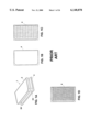
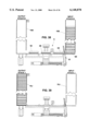
- a perspective view of a microplate 1 is shown in FIG. 1A.
- Microplate 1 has microplate lid 2 and microplate base 4.
- Microplate 1 shown in FIGS. 1A and 1B has just one well.
- FIG. 1C shows a microplate with 96 wells in its base 4
- FIG. 1D shows a microplate with 384 wells in its base 4.
- Microplates with 1536 wells are also available.
- microplates are commonly filled with various media.
- the media can be either in a liquid form or have a thicker, viscous consistency, such as that found in Agar. It is very important to the efficient productivity of a laboratory to be able to pour media into microplates accurately and rapidly.
- an automated machine can provide the required throughput much faster than a technician can.
- Thermo Vision, Inc. with offices in Grand Junction, Colo., makes an automated filling machine that can only handle ten plates at a time and must be monitored continuously to remove filled plates and add new ones.
- Zymark Corp. with offices in Hopkinton, Mass., produces a liquid handling workstation, but it is also for low capacity runs and requires constant supervision.
- a automated filling machine is known that has slightly greater capacity than those made by Thermo Vision and Zymark Corp., but the increased capacity is limited on the input side and there is no restacking capability. This means that there has to be a technician present at all times to remove filled plates and make room for the new ones.
- This machine also uses an expensive robot for positioning. The robot adds extra cost to the device.
- CCS Packard with offices in Torrance, Calif., produces a couple of machines that include both an input and an output chamber that can hold up to 50 plates. These devices rely on a conveyor system.
- U.S. Pat. No. 5,415,060 discloses a device in which a bridge that aligns and holds steady a hand-held liquid dispenser means is positioned over microplate holder for a manual application of liquid. Although this device may be considerably less expensive than prior art automated devices, it is too slow and impractical for many laboratories.
- the present invention provides an automated machine for filling a plurality of microplates.
- the automated machine includes at least one input stacking chamber for stacking empty microplates, at least one output stacking chamber for stacking filled microplates, and a microplate filling assembly disposed between the at least one input stacking chamber and the at least one output stacking chamber.
- the microplate filling assembly has: (1) an input chamber lifting mechanism for periodically lifting all microplates but the bottom microplate in the at least one input stacking chamber, (2) a linear actuator, (3) a walking beam indexer attached to the linear actuator, driven by the linear actuator and positioned to move microplates from the at least one input stacking chamber to the at least one output stacking chamber, (4) a lid lifter attached to the linear actuator, for lifting the lid off of each microplate to permit the microplate to be filled, and after filling to replace the lid, (5) a nozzle in communication with a media source and positioned to fill the microplates after their lids have been lifted off, and (6) an output chamber lifting mechanism for lifting all filled microplates in the at least one output stacking chamber to provide a space for recently filled microplates to be moved to a bottom position in the at least one stacking chamber.
- FIG. 1A shows a perspective view of a single-well microplate.
- FIG. 1B shows a top view of a single-well microplate base.
- FIG. 1C shows a top view of a 96-well microplate base.
- FIG. 1D shows a top view of a 384-well microplate base.
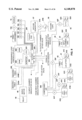
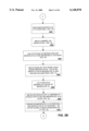
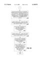
- FIGS. 2A-2D are a flowchart representing the programming for the programmable logic controller.
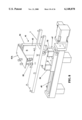
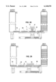
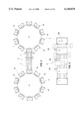
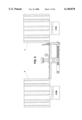
- FIG. 3 shows a top view of a preferred embodiment of the present invention.
- FIG. 4 shows a top view of the microplate filling assembly.
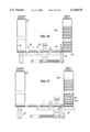
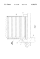
- FIG. 5 shows a side view of a preferred embodiment of the present invention.
- FIG. 6 shows a perspective view of the input chamber singulator.
- FIG. 7 shows a detailed view of the input chamber singulator lifting input stack A.
- FIG. 8 shows a perspective view of the lid lifter and walking beam indexer.
- FIG. 9 shows a block diagram of the programmable logic controller other components of a preferred embodiment of the present invention.
- FIGS. 10-39 show a sequence depicting the operation of a preferred embodiment of the present invention.
- FIG. 3 shows input carousel 3 and output carousel 5 connected by microplate filling assembly 6.
- empty microplates are stacked into input carousel 3, automatically filled with media via microplate filling assembly 6, and automatically restacked into output carousel 5.
- input carousel 3 has ten input chambers 15A-15J and output carousel 5 has ten output chambers 16A-16J.
- Each input chamber 15 and output chamber 16 is capable of receiving and holding a stack of twenty-four microplates. Therefore, a total of 240 empty microplates may be stacked in input carousel 3, automatically filled via microplate filling assembly 6, and automatically restacked into output carousel 5.
- FIG. 4 shows a detailed top view of microplate filling assembly 6 with microplates located at positions ⁇ - ⁇ along microplate filling assembly 6.
- FIGS. 10-39 illustrate the sequence of operation of a preferred embodiment of the present invention.
- FIGS. 2A-2E show a flowchart representing preferred programming of PLC 200 and corresponds with the sequence illustrated in FIGS. 10-34.
- PLC 200 automatically conducts a start up routine. In this routine, PLC 200 checks all PLC 200 controlled components, homes all pneumatic devices and checks all sensors. If there are any errors (for example, jammed microplates or component malfunction), the user will be alerted via monitor 204 (FIG. 9).
- PLC 200 checks all PLC 200 controlled components, homes all pneumatic devices and checks all sensors. If there are any errors (for example, jammed microplates or component malfunction), the user will be alerted via monitor 204 (FIG. 9).
- step 1010 the user inputs the type of microplate that he wants to be filled (i.e., either a single-well, 96-well, or 384-well microplate). As shown in step 1015, because the nozzle type varies depending on the microplate selected, the user must install the correct nozzle. Depending upon the microplate selected by the user in the start up routine, PLC 200 selects walking beam indexer 7 positioning data and nozzle 13 fill rate.
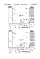
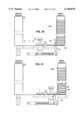
- FIG. 10 shows a stack of twenty-four empty microplates 1A-24A loaded into input chamber 15A.
- Microplate 1A is at the bottom at position ⁇ (FIG. 4) and microplate 2A is directly above microplate 1A.
- Microplate 24A is at the top of the stack.
- output stack A located inside output chamber 16A is empty with no microplates.
- walking beam indexer 7 has lowered so that dowel pins 14 are below the horizontal plane formed by the top surface of beam 8.
- input chamber singulator 23 has lifted input stack A2-A24 at microplate 2A.
- Microplate 1A is left at position ⁇ , as shown in FIG. 4.
- a detailed view of input chamber singulator 23 lifting input stack A is seen in FIG. 7.
- Tab singulator 33 lifts microplate 2A allowing a small gap to form between microplate 1A and 2A. Since input stack A2-A24 is confined on all sides by input chamber 15A, instead of tilting input stack A2-A24, lifting from the front edge lifts the entire stack vertically. Also as shown in FIG. 12, walking beam indexer 7 has moved to the right.
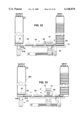
- walking beam indexer 7 is raised so that dowel pin 14 is located directly behind microplate 1A.
- walking beam indexer 7 has moved to the left pushing microplate 1A to position ⁇ (see FIG. 4) from the bottom of the stack.
- walking beam indexer 7 has been lowered so that dowel pins 14 are below the horizontal plane formed by the top surface of beam 8.
- Input chamber singulator 23 has dropped input stack A.
- Microplate 1A is at position ⁇ and microplate 2A is at position ⁇ .
- walking beam indexer 7 has moved to the right.
- Input chamber singulator 23 has lifted input stack A3-A24, leaving behind microplate 2A at position ⁇ .
- lid lifter 41 has dropped to the top of microplate lid 2 of microplate 1A, has grasped microplate lid 2 with a vacuum force and will lift microplate lid 2 prior to the display shown in FIG. 18.
- Walking beam indexer 7 is raised so that dowel pin 14 is located directly behind microplate 2A.
- lid lifter 41 has lifted microplate lid 2 off of microplate 1A.
- Walking beam indexer 7 has moved microplate base 4 of microplate 1A to the left underneath nozzle 13. If single well plates are being used as shown in FIGS. 1A and 1B, walking beam indexer 7 will move microplate 1A to a center location to fill microplate 1A with media. If microplate 1A is a multi-welled microplate (for example, a 96 or 384-welled plate), walking beam indexer 7 will first move microplate 1A to so that the first row is underneath nozzle 13. After the first row is filled, walking beam indexer 7 will move microplate 1A to the left so that the second row is underneath nozzle 13 so that it can be filled. Walking beam indexer 7 will continue to move microplate 1A incrementally in this manner until all rows are filled. As shown in FIG. 18, microplate lid 2 is being held directly over microplate base 4 by lid lifter 41.
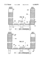
- input chamber singulator 23 has dropped input stack A.
- Lid lifter 41 has been raised.
- Microplate 1A is at position ⁇ (FIG. 4)
- microplate 2A is at position ⁇
- microplate 3A is at position ⁇ .
- Walking beam indexer 7 has been lowered so that dowel pins 14 are below the horizontal plane formed by the top surface of beam 8.
- walking beam indexer 7 has moved to the right.
- Input chamber singulator 23 has lifted input stack A4-A24, leaving behind microplate 3A at position ⁇ .
- lid lifter 41 has dropped to the top of microplate lid 2 of microplate 2A, has grasped microplate lid 2 with a vacuum force and will lift microplate lid 2 prior to the display shown in FIG. 23.
- Walking beam indexer 7 is raised so that dowel pin 14 is located directly behind microplate 3A.
- lid lifter 41 has lifted microplate lid 2 off of microplate 2A. Walking beam indexer 7 and lid lifter 41 have moved to the left. Microplate base 4 of microplate 2A is underneath nozzle 13 and is being filled with media 11. Microplate lid 2 is being held directly over microplate base 4 by lid lifter 41.
- input chamber singulator 23 has dropped input stack A.
- Lid lifter 41 has been raised.
- Walking beam indexer 7 has been lowered so that dowel pins 14 are below the horizontal plane formed by the top surface of beam 8.
- walking beam indexer 7 has moved to the right.
- Input chamber singulator 23 has lifted input stack A5-A24, leaving behind microplate 4A at position ⁇ .
- lid lifter 41 has dropped to the top of microplate lid 2 of microplate 3A, has grasped microplate lid 2 with a vacuum force and will lift microplate lid 2 prior to the display shown in FIG. 28.
- Walking beam indexer 7 is raised so that dowel pin 14 is located directly behind microplate 4A.
- lid lifter 41 has lifted microplate lid 2 off of microplate 3A. Walking beam indexer 7 and lid lifter 41 have moved to the left. Microplate base 4 of microplate 3A is underneath nozzle 13 and is being filled with media 11. Microplate lid 2 is being held directly over microplate base 4 by lid lifter 41. Microplate 1A is being moved inside of output chamber 16A.
- microplate 1A is at position ⁇
- microplate 2A is at position ⁇
- microplate 3A is at position ⁇
- microplate 4A is at position ⁇ (FIG. 4).
- Microplate 3A has been filled with media 11.
- input chamber singulator 23 has dropped input stack A.
- Lid lifter 41 has been raised.
- Walking beam indexer 7 has been lowered so that dowel pins 14 are below the horizontal plane formed by the top surface of beam 8.
- walking beam indexer 7 has moved to the right.
- Input chamber singulator 23 has lifted input stack A6-A24, leaving behind microplate 5A at position ⁇ .
- lid lifter 41 has dropped to the top of microplate lid 2 of microplate 4A, has grasped microplate lid 2 with a vacuum force and will lift microplate lid 2 prior to the display shown in FIG. 33.
- Walking beam indexer 7 is raised so that dowel pin 14 is located directly behind microplate 5A.
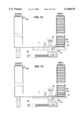
- Output chamber lifter 61 has lifted microplate 1A to allow room for microplate 2A to be restacked from the bottom.
- lid lifter 41 has lifted microplate lid 2 off of microplate 4A. Walking beam indexer 7 and lid lifter 41 have moved to the left. Microplate base 4 of microplate 4A is underneath nozzle 13 and is being filled with media 11. Microplate lid 2 is being held directly over microplate base 4 by lid lifter 41. Output chamber lifter cylinder 61A has dropped allowing room for microplate 2A to enter output chamber 16A. Microplate 1A is resting on output chamber lifter cylinder 61B and microplate 2A.
- FIG. 34 walking beam indexer 7 has moved further to the left.
- Lid lifter 41 has returned microplate lid 2 of microplate 4A to microplate base 4.
- Microplate 2A is at position ⁇
- microplate 3A is at position ⁇
- microplate 4A is at position ⁇
- microplate 5A is at position ⁇ (FIG. 4).
- Microplate 3A has been filled with media 11.
- Output chamber lifter cylinder 61B has dropped and microplate 1A is resting on microplate 2A inside output chamber 16A.
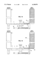
- FIG. 35 shows a stack of twenty-one filled microplates loaded into output chamber 16A.
- Microplate 1A is at the top of output stack A and microplate 2A is directly underneath microplate 1A.
- Microplate 21A is at the bottom of output stack A at position ⁇ .
- Microplate 22A is at postion ⁇ , microplate 23A is at position ⁇ , and microplate 24A is at position ⁇ .
- Input stack A is empty with no microplates.
- FIG. 36 shows a stack of twenty-four empty microplates 1B-24B loaded into input chamber 15B.
- Microplate 1B is at the bottom at position ⁇ (FIG. 4) and microplate 2B is directly above microplate 1B.
- Microplate 24B is at the top of the stack.
- Microplate 21A is at the bottom of output stack A at position ⁇ .
- Microplate 22A is at postion ⁇ , microplate 23A is at position ⁇ , and microplate 24A is at position ⁇ .
- Lid lifter 41 has been raised. Walking beam indexer 7 has been lowered so that dowel pins 14 are below the horizontal plane formed by the top surface of beam 8.
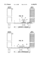
- FIG. 37 shows microplate 1A at the top of output stack A.
- Microplate 24A is at the bottom of output stack A at position ⁇ .
- Microplate 1B is at position ⁇ , microplate 2B is at position ⁇ , and microplate 3B is at position ⁇ .
- output carousel 5 rotates so that output stack B inside output chamber 16B is aligned with microplate filling assembly 6, as shown in FIG. 38.
- FIG. 38 shows microplate 1B at position ⁇ , microplate 2B at position ⁇ , and microplate 3B at position ⁇ .
- Input chamber singulator 23 has dropped input stack B and microplate 4B is at position ⁇ .
- FIG. 39 shows an empty input chamber 15J and an output chamber 16J that has a full output stack J with filled microplates. If the operator desires, empty input chambers 15 from input carousel 3 can be reloaded with empty microplates while the machine is in operation, and it will continue to run.
- Sensors 100 and 104 (FIGS. 4 and 37) and sensors 101, 102 and 103 (FIG. 4) continuously check for microplate presence. If there are no microplates in input carousel 3, this is recognized as an error and the process is stopped until more microplates are added to the system and the machine is restarted. The same is true for output carousel 5. If all 240 positions are filled in output carousel 5, the machine will recognize this as an error and will not continue until output chambers 16A-16J are emptied and the machine is restarted. If input carousel 3 is empty but sensors 101 though 103 report there are still microplates present in fill assembly 6 and sensor 104 reports there is still room in output carousel 5, the process will continue until all microplates are restacked in output carousel 5.
- input carousel 3 and output carousel 5 are fabricated from 0.060 thick 304 stainless steel.
- Base 17 (FIG. 3) has a diameter of approximately 16 inches.
- Input carousel 3 has 10 input chambers 15 mounted to base 17.
- output carousel 5 has ten output chambers 16 mounted to base 17.
- Input chambers 15 and output chambers 16 are approximately 16.5 inches tall, have a depth of approximately 3.400 inches and are approximately 5.063 inches wide.
- Each input chamber 15 and output chamber 16 can hold twenty-four microplates 1. Chambers 15 and 16 are fabricated so that microplates 1 fit snuggly inside, but are able to slide freely up and down, as shown in FIG. 3. Chambers 15 and 16 are rigidly mounted to base 17 with mounting plates 19.
- indexing tables 210A and 210B are manufactured by Kamo Seiko, Inc. and supplied by Land Sea, Inc. Indexing Tables 210A and 210B function to rotate input carousel 3 and output carousel 5 to ten different positions each so that each input chamber 15 and output chamber 16 can be directly aligned with walking beam indexer 7. As shown in FIG. 3, input chamber 15A and output chamber 16A are directly aligned with walking beam indexer 7.
- FIG. 6 A detailed perspective view of a preferred embodiment of input chamber singulator 23 is shown in FIG. 6.
- Pneumatic cylinder 25 is pivotally mounted to bracket 27.
- pneumatic cylinder 25 is a double acting/single rod pneumatic cylinder (part no. NCDJ2D04OOHB) manufactured by SMC, Inc.
- Link singulator 29 is pivotally mounted to pneumatic cylinder 25 and rigidly connected to rod singulator 31.
- Rod singulator 31 is mounted to singulator bearing blocks 35 and is free to rotate on plastic flange bearings 37.
- Tab singulators 33 are rigidly mounted to rod singulator 31.
- Bearing blocks 35 are rigidly mounted to supports 39, as shown in FIG. 6 and FIG. 10.
- FIG. 12 shows pneumatic cylinder 25 in its retracted position with tab singulators 33 lifting microplate 2A.
- a detailed side view of tab singulator 33 lifting input stack A is shown in FIG. 7. Note that the triangular shape of tab singulators 33 (FIG. 6) corresponds to 45° recess 2A in microplates 1 (FIG. 1). Therefore, tab singulator 33 is able to lift input stack A without bumping into microplate lid 2, as shown in FIG. 7.
- FIG. 8 shows a perspective view of walking beam indexer 7 and lid lifter 41.
- Lid lifter 41 is rigidly mounted to lid lifter brackets 43.
- Lid Lifter brackets is rigidly connected to linear actuator threaded connector 47 (FIGS. 8 and 10).
- Linear actuator threaded connector is threaded onto lead screw 49 of linear actuator 45.
- linear actuator 45 is an actuated linear motion system (part no. LC332001A-3001-P10) manufactured and available from Bearing Engineers, Inc.
- Lead screw 49 is actuated via servo motor 48.
- servo motor 48 is an animatics motor (part no. SM2310) with amplifier and encoder all in one package
- Walking beam indexer 7 is mounted to compact pneumatic cylinders 52.
- pneumatic cylinders 52 expand, walking beam indexer 7 is raised, as shown in FIG. 10.
- pneumatic cylinders 52 retract, walking beam indexer 7 is lowered, as shown in FIG. 11.
- compact cylinders are part number NCDQ2B20-10D-J79L manufactured by SMC and supplied by A&H Sales.
- Pneumatic cylinder 53 is rigidly mounted to the back of indexer bracket 43, as shown in FIG. 8.
- pneumatic cylinder 53 is a dual rod pneumatic cylinder (part no. CXSM-15-50-Y59B) manufactured by SMC, Inc. and available from A&H Sales.
- Lid lifter top 41A is rigidly connected to the top of pneumatic cylinder 53.
- Vacuum cups 55 extend downward from lid lifter top 41A. Vacuum lines connect vacuum cups 55 to vacuum generator 57, as shown in FIG. 9.
- Linear actuator servo motor 48 (FIG. 10) rotates lead screw 49.
- linear actuator threaded connector 47 moves horizontally back and forth. Consequently, indexer bracket 43 moves horizontally back and forth. As it does so, it changes the horizontal location of both walking beam indexer 7 and lid lifter 41 together with an accuracy of plus or minus 0.0001 inches.
- output chamber lifter 61 includes pneumatic cylinders 61A and 62A rigidly attached to bracket 62.
- pneumatic cylinders 61A and 61B are dual rod pneumatic cylinders (part no. CXSM-15-50-Y59B) manufactured by SMC, Inc. and available from A&H Sales.
- output chamber lifter 61 functions to lift microplate 1A up while microplate 2A is inserted into output chamber 16A.
- PLC Programmable Logic Controller
- FIG. 9 depicts a block diagram of Programmable Logic Controller (PLC) 200 and other components of a preferred embodiment of the present invention.
- PLC 200 includes CPU 201 with associated memory (RAM 202, and ROM 203).
- Input/output port 205 connects PLC 200 with other components of the present invention.
- a user of the present invention can monitor the status of the operation of the present invention by way of monitor 204.
- Input chamber singulator 23 can be in the drop position as shown in FIG. 11 or in the lift position as shown in FIG. 12.
- the drop position is to lower input stack A so that the bottommost microplate (microplate 1A) is at position ⁇ .
- the lift position is to lift input stack A (except for microplate 1A) off of microplate 1A so that microplate 1A can then be removed from the bottom.
- two way solenoid valve 23F (FIG. 9) is in the open position and the rod in cylinder 25 of input singulator 23 is fully extended.
- PLC 200 sends an electric signal to return solenoid valve 23F to the closed position. This allows compressed air to enter cylinder 25 above its internal piston and the air below the piston is allowed to escape, causing the rod in pneumatic cylinder 25 to retract, as shown in FIG. 12.
- pneumatic retraction sensor 23D will send an electric signal to PLC 200 indicating the movement has been completed.
- PLC 200 sends an electric signal to open two way solenoid valve 23F (FIG. 9). This allows compressed air from compressed air source 250 to flow into pneumatic cylinder 25 below the internal piston and air above the piston is allowed to escape through an exhaust manifold, which causes the the rod in the cylinder to extend, as shown in FIG. 11.
- pneumatic extension sensor 21C will send an electric signal to PLC 200 indicating the move has been completed.
- Pneumatic cylinder 53 raises and lowers lid lifter 41.
- Lid lifter 41 is lowered so that the vacuum cups can rest on microplate lid 2, as shown in FIG. 17.
- Lid lifter 41 is raised so that it can lift microplate lid of microplate base 4 as shown in FIG. 18.
- lid lifter 41 is in the fully extended position with two-way solenoid valve 41F open.
- PLC 200 sends an electric signal to close two-way solenoid valve 41F. This allows compressed air below the internal piston inside pneumatic cylinder 53 to escape while allowing air to enter above the piston, causing the rod in pneumatic cylinder 53 to retract. This causes lid lifter 41 to drop, as shown in FIG. 17.
- pneumatic retraction sensor 41D will send an electric signal to PLC 200 indicating the movement has been completed.
- PLC 200 sends an electric signal to open the two-way solenoid valve 41F (FIG. 9). This allows compressed air from compressed air source 250 to flow into pneumatic cylinder 53 below the piston and allows air above the piston to escape through the exhaust manifold, causing it to extend. This causes lid lifter 41 to raise, as shown in FIG. 18.
- pneumatic cylinder 53 is fully extended pneumatic extension sensor 41C will send an electric signal to PLC 200 indicating the movement has been completed.
- Output chamber lifter 61 can be fully lowered (as shown in FIG. 31), fully raised (as shown in FIG. 32), or pneumatic cylinder 61A can be lowered while pneumatic cylinder 61B is raised (as shown in FIG. 33).
- the lowered position is to allow microplate 1A to slide into output chamber 16A and the raised position is to lift microplate 1A so that microplate 2A to enter output chamber 16A.
- the position where the rod in pneumatic cylinder 61A is lowered while the rod in pneumatic cylinder 61B is raised is to allow microplate 2A to provide support for microplate 1A while microplate 2A enters further into output chamber 16A.
- the procedure to raise and lower output chamber lifter pneumatic cylinder 61A is identical to the procedure to raise and lower output chamber lifter pneumatic cylinder 61B.
- PLC 200 sends an electric signal to open two-way solenoid valve 61F. This allows compressed air from compressed air source 250 to flow into output chamber lifter pneumatic cylinder 61A below the internal piston and allows air above the piston to escape, which causes it to extend.
- pneumatic extension sensor 61C will send an electric signal to PLC 200 indicating the movement has been completed.
- PLC 200 sends an electric signal to close two-way solenoid valve 61F. This allows compressed air to enter output chamber lifter pneumatic cylinder 61A above the piston and allows the air below the piston to escape, causing the rod in output chamber lifter pneumatic cylinder 61A to retract. When the rod in output chamber lifter pneumatic cylinder 61A is fully retracted pneumatic retraction sensor 61D will send an electric signal to PLC 200 indicating the movement has been competed.
- Walking beam indexer 7 is attached to compact pneumatic cylinders 52, as shown in FIG. 14. Walking beam indexer 7 can be raised (as shown in FIG. 14), or lowered (as shown in FIG. 15). Walking beam indexer 7 is raised in order to permit dowel pins 14 to push microplate 1A, as shown in FIG. 14. Walking beam indexer 7 is lowered so that as it moves from left to right, dowel pins 14 do not contact microplate 1A, as shown in FIGS. 15-16.
- PLC 200 sends an electric signal to open two-way solenoid valve 52F. This allows compressed air from compressed air source 250 to flow into compact pneumatic cylinder 52 below the internal piston and allows air above the piston to escape, which causes it to extend.
- pneumatic extension sensor 52C will send an electric signal to PLC 200 indicating the movement has been completed.
- PLC 200 sends an electric signal to close two-way solenoid valve 52F. This allows compressed air to enter compact pneumatic cylinder 52 above the piston and allows the air below the piston to escape, causing the rod in compact pneumatic cylinder 52 to retract.
- pneumatic retraction sensor 52D When the rod in compact pneumatic cylinder 52 is fully retracted pneumatic retraction sensor 52D will send an electric signal to PLC 200 indicating the movement has been competed.
- a preferred embodiment of the present invention has a variety of sensors that PLC 200 utilizes to conduct error checks.
- sensor 100 is located beneath position ⁇ to verify a microplate is present at position ⁇ .
- sensor 101 verifies microplate placement at position ⁇
- sensor 102 verifies microplate placement at position ⁇
- sensor 103 verifies microplate placement at position ⁇
- sensor 104 verifies microplate placement at the top of output chamber 16A, as shown in FIG. 10.
- Sensors 100 and 104 are photoelectric switches (part no. EQ-22-PN-J) supplied by Clayton Controls, and manufactured by SUNX. These sensors work by emitting a beam of light and switch "on" when the beam is blocked at a certain distance from the emitter.
- Sensors 101, 102, 103 are also photoelectric sensors (part number EX-14A-PN manufactured by SUNX and supplied by Clayton Controls).
- each pneumatic component (input chamber singulator 23, lid lifter 41, output chamber lifter pneumatic cylinders 61A and 61B, and compact pneumatic cylinders 52) has two sensors: one that transmits an electrical signal when the component is fully extended (pneumatic extension sensors 61C, 41C, 23C, and 52C) and another sensor when it is fully retracted (pneumatic retraction sensors 61D, 41D, 23D, and 52D).
- Linear actuator servo motor 48 includes a motor relay 50. If linear actuator servo motor 48 is jammed or malfunctioning, motor relay 50 will report an error to PLC 200 which will be displayed on monitor 204.
- PLC 200 is programmed to check its sensors continuously. It will check to verify that the microplates have correctly been moved to their appropriate positions, that linear actuator servo motor 48 is not jammed or malfunctioning, and that the pneumatic components have correctly extended or retracted.
- PLC 200 is Ethernet compatible and will allow the invention to be monitored for errors and throughput from another computer.
- Applicants have built and tested a prototype model of the preferred embodiment of the present invention. During a dry run (i.e., not actually filling microplates with media), Applicants observed that the prototype model successfully moved six hundred microplates from input carousel 3 to output carousel 5 in one hour. This rate for moving microplates greatly exceeds that of the closest prior art. It should be noted that when filling microplates, the performance rate will vary depending on the type of microplate (i.e. single-well or multi-well) and on the type of media (i.e., Agar or liquid).
- Microplate filling assembly 6 (FIGS. 3-4) would remove empty microplates from input chamber 15, fill them and then restack them in output chamber 16 utilizing the process shown in FIGS. 10-35. Also, although it was previously described how a user of the present invention would stack empty microplates inside of input chamber 15, it would also be possible to save time by attaching pre-stacked input chambers 15 containing empty microplates onto input carousel 3.
Abstract
Description
Claims (19)
Priority Applications (3)
| Application Number | Priority Date | Filing Date | Title |
|---|---|---|---|
| US09/411,943 US6148878A (en) | 1999-10-04 | 1999-10-04 | Automated microplate filling device and method |
| US09/699,818 US6979425B1 (en) | 1999-10-04 | 2000-10-30 | High capacity microarray dispensing |
| US09/702,164 US6360792B1 (en) | 1999-10-04 | 2000-10-30 | Automated microplate filling device and method |
Applications Claiming Priority (1)
| Application Number | Priority Date | Filing Date | Title |
|---|---|---|---|
| US09/411,943 US6148878A (en) | 1999-10-04 | 1999-10-04 | Automated microplate filling device and method |
Related Parent Applications (1)
| Application Number | Title | Priority Date | Filing Date |
|---|---|---|---|
| US09/611,256 Continuation-In-Part US6558623B1 (en) | 1999-10-04 | 2000-07-06 | Microarray dispensing with real-time verification and inspection |
Related Child Applications (2)
| Application Number | Title | Priority Date | Filing Date |
|---|---|---|---|
| US09/699,818 Continuation-In-Part US6979425B1 (en) | 1999-10-04 | 2000-10-30 | High capacity microarray dispensing |
| US09/702,164 Continuation-In-Part US6360792B1 (en) | 1999-10-04 | 2000-10-30 | Automated microplate filling device and method |
Publications (1)
| Publication Number | Publication Date |
|---|---|
| US6148878A true US6148878A (en) | 2000-11-21 |
Family
ID=23630918
Family Applications (1)
| Application Number | Title | Priority Date | Filing Date |
|---|---|---|---|
| US09/411,943 Expired - Lifetime US6148878A (en) | 1999-10-04 | 1999-10-04 | Automated microplate filling device and method |
Country Status (1)
| Country | Link |
|---|---|
| US (1) | US6148878A (en) |
Cited By (40)
| Publication number | Priority date | Publication date | Assignee | Title |
|---|---|---|---|---|
| US6325114B1 (en) * | 2000-02-01 | 2001-12-04 | Incyte Genomics, Inc. | Pipetting station apparatus |
| US20020009391A1 (en) * | 1999-05-03 | 2002-01-24 | Ljl Biosystems, Inc. | Integrated sample-processing system |
| US6360792B1 (en) * | 1999-10-04 | 2002-03-26 | Robodesign International, Inc. | Automated microplate filling device and method |
| US6368872B1 (en) * | 1999-10-22 | 2002-04-09 | Tecan Trading Ag | Apparatus and method for chemical processing |
| US6395231B1 (en) * | 1997-10-21 | 2002-05-28 | Cybio Instruments Gmbh | Pipette and handling automatic machine for microtitration plates with permeable bases |
| US20020143153A1 (en) * | 1999-06-18 | 2002-10-03 | Santarsiero Bernard D. | Mother liquor fluid delivery apparatus |
| US20020176803A1 (en) * | 2001-05-25 | 2002-11-28 | Hamel Marc F. | Automated pipetting system |
| US6495369B1 (en) * | 1998-08-10 | 2002-12-17 | Caliper Technologies Corp. | High throughput microfluidic systems and methods |
| US6514750B2 (en) * | 2001-07-03 | 2003-02-04 | Pe Corporation (Ny) | PCR sample handling device |
| US20030044991A1 (en) * | 2001-09-06 | 2003-03-06 | Genetix Limited | Apparatus for and methods of handling biological sample containers |
| US20030044321A1 (en) * | 2001-09-06 | 2003-03-06 | Haslam James Keith | Apparatus for and methods of handling biological sample containers |
| US20030134428A1 (en) * | 2002-01-14 | 2003-07-17 | Shanler Michael S. | Pin tool apparatus and method |
| US6645431B2 (en) * | 2001-01-22 | 2003-11-11 | Thomas W. Astle | Apparatus for automated magnetic separation of materials in laboratory trays |
| US6699437B1 (en) * | 2000-08-29 | 2004-03-02 | Thomas W. Astle | Bioassay cassette with memory and method of use |
| WO2004028683A1 (en) * | 2002-09-27 | 2004-04-08 | Arrayjet Limited | Method and apparatus for substrate handling and printing |
| US6739448B1 (en) | 2000-02-01 | 2004-05-25 | Incyte Corporation | Method and apparatus for shuttling microtitre plates |
| US20040187958A1 (en) * | 2003-01-17 | 2004-09-30 | Jean-Pascal Viola | Pre-filled crystallization plates and methods for making and using same |
| US20040206419A1 (en) * | 2000-10-30 | 2004-10-21 | Ganz Brian L. | Automated storage and retrieval device and method |
| US6825042B1 (en) * | 1998-02-24 | 2004-11-30 | Vertex Pharmaceuticals (San Diego) Llc | Microplate lid |
| US20050019904A1 (en) * | 2003-06-05 | 2005-01-27 | Zarur Andrey J. | Apparatus and method for manipulating substrates |
| WO2005016526A2 (en) * | 2003-08-04 | 2005-02-24 | Irm, Llc | Multi-well container positioning devices and related systems and methods |
| US20050070010A1 (en) * | 2001-12-11 | 2005-03-31 | Thomas Laurell | Dockable processing module |
| US20050074360A1 (en) * | 2003-10-02 | 2005-04-07 | Dewalch Binz | High throughput sample preparation |
| US6893611B1 (en) * | 1998-03-20 | 2005-05-17 | Fondation Jean Dausset-Ceph | Automatic device for dispensing samples in liquid medium for use in chemical or biological reactions |
| US20050124925A1 (en) * | 2003-05-23 | 2005-06-09 | Yvette Scherpenborg | Thermal compressive aerating bandage and methods of use relating to same |
| EP1552266A1 (en) * | 2002-09-26 | 2005-07-13 | BioPath Automation, L.L.C. | Apparatus and methods for automated handling and embedding of tissue samples |
| US7158888B2 (en) | 2001-05-04 | 2007-01-02 | Takeda San Diego, Inc. | Determining structures by performing comparisons between molecular replacement results for multiple different biomolecules |
| US20070104618A1 (en) * | 2003-10-17 | 2007-05-10 | Biopath Automation, L.L.C. | Cassette for handling and holding tissue samples during processing, embedding and microtome procedures, and methods therefor |
| US20070172396A1 (en) * | 2006-01-23 | 2007-07-26 | Neeper Robert K | Automated system for storing, retrieving and managing sample |
| US20070207450A1 (en) * | 2003-06-05 | 2007-09-06 | Bioprocessors Corp. | System and method for process automation |
| WO2008069161A1 (en) * | 2006-11-27 | 2008-06-12 | Panasonic Corporation | Dispenser |
| US7416710B1 (en) | 2003-12-31 | 2008-08-26 | Takeda San Diego, Inc. | Method and system for performing crystallization trials |
| US7776274B2 (en) | 2002-09-26 | 2010-08-17 | Biopath Automation, L.L.C. | Cassette and embedding assembly for handling and holding tissue samples during processing, embedding and microtome procedures, staging devices therefore, and methods therefor |
| US8329120B2 (en) | 2009-01-22 | 2012-12-11 | Biopath Automation, L.L.C. | Microtome sectionable biopsy support for orienting tissue samples |
| US8383067B2 (en) | 2006-12-12 | 2013-02-26 | Biopath Automation, L.L.C. | Biopsy support with sectionable resilient cellular material |
| US8591832B2 (en) | 2011-01-28 | 2013-11-26 | Integra Biosciences Corp. | Multi-channel wellplate filling system |
| CN110168382A (en) * | 2016-12-23 | 2019-08-23 | 英派克控股有限公司 | Liquid treatment equipment |
| US11175298B2 (en) | 2006-01-23 | 2021-11-16 | Brooks Automation, Inc. | Automated system for storing, retrieving and managing samples |
| CN114522747A (en) * | 2022-04-19 | 2022-05-24 | 翊新诊断技术(苏州)有限公司 | Micro nanoliter sample application device |
| CN114806845A (en) * | 2022-05-27 | 2022-07-29 | 丁烁 | Public health preventive medicine bacterium collection detection system and use method thereof |
Citations (4)
| Publication number | Priority date | Publication date | Assignee | Title |
|---|---|---|---|---|
| US5415060A (en) * | 1992-09-04 | 1995-05-16 | Destefano, Jr.; Albert M. | Incremental advance means |
| US5772966A (en) * | 1997-01-24 | 1998-06-30 | Maracas; George N. | Assay dispensing apparatus |
| US5865224A (en) * | 1996-12-20 | 1999-02-02 | Life Technologies, Inc. | Method and apparatus for automated dispensing |
| US5988236A (en) * | 1998-07-31 | 1999-11-23 | Gilson, Inc. | Multiple syringe pump assembly for liquid handler |
-
1999
- 1999-10-04 US US09/411,943 patent/US6148878A/en not_active Expired - Lifetime
Patent Citations (4)
| Publication number | Priority date | Publication date | Assignee | Title |
|---|---|---|---|---|
| US5415060A (en) * | 1992-09-04 | 1995-05-16 | Destefano, Jr.; Albert M. | Incremental advance means |
| US5865224A (en) * | 1996-12-20 | 1999-02-02 | Life Technologies, Inc. | Method and apparatus for automated dispensing |
| US5772966A (en) * | 1997-01-24 | 1998-06-30 | Maracas; George N. | Assay dispensing apparatus |
| US5988236A (en) * | 1998-07-31 | 1999-11-23 | Gilson, Inc. | Multiple syringe pump assembly for liquid handler |
Cited By (99)
| Publication number | Priority date | Publication date | Assignee | Title |
|---|---|---|---|---|
| US6395231B1 (en) * | 1997-10-21 | 2002-05-28 | Cybio Instruments Gmbh | Pipette and handling automatic machine for microtitration plates with permeable bases |
| US6825042B1 (en) * | 1998-02-24 | 2004-11-30 | Vertex Pharmaceuticals (San Diego) Llc | Microplate lid |
| US6893611B1 (en) * | 1998-03-20 | 2005-05-17 | Fondation Jean Dausset-Ceph | Automatic device for dispensing samples in liquid medium for use in chemical or biological reactions |
| US6495369B1 (en) * | 1998-08-10 | 2002-12-17 | Caliper Technologies Corp. | High throughput microfluidic systems and methods |
| US7316801B2 (en) | 1998-08-10 | 2008-01-08 | Caliper Life Sciences, Inc. | High throughput microfluidic systems and methods |
| US20030017085A1 (en) * | 1998-08-10 | 2003-01-23 | Caliper Technologies Corp. | High throughput microfluidic systems and methods |
| US20020009391A1 (en) * | 1999-05-03 | 2002-01-24 | Ljl Biosystems, Inc. | Integrated sample-processing system |
| US6838051B2 (en) * | 1999-05-03 | 2005-01-04 | Ljl Biosystems, Inc. | Integrated sample-processing system |
| US6951575B2 (en) | 1999-06-18 | 2005-10-04 | The Regents Of The University Of California | Method for performing high density submicroliter crystallization experiments |
| US20030109065A1 (en) * | 1999-06-18 | 2003-06-12 | Santarsiero Bernard D. | High density crystallization experiment device |
| US7015041B2 (en) | 1999-06-18 | 2006-03-21 | The Regents Of The University Of California | Automated method for setting up multiple crystallization experiments in submicroliter volumes |
| US7001438B2 (en) | 1999-06-18 | 2006-02-21 | The Regents Of The University Of California | Method for performing submicroliter crystallization experiments with high experiment to experiment precision |
| US20020143153A1 (en) * | 1999-06-18 | 2002-10-03 | Santarsiero Bernard D. | Mother liquor fluid delivery apparatus |
| US6932845B2 (en) | 1999-06-18 | 2005-08-23 | The Regents Of The University Of California | Method for performing submicroliter crystallization experiments |
| US20030096293A1 (en) * | 1999-06-18 | 2003-05-22 | Santarsiero Bernard D. | Automated crystallization experiment setup apparatus comprising crystallization device identification code reader |
| US20030096294A1 (en) * | 1999-06-18 | 2003-05-22 | Santarsiero Bernard D. | Automated method for setting up crystallization experiments employing a crystallization device identification code reader |
| US20030109064A1 (en) * | 1999-06-18 | 2003-06-12 | Santarsiero Bernard D. | Automated crystallization experiment setup apparatus |
| US20020182637A1 (en) * | 1999-06-18 | 2002-12-05 | Santarsiero Bernard D. | Method for screening microcrystallizations for crystal formation |
| US20030109063A1 (en) * | 1999-06-18 | 2003-06-12 | Santarsiero Bernard D. | Automated crystallizationexperiment setup apparatus comprising sensor |
| US20030109046A1 (en) * | 1999-06-18 | 2003-06-12 | Santarsiero Bernard D. | Multiwell plate adapted for automated crystallization |
| US20030119048A1 (en) * | 1999-06-18 | 2003-06-26 | Santarsiero Bernard D. | Dispenser footprint greater than plate footprint |
| US6911056B2 (en) | 1999-06-18 | 2005-06-28 | The Regents Of The University Of California | Method for diffracting crystals formed by submicroliter crystallization experiments |
| US6360792B1 (en) * | 1999-10-04 | 2002-03-26 | Robodesign International, Inc. | Automated microplate filling device and method |
| US6368872B1 (en) * | 1999-10-22 | 2002-04-09 | Tecan Trading Ag | Apparatus and method for chemical processing |
| US6325114B1 (en) * | 2000-02-01 | 2001-12-04 | Incyte Genomics, Inc. | Pipetting station apparatus |
| US6739448B1 (en) | 2000-02-01 | 2004-05-25 | Incyte Corporation | Method and apparatus for shuttling microtitre plates |
| US6699437B1 (en) * | 2000-08-29 | 2004-03-02 | Thomas W. Astle | Bioassay cassette with memory and method of use |
| US7352889B2 (en) * | 2000-10-30 | 2008-04-01 | Ganz Brian L | Automated storage and retrieval device and method |
| US20040206419A1 (en) * | 2000-10-30 | 2004-10-21 | Ganz Brian L. | Automated storage and retrieval device and method |
| US6645431B2 (en) * | 2001-01-22 | 2003-11-11 | Thomas W. Astle | Apparatus for automated magnetic separation of materials in laboratory trays |
| US7158888B2 (en) | 2001-05-04 | 2007-01-02 | Takeda San Diego, Inc. | Determining structures by performing comparisons between molecular replacement results for multiple different biomolecules |
| US20020176803A1 (en) * | 2001-05-25 | 2002-11-28 | Hamel Marc F. | Automated pipetting system |
| WO2002096562A1 (en) | 2001-05-25 | 2002-12-05 | Matrix Technologies Corp. | Automated pipetting system |
| US6982063B2 (en) | 2001-05-25 | 2006-01-03 | Matrix Technologies Corp | Automated pipetting system |
| US6514750B2 (en) * | 2001-07-03 | 2003-02-04 | Pe Corporation (Ny) | PCR sample handling device |
| US6843962B2 (en) * | 2001-09-06 | 2005-01-18 | Genetix Limited | Apparatus for and methods of handling biological sample containers |
| US20030044321A1 (en) * | 2001-09-06 | 2003-03-06 | Haslam James Keith | Apparatus for and methods of handling biological sample containers |
| US6998094B2 (en) * | 2001-09-06 | 2006-02-14 | Genetix Limited | Apparatus for and methods of handling biological sample containers |
| US20030044991A1 (en) * | 2001-09-06 | 2003-03-06 | Genetix Limited | Apparatus for and methods of handling biological sample containers |
| US20050070010A1 (en) * | 2001-12-11 | 2005-03-31 | Thomas Laurell | Dockable processing module |
| US6827905B2 (en) | 2002-01-14 | 2004-12-07 | Becton, Dickinson And Company | Pin tool apparatus and method |
| US20030134428A1 (en) * | 2002-01-14 | 2003-07-17 | Shanler Michael S. | Pin tool apparatus and method |
| US8034292B2 (en) | 2002-09-26 | 2011-10-11 | Biopath Automation Llc | Apparatus and methods for automated handling and embedding of tissue samples |
| US7722810B2 (en) | 2002-09-26 | 2010-05-25 | Biopath Automation, Llc | Apparatus and methods for automated handling and embedding of tissue samples |
| EP1552266A1 (en) * | 2002-09-26 | 2005-07-13 | BioPath Automation, L.L.C. | Apparatus and methods for automated handling and embedding of tissue samples |
| US20050226770A1 (en) * | 2002-09-26 | 2005-10-13 | Biopath Automation, L.L.C. | Apparatus and methods for automated handling and embedding of tissue samples |
| US8734735B2 (en) | 2002-09-26 | 2014-05-27 | Biopath Automation, L.L.C. | Tissue cassette for automated handling and embedding of tissue samples |
| US7776274B2 (en) | 2002-09-26 | 2010-08-17 | Biopath Automation, L.L.C. | Cassette and embedding assembly for handling and holding tissue samples during processing, embedding and microtome procedures, staging devices therefore, and methods therefor |
| EP2322938A1 (en) * | 2002-09-26 | 2011-05-18 | BioPath Automation, L.L.C. | Apparatus and methods for automated handling and embedding of tissue samples |
| EP2998721A1 (en) * | 2002-09-26 | 2016-03-23 | BioPath Automation, L.L.C. | Apparatus and methods for automated handling and embedding of tissue samples |
| EP1552266A4 (en) * | 2002-09-26 | 2008-10-01 | Biopath Automation Llc | Apparatus and methods for automated handling and embedding of tissue samples |
| US20060153621A1 (en) * | 2002-09-27 | 2006-07-13 | Manning Howard J | Method and apparatus for substrate handling and printing |
| WO2004028683A1 (en) * | 2002-09-27 | 2004-04-08 | Arrayjet Limited | Method and apparatus for substrate handling and printing |
| US20040187958A1 (en) * | 2003-01-17 | 2004-09-30 | Jean-Pascal Viola | Pre-filled crystallization plates and methods for making and using same |
| US7514043B2 (en) | 2003-01-17 | 2009-04-07 | Nextal Biotechnologie Inc. | Pre-filled crystallization plates and methods for making and using same |
| US20050124925A1 (en) * | 2003-05-23 | 2005-06-09 | Yvette Scherpenborg | Thermal compressive aerating bandage and methods of use relating to same |
| US20070207450A1 (en) * | 2003-06-05 | 2007-09-06 | Bioprocessors Corp. | System and method for process automation |
| US20050019904A1 (en) * | 2003-06-05 | 2005-01-27 | Zarur Andrey J. | Apparatus and method for manipulating substrates |
| US7632675B2 (en) | 2003-06-05 | 2009-12-15 | Bioprocessors Corp. | Apparatus and method for manipulating substrates |
| WO2005016526A2 (en) * | 2003-08-04 | 2005-02-24 | Irm, Llc | Multi-well container positioning devices and related systems and methods |
| WO2005016526A3 (en) * | 2003-08-04 | 2005-07-14 | Irm Llc | Multi-well container positioning devices and related systems and methods |
| US20050118060A1 (en) * | 2003-08-04 | 2005-06-02 | Irm, Llc | Multi-well container positioning devices and related systems and methods |
| US20050074360A1 (en) * | 2003-10-02 | 2005-04-07 | Dewalch Binz | High throughput sample preparation |
| WO2005050158A3 (en) * | 2003-10-02 | 2008-06-19 | Dewalch Technologies Inc | High throughput sample preparation |
| US20100129259A1 (en) * | 2003-10-02 | 2010-05-27 | Dewalch Technologies, Inc. | High throughput sample preparation |
| WO2005050158A2 (en) * | 2003-10-02 | 2005-06-02 | Dewalch Technologies, Inc. | High throughput sample preparation |
| US8877146B2 (en) | 2003-10-17 | 2014-11-04 | Biopath Automation, L.L.C. | Cassette for handling and holding tissue samples during processing, embedding and microtome procedures, and methods therefor |
| US20070104618A1 (en) * | 2003-10-17 | 2007-05-10 | Biopath Automation, L.L.C. | Cassette for handling and holding tissue samples during processing, embedding and microtome procedures, and methods therefor |
| US7416709B1 (en) | 2003-12-31 | 2008-08-26 | Takeda San Diego, Inc. | Method for performing crystallization trials |
| US7435379B1 (en) | 2003-12-31 | 2008-10-14 | Takeda San Diego, Inc. | System for performing crystallization trials |
| US7452419B1 (en) | 2003-12-31 | 2008-11-18 | Takeda San Diego, Inc. | Method for performing crystallization trials |
| US7510690B1 (en) | 2003-12-31 | 2009-03-31 | Takeda San Diego, Inc. | System for performing crystallization trials |
| US7435397B1 (en) | 2003-12-31 | 2008-10-14 | Takeda San Diego, Inc. | System for performing crystallization trials |
| US7431768B1 (en) | 2003-12-31 | 2008-10-07 | Takeda San Diego, Inc. | System for performing crystallization trials |
| US7431769B1 (en) | 2003-12-31 | 2008-10-07 | Takeda San Diego, Inc. | Method for performing crystallization trials |
| US7416710B1 (en) | 2003-12-31 | 2008-08-26 | Takeda San Diego, Inc. | Method and system for performing crystallization trials |
| US20080044266A1 (en) * | 2006-01-23 | 2008-02-21 | Neeper Robert K | System and method for partitioning a temperature controlled compartment |
| US9702887B2 (en) | 2006-01-23 | 2017-07-11 | Brooks Automation, Inc. | Automated system for storing, retrieving and managing samples |
| US7648321B2 (en) | 2006-01-23 | 2010-01-19 | Nexus Biosystems, Inc. | System and method for partitioning a temperature controlled compartment |
| US7635246B2 (en) | 2006-01-23 | 2009-12-22 | Nexus Biosystems, Inc. | Device and method for retrieving or replacing a tray within a storage compartment |
| US7793842B2 (en) | 2006-01-23 | 2010-09-14 | Nexus Biosystems, Inc. | Device and method for reading bar codes on an object |
| US11175298B2 (en) | 2006-01-23 | 2021-11-16 | Brooks Automation, Inc. | Automated system for storing, retrieving and managing samples |
| US20080044261A1 (en) * | 2006-01-23 | 2008-02-21 | Neeper Robert K | Device and method for retrieving or replacing a tray within a storage compartment |
| US8083994B2 (en) | 2006-01-23 | 2011-12-27 | Brooks Automation, Inc. | System and method for selectively extracting individual vials from an array of vials within a rack |
| US8252232B2 (en) | 2006-01-23 | 2012-08-28 | Brooks Automation, Inc. | Automated system for storing, retrieving and managing sample |
| US10168344B2 (en) | 2006-01-23 | 2019-01-01 | Brooks Automation, Inc. | Drive assembly for robotic conveyor system |
| US20070172396A1 (en) * | 2006-01-23 | 2007-07-26 | Neeper Robert K | Automated system for storing, retrieving and managing sample |
| US20080044263A1 (en) * | 2006-01-23 | 2008-02-21 | Neeper Robert K | System and method for selectively extracting individual vials from an array of vials within a rack |
| US20080041956A1 (en) * | 2006-01-23 | 2008-02-21 | Neeper Robert K | Device and method for reading bar codes on an object |
| US20100043920A1 (en) * | 2006-11-27 | 2010-02-25 | Panasonic Corporation | Dispenser |
| WO2008069161A1 (en) * | 2006-11-27 | 2008-06-12 | Panasonic Corporation | Dispenser |
| US8383067B2 (en) | 2006-12-12 | 2013-02-26 | Biopath Automation, L.L.C. | Biopsy support with sectionable resilient cellular material |
| US8796038B2 (en) | 2009-01-22 | 2014-08-05 | Biopath Automation, L.L.C. | Method for orienting tissue samples on a microtome sectionable biopsy support |
| US8329120B2 (en) | 2009-01-22 | 2012-12-11 | Biopath Automation, L.L.C. | Microtome sectionable biopsy support for orienting tissue samples |
| US8591832B2 (en) | 2011-01-28 | 2013-11-26 | Integra Biosciences Corp. | Multi-channel wellplate filling system |
| CN110168382A (en) * | 2016-12-23 | 2019-08-23 | 英派克控股有限公司 | Liquid treatment equipment |
| CN114522747A (en) * | 2022-04-19 | 2022-05-24 | 翊新诊断技术(苏州)有限公司 | Micro nanoliter sample application device |
| CN114522747B (en) * | 2022-04-19 | 2022-07-19 | 翊新诊断技术(苏州)有限公司 | Micro nanoliter sample application device |
| CN114806845A (en) * | 2022-05-27 | 2022-07-29 | 丁烁 | Public health preventive medicine bacterium collection detection system and use method thereof |
Similar Documents
| Publication | Publication Date | Title |
|---|---|---|
| US6148878A (en) | Automated microplate filling device and method | |
| US6360792B1 (en) | Automated microplate filling device and method | |
| CA2348056A1 (en) | Position triggered dispenser and methods | |
| EP1293783B1 (en) | Apparatus and method for handling biological sample containers | |
| US4827993A (en) | Automatic carrying and metering system for liquid reservoir | |
| US4170861A (en) | Method and apparatus for filling petri dishes | |
| US6508279B2 (en) | Automated solid pharmaceutical product packaging machine with parallel filling and sealing capability | |
| CN111551418B (en) | Slide pushing device | |
| US20010007640A1 (en) | Sample transporter | |
| EP0098773A1 (en) | Apparatus for storing and dispensing analysis slides | |
| JPS6341360Y2 (en) | ||
| CA2080237A1 (en) | Automatic dispenser for doughy food products | |
| US20160346167A1 (en) | Selectively Changeable, Volumetric Dispensers And Methods Of Dispensing Materials Having Known Unit Volumes | |
| US7386970B2 (en) | Method for dispensing tablets into a multi-compartment clinical reagent container | |
| US20030180128A1 (en) | Device and methods for automating transfer of multiple samples to an anlytical instrument | |
| US3934624A (en) | Acid filling apparatus for batteries or the like | |
| US5083411A (en) | Apparatus for unstacking, filling and stacking containers which are the same as each other | |
| JP2815912B2 (en) | Petri dish transfer device | |
| JPH10218120A (en) | Transferring and mounting equipment for fruit and vegetables | |
| JPH11281544A (en) | System for processing prior to analysis | |
| JP3873982B2 (en) | Microplate feeding device with lid | |
| US5002103A (en) | Apparatus for adjusting the volume of dippable hollow punch dosing devices | |
| JP3873983B2 (en) | Microplate feeder | |
| JPH1191951A (en) | Ic tube magazine picking mechanism | |
| CN218144319U (en) | Material distributing and feeding mechanism for square materials |
Legal Events
| Date | Code | Title | Description |
|---|---|---|---|
| AS | Assignment |
Owner name: ROBODESIGN INTERNATIONAL, INC, CALIFORNIA Free format text: ASSIGNMENT OF ASSIGNORS INTEREST;ASSIGNORS:GANZ, BRIAN L.;MOULDS, ANDREW;BROVOLD, CHRISTOPHER T.;REEL/FRAME:010322/0703 Effective date: 19991001 |
|
| STCF | Information on status: patent grant |
Free format text: PATENTED CASE |
|
| FPAY | Fee payment |
Year of fee payment: 4 |
|
| SULP | Surcharge for late payment | ||
| REMI | Maintenance fee reminder mailed | ||
| FEPP | Fee payment procedure |
Free format text: PAT HOLDER NO LONGER CLAIMS SMALL ENTITY STATUS, ENTITY STATUS SET TO UNDISCOUNTED (ORIGINAL EVENT CODE: STOL); ENTITY STATUS OF PATENT OWNER: SMALL ENTITY |
|
| REMI | Maintenance fee reminder mailed | ||
| FPAY | Fee payment |
Year of fee payment: 8 |
|
| SULP | Surcharge for late payment |
Year of fee payment: 7 |
|
| FEPP | Fee payment procedure |
Free format text: PAT HOLDER CLAIMS SMALL ENTITY STATUS, ENTITY STATUS SET TO SMALL (ORIGINAL EVENT CODE: LTOS); ENTITY STATUS OF PATENT OWNER: SMALL ENTITY |
|
| REMI | Maintenance fee reminder mailed | ||
| FPAY | Fee payment |
Year of fee payment: 12 |
|
| SULP | Surcharge for late payment |
Year of fee payment: 11 |
|
| AS | Assignment |
Owner name: BIOSCIENCES ACQUISITION COMPANY, CALIFORNIA Free format text: ASSIGNMENT OF ASSIGNORS INTEREST;ASSIGNOR:SEQUENOM, INC.;REEL/FRAME:033182/0062 Effective date: 20140530 |
|
| AS | Assignment |
Owner name: AGENA BIOSCIENCE, INC., CALIFORNIA Free format text: CHANGE OF NAME;ASSIGNOR:BIOSCIENCES ACQUISITION COMPANY;REEL/FRAME:033248/0073 Effective date: 20140530 |
|
| AS | Assignment |
Owner name: RIGAKU AUTOMATION, INC., CALIFORNIA Free format text: CHANGE OF NAME;ASSIGNOR:ROBODESIGN INTERNATIONAL, INC.;REEL/FRAME:033319/0247 Effective date: 20060316 Owner name: SEQUENOM, INC., CALIFORNIA Free format text: ASSIGNMENT OF ASSIGNORS INTEREST;ASSIGNOR:RIGAKU AUTOMATION, INC.;REEL/FRAME:033308/0866 Effective date: 20081222 |
|
| AS | Assignment |
Owner name: MIDCAP FINANCIAL TRUST, MARYLAND Free format text: SECURITY INTEREST;ASSIGNOR:AGENA BIOSCIENCE, INC.;REEL/FRAME:041621/0548 Effective date: 20170131 |
|
| AS | Assignment |
Owner name: MIDCAP FINANCIAL TRUST, AS AGENT, MARYLAND Free format text: SECURITY INTEREST;ASSIGNOR:AGENA BIOSCIENCE, INC.;REEL/FRAME:042050/0888 Effective date: 20170317 |
|
| AS | Assignment |
Owner name: AGENA BIOSCIENCE, INC., CALIFORNIA Free format text: RELEASE OF SECURITY INTEREST IN REEL 041621 FRAME 0548;ASSIGNOR:MIDCAP FINANCIAL TRUST;REEL/FRAME:056860/0557 Effective date: 20210712 |
|
| AS | Assignment |
Owner name: AGENA BIOSCIENCE, INC., CALIFORNIA Free format text: RELEASE BY SECURED PARTY;ASSIGNOR:MIDCAP FUNDING IV TRUST;REEL/FRAME:058741/0005 Effective date: 20211020 |