US6148213A - Method and apparatus for accessing a telephone answering device from a cordless telephone portable unit - Google Patents
Method and apparatus for accessing a telephone answering device from a cordless telephone portable unit Download PDFInfo
- Publication number
- US6148213A US6148213A US08/498,306 US49830695A US6148213A US 6148213 A US6148213 A US 6148213A US 49830695 A US49830695 A US 49830695A US 6148213 A US6148213 A US 6148213A
- Authority
- US
- United States
- Prior art keywords
- unit
- handset
- base unit
- telephone
- user
- Prior art date
- Legal status (The legal status is an assumption and is not a legal conclusion. Google has not performed a legal analysis and makes no representation as to the accuracy of the status listed.)
- Expired - Lifetime
Links
Images
Classifications
-
- H—ELECTRICITY
- H04—ELECTRIC COMMUNICATION TECHNIQUE
- H04M—TELEPHONIC COMMUNICATION
- H04M1/00—Substation equipment, e.g. for use by subscribers
- H04M1/72—Mobile telephones; Cordless telephones, i.e. devices for establishing wireless links to base stations without route selection
- H04M1/725—Cordless telephones
- H04M1/72502—Cordless telephones with one base station connected to a single line
- H04M1/72505—Radio link set-up procedures
-
- H—ELECTRICITY
- H04—ELECTRIC COMMUNICATION TECHNIQUE
- H04M—TELEPHONIC COMMUNICATION
- H04M1/00—Substation equipment, e.g. for use by subscribers
- H04M1/64—Automatic arrangements for answering calls; Automatic arrangements for recording messages for absent subscribers; Arrangements for recording conversations
- H04M1/65—Recording arrangements for recording a message from the calling party
- H04M1/6505—Recording arrangements for recording a message from the calling party storing speech in digital form
-
- H—ELECTRICITY
- H04—ELECTRIC COMMUNICATION TECHNIQUE
- H04M—TELEPHONIC COMMUNICATION
- H04M1/00—Substation equipment, e.g. for use by subscribers
- H04M1/64—Automatic arrangements for answering calls; Automatic arrangements for recording messages for absent subscribers; Arrangements for recording conversations
- H04M1/65—Recording arrangements for recording a message from the calling party
- H04M1/652—Means for playing back the recorded messages by remote control over a telephone line
-
- H—ELECTRICITY
- H04—ELECTRIC COMMUNICATION TECHNIQUE
- H04M—TELEPHONIC COMMUNICATION
- H04M1/00—Substation equipment, e.g. for use by subscribers
- H04M1/66—Substation equipment, e.g. for use by subscribers with means for preventing unauthorised or fraudulent calling
- H04M1/663—Preventing unauthorised calls to a telephone set
-
- H—ELECTRICITY
- H04—ELECTRIC COMMUNICATION TECHNIQUE
- H04M—TELEPHONIC COMMUNICATION
- H04M1/00—Substation equipment, e.g. for use by subscribers
- H04M1/72—Mobile telephones; Cordless telephones, i.e. devices for establishing wireless links to base stations without route selection
- H04M1/725—Cordless telephones
- H04M1/727—Identification code transfer arrangements
-
- H—ELECTRICITY
- H04—ELECTRIC COMMUNICATION TECHNIQUE
- H04M—TELEPHONIC COMMUNICATION
- H04M1/00—Substation equipment, e.g. for use by subscribers
- H04M1/57—Arrangements for indicating or recording the number of the calling subscriber at the called subscriber's set
Definitions
- This invention relates to cordless telephones and, more particularly, to a cordless telephone which incorporates a telephone answering device interrogatable from a portable unit associated with said telephone.
- cordless telephone systems and telephone answering devices are both in wide use today in many businesses and homes. Both cordless telephone systems and telephone answering devices have specific or unique features and in different ways are very beneficial to a user.
- a cordless telephone system which includes a portable or handset unit and a base unit, permits a user to become untethered and move about freely in a business or at home. The greater mobility provided to a user of a cordless telephone system over, for example, a corded telephone system is readily apparent.
- a telephone answering device is quite useful for a user in that it answers incoming calls and records messages when the user cannot or does not want to answer the telephone.
- the answering device may also note the day and time for each message and advantageously allows the user to retrieve his or her messages either when colocated with the answering device or located remote from such device.
- a cordless answering System is also commercially available from AT&T Corp. as Model Number 5600. Although flexibility and control are available in these integrated systems, such systems do not provide at the handset unit some features that are available at a combined cordless telephone base unit and telephone answering device. Moreover, such systems do not permit accessing information now generally available from a caller for assisting a user in deciding whether to answer or not answer an incoming call. While these above arrangements have been generally satisfactory in the past, it is now technically feasible and desirable to provide an integrated cordless telephone and telephone answering device which permits a user to access both features and additional information present at the combined base unit and telephone answering device while remaining relatively easy to operate.
- a cordless telephone provides increased features accessible at a portable unit that have heretofore been available only at a base unit which combines a cordless telephone fixed station and a telephone answering device.
- the cordless telephone includes a call screening feature which allows a user at the portable unit to monitor incoming messages received over telephone lines as they are being recorded at the telephone answering device without the user having to configure the portable unit in any way during actual receipt of the message.
- a built-in loudspeaker is incorporated into the portable unit so that the user may easily listen to the incoming messages. Once receipt of the incoming message is completed, amplifier circuitry driving the loudspeaker is turned off.
- the cordless telephone includes a caller-ID feature which informs the user of the portable unit of the identity of a pre-identified calling party before the call is answered. This operation is achieved by the user entering into a memory table in the telephone each one of a plurality of desired telephone numbers for subsequent comparison with a caller-ID number received from a calling party. The user also associates with each stored telephone number a voice message which is generated in the loudspeaker in the portable unit in response to a favorable comparison between said caller-ID signal and said stored telephone number.
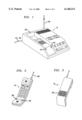
- FIG. 1 shows a perspective view of a cordless telephone base unit and telephone answering device in combination, to which the present invention may be applied;
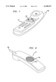
- FIG. 2 shows a front perspective view of a cordless telephone portable unit to which the present invention may be applied
- FIG. 3 shows a rear perspective view of a cordless telephone portable unit to which the present invention may be applied
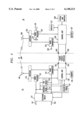
- FIG. 4 is a functional block representation of the cordless telephone base unit and telephone answering device of FIG. 1 in combination, and also the cordless telephone portable unit of FIGS. 2, 3, 7 and 8, operative in accordance with the principles of the present invention;
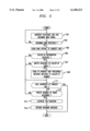
- FIG. 5 shows a flow chart for illustrating the operation of the cordless telephone with the desired functionality in the execution of the telephone answering device functions
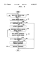
- FIG. 6 shows a flow chart for illustrating the operation of the base unit with the desired functionality in accessing the telephone answering device functions
- FIG. 7 shows a front perspective view of an alternative portable unit to which the present invention may be applied.
- FIG. 8 shows a rear perspective view of an alternative portable unit to which the present invention may be applied.
- FIGS. 1, 2 and 3 there is shown a communication system which includes a base unit 10, shown in FIG. 1, along with a portable transceiver or handset unit 20, shown in both FIGS. 2 and 3, with which the base unit 10 communicates.
- the base unit 10 includes both a telephone answering device (TAD) for automatically responding to incoming telephone calls and a fixed transceiver for communicating voice and TAD signals between the base unit 10 and the handset unit 20.
- TAD telephone answering device
- the base unit 10 transmits to and receives signals from the handset unit 20 over an antenna 106.
- the base unit also receives signals from and couples signals onto a telephone line 101, 102.
- the base unit as more fully described later herein, through TAD circuitry incorporated therein, also answers calls, records messages when a user cannot or does not want to answer the telephone, and notes the time and day of each message.
- the TAD circuitry also is capable of recording memos and telephone conversations and permits a user to retrieve messages when the user is away from home.
- the handset unit transmits and receives signals over an antenna 206 and is used to contact base unit 10 for enabling the placing of a call over the telephone line 101, 102 as well as for accessing features and functions provided by the TAD circuitry located in the base unit.
- a randomly generated security code stored in base unit 10 is transferred to handset unit 20 while the handset unit is located in a mating cradle 105 in the base unit 10.
- a battery which allows operation of the handset unit 20 while remote from the base unit 10, is normally charged when the handset unit 20 is placed in the base unit charging cradle 105. This battery is described later herein with reference to FIG. 4.
- a direct-current charging path for the battery is established over contacts 103 and 104 in the base unit 10 and contacts 203 and 204 in the handset unit 20 for charging of the battery. These contacts also allow transfer circuits in the base unit 10 and the handset unit 20 to respectively transmit and receive the security code and also an operating frequency channel over this path.
- a format suitable for transferring of the security code and other data over a direct-current charging path is described in U.S. Pat. No. 4,736,404 issued to R. E. Anglikowski et al. on Apr. 5, 1988.
- a controlled power-up/power-down mode of operation is implemented. Power to a radio receiver, a control unit and certain other selected circuitry in the handset unit 20 are controlled to minimize power consumption when the handset unit 20 is in a standby-and-out-of-cradle state.
- the handset unit 20 resides in this state while not being used by a user in communicating with the base unit 10. Power to other non-essential circuitry in the handset unit is turned completely off during this power saving state.
- multiple events can cause the control unit to turn on to a full operating mode from the alternating power-up/power-down mode.
- a key depression on the handset unit, detection of a digitally formatted radio signal transmitted from the base unit 10, and the handset unit 20 being cradled in the base unit 10 for charging are all events which cause the control unit in the handset unit 20 to turn on to and remain in the full operating mode until processing of these events is completed.
- a message format for the radio signals transmitted between the base unit and the handset unit is provided in the form of frequency shift keyed (FSK) signals and includes a data field.
- This data field may be in the form of either command opcode data or dial digit data, thereby allowing for many different commands or functions.
- the message format also includes a synchronizing header signal that immediately precedes the data field.
- a format suitable for transmission of the data messages between the base unit 10 and the handset unit 20 is described in U.S. Pat. No. 4,731,814 which issued to W. R. Becker et al. on Mar. 15, 1988.
- any communications between the base unit and the handset unit are established first through interpretation of the data field in the FSK signals.
- the base unit receives the incoming ringing signal on the telephone lines, it transmits the FSK signal with the ring-on opcode to the handset unit for changing the handset unit 20 from the alternating power-up/power-down mode to the full operating mode.
- the security code that the handset unit recognizes also must be in the data field received by the handset unit.
- the handset unit receiver When a signal is transmitted on the frequency on which the handset unit 20 is monitoring, the handset unit receiver turns on and remains on long enough to receive and interpret the security code transmitted by a base unit on this frequency.
- the security code identifies the transmitting base unit as being the correct base unit to which the handset unit should respond. All other signals received on this frequency without a security code that the handset unit recognizes are ignored.
- the handset unit Once the handset unit has verified that the signaling base unit has the proper security code, it turns on to a full operating mode, in this instance the PHONE mode. If the handset unit does not recognize the code being transmitted by the base unit, it leaves the full operating mode and returns to the power-up/power-down mode of operation.
- This common security code is also included in any transmission of the FSK signals from the handset unit to the base unit and must similarly identify the handset unit as being the correct handset unit to which the base unit should respond.
- the handset unit receiver also remains on for approximately 10 seconds whenever a user goes on-hook at the handset unit, i.e., terminates the interaction with or through the base unit while in the PHONE mode, INTERCOM mode or TAD interrogation mode.
- the communication system includes a call screening feature operable from the handset unit 20.
- this feature in a first configuration, allows a user holding the handset unit 20 to monitor at this unit incoming messages received over telephone lines as they are being recorded, without interrupting the recording action of the TAD in the base unit 10 and without directly connecting the user to the calling party.
- This functionality is invoked via a first selection button (not shown) on the handset unit which transmits a first unique digital command information code from the handset unit to the base unit 10.
- This command information code causes the base unit 10 to transmit on the frequency which the handset unit 20 is then monitoring the prerecorded message that is outgoing over the telephone lines and any message that is incoming over the telephone lines.
- a user at the handset unit may end the monitoring of an incoming message either by answering the call or without answering the call.
- the user depresses a second selection button on the handset unit which transmits a second unique digital command information code from the handset unit to the processor in the cordless telephone base unit.
- this information code is received in the base unit 10
- the TAD stops playing the prerecorded outgoing message or recording any incoming message, and both the RF transmitter and the RF receiver in the base unit remain activated for enabling the user at the handset unit to communicate with the calling party.
- the user at the handset unit depresses a third selection button on the handset unit which transmits a third unique digital command information code from the handset unit to deactivate the RF transmitter in the base unit.
- an additional level of convenience in operating the call screening feature from the handset unit 20 is provided for the user of this unit.
- This feature in a second configuration, i.e., auto monitor feature, allows the user at the handset unit to monitor incoming messages received over telephone lines as they are being recorded without the user having to configure the handset unit in any way during actual receipt of the message.
- a built-in loudspeaker 235 shown in FIG. 4, is incorporated into the handset unit 20 for audibly reproducing the incoming message at the handset unit.
- the loudspeaker 235 is optionally preconfigurable to automatically turn on and allow the handset user to conveniently monitor the incoming message without manually manipulating the handset unit in any way during the operation of the TAD circuitry.
- amplifier circuitry driving the loudspeaker is turned off. This operation is explained in greater detail later herein.
- a user at the handset unit may end the monitoring of an incoming message by answering the call.
- the user depresses the second selection button on the handset unit which transmits the second unique digital command information code from the handset unit to the processor in the cordless telephone base unit.
- the TAD circuitry stops playing the prerecorded outgoing message or recording any incoming message, and both the RF transmitter and the RF receiver in the base unit remain activated for enabling the user at the handset unit to communicate with the calling party.
- FIG. 4 there is shown a block representation of the major functional components of the base unit 10 and also of the handset unit 20, the base unit being depicted in FIG. 1, a first handset unit being depicted in both FIGS. 2 and 3, and an alternative handset unit being depicted in both FIGS. 7 and 8, these units all being operative over a plurality of communication channels.
- control unit 120 which advantageously provides a number of control functions.
- the control unit 120 generates security code and frequency channel data, which includes data indicative of an active channel selected by the base unit 10 and initially communicated to the handset unit 20 over the charge contact interface 103, 104, 203, and 204 or subsequently over the radio frequency (RF) link as needed to avoid interference.
- RF radio frequency
- Speakerphone 131 and TAD circuit 132 are advantageously included in the base unit 10 for providing additional functions and features for this unit.
- Circuitry suitable for use in speakerphone 131 is commercially available from AT&T as either speakerphone Model S201 or speakerphone Model 870. This speakerphone circuitry is also suitably described in U.S. Pat. Nos. 4,887,288, 4,901,346 and 4,959,887.
- TAD circuitry has previously been incorporated into cordless telephones. Two such examples are respectively described in U.S. Pat. Nos. 4,677,655 and 4,881,259.
- a cordless answering system Model 5600 commercially available from AT&T incorporates circuitry suitable for use in base unit 10 including, with some modifications which are fully disclosed herein, TAD circuit 132.
- Additional circuitry suitable for use in TAD circuit 132 is commercially available from AT&T in digital answering systems, Models 1343, 1545, 1710, 1756 and 1830, for example.
- a conventional power supply (not shown) provides operating power for all of the circuitry in the base unit 10.
- the communication system includes a call screening feature operable in the first configuration by the user while holding the handset unit 20 or, in accordance with the disclosed embodiment, operable in the second configuration automatically without assistance from the user.
- the control unit 120 interprets the first unique digital command information code received from the handset unit 20 and causes the radio transmitter 122 in the base unit to become activated for transmitting directly to the handset unit a prerecorded message that is outgoing over the telephone lines and any message that is incoming over the telephone lines.
- the user of the handset may monitor an incoming message at the handset unit by depressing the first selection button (not shown) on the handset unit which transmits the first unique digital command information code from the handset unit to the base unit 10.
- a user at the handset unit may end the monitoring of an incoming message either by answering the call or without answering the call.
- the second unique digital command information code is transmitted from the handset unit and received by the control unit 120 in the base unit 10.
- the control unit causes the TAD circuit 132 to stop playing the prerecorded outgoing message or recording any incoming message, and also keeps activated both the RF transmitter and the RF receiver in the base unit for enabling the user at the handset unit to communicate with the calling party.
- the user at the handset unit desires to end the monitoring of incoming messages without answering the call, the user depresses the third selection button on the handset unit which transmits the third unique digital command information code from the handset unit to the base unit.
- This information code causes the control unit 120 to deactivate the RF transmitter in the base unit.
- an additional level of convenience in operating the call screening feature from the handset unit 20 is provided for the user of this unit.
- This call screening feature while in the second configuration, allows the user at the handset unit to monitor incoming messages received over telephone lines as they are being recorded without the user having to configure the handset unit in any way during the receipt of the message.
- the built-in loudspeaker 235 in the handset unit 20 audibly reproduces the incoming message at the handset unit when the TAD circuitry 132 in the base unit 10 answers an incoming call.
- a fourth unique digital information code is transmitted from the base unit to the handset unit when the TAD circuit 132 goes off-hook to answer the incoming call.
- this control unit determines whether a call monitoring flag is set or not set in memory in the handset unit. If the call monitoring flag is set, amplifier circuitry in radio receiver 223 for operating the loudspeaker 235 is automatically turned on by the control unit 220 and allows the handset user to conveniently monitor the incoming message without manually manipulating the handset unit in any way during the operation of the TAD circuit 132. Once receipt of the incoming message is completed, as reflected by transmission of a fifth unique digital information code from the base unit when the TAD circuit 132 goes on-hook, the amplifier circuitry driving the loudspeaker is turned off.
- a user at the handset unit may end the monitoring of an incoming message, while the call screening feature is in the second configuration, by answering the call.
- the second unique digital command information code is transmitted from the handset unit and received by the control unit 120 in the base unit 10.
- the control unit causes the TAD circuit 132 to stop playing the prerecorded outgoing message or recording any incoming message, and keeps activated both the RF transmitter 122 and the RF receiver 123 in the base unit for enabling the user at the handset unit to communicate with the calling party.
- the user of the handset unit also may desire to end monitoring of the incoming message without answering the call, while the call screening feature at the handset unit is operating in the second configuration.
- the user depresses the third selection button on the handset unit which transmits the third unique digital command information code from the handset unit to the base unit.
- This information code causes the control unit 120 to deactivate the RF transmitter 122 in the base unit 10.
- the security code data transmitted from the base unit 10 to the handset unit 20 via the battery charge contact interface, is transmitted while establishing initial communications or call set-up during the time that the handset unit 20 is located remote from the base unit 10 as well as during the transfer of subsequent opcode data between these units during ongoing communications.
- This control unit 120 compares the received security code data with its stored security code data during the establishing of the two-way RF communications link between the handset unit 20 and the base unit 10. A favorable comparison of the data from the two security codes must be achieved in order for the base unit 10 to respond to a request-for-service signal from a handset unit.
- This control unit 120 also receives and processes opcode data provided by the handset unit 20 for dialing and providing signaling information out to a central office or other appropriate switch via a telephone circuit 121 and over tip-ring lines 101 and 102.
- Control unit 120 may be implemented through the use of a microcomputer containing ROM, RAM and through use of the proper coding. Such a microcomputer is known in the art and is readily available from semiconductor manufacturers such as Signetics, Intel and AMD.
- the telephone circuit 121 serves as a "plain old telephone service" (POTS) interface for voice signals on the tip-ring lines 101 and 102 which are sent to radio transmitter 122, speakerphone 131, and TAD circuit 132. And voice signals from the radio receiver 123, speakerphone 131, and TAD circuit 132 are received by the telephone circuit 121.
- POTS plain old telephone service
- Both the base unit 10 and the handset unit 20 are operable on a plurality of communication channels.
- the control unit 120 configures the radio transmitter 122 and the radio receiver 123 in the base unit 10 for proper operation on the active one of the plurality of channels when communicating with handset unit 20.
- the transmit and receive signals of the base unit 10 are coupled to a duplexer 124 which permits the radio transmitter 122 and the radio receiver 123 to both simultaneously operate over antenna 106 while preventing the output of transmitter 122 from being coupled directly to the input of the receiver 123.
- transmitter 122 is turned off while receiver 123 remains on to detect the request-for-service signal.
- a caller-ID circuit 133 along with the control unit 120 performs the caller-ID function such as described in U.S. Pat. No. 5,377,261 as part of an alerting process available to the user of the handset unit.
- a name and the receivable caller-ID telephone number, including the area code are stored into memory.
- Such memory storage is provided in memory 129 which may be either random-access-memory (RAM) or electrical erasable-read-only-memory (EEPROM).
- RAM random-access-memory
- EEPROM electrical erasable-read-only-memory
- the user configures the memory by entering each of "N" desired telephone numbers, typically 10, into the memory table for subsequent access and comparison by the control unit 120 when a caller-ID number is received from a calling party.
- N desired telephone numbers
- the number 10 is suggested as being typical for N, it is understood that N may be either less than or greater than this suggested value.
- a voice help menu advantageously provides coding instructions and guides the user through the correct steps necessary to configure the memory 129 in the base unit 10 with the table of caller-ID numbers.
- the voice help menu is accessed by pressing a designated button and obtaining a 2-beep signal to indicate to the user that the system is ready to accept a command.
- the commands are usually accessed by pressing a number which represents a particular function. For example, the user, after entering the voice help menu, might hear "to play all messages, press 1," or "to play new messages, press 2," or "to program caller-ID numbers, press 9.”
- the user In addition to entering the telephone caller-ID number for people the user expects to call at some point in time, the user also is able to associate a short message with each number so that the message may be later played through the loudspeaker 235 in the handset unit 20 when the identified caller-ID number is detected on the tip-ring lines.
- a message is received from a specific caller-ID number, such as the user's mother, the user can prerecord and the control unit 120 access a message that states, for example, "call from Mom,” so that the user knows who is calling whenever that specific caller-ID number is detected on the tip-ring lines.
- control unit 220 which stores the security code data that is generated by the base unit 10 and provided to the handset unit 20.
- This security code data stored in control unit 220 is transmitted from the handset unit 20 to the base unit 10 while establishing initial communications through a request for service signal as well as during the transfer of subsequent opcode data to the base unit.
- These signals are transmitted in a frequency shift keying (FSK) format and include a synchronizing signal immediately followed by a data field which includes the security code generated by the control unit 120.
- FSK frequency shift keying
- this control unit 220 may be implemented through the use of a microcomputer containing ROM, RAM and through use of the proper coding. Such a microcomputer is known in the art and is readily available from semiconductor manufacturers such as Signetics, Intel and AMD.
- Communications with the base unit 10 are provided via a radio transmitter 222 and a radio receiver 223 in the handset unit 20.
- the output of the transmitter 222 and input for the receiver 223 are commonly coupled through a duplexer 224 to an antenna 206.
- the receiver 223 demodulates voice signals transmitted by the base unit 10 and selectively, under the control of the control unit 220, couples these signals to either the acoustic receiver 231 or the acoustical loudspeaking device such as, for example, loudspeaker 235.
- the transmitter 222 has as its input speech signals from a microphone 230, security code data from control unit 220, and opcode data representative of entries on a keypad 228, all of which it transmits to the base unit 10.
- a keypad 228 in the handset unit 20 is used for entering dial digits and control functions executable by the control unit 220 or transmitted to the base unit 10.
- the keypad 228 is also used for accessing features provided by the TAD circuit 132 in the base unit 10. Such features include call screening allowing for automatically as well as manually monitoring an incoming message, playing messages, saving messages and clearing messages.
- a battery 227 is also included in the handset unit 20 for providing operating power for all circuitry in this unit.
- An optional display 237 in a handset unit provides an alternative way to that provided by the voice help menu for programming telephone numbers of interest into the caller-ID table located in memory 129.
- Such an optional display is illustratively shown in the telephone handset unit 70 of FIG. 7.
- Other features of handset unit 70, however, are similar to those described for handset unit 20.
- the user activates the number entry process by depressing a designated button on the handset unit. This designated button then causes the display to cycle through menu screens provided on the display.
- the number entry process is activated, the user is queried by the display for each of the numbers to be entered into the caller-ID table. In response to this query, the user enters each number into the table, this number being visible in the display 237.
- the user When the user is queried as to whether to have the auto monitor feature (speakerphone at handset is activated and automatically monitors incoming calls) on or off, the user simply responds to a yes or no query prompt on the display and the auto monitor feature flag is either set or not set.
- a controlled power-up/power-down mode of operation for the handset unit 20 is implemented in accordance with the teachings of U.S. Pat. No. 4,731,814 issued to W. R. Becker et al.
- the battery 227 in the handset unit 20 is normally charged while the handset unit is placed in the cradle of the base unit.
- power to the control unit 220, receiver 223 and certain other selected circuitry in the handset unit 20 is controlled to minimize power consumption. Power to other non-essential circuitry in the handset unit 20 is turned completely off during this state.
- the handset unit automatically turns on to a full operating mode from the controlled power-up/power-down mode in response to events such as a user depressing a key on the keypad 228 or the receipt of a ring indication from a base unit, the ring indication being indicative of an incoming call directed to the handset unit.
- FIG. 5 there is shown a flow chart for illustrating the operation of the base unit in the communication system for providing the desired functionality in the execution of the TAD functions.
- the functions in this flow chart are advantageously provided by a process or program stored in ROM contained in control unit 120.
- step 501 the TAD circuitry 132 monitors the telephone line for an incoming ring signal. From step 501, the process advances to decision 503 where it is determined whether an incoming ring signal has been detected. If no ring signal has been detected, the process returns to step 501 where it looks for an incoming ring signal. If an incoming ring signal is detected at step 503, however, the process advances to step 505 where a ring opcode is transmitted from the base unit to the handset unit. If the handset unit is then cradled in the base unit, the ring opcode is transmitted through the battery charge contacts to the handset unit. However, if the handset unit is removed from the base unit, the ring opcode is transmitted to the handset unit over the frequency channel previously selected and communicated by the base unit to the handset unit.
- step 505 the process advances to decision 506 where it is determined whether caller-ID information has been received along with the incoming ring signal. If caller-ID information has been received, the process advances to decision 507 where it is determined if a match is available in memory 129, shown in FIG. 4, which contains the caller-ID table. As earlier indicated herein, this caller-ID table has N number of telephone numbers which the user has previously identified and prerecorded a message to be associated with each incoming caller-ID recognized number.
- step 507 the process advances to step 509 where the base unit sends to the handset unit the prerecorded message matched to the caller-ID number. From decisions 506 and 507, respectively, when no caller-ID information is received or when no match is available in the caller-ID table for the received caller-ID information, the process advances to decision 511. From step 509, the process also advances to decision 511. At decision 511, a determination is made as to whether the call has been answered at the handset unit. If so, the process is exited. If a call has not been answered at this decision, however, the process advances to decision 512 where it is determined whether a preset number of rings selectable by the user has occurred.
- step 513 the TAD function is activated and the base unit goes off-hook, generating an outgoing message in response to the incoming telephone call. From step 513, the process advances to step 514 where any incoming message is recorded by the TAD circuitry in the base unit. From step 514, the process is exited.
- FIG. 6 there is shown a flow chart illustrating the operation of the handset unit 20 with the desired functionality in accessing the TAD functions available in the base unit.
- the process is entered in decision 601 where it is determined whether a ring opcode has been received from the base unit. The process continues to reside at this decision until such ring opcode is received. Once such a ring opcode has been received, the process advances to step 603 where the ringing function is activated in the handset unit. From step 603, and in accordance with the disclosed embodiment, the process advances to decision 605 where it determines if a loudspeaker flag has been set. This loudspeaker flag determines whether circuitry for the loudspeaker 235 should be activated when caller-ID information has been received with an incoming call which has a telephone number that matches a caller-ID number previously entered in the memory table in the base unit.
- the message previously provided by the user of the telephone to himself or herself for identifying the calling person is played at the speakerphone in the handset unit.
- This loudspeaker flag also determines whether the loudspeaker circuitry should be activated when the TAD circuitry in the base unit goes off-hook and answers a telephone call. For this operation, the user is able to hear the outgoing message and any incoming message from the calling party without manually configuring the handset unit in any way during the TAD operation.
- step 608 the loudspeaker circuitry is activated. If the loudspeaker flag has not been set in decision 605, the process is exited.
- step 608 the process advances to decision 610 where it is determined whether a prerecorded caller-ID matched message is being received. If such a message is being received, the process advances to step 612 where this message is played through the loudspeaker 235. If no such message is being received as determined by decision 610, then the process advances to decision 614 where it is determined whether the call has been answered by a user at the handset unit going off-hook. If the call has not been answered, the process is exited at this decision.
- step 615 the user is able to monitor the execution of the TAD functions through the loudspeaker. That is, the user is able to hear the outgoing prerecorded message and listen to any message being left by the calling party through the loudspeaker.
- step 616 the loudspeaker circuitry is deactivated. From step 616, the process is exited.
- FIGS. 7 and 8 in combination, there are respectively shown a front and rear perspective view of an alternative portable unit 70 to which the present invention may be applied.
- This handset unit communicates with the base unit 10 though RF signals on a designated channel.
- An antenna 706 is used in communicating with the base unit.
- This handset unit incorporates a display 237 for the user to use in communicating with the base unit. This display could also show the caller-ID number of the calling party if desired by the user at the handset unit.
- a loudspeaker 735 used for providing the auto monitor feature at the handset unit.
Abstract
Description
Claims (6)
Priority Applications (3)
| Application Number | Priority Date | Filing Date | Title |
|---|---|---|---|
| US08/498,306 US6148213A (en) | 1995-07-05 | 1995-07-05 | Method and apparatus for accessing a telephone answering device from a cordless telephone portable unit |
| CA002179835A CA2179835C (en) | 1995-07-05 | 1996-06-25 | Method and apparatus for accessing a telephone answering device from a cordless telephone portable unit |
| MXPA/A/1996/002552A MXPA96002552A (en) | 1995-07-05 | 1996-07-01 | Method and apparatus for accessing a telephone answering device, from a portable telephone unit inalambr |
Applications Claiming Priority (1)
| Application Number | Priority Date | Filing Date | Title |
|---|---|---|---|
| US08/498,306 US6148213A (en) | 1995-07-05 | 1995-07-05 | Method and apparatus for accessing a telephone answering device from a cordless telephone portable unit |
Publications (1)
| Publication Number | Publication Date |
|---|---|
| US6148213A true US6148213A (en) | 2000-11-14 |
Family
ID=23980494
Family Applications (1)
| Application Number | Title | Priority Date | Filing Date |
|---|---|---|---|
| US08/498,306 Expired - Lifetime US6148213A (en) | 1995-07-05 | 1995-07-05 | Method and apparatus for accessing a telephone answering device from a cordless telephone portable unit |
Country Status (2)
| Country | Link |
|---|---|
| US (1) | US6148213A (en) |
| CA (1) | CA2179835C (en) |
Cited By (33)
| Publication number | Priority date | Publication date | Assignee | Title |
|---|---|---|---|---|
| US20010028685A1 (en) * | 1999-11-19 | 2001-10-11 | Siemen Information And Communication Mobile Llc | Method and system for power-conserving interference avoidance in communication between a mobile unit and a base unit in a wireless telecommunication system |
| US6351637B1 (en) * | 1998-05-23 | 2002-02-26 | Samsung Electronics, Co., Ltd. | Method of transmitting a caller's identification number to a mobile instrument from a home base station |
| US20020052226A1 (en) * | 2000-10-30 | 2002-05-02 | Pioneer Corporation | Portable information terminal device |
| US6385662B1 (en) * | 1997-10-03 | 2002-05-07 | Ericsson Inc. | Method of processing information using a personal communication assistant |
| US20020085524A1 (en) * | 2000-12-28 | 2002-07-04 | Siemens Information And Communication Products, Inc. | Call screening in a cordless digital system |
| US6463129B1 (en) * | 1969-08-09 | 2002-10-08 | Samsung Electronics, Co., Ltd. | Call screening method of a facsimile system having a stationary main unit connected to a telephone network and a cordless portable unit |
| US20020177428A1 (en) * | 2001-03-28 | 2002-11-28 | Menard Raymond J. | Remote notification of monitored condition |
| US20020183008A1 (en) * | 2001-05-29 | 2002-12-05 | Menard Raymond J. | Power door control and sensor module for a wireless system |
| US20030026416A1 (en) * | 2001-08-01 | 2003-02-06 | Fusco Marc E. | Personalized telephone announcement |
| US6546241B2 (en) * | 1999-11-02 | 2003-04-08 | Agere Systems Inc. | Handset access of message in digital cordless telephone |
| US6556665B1 (en) * | 1998-07-14 | 2003-04-29 | Matsushita Electric Industrial Co., Ltd. | Portable telephone set |
| US6611681B2 (en) * | 1997-09-26 | 2003-08-26 | Daniel A. Henderson | Method and apparatus for an improved call interrupt feature in a cordless telephone answering device |
| US20040007185A1 (en) * | 2002-02-06 | 2004-01-15 | Hitachi Kokusai Electric Inc. | Method of manufacturing a semiconductor device and a semiconductor manufacture system |
| US6690771B2 (en) * | 2000-06-22 | 2004-02-10 | Siemens Information & Communication Mobile, Llc | System and method for answering machine call screening in a cordless digital system |
| US20040100374A1 (en) * | 1998-08-29 | 2004-05-27 | Menard Raymond J. | Systems and methods for transmitting signals to a central station |
| US6766004B1 (en) * | 1999-02-15 | 2004-07-20 | Microsoft Corporation | Method and apparatus for coordinating ringing and audio announcements in a phone system |
| US6792263B1 (en) * | 1997-10-03 | 2004-09-14 | Karen Jeanne Kite | Remote operational screener |
| US20040198461A1 (en) * | 2002-09-12 | 2004-10-07 | Coombes Daniel J. | Method and apparatus for answering incoming calls at a mobile communication device |
| US6804508B1 (en) * | 1998-11-30 | 2004-10-12 | Nec Corporation | Portable communication terminal |
| US20040247086A1 (en) * | 2001-02-26 | 2004-12-09 | Royal Thoughts, Llc | Emergency response information distribution |
| US20040264689A1 (en) * | 2003-06-26 | 2004-12-30 | Uniden Corporation | Telephone equipped with speaker |
| US6888926B2 (en) * | 2001-03-16 | 2005-05-03 | Agere Systems Inc. | Extension telephone answering device and system employing same |
| US6912399B2 (en) * | 2001-01-22 | 2005-06-28 | Royal Thoughts, Llc | Cellular telephone with programmable authorized telephone number |
| US20060003814A1 (en) * | 2004-06-30 | 2006-01-05 | Taryn Moody | Intelligent ringtone service |
| US20060003813A1 (en) * | 2004-06-30 | 2006-01-05 | Seligmann Doree D | Intelligent ringtones |
| US20060072712A1 (en) * | 2001-11-20 | 2006-04-06 | Brother Kogyo Kabushiki Kaisha | Telephone system having message recording function |
| US7224962B1 (en) * | 1997-10-03 | 2007-05-29 | Karen Jeanne Kite | Remote operational screener |
| US20080279346A1 (en) * | 2007-05-07 | 2008-11-13 | Canon Kabushiki Kaisha | Communication apparatus and control method thereof |
| US20090023416A1 (en) * | 2007-07-20 | 2009-01-22 | Haber George T | Mobile Radio Receiver Power Management Systems and Methods |
| US20090203362A1 (en) * | 2008-02-12 | 2009-08-13 | Ure Michael J | Cellphone extensions |
| US20090323911A1 (en) * | 2008-04-07 | 2009-12-31 | James Dury | Method And System For Telephone Message Management |
| USRE41131E1 (en) * | 1998-04-02 | 2010-02-16 | Nec Corporation | Portable telephone capable of increasing facility of operation |
| CN101198041B (en) * | 2006-12-05 | 2010-12-08 | 华为技术有限公司 | Vector quantization method and device |
Families Citing this family (1)
| Publication number | Priority date | Publication date | Assignee | Title |
|---|---|---|---|---|
| WO2000052909A1 (en) * | 1999-02-26 | 2000-09-08 | Robert Provino | Telephone |
Citations (11)
| Publication number | Priority date | Publication date | Assignee | Title |
|---|---|---|---|---|
| JPS5974739A (en) * | 1982-10-20 | 1984-04-27 | Sanyo Electric Co Ltd | Telephone device |
| US4677655A (en) * | 1984-06-01 | 1987-06-30 | Hashimoto Corporation | Cordless telephone with automatic telephone answering/recording function |
| US4881259A (en) * | 1989-01-06 | 1989-11-14 | Dynascan Corporation | Answering machine with cordless telephone |
| US4894861A (en) * | 1987-12-10 | 1990-01-16 | Kokusai Denshin Denwa Kabushiki Kaisha | Terminal in communication network for notifying originating party's number |
| US5063588A (en) * | 1988-11-21 | 1991-11-05 | Motorola, Inc. | Communication system providing automatic identification of calling parties |
| US5224151A (en) * | 1992-04-01 | 1993-06-29 | At&T Bell Laboratories | Automatic handset-speakephone switching arrangement for portable communication device |
| US5253287A (en) * | 1990-09-25 | 1993-10-12 | Sharp Kabushiki Kaisha | Method of operating cordless telephone system |
| US5481596A (en) * | 1994-05-26 | 1996-01-02 | At&T Corp. | Auxiliary baseband telephone interface for an answering machine |
| US5526406A (en) * | 1992-01-29 | 1996-06-11 | Luneau; David J. | Calling party announcement apparatus |
| US5581599A (en) * | 1993-12-30 | 1996-12-03 | Northern Telecom Limited | Cordless telephone terminal |
| US5953656A (en) * | 1996-10-31 | 1999-09-14 | Lucent Technologies Inc. | Method and apparatus for remotely accessing a telephone answering device |
-
1995
- 1995-07-05 US US08/498,306 patent/US6148213A/en not_active Expired - Lifetime
-
1996
- 1996-06-25 CA CA002179835A patent/CA2179835C/en not_active Expired - Fee Related
Patent Citations (12)
| Publication number | Priority date | Publication date | Assignee | Title |
|---|---|---|---|---|
| JPS5974739A (en) * | 1982-10-20 | 1984-04-27 | Sanyo Electric Co Ltd | Telephone device |
| US4677655A (en) * | 1984-06-01 | 1987-06-30 | Hashimoto Corporation | Cordless telephone with automatic telephone answering/recording function |
| US4894861A (en) * | 1987-12-10 | 1990-01-16 | Kokusai Denshin Denwa Kabushiki Kaisha | Terminal in communication network for notifying originating party's number |
| US5063588A (en) * | 1988-11-21 | 1991-11-05 | Motorola, Inc. | Communication system providing automatic identification of calling parties |
| US4881259A (en) * | 1989-01-06 | 1989-11-14 | Dynascan Corporation | Answering machine with cordless telephone |
| US4881259B1 (en) * | 1989-01-06 | 1992-02-25 | Dynascan Corp | |
| US5253287A (en) * | 1990-09-25 | 1993-10-12 | Sharp Kabushiki Kaisha | Method of operating cordless telephone system |
| US5526406A (en) * | 1992-01-29 | 1996-06-11 | Luneau; David J. | Calling party announcement apparatus |
| US5224151A (en) * | 1992-04-01 | 1993-06-29 | At&T Bell Laboratories | Automatic handset-speakephone switching arrangement for portable communication device |
| US5581599A (en) * | 1993-12-30 | 1996-12-03 | Northern Telecom Limited | Cordless telephone terminal |
| US5481596A (en) * | 1994-05-26 | 1996-01-02 | At&T Corp. | Auxiliary baseband telephone interface for an answering machine |
| US5953656A (en) * | 1996-10-31 | 1999-09-14 | Lucent Technologies Inc. | Method and apparatus for remotely accessing a telephone answering device |
Non-Patent Citations (2)
| Title |
|---|
| Owner s Manual, AT&T Cordless Answering System 5600, 1990 AT&T, pp. 24 45. * |
| Owner's Manual, AT&T Cordless Answering System 5600, © 1990 AT&T, pp. 24-45. |
Cited By (46)
| Publication number | Priority date | Publication date | Assignee | Title |
|---|---|---|---|---|
| US6463129B1 (en) * | 1969-08-09 | 2002-10-08 | Samsung Electronics, Co., Ltd. | Call screening method of a facsimile system having a stationary main unit connected to a telephone network and a cordless portable unit |
| US6611681B2 (en) * | 1997-09-26 | 2003-08-26 | Daniel A. Henderson | Method and apparatus for an improved call interrupt feature in a cordless telephone answering device |
| US6385662B1 (en) * | 1997-10-03 | 2002-05-07 | Ericsson Inc. | Method of processing information using a personal communication assistant |
| US7224962B1 (en) * | 1997-10-03 | 2007-05-29 | Karen Jeanne Kite | Remote operational screener |
| US6792263B1 (en) * | 1997-10-03 | 2004-09-14 | Karen Jeanne Kite | Remote operational screener |
| USRE41131E1 (en) * | 1998-04-02 | 2010-02-16 | Nec Corporation | Portable telephone capable of increasing facility of operation |
| US6351637B1 (en) * | 1998-05-23 | 2002-02-26 | Samsung Electronics, Co., Ltd. | Method of transmitting a caller's identification number to a mobile instrument from a home base station |
| US6556665B1 (en) * | 1998-07-14 | 2003-04-29 | Matsushita Electric Industrial Co., Ltd. | Portable telephone set |
| US20040100374A1 (en) * | 1998-08-29 | 2004-05-27 | Menard Raymond J. | Systems and methods for transmitting signals to a central station |
| US6804508B1 (en) * | 1998-11-30 | 2004-10-12 | Nec Corporation | Portable communication terminal |
| US6766004B1 (en) * | 1999-02-15 | 2004-07-20 | Microsoft Corporation | Method and apparatus for coordinating ringing and audio announcements in a phone system |
| US6546241B2 (en) * | 1999-11-02 | 2003-04-08 | Agere Systems Inc. | Handset access of message in digital cordless telephone |
| US20010028685A1 (en) * | 1999-11-19 | 2001-10-11 | Siemen Information And Communication Mobile Llc | Method and system for power-conserving interference avoidance in communication between a mobile unit and a base unit in a wireless telecommunication system |
| US6690771B2 (en) * | 2000-06-22 | 2004-02-10 | Siemens Information & Communication Mobile, Llc | System and method for answering machine call screening in a cordless digital system |
| US20020052226A1 (en) * | 2000-10-30 | 2002-05-02 | Pioneer Corporation | Portable information terminal device |
| US20020085524A1 (en) * | 2000-12-28 | 2002-07-04 | Siemens Information And Communication Products, Inc. | Call screening in a cordless digital system |
| US6912399B2 (en) * | 2001-01-22 | 2005-06-28 | Royal Thoughts, Llc | Cellular telephone with programmable authorized telephone number |
| US20040247086A1 (en) * | 2001-02-26 | 2004-12-09 | Royal Thoughts, Llc | Emergency response information distribution |
| US6888926B2 (en) * | 2001-03-16 | 2005-05-03 | Agere Systems Inc. | Extension telephone answering device and system employing same |
| US20020177428A1 (en) * | 2001-03-28 | 2002-11-28 | Menard Raymond J. | Remote notification of monitored condition |
| US20020183008A1 (en) * | 2001-05-29 | 2002-12-05 | Menard Raymond J. | Power door control and sensor module for a wireless system |
| US20030026416A1 (en) * | 2001-08-01 | 2003-02-06 | Fusco Marc E. | Personalized telephone announcement |
| US7224792B2 (en) * | 2001-08-01 | 2007-05-29 | Qwest Communications International, Inc. | Personalized telephone announcement |
| US7570745B2 (en) * | 2001-11-20 | 2009-08-04 | Brother Kogyo Kabushiki Kaisha | Telephone system having message recording function |
| US20060072712A1 (en) * | 2001-11-20 | 2006-04-06 | Brother Kogyo Kabushiki Kaisha | Telephone system having message recording function |
| US20040007185A1 (en) * | 2002-02-06 | 2004-01-15 | Hitachi Kokusai Electric Inc. | Method of manufacturing a semiconductor device and a semiconductor manufacture system |
| US20040198461A1 (en) * | 2002-09-12 | 2004-10-07 | Coombes Daniel J. | Method and apparatus for answering incoming calls at a mobile communication device |
| US20040264689A1 (en) * | 2003-06-26 | 2004-12-30 | Uniden Corporation | Telephone equipped with speaker |
| US20060003813A1 (en) * | 2004-06-30 | 2006-01-05 | Seligmann Doree D | Intelligent ringtones |
| US20090029683A1 (en) * | 2004-06-30 | 2009-01-29 | Avaya Inc. | Intelligent ringtone service |
| US9516622B2 (en) | 2004-06-30 | 2016-12-06 | Avaya Inc. | System and method for message notification based on text modification |
| US8630671B2 (en) | 2004-06-30 | 2014-01-14 | Avaya Inc. | System and method for message notification based on text modification |
| US20060003814A1 (en) * | 2004-06-30 | 2006-01-05 | Taryn Moody | Intelligent ringtone service |
| US7693553B2 (en) * | 2004-06-30 | 2010-04-06 | Avaya Inc. | Intelligent ringtone service |
| US8463330B2 (en) | 2004-06-30 | 2013-06-11 | Avaya Inc. | Intelligent ringtone service |
| CN101198041B (en) * | 2006-12-05 | 2010-12-08 | 华为技术有限公司 | Vector quantization method and device |
| US8948349B2 (en) * | 2007-05-07 | 2015-02-03 | Canon Kabushiki Kaisha | Communication apparatus and control method thereof |
| US20080279346A1 (en) * | 2007-05-07 | 2008-11-13 | Canon Kabushiki Kaisha | Communication apparatus and control method thereof |
| US8442476B2 (en) * | 2007-07-20 | 2013-05-14 | Cresta Technology Corporation | Mobile radio receiver power management systems and methods |
| US20090023416A1 (en) * | 2007-07-20 | 2009-01-22 | Haber George T | Mobile Radio Receiver Power Management Systems and Methods |
| US8160558B2 (en) * | 2008-02-12 | 2012-04-17 | Ure Michael J | Cellphone extensions |
| US20090203362A1 (en) * | 2008-02-12 | 2009-08-13 | Ure Michael J | Cellphone extensions |
| US20090323911A1 (en) * | 2008-04-07 | 2009-12-31 | James Dury | Method And System For Telephone Message Management |
| US20140314217A1 (en) * | 2008-04-07 | 2014-10-23 | Vtech Telecommunications Limited | Method and system for telephone message management |
| US9203957B2 (en) * | 2008-04-07 | 2015-12-01 | Vtech Telecommunications Limited | Method and system for telephone message management |
| US8755497B2 (en) * | 2008-04-07 | 2014-06-17 | Vtech Telecommunications Ltd. | Method and system for telephone message management |
Also Published As
| Publication number | Publication date |
|---|---|
| CA2179835A1 (en) | 1997-01-06 |
| CA2179835C (en) | 2000-05-16 |
| MX9602552A (en) | 1997-09-30 |
Similar Documents
| Publication | Publication Date | Title |
|---|---|---|
| US6148213A (en) | Method and apparatus for accessing a telephone answering device from a cordless telephone portable unit | |
| US5953656A (en) | Method and apparatus for remotely accessing a telephone answering device | |
| US6901266B2 (en) | Method and apparatus for an improved call interrupt feature in a cordless telephone answering device | |
| US6400814B1 (en) | Telephone with ringer silencer screening feature | |
| US6547620B1 (en) | Communication apparatus, memory medium and method | |
| JPH06232962A (en) | Mobile communication terminal equipment | |
| KR0157710B1 (en) | Method of making a phone call between absentee and visitor | |
| JP3667087B2 (en) | Control method of mobile phone terminal | |
| JPH11317810A (en) | Telephone set | |
| JPH08228220A (en) | Digital cordless telephone system | |
| JPH0224294Y2 (en) | ||
| JPH11146060A (en) | Telephone set with troublesome phone call preventing function | |
| MXPA96002552A (en) | Method and apparatus for accessing a telephone answering device, from a portable telephone unit inalambr | |
| JP4058851B2 (en) | Cordless telephone equipment | |
| EP1895753A1 (en) | Door entryphone system | |
| KR20010090057A (en) | A receiving bell of handset generating apparatus in rf home telephone and method thereof | |
| KR200254224Y1 (en) | Apparatus for announcing a cid number by voice message in a cid service telephone | |
| KR200254223Y1 (en) | A receiving bell of handset generating apparatus in rf home telephone | |
| KR970000671B1 (en) | A door phone system | |
| JPH05252243A (en) | Cordless telephone system | |
| JPH0582104B2 (en) | ||
| JPH08223283A (en) | Telephone system | |
| KR19990016019A (en) | How to Send a Voice Message Reservation | |
| KR20030075875A (en) | Method for controlling a alarm of receiving in mobile phone | |
| JPH10210136A (en) | Portable telephone set |
Legal Events
| Date | Code | Title | Description |
|---|---|---|---|
| AS | Assignment |
Owner name: AT&T IPM CORP., FLORIDA Free format text: ASSIGNMENT OF ASSIGNORS INTEREST;ASSIGNOR:BERTOCCI, GUIDO;REEL/FRAME:007566/0244 Effective date: 19950630 |
|
| AS | Assignment |
Owner name: AT&T CORP., NEW YORK Free format text: ASSIGNMENT OF ASSIGNORS INTEREST;ASSIGNOR:SINGER, HOWARD M.;REEL/FRAME:008068/0982 Effective date: 19960312 |
|
| STCF | Information on status: patent grant |
Free format text: PATENTED CASE |
|
| FEPP | Fee payment procedure |
Free format text: PAYOR NUMBER ASSIGNED (ORIGINAL EVENT CODE: ASPN); ENTITY STATUS OF PATENT OWNER: LARGE ENTITY |
|
| AS | Assignment |
Owner name: THE CHASE MANHATTAN BANK, AS COLLATERAL AGENT, TEX Free format text: CONDITIONAL ASSIGNMENT OF AND SECURITY INTEREST IN PATENT RIGHTS;ASSIGNOR:LUCENT TECHNOLOGIES INC. (DE CORPORATION);REEL/FRAME:011722/0048 Effective date: 20010222 |
|
| FEPP | Fee payment procedure |
Free format text: PAYOR NUMBER ASSIGNED (ORIGINAL EVENT CODE: ASPN); ENTITY STATUS OF PATENT OWNER: LARGE ENTITY Free format text: PAYER NUMBER DE-ASSIGNED (ORIGINAL EVENT CODE: RMPN); ENTITY STATUS OF PATENT OWNER: LARGE ENTITY |
|
| FPAY | Fee payment |
Year of fee payment: 4 |
|
| AS | Assignment |
Owner name: LUCENT TECHNOLOGIES INC., NEW JERSEY Free format text: TERMINATION AND RELEASE OF SECURITY INTEREST IN PATENT RIGHTS;ASSIGNOR:JPMORGAN CHASE BANK, N.A. (FORMERLY KNOWN AS THE CHASE MANHATTAN BANK), AS ADMINISTRATIVE AGENT;REEL/FRAME:018590/0287 Effective date: 20061130 |
|
| FPAY | Fee payment |
Year of fee payment: 8 |
|
| FPAY | Fee payment |
Year of fee payment: 12 |
|
| AS | Assignment |
Owner name: CREDIT SUISSE AG, NEW YORK Free format text: SECURITY INTEREST;ASSIGNOR:ALCATEL-LUCENT USA INC.;REEL/FRAME:030510/0627 Effective date: 20130130 |
|
| AS | Assignment |
Owner name: ALCATEL-LUCENT USA INC., NEW JERSEY Free format text: RELEASE BY SECURED PARTY;ASSIGNOR:CREDIT SUISSE AG;REEL/FRAME:033949/0531 Effective date: 20140819 |