US6147795A - Retrofit heater for erbium fiber in an erbium-doped fiber amplifier (EDFA) - Google Patents
Retrofit heater for erbium fiber in an erbium-doped fiber amplifier (EDFA) Download PDFInfo
- Publication number
- US6147795A US6147795A US09/336,998 US33699899A US6147795A US 6147795 A US6147795 A US 6147795A US 33699899 A US33699899 A US 33699899A US 6147795 A US6147795 A US 6147795A
- Authority
- US
- United States
- Prior art keywords
- heater
- fiber
- temperature
- erbium
- tec
- Prior art date
- Legal status (The legal status is an assumption and is not a legal conclusion. Google has not performed a legal analysis and makes no representation as to the accuracy of the status listed.)
- Expired - Lifetime
Links
Images

Classifications
-
- H—ELECTRICITY
- H01—ELECTRIC ELEMENTS
- H01S—DEVICES USING THE PROCESS OF LIGHT AMPLIFICATION BY STIMULATED EMISSION OF RADIATION [LASER] TO AMPLIFY OR GENERATE LIGHT; DEVICES USING STIMULATED EMISSION OF ELECTROMAGNETIC RADIATION IN WAVE RANGES OTHER THAN OPTICAL
- H01S3/00—Lasers, i.e. devices using stimulated emission of electromagnetic radiation in the infrared, visible or ultraviolet wave range
- H01S3/05—Construction or shape of optical resonators; Accommodation of active medium therein; Shape of active medium
- H01S3/06—Construction or shape of active medium
- H01S3/063—Waveguide lasers, i.e. whereby the dimensions of the waveguide are of the order of the light wavelength
- H01S3/067—Fibre lasers
- H01S3/06754—Fibre amplifiers
-
- H—ELECTRICITY
- H01—ELECTRIC ELEMENTS
- H01S—DEVICES USING THE PROCESS OF LIGHT AMPLIFICATION BY STIMULATED EMISSION OF RADIATION [LASER] TO AMPLIFY OR GENERATE LIGHT; DEVICES USING STIMULATED EMISSION OF ELECTROMAGNETIC RADIATION IN WAVE RANGES OTHER THAN OPTICAL
- H01S3/00—Lasers, i.e. devices using stimulated emission of electromagnetic radiation in the infrared, visible or ultraviolet wave range
- H01S3/10—Controlling the intensity, frequency, phase, polarisation or direction of the emitted radiation, e.g. switching, gating, modulating or demodulating
- H01S3/13—Stabilisation of laser output parameters, e.g. frequency or amplitude
- H01S3/1301—Stabilisation of laser output parameters, e.g. frequency or amplitude in optical amplifiers
- H01S3/13017—Stabilisation of laser output parameters, e.g. frequency or amplitude in optical amplifiers by controlling the temperature of the active medium
-
- H—ELECTRICITY
- H01—ELECTRIC ELEMENTS
- H01S—DEVICES USING THE PROCESS OF LIGHT AMPLIFICATION BY STIMULATED EMISSION OF RADIATION [LASER] TO AMPLIFY OR GENERATE LIGHT; DEVICES USING STIMULATED EMISSION OF ELECTROMAGNETIC RADIATION IN WAVE RANGES OTHER THAN OPTICAL
- H01S3/00—Lasers, i.e. devices using stimulated emission of electromagnetic radiation in the infrared, visible or ultraviolet wave range
- H01S3/02—Constructional details
- H01S3/04—Arrangements for thermal management
- H01S3/0405—Conductive cooling, e.g. by heat sinks or thermo-electric elements
-
- H—ELECTRICITY
- H01—ELECTRIC ELEMENTS
- H01S—DEVICES USING THE PROCESS OF LIGHT AMPLIFICATION BY STIMULATED EMISSION OF RADIATION [LASER] TO AMPLIFY OR GENERATE LIGHT; DEVICES USING STIMULATED EMISSION OF ELECTROMAGNETIC RADIATION IN WAVE RANGES OTHER THAN OPTICAL
- H01S3/00—Lasers, i.e. devices using stimulated emission of electromagnetic radiation in the infrared, visible or ultraviolet wave range
- H01S3/02—Constructional details
- H01S3/04—Arrangements for thermal management
- H01S3/042—Arrangements for thermal management for solid state lasers
-
- H—ELECTRICITY
- H01—ELECTRIC ELEMENTS
- H01S—DEVICES USING THE PROCESS OF LIGHT AMPLIFICATION BY STIMULATED EMISSION OF RADIATION [LASER] TO AMPLIFY OR GENERATE LIGHT; DEVICES USING STIMULATED EMISSION OF ELECTROMAGNETIC RADIATION IN WAVE RANGES OTHER THAN OPTICAL
- H01S3/00—Lasers, i.e. devices using stimulated emission of electromagnetic radiation in the infrared, visible or ultraviolet wave range
- H01S3/05—Construction or shape of optical resonators; Accommodation of active medium therein; Shape of active medium
- H01S3/06—Construction or shape of active medium
- H01S3/063—Waveguide lasers, i.e. whereby the dimensions of the waveguide are of the order of the light wavelength
- H01S3/067—Fibre lasers
- H01S3/06704—Housings; Packages
-
- H—ELECTRICITY
- H01—ELECTRIC ELEMENTS
- H01S—DEVICES USING THE PROCESS OF LIGHT AMPLIFICATION BY STIMULATED EMISSION OF RADIATION [LASER] TO AMPLIFY OR GENERATE LIGHT; DEVICES USING STIMULATED EMISSION OF ELECTROMAGNETIC RADIATION IN WAVE RANGES OTHER THAN OPTICAL
- H01S3/00—Lasers, i.e. devices using stimulated emission of electromagnetic radiation in the infrared, visible or ultraviolet wave range
- H01S3/05—Construction or shape of optical resonators; Accommodation of active medium therein; Shape of active medium
- H01S3/06—Construction or shape of active medium
- H01S3/063—Waveguide lasers, i.e. whereby the dimensions of the waveguide are of the order of the light wavelength
- H01S3/067—Fibre lasers
- H01S3/06708—Constructional details of the fibre, e.g. compositions, cross-section, shape or tapering
-
- H—ELECTRICITY
- H01—ELECTRIC ELEMENTS
- H01S—DEVICES USING THE PROCESS OF LIGHT AMPLIFICATION BY STIMULATED EMISSION OF RADIATION [LASER] TO AMPLIFY OR GENERATE LIGHT; DEVICES USING STIMULATED EMISSION OF ELECTROMAGNETIC RADIATION IN WAVE RANGES OTHER THAN OPTICAL
- H01S3/00—Lasers, i.e. devices using stimulated emission of electromagnetic radiation in the infrared, visible or ultraviolet wave range
- H01S3/09—Processes or apparatus for excitation, e.g. pumping
- H01S3/091—Processes or apparatus for excitation, e.g. pumping using optical pumping
- H01S3/094—Processes or apparatus for excitation, e.g. pumping using optical pumping by coherent light
- H01S3/094003—Processes or apparatus for excitation, e.g. pumping using optical pumping by coherent light the pumped medium being a fibre
-
- H—ELECTRICITY
- H01—ELECTRIC ELEMENTS
- H01S—DEVICES USING THE PROCESS OF LIGHT AMPLIFICATION BY STIMULATED EMISSION OF RADIATION [LASER] TO AMPLIFY OR GENERATE LIGHT; DEVICES USING STIMULATED EMISSION OF ELECTROMAGNETIC RADIATION IN WAVE RANGES OTHER THAN OPTICAL
- H01S3/00—Lasers, i.e. devices using stimulated emission of electromagnetic radiation in the infrared, visible or ultraviolet wave range
- H01S3/09—Processes or apparatus for excitation, e.g. pumping
- H01S3/091—Processes or apparatus for excitation, e.g. pumping using optical pumping
- H01S3/094—Processes or apparatus for excitation, e.g. pumping using optical pumping by coherent light
- H01S3/0941—Processes or apparatus for excitation, e.g. pumping using optical pumping by coherent light of a laser diode
- H01S3/09415—Processes or apparatus for excitation, e.g. pumping using optical pumping by coherent light of a laser diode the pumping beam being parallel to the lasing mode of the pumped medium, e.g. end-pumping
-
- H—ELECTRICITY
- H01—ELECTRIC ELEMENTS
- H01S—DEVICES USING THE PROCESS OF LIGHT AMPLIFICATION BY STIMULATED EMISSION OF RADIATION [LASER] TO AMPLIFY OR GENERATE LIGHT; DEVICES USING STIMULATED EMISSION OF ELECTROMAGNETIC RADIATION IN WAVE RANGES OTHER THAN OPTICAL
- H01S5/00—Semiconductor lasers
- H01S5/02—Structural details or components not essential to laser action
- H01S5/024—Arrangements for thermal management
- H01S5/02407—Active cooling, e.g. the laser temperature is controlled by a thermo-electric cooler or water cooling
- H01S5/02415—Active cooling, e.g. the laser temperature is controlled by a thermo-electric cooler or water cooling by using a thermo-electric cooler [TEC], e.g. Peltier element
-
- H—ELECTRICITY
- H01—ELECTRIC ELEMENTS
- H01S—DEVICES USING THE PROCESS OF LIGHT AMPLIFICATION BY STIMULATED EMISSION OF RADIATION [LASER] TO AMPLIFY OR GENERATE LIGHT; DEVICES USING STIMULATED EMISSION OF ELECTROMAGNETIC RADIATION IN WAVE RANGES OTHER THAN OPTICAL
- H01S5/00—Semiconductor lasers
- H01S5/06—Arrangements for controlling the laser output parameters, e.g. by operating on the active medium
- H01S5/068—Stabilisation of laser output parameters
- H01S5/06804—Stabilisation of laser output parameters by monitoring an external parameter, e.g. temperature
Definitions
- the present invention pertains to fiber optic systems utilizing erbium-doped fiber amplifiers (EDFA). More particularly, the invention relates to a heating system for inclusion into an existing EDFA optic system for heating an erbium fiber to maintain optimal EDFA performance.
- EDFA erbium-doped fiber amplifiers
- EDFAs in fiber optic communication systems
- Such EDFAs are used in conjunction with a pump laser which provides optical power at a select frequency for EDFA operation.
- the pump laser and a thermo-electric cooler (TEC) are produced on a common substrate or chip and the TEC is used to regulate the laser temperature by heating and cooling the pump laser.
- a pump laser 12 is thermally connected to a TEC 14 which, depending on certain conditions, provides heat to and removes heat from the pump laser.
- the laser temperature is determined using a temperature sensor such as a thermistor 16 connected to a control circuit 18. It is desirable for pump laser 12 to operate below a maximum temperature value and above a minimum temperature value.
- the control circuit 18 measures the voltage drop across the thermistor 16 and, depending on the measurement, generates a control signal to cause heating or cooling by the TEC.
- a switching means 20 is connected between a positive voltage supply (V+) and a negative voltage supply (V-).
- control circuit 18 When a temperature below the minimum desired temperature is measured, the control circuit activates the switching means 20 to provide a positive current to the TEC for heating the TEC and, consequently, the laser 12. If, on the other hand, a temperature above the maximum desired temperature is measured from thermistor 16, control circuit 18 causes switching means 20 to provide a negative or oppositely-flowing current to the TEC, thereby causing the TEC to cool the laser.
- the temperature sensor 16 is influenced by heat from the EDFA system environment, by heat produced in normal operation by the pump laser 12, and by heat removed (or added) by the TEC 14.
- the control circuit 18 responds to the temperature of the temperature sensor 16 by activating the switching means 20 to provide an electric current to the TEC 14 to cause heat to be removed from the region in which the temperature sensor 16 and pump laser 12 are disposed.
- the control circuit 18 responds to the temperature of the temperature sensor 16 by activating the switching means 20 to provide electric current to the TEC 14 to cause heat to be added to the region in which the temperature sensor 16 and pump laser 12 are disposed.
- a temperature sensor 16 disposed in thermal contact with pump laser 12 and TEC 14 can be used in conjunction with a control circuit 18 to determine whether the environment temperature lies above a certain maximum or below a certain minimum temperature.
- a heating system to control the temperature of the erbium fiber, (e.g. to maintain the fiber temperature within a specified range), thereby controlling the variation in the gain spectrum.
- This can be accomplished by designing a heating system where the erbium fiber and a temperature sensor are both in thermal contact with a heating element.
- a control circuit such as control circuit 18 of FIG. 1 can be used to measure the voltage drop across the temperature sensor and, when the measured voltage exceeds a certain value, the control circuit activates a switch which provides electric current to the heating element for heating the erbium fiber to a temperature above a selected minimum temperature.
- a heating system can be incorporated in the EDFA design.
- this requires the inclusion in the EDFA system of a heating element, a temperature sensor, a control circuit to monitor the temperature sensor and a switch to provide electric current to the heating element.
- no provisions exist for an erbium fiber heating system in EDFA systems designed and built prior to the discovery of the desirability of controlling the erbium fiber temperature. Providing control of the erbium fiber temperature for such existing systems would require extensive redesign of control circuitry, including the addition of a temperature sensor and a supply of electric current for a heating element.
- a heater system for heating an erbium fiber in an erbium-doped fiber amplifier (EDFA) used in a fiber optic communications system to maintain the temperature of the fiber above a minimum temperature value.
- the heater system is disposed in an environment and contains an integrated pump laser for driving the EDFA, and a thermoelectric cooler (TEC) thermally connected to the pump laser for regulating the temperature of the laser so that the laser temperature is maintained below a maximum temperature value.
- TEC thermoelectric cooler
- a thermistor is provided for measuring the temperature of the environment.
- a control circuit is connected to the thermistor for dynamically producing a control signal in response to the measured temperature.
- a heater is disposed in thermal contact with the erbium fiber to heat the fiber in response to the control signal.
- a switching mean electrically connects the heater and TEC to the control circuit for directing current to the heater for heating the fiber when the temperature measured by the thermistor is below the minimum temperature value, and for directing current to the TEC when the temperature measured by the thermistor is above the maximum temperature value.
- the heater and fiber are arranged as a composite element for providing efficient heating to the fiber in the event the measured temperature approaches or falls below a minimum temperature value and the thermistor is disposed in thermal contact with the TEC to provide efficient sensing of the pump laser temperature.
- FIG. 1 is a block diagram of a prior art system for heating and cooling a pump laser in a fiber optic communications system
- FIG. 2 is a block diagram of a heater system in accordance with the present invention.
- FIG. 2A is a block and partial schematic diagram of the heater system of FIG. 2;
- FIG. 3 is a cross-sectional view of an arrangement of heater elements and erbium fibers in accordance with a preferred embodiment of the present invention
- FIG. 4 is a cross-sectional view of an arrangement of heater elements and erbium fibers in accordance with another embodiment of the present invention.
- FIG. 5 is a cross-sectional view of a composite erbium fiber and heater element in accordance with yet another preferred embodiment of the present invention.
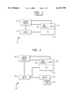
- FIG. 2 depicts a block representation of an erbium-doped fiber amplifier (EDFA) heater system 100 in accordance with the currently preferred embodiment of the present invention.
- the EDFA system is contained in an environment, such as an outdoor environment and is, therefore, exposed to the temperature fluctuations and variations in the environment.
- system 100 includes a pump laser 112 used for providing operating optical power to an erbium fiber 122 in a manner well-known to those having ordinary skill in the art.
- the laser 112 is typically formed on a common substrate with a thermal-electric cooler (TEC) 114 that is used for cooling the laser 112 when the laser temperature exceeds a maximum temperature value.
- the temperature of the laser is sensed by a temperature sensor 116 which is in the form of a thermistor integrally formed on a common substrate with the laser and TEC.
- TEC thermal-electric cooler
- the temperature sensor 116 is preferably integrally formed with the laser, to measure the ambient temperature of the environment in which the system 100 is disposed or contained.
- the temperature sensor 116 like the sensor 16 of FIG. 1, is preferably a thermistor that dynamically responds to and calculates temperature changes as changes in its resistance value.
- a control circuit 118 similar to control circuit 18 of FIG. 1, is provided for determining the temperature value from thermistor 116. As is known in the art, the control circuit performs several functions, such as operating the pump laser 112 at appropriate times, as well as tuning the pump laser to accommodate for wavelength shifts, etc.
- the control circuit 118 also generates a control signal in response to the measured temperature which is used, as explained more fully below, to heat the erbium fiber in the event that the measured temperature is at or below a minimum predetermined temperature value, and to cool the laser 112 in the event that the measured temperature is at or above a maximum predetermined temperature value.
- a heater unit 124 is disposed in thermal contact with an erbium fiber 122.
- the heater is preferably a resistive heater that generates heat when current is applied.
- the generated heat is thermally transferred to the fiber 122 to heat the fiber.
- the thermoelectric cooler (TEC) 114 as explained above, is provided in thermal contact with the laser 112 and integrally formed therewith; the operation of the TEC is well-known to those having ordinary skill in the art.
- the TEC is capable of both heating and cooling the laser 112.
- the TEC when a positive current is directed to the TEC 114, the TEC functions as a heater for heating the laser, but when a negative current, i.e. a current flowing in a direction opposite the direction of flow of the positive current, flows into the TEC, the TEC functions to cool or remove heat from the laser.
- a heater 124 can be incorporated in or retro-fit to the existing system 10, in conjunction with modifications to the switch 20, to provide for both heating of an erbium fiber and cooling of a pump laser.
- a switching means 120 directs current generated by the control circuit 118 to either the TEC 114 or the heater 124 depending on the measured temperature determined by temperature sensor 116.
- the pump laser 112 will operate efficiently at low temperatures but not at high temperatures.
- positive current generated by control circuit 18 can be diverted by the switch 120 from the TEC to the heater 124 and used for heating the fiber.
- control circuit 118 In operation, and in the event that the environment temperature approaches or falls below a minimum temperature value (T min ), the control circuit 118 will sense the temperature from sensor 116 and generate a control signal which is electrically conveyed to the switch means 120. This causes the switch means to provide current to the heater 124 to heat the fiber 122 to a temperature above T min . If, on the other hand, the temperature value approaches or exceeds a maximum temperature value (T max ), the control signal produced by control circuit 118 causes switch means 120 to direct current to the TEC 114 for cooling the laser 112.
- FIG. 2A a schematic block representation of a currently preferred arrangement of the heater system 100 is there shown.
- the heater 124 is connected in parallel across the TEC 114 and the switching means is implemented by a pair of diodes D 1 , D 2 .
- control circuit 118 When a high temperature is measured from temperature sensor 116, e.g. a temperature near or above T max , control circuit 118 will generate a control signal current I 1 .
- Diodes D 1 and D 2 are arranged, as shown, such that current I 1 is permitted to flow through D 1 and cause TEC 114 to cool laser 112, while diode D 2 prevents current I 1 from entering heater 124.
- current I 2 is produced by control circuit 118 and is permitted, by diode D 2 , to flow through heater 24 and heat fiber 122 while diode D 1 prevents current I 2 from flowing through TEC 114.
- diodes are shown in FIG. 2A to implement the switching means 120, the function of the switching means can be produced in numerous ways, as will be apparent to those having ordinary skill in the art, such for example as by employing field-effect transistors (FETs) and/or bipolar-junction transistors (BJTs). This and other such modifications are within the intended scope and contemplation of the invention.
- FETs field-effect transistors
- BJTs bipolar-junction transistors
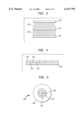
- FIGS. 3-5 depict various thermally-coupled arrangements of an erbium fiber with a heater.
- FIG. 3 shows a cross-section of an erbium fiber having a plurality of fiber elements 222. The fiber elements are arranged in a stacked configuration and are sandwiched between heater elements 224 configured as substantially flat plates.
- FIG. 4 depicts another fiber-heater arrangement wherein individual heater elements 324 are positioned in an interleaved or juxtaposed arrangement with individual fiber elements 322. The resulting combination is mounted to substrate 300 which is preferably constructed of an electrically non-conductive material.
- FIG. 5 shows a cross-section of yet another heater-fiber arrangement; in this figure, a hybrid or composite heater and fiber 400 is formed.
- an erbium fiber element 422 is surrounded or encased by a thermally conductive cladding material 426.
- a heating element 424 is disposed about the cladding for providing heat to the fiber element 422.
- the hybrid element 400 is then encased with a protective coating 428, preferably formed of a polymer material.
Landscapes
- Physics & Mathematics (AREA)
- Electromagnetism (AREA)
- Engineering & Computer Science (AREA)
- Plasma & Fusion (AREA)
- Optics & Photonics (AREA)
- Lasers (AREA)
Abstract
Description
Claims (13)
Priority Applications (1)
| Application Number | Priority Date | Filing Date | Title |
|---|---|---|---|
| US09/336,998 US6147795A (en) | 1999-06-21 | 1999-06-21 | Retrofit heater for erbium fiber in an erbium-doped fiber amplifier (EDFA) |
Applications Claiming Priority (1)
| Application Number | Priority Date | Filing Date | Title |
|---|---|---|---|
| US09/336,998 US6147795A (en) | 1999-06-21 | 1999-06-21 | Retrofit heater for erbium fiber in an erbium-doped fiber amplifier (EDFA) |
Publications (1)
| Publication Number | Publication Date |
|---|---|
| US6147795A true US6147795A (en) | 2000-11-14 |
Family
ID=23318661
Family Applications (1)
| Application Number | Title | Priority Date | Filing Date |
|---|---|---|---|
| US09/336,998 Expired - Lifetime US6147795A (en) | 1999-06-21 | 1999-06-21 | Retrofit heater for erbium fiber in an erbium-doped fiber amplifier (EDFA) |
Country Status (1)
| Country | Link |
|---|---|
| US (1) | US6147795A (en) |
Cited By (23)
| Publication number | Priority date | Publication date | Assignee | Title |
|---|---|---|---|---|
| EP1246322A2 (en) * | 2001-03-29 | 2002-10-02 | Nortel Networks Limited | Method and apparatus for minimising gain deviation in optical fibre amplifier |
| US20020176452A1 (en) * | 2001-03-16 | 2002-11-28 | Lin Hong Tony | Digital control of actively mode-locked lasers |
| WO2003025641A1 (en) * | 2001-09-20 | 2003-03-27 | Corning Incorporated | Apparatus and method for thermally tuning an optical amplifier |
| US6567438B2 (en) * | 2000-07-17 | 2003-05-20 | Calmar Optcom, Inc. | Active and low-power laser stabilization |
| US20030210844A1 (en) * | 2002-03-05 | 2003-11-13 | Motoki Kakui | Optical amplification module, optical amplifier, optical communication system, and white light source |
| US6765938B2 (en) * | 2001-04-23 | 2004-07-20 | The Furukawa Electric Co., Ltd. | System for controlling wavelength of laser beam |
| US6788870B1 (en) | 2001-11-08 | 2004-09-07 | Tyco Telecommunications (Us) Inc. | Isothermal fiber optic tray |
| US6845108B1 (en) | 2001-05-14 | 2005-01-18 | Calmar Optcom, Inc. | Tuning of laser wavelength in actively mode-locked lasers |
| US20050018952A1 (en) * | 2003-06-24 | 2005-01-27 | Kabushiki Kaisha Toshiba | Optical transmitter |
| US20050030540A1 (en) * | 2003-04-11 | 2005-02-10 | Thornton Robert L. | Optical spectroscopy apparatus and method for measurement of analyte concentrations or other such species in a specimen employing a semiconductor laser-pumped, small-cavity fiber laser |
| US20050175272A1 (en) * | 2004-02-10 | 2005-08-11 | Mccaig Peter W. | Optical amplifiers |
| US20050249474A1 (en) * | 2004-05-05 | 2005-11-10 | Tan Chee S | Optical module for housing an optical component |
| US20070195838A1 (en) * | 2006-02-22 | 2007-08-23 | Optical Communication Products, Inc. | Wide temperature range uncooled transcever module for uncontrolled environments |
| JP2007294931A (en) * | 2006-03-31 | 2007-11-08 | Sumitomo Electric Ind Ltd | Optical fiber amplifying module |
| US20080086038A1 (en) * | 2003-04-11 | 2008-04-10 | Thornton Robert L | Method for measurement of analyte concentrations and a semiconductor laser-pumped, small-cavity fiber lasers for such measurements and other applications |
| US20080130101A1 (en) * | 2006-03-31 | 2008-06-05 | Motoki Kakui | Optical fiber amplifying module |
| US20160087401A1 (en) * | 2014-09-22 | 2016-03-24 | Seagate Technology Llc | Heat assisted media recording device with reduced likelihood of laser mode hopping |
| CN106329298A (en) * | 2016-10-25 | 2017-01-11 | 无锡市德科立光电子技术有限公司 | Array optical fiber amplifier |
| US9755394B1 (en) | 2016-04-22 | 2017-09-05 | Adva Optical Networking Se | Fiber temperature control assembly |
| US9940965B2 (en) | 2014-09-22 | 2018-04-10 | Seagate Technology Llc | Thermal management of laser diode mode hopping for heat assisted media recording |
| CN112186491A (en) * | 2020-09-23 | 2021-01-05 | 武汉光迅科技股份有限公司 | Power consumption adjusting method |
| US10901161B2 (en) | 2018-09-14 | 2021-01-26 | Toyota Motor Engineering & Manufacturing North America, Inc. | Optical power transfer devices with an embedded active cooling chip |
| CN112578510A (en) * | 2020-12-01 | 2021-03-30 | 四川华拓光通信股份有限公司 | Circuit compatible with TEC and Heater in optical module and application method |
Citations (3)
| Publication number | Priority date | Publication date | Assignee | Title |
|---|---|---|---|---|
| US5541766A (en) * | 1994-11-30 | 1996-07-30 | At&T Corp. | Gain control for optically amplified systems |
| US5859945A (en) * | 1996-04-01 | 1999-01-12 | Sumitomo Electric Industries, Ltd. | Array type light emitting element module and manufacturing method therefor |
| US5943152A (en) * | 1996-02-23 | 1999-08-24 | Ciena Corporation | Laser wavelength control device |
-
1999
- 1999-06-21 US US09/336,998 patent/US6147795A/en not_active Expired - Lifetime
Patent Citations (3)
| Publication number | Priority date | Publication date | Assignee | Title |
|---|---|---|---|---|
| US5541766A (en) * | 1994-11-30 | 1996-07-30 | At&T Corp. | Gain control for optically amplified systems |
| US5943152A (en) * | 1996-02-23 | 1999-08-24 | Ciena Corporation | Laser wavelength control device |
| US5859945A (en) * | 1996-04-01 | 1999-01-12 | Sumitomo Electric Industries, Ltd. | Array type light emitting element module and manufacturing method therefor |
Non-Patent Citations (7)
| Title |
|---|
| AT&T, Preliminary Data Sheet for 1718 Type EDFA Gain Block, 3 pages, Feb. 1996. * |
| AT&T, Preliminary Data Sheet for 1718-Type EDFA Gain Block, 3 pages, Feb. 1996. |
| Lee et al, OFC 98, vol. 21 pp. 133 134, 1988 OSA Tech. Digest; Abstract Provided Herewith with atill, Feb. 27, 1998. * |
| Lee et al, OFC '98, vol. 21 pp. 133-134, 1988 OSA Tech. Digest; Abstract Provided Herewith with atill, Feb. 27, 1998. |
| Proc. 1992 IEICE Fall Conf., Part 4, pp. 282, Sep. 30, 1992. * |
| Shah et al, 1992 Proc. 42nd Electr. Comp. etech., pp. 842 847; Abstract only herewith, May 20, 1992. * |
| Shah et al, 1992 Proc. 42nd Electr. Comp. etech., pp. 842-847; Abstract only herewith, May 20, 1992. |
Cited By (43)
| Publication number | Priority date | Publication date | Assignee | Title |
|---|---|---|---|---|
| US6567438B2 (en) * | 2000-07-17 | 2003-05-20 | Calmar Optcom, Inc. | Active and low-power laser stabilization |
| US20020176452A1 (en) * | 2001-03-16 | 2002-11-28 | Lin Hong Tony | Digital control of actively mode-locked lasers |
| US6839363B2 (en) | 2001-03-16 | 2005-01-04 | Calmar Optcom, Inc. | Digital control of actively mode-locked lasers |
| EP1246322A2 (en) * | 2001-03-29 | 2002-10-02 | Nortel Networks Limited | Method and apparatus for minimising gain deviation in optical fibre amplifier |
| EP1246322A3 (en) * | 2001-03-29 | 2005-01-26 | Bookham Technology PLC | Method and apparatus for minimising gain deviation in optical fibre amplifier |
| US6765938B2 (en) * | 2001-04-23 | 2004-07-20 | The Furukawa Electric Co., Ltd. | System for controlling wavelength of laser beam |
| US6845108B1 (en) | 2001-05-14 | 2005-01-18 | Calmar Optcom, Inc. | Tuning of laser wavelength in actively mode-locked lasers |
| US6694080B2 (en) * | 2001-09-20 | 2004-02-17 | Corning Incorporated | Apparatus and method for thermally tuning an optical amplifier |
| WO2003025641A1 (en) * | 2001-09-20 | 2003-03-27 | Corning Incorporated | Apparatus and method for thermally tuning an optical amplifier |
| US6788870B1 (en) | 2001-11-08 | 2004-09-07 | Tyco Telecommunications (Us) Inc. | Isothermal fiber optic tray |
| US20030210844A1 (en) * | 2002-03-05 | 2003-11-13 | Motoki Kakui | Optical amplification module, optical amplifier, optical communication system, and white light source |
| US7773295B2 (en) | 2002-03-05 | 2010-08-10 | Sumitomo Electric Industries, Ltd. | Optical amplication module, optical amplifier, optical communication system, and white light source |
| US20090185261A1 (en) * | 2002-03-05 | 2009-07-23 | Sumitomo Electric Industries, Ltd. | Optical amplification module, optical amplifier, optical communication system, and white light source |
| US7525725B2 (en) * | 2002-03-05 | 2009-04-28 | Sumitomo Electric Industries, Ltd. | Optical amplification module, optical amplifier, optical communication system, and white light source |
| US20080086038A1 (en) * | 2003-04-11 | 2008-04-10 | Thornton Robert L | Method for measurement of analyte concentrations and a semiconductor laser-pumped, small-cavity fiber lasers for such measurements and other applications |
| US7633621B2 (en) | 2003-04-11 | 2009-12-15 | Thornton Robert L | Method for measurement of analyte concentrations and semiconductor laser-pumped, small-cavity fiber lasers for such measurements and other applications |
| US7283242B2 (en) | 2003-04-11 | 2007-10-16 | Thornton Robert L | Optical spectroscopy apparatus and method for measurement of analyte concentrations or other such species in a specimen employing a semiconductor laser-pumped, small-cavity fiber laser |
| US20050030540A1 (en) * | 2003-04-11 | 2005-02-10 | Thornton Robert L. | Optical spectroscopy apparatus and method for measurement of analyte concentrations or other such species in a specimen employing a semiconductor laser-pumped, small-cavity fiber laser |
| US20050018952A1 (en) * | 2003-06-24 | 2005-01-27 | Kabushiki Kaisha Toshiba | Optical transmitter |
| US7308182B2 (en) * | 2004-02-10 | 2007-12-11 | Bookham Technology Plc | Optical amplifiers |
| US20050175272A1 (en) * | 2004-02-10 | 2005-08-11 | Mccaig Peter W. | Optical amplifiers |
| US7331722B2 (en) * | 2004-05-05 | 2008-02-19 | Avago Technologies Fiber Ip Pte Ltd | Optical module for housing an optical component |
| US20050249474A1 (en) * | 2004-05-05 | 2005-11-10 | Tan Chee S | Optical module for housing an optical component |
| US20070195838A1 (en) * | 2006-02-22 | 2007-08-23 | Optical Communication Products, Inc. | Wide temperature range uncooled transcever module for uncontrolled environments |
| US7570679B2 (en) | 2006-02-22 | 2009-08-04 | Optical Communication Products, Inc. | Wide temperature range uncooled transceiver module for uncontrolled environments |
| US8493653B2 (en) * | 2006-03-31 | 2013-07-23 | Megaopto Co., Ltd. | Multi-stage optical fiber amplifier with high gain and low duty cycle |
| US20080130101A1 (en) * | 2006-03-31 | 2008-06-05 | Motoki Kakui | Optical fiber amplifying module |
| US8098424B2 (en) * | 2006-03-31 | 2012-01-17 | Sumitomo Electric Industries, Ltd. | Optical fiber amplifying module |
| US20120062985A1 (en) * | 2006-03-31 | 2012-03-15 | Sumitomo Electric Industries, Ltd | Optical fiber amplifying module |
| JP2007294931A (en) * | 2006-03-31 | 2007-11-08 | Sumitomo Electric Ind Ltd | Optical fiber amplifying module |
| US9940965B2 (en) | 2014-09-22 | 2018-04-10 | Seagate Technology Llc | Thermal management of laser diode mode hopping for heat assisted media recording |
| US9905996B2 (en) * | 2014-09-22 | 2018-02-27 | Seagate Technology Llc | Heat assisted media recording device with reduced likelihood of laser mode hopping |
| US20160087401A1 (en) * | 2014-09-22 | 2016-03-24 | Seagate Technology Llc | Heat assisted media recording device with reduced likelihood of laser mode hopping |
| US10325622B2 (en) | 2014-09-22 | 2019-06-18 | Seagate Technology Llc | Thermal management of laser diode mode hopping for heat assisted media recording |
| US10540998B2 (en) | 2014-09-22 | 2020-01-21 | Seagate Technology Llc | Thermal management of laser diode mode hopping for heat assisted media recording |
| US10902876B2 (en) | 2014-09-22 | 2021-01-26 | Seagate Technology Llc | Thermal management of laser diode mode hopping for heat assisted media recording |
| US11450346B2 (en) | 2014-09-22 | 2022-09-20 | Seagate Technology Llc | Thermal management of laser diode mode hopping for heat assisted media recording |
| US11961543B2 (en) | 2014-09-22 | 2024-04-16 | Seagate Technology Llc | Thermal management of laser diode mode hopping for heat assisted media recording |
| US9755394B1 (en) | 2016-04-22 | 2017-09-05 | Adva Optical Networking Se | Fiber temperature control assembly |
| CN106329298A (en) * | 2016-10-25 | 2017-01-11 | 无锡市德科立光电子技术有限公司 | Array optical fiber amplifier |
| US10901161B2 (en) | 2018-09-14 | 2021-01-26 | Toyota Motor Engineering & Manufacturing North America, Inc. | Optical power transfer devices with an embedded active cooling chip |
| CN112186491A (en) * | 2020-09-23 | 2021-01-05 | 武汉光迅科技股份有限公司 | Power consumption adjusting method |
| CN112578510A (en) * | 2020-12-01 | 2021-03-30 | 四川华拓光通信股份有限公司 | Circuit compatible with TEC and Heater in optical module and application method |
Similar Documents
| Publication | Publication Date | Title |
|---|---|---|
| US6147795A (en) | Retrofit heater for erbium fiber in an erbium-doped fiber amplifier (EDFA) | |
| US6567600B2 (en) | Optical amplifying medium component and optical fiber amplifier having the same | |
| US5197076A (en) | Temperature stabilizable laser apparatus | |
| US7835069B2 (en) | WDM optical amplifier with heat radiation from laser source to amplification medium | |
| JPH0411794A (en) | Fiber type optical amplifier | |
| KR20070072401A (en) | Optical assembly comprising multiple semiconductor optical devices and an active cooling device | |
| WO2016029812A1 (en) | Optical fiber grating demodulator and temperature control method thereof | |
| WO2005057246A2 (en) | Temperature-controlled flexible optical circuit for use in an erbium-doped fiber amplifier and method for fabricating the flexible optical circuit | |
| US6522459B1 (en) | Temperature control and monitoring of optical detector components in an optical communication system | |
| KR101122858B1 (en) | Temperature tuning the wavelength of a semiconductor laser using a variable thermal impedance | |
| US6621623B1 (en) | Optical fiber amplifying device stabilized for temperature and signal level | |
| CN201097244Y (en) | Temperature control device for tuning laser | |
| JPWO2003083537A1 (en) | Temperature controller and arrayed waveguide grating type optical wavelength multiplexer / demultiplexer | |
| US20060083273A1 (en) | Temperature tuning the wavelength of a semiconductor laser using a variable thermal impedance | |
| US7056035B2 (en) | Optical module, optical apparatus including optical module, and method for using optical module | |
| EP0816884B1 (en) | Temperature controlled optical coupling structure | |
| US5818097A (en) | Temperature controlling cryogenic package system | |
| JP2004207666A (en) | Laser-diode module, laser-diode apparatus, and optical transmitter | |
| WO1996021129A9 (en) | Temperature controlling cryogenic package system | |
| JP2917606B2 (en) | Laser diode module | |
| US7081712B2 (en) | Thermal cooler for a laser diode package | |
| EP1096626A2 (en) | Process and device for the thermal conditioning of electronic components | |
| JP2001244545A (en) | Semiconductor laser module | |
| KR20000057385A (en) | Package for temperature-sensitive planar optical components | |
| JPH11195827A (en) | Optical fiber type light amplifier |
Legal Events
| Date | Code | Title | Description |
|---|---|---|---|
| AS | Assignment |
Owner name: LUCENT TECHNOLOGIES INC., NEW JERSEY Free format text: ASSIGNMENT OF ASSIGNORS INTEREST;ASSIGNORS:DERBYSHIRE, WILLIAM E.;JAMESON, RALPH STEPHEN;NGUYEN, KHANH CONG;REEL/FRAME:010287/0838 Effective date: 19990824 |
|
| STCF | Information on status: patent grant |
Free format text: PATENTED CASE |
|
| FEPP | Fee payment procedure |
Free format text: PAYOR NUMBER ASSIGNED (ORIGINAL EVENT CODE: ASPN); ENTITY STATUS OF PATENT OWNER: LARGE ENTITY |
|
| FEPP | Fee payment procedure |
Free format text: PAYER NUMBER DE-ASSIGNED (ORIGINAL EVENT CODE: RMPN); ENTITY STATUS OF PATENT OWNER: LARGE ENTITY Free format text: PAYOR NUMBER ASSIGNED (ORIGINAL EVENT CODE: ASPN); ENTITY STATUS OF PATENT OWNER: LARGE ENTITY |
|
| FPAY | Fee payment |
Year of fee payment: 4 |
|
| SULP | Surcharge for late payment | ||
| FPAY | Fee payment |
Year of fee payment: 8 |
|
| AS | Assignment |
Owner name: AGERE SYSTEMS GUARDIAN CORP., PENNSYLVANIA Free format text: MERGER;ASSIGNOR:AGERE SYSTEMS OPTOELECTRONICS GUARDIAN CORP.;REEL/FRAME:027384/0110 Effective date: 20010823 Owner name: AGERE SYSTEMS OPTOELECTRONICS GUARDIAN CORP., PENN Free format text: ASSIGNMENT OF ASSIGNORS INTEREST;ASSIGNOR:LUCENT TECHNOLOGIES INC.;REEL/FRAME:027380/0398 Effective date: 20010130 Owner name: AGERE SYSTEMS INC., PENNSYLVANIA Free format text: MERGER;ASSIGNOR:AGERE SYSTEMS GUARDIAN CORP.;REEL/FRAME:027379/0933 Effective date: 20020829 |
|
| FPAY | Fee payment |
Year of fee payment: 12 |