US6147430A - Stator of AC generator for vehicle - Google Patents
Stator of AC generator for vehicle Download PDFInfo
- Publication number
- US6147430A US6147430A US09/314,886 US31488699A US6147430A US 6147430 A US6147430 A US 6147430A US 31488699 A US31488699 A US 31488699A US 6147430 A US6147430 A US 6147430A
- Authority
- US
- United States
- Prior art keywords
- slots
- stator core
- stator
- insulators
- conductor segments
- Prior art date
- Legal status (The legal status is an assumption and is not a legal conclusion. Google has not performed a legal analysis and makes no representation as to the accuracy of the status listed.)
- Expired - Lifetime
Links
Images
Classifications
-
- H—ELECTRICITY
- H02—GENERATION; CONVERSION OR DISTRIBUTION OF ELECTRIC POWER
- H02K—DYNAMO-ELECTRIC MACHINES
- H02K1/00—Details of the magnetic circuit
- H02K1/06—Details of the magnetic circuit characterised by the shape, form or construction
- H02K1/12—Stationary parts of the magnetic circuit
- H02K1/16—Stator cores with slots for windings
- H02K1/165—Shape, form or location of the slots
-
- H—ELECTRICITY
- H02—GENERATION; CONVERSION OR DISTRIBUTION OF ELECTRIC POWER
- H02K—DYNAMO-ELECTRIC MACHINES
- H02K15/00—Methods or apparatus specially adapted for manufacturing, assembling, maintaining or repairing of dynamo-electric machines
- H02K15/02—Methods or apparatus specially adapted for manufacturing, assembling, maintaining or repairing of dynamo-electric machines of stator or rotor bodies
- H02K15/024—Methods or apparatus specially adapted for manufacturing, assembling, maintaining or repairing of dynamo-electric machines of stator or rotor bodies with slots
-
- H—ELECTRICITY
- H02—GENERATION; CONVERSION OR DISTRIBUTION OF ELECTRIC POWER
- H02K—DYNAMO-ELECTRIC MACHINES
- H02K3/00—Details of windings
- H02K3/32—Windings characterised by the shape, form or construction of the insulation
- H02K3/34—Windings characterised by the shape, form or construction of the insulation between conductors or between conductor and core, e.g. slot insulation
- H02K3/345—Windings characterised by the shape, form or construction of the insulation between conductors or between conductor and core, e.g. slot insulation between conductor and core, e.g. slot insulation
-
- H—ELECTRICITY
- H02—GENERATION; CONVERSION OR DISTRIBUTION OF ELECTRIC POWER
- H02K—DYNAMO-ELECTRIC MACHINES
- H02K3/00—Details of windings
- H02K3/46—Fastening of windings on the stator or rotor structure
- H02K3/48—Fastening of windings on the stator or rotor structure in slots
Definitions
- the present invention relates to an ac generator for a passenger car, a track, or other vehicles that is driven by an internal combustion engine.
- a stator winding of an ac generator for a vehicle is formed of a plurality of conductor segments which are welded together.
- WO92/06527 discloses an example of such a stator winding, in which each of the conductor segments is inserted from one end of the stator core, the ends of conductor segments are welded to one another at the other end of the stator core.
- insulators are inserted into slots of the stator core.
- JP-A-4-17539 discloses insulators, each of which has a U-shape cross section and folded lips formed at opposite ends thereof. The folded lips position the insulator in the slots easily.
- an object of the invention is to provide an improved stator of an ac generator for a vehicle in which insulators can be installed and positioned easily without damage.
- each of a plurality of insulators disposed in slots has a smooth end portion extending from one axial end of the stator core and a stopper engaging the other axial end of the stator core.
- stator winding may be composed of a plurality of conductor segments having a U-turn portion disposed at one end of the stator core, and the stopper portion is disposed at the same end as the U-turn portion.
- FIG. 1 is a cross-sectional view illustrating an ac generator for a vehicle according to a first embodiment of the invention
- FIG. 2 is a perspective view of a U-shaped conductor segment forming a part of a stator winding of the stator according to the first embodiment
- FIG. 3 is a fragmentary cross-sectional view of the stator according to the first embodiment
- FIG. 4 is a perspective view illustrating an insulator to be inserted into one of slots of a stator core of the stator according to the first embodiment
- FIG. 5A is a fragmentary side view of a portion of the stator core and an insulator
- FIG. 5B is a fragmentary side view of a portion of the stator with conductor segments disposed in one of the slots;
- FIG. 6 is a fragmentary side view of a portion of the stator according to the first embodiment of the invention.
- FIG. 7 is a perspective view illustrating coil ends disposed at opposite ends of the stator according to the first embodiment
- FIG. 8 is a fragmentary cross-sectional view of a portion of the stator according to a second embodiment of the invention.
- FIG. 9 is a fragmentary perspective view of the stator according to the second embodiment.
- FIG. 10 is a perspective view illustrating a modified conductor segment
- FIG. 11 is a fragmentary view of the stator having a plurality of the modified conductor segments shown in FIG. 10;
- FIG. 12 is a perspective view illustrating a variation of the insulator to be inserted into one of slots of a stator core of the stator according to the first embodiment.
- FIG. 13 is a perspective view illustrating a variation of an insulator to be inserted into one of slots of a stator core of the stator according to the first embodiment.
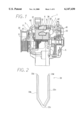
- ac generator 1 As shown in FIG. 1, ac generator 1 according to a first embodiment of the invention includes stator 2, rotor 3, frame 4, rectifier 5, etc.
- Stator 2 is composed of stator core 32, a plurality of conductor segments 33 and a plurality of insulators 34.
- Stator core 32 is a lamination of steel plates having a number of slots formed inside thereof. The portion of conductor segments projecting from stator core 32 form coil ends 31.
- Rotor 3 has field coil 8, a pair of pole cores 7, and shaft 6. Each of the pair of pole cores 7 has six claw pole pieces extending axially to enclose field coil 8.
- Field coil 8 is composed of a cylindrically-wound insulation-coated copper wire.
- Axial flow type cooling fan 11 is welded to the front side pole core 7 to supply cooling air from the front side thereof in both the radial and axial directions.
- Centrifugal cooling fan 12 is welded to the rear side pole core 7 to supply cooling air from the rear side thereof radially outward.
- Frame 4 accommodates stator 2 and rotor 3 and supports rotor 3 to rotate with shaft 6.
- Stator 2 is fixed to frame 4 around the pair of pole cores 7 at a certain gap therefrom.
- Frame 4 has air discharge vents 42 at portions opposite coil ends 31 of stator 2 and air intake vents 41 at the axial ends thereof.
- AC generator 1 described above is rotated in a certain direction by an engine (not shown) via a belt and a pulley 20.
- field coil 8 When field coil 8 is energized by an outside power source, pole cores 7 are excited so that the stator winding provides a three-phase ac voltage. Accordingly, rectifier 5 provides a certain amount of dc current at the output terminals.
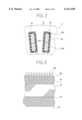
- conductor segment 33 is a U-shaped member made of copper bar or plate.
- Conductor segment 33 has inner conductor portion 33a, outer conductor portion 33b and U-turn portion 33c.
- Each of inner conductor portion 33a and outer conductor portion 33b has straight inner portion disposed in slot 35 and outer portion disposed outside slot 35.
- a pair of conductor segments 33 is disposed in each one of slots 35 and connected to one another in a well known manner to form the stator winding. As illustrated in FIG. 3, inner and outer conductor portions 33a, 33b of conductor segment 33 a rectangular cross-section. The circumferential sides of conductor segment 33 are longer than its radial sides. Conductor segments 33 are coated with insulation film 33i to insulates one segment from another. Insulators 34 insulate conductor segments 33 from the stator core 32.
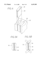
- Column-shaped insulator 34 is made of a resinous sheet, which is rolled to fit the slot as shown in FIG. 4.
- Insulator 34 has a smooth edge at one end and outwardly folded lip 36 at the other end thereof.
- Insulator 34 is inserted into slot 35 in the axial direction with the smooth edge being at the head.
- Folded lip 36 functions as a stopper or positioner of insulator 34.
- Insulator 34 is inserted into slot 35 until folded lip 36 engages an end of stator core 32 so that both ends of insulator 34 can project from stator core 32 as shown in FIG. 5A.
- conductor segments 33 are inserted therein as shown in FIG. 5B and welded to form stator winding.
- conductor segments 33 are insulated from edge portions of stator core 32 by the projected portions of insulator 34.
- folded lip 36 of insulator 34 is disposed at the side of stator core 32 where U-turn portion 33c is located.
- conductor segments 33 are inserted in the same direction as insulators 34 are inserted.
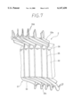
- U-turn portions 33c are disposed at one axial end of stator core 32 and opposite ends 33d are disposed at the other end thereof.
- Each of conductor segments 33 has slant portion 33e forming coil end 31 at one end of stator core 2.
- Slant portions 33e of conductor segments 33 disposed in the outer layers extend in the same direction, while slant portions 33e disposed in the inner layers extend in the different direction.
- Ends 33d of conductor segments 33 are welded by ultrasonic wave welder or arc welder, or are soldered or mechanically connected.
- Conductor segments 33 are made of copper plates, each of which is bent by a press machine to form a U-shape. A number of U-shaped conductor segments 33 are lined up so that U-turn portions 33c can be disposed at the same end of stator core 32. Conductor segments 33 are press-fitted into respective slots 35 so that outer and inner conductor portions 33b, 33a can fit the parallel walls of slot 35 via insulators 34 on the opposite surfaces thereof. As shown in FIG. 3, outer conductor portions 33b are inserted into the inner side of slots 35 that are insulated by insulators 34, and inner conductor portions 33a are inserted into the outer side of slots 35. Thereafter, two end portions 33d are bent in the opposite directions respectively to connect to end portions 33d of other conductor segments 33 in different layers.
- insulator 34 has folded lip 36 at one end thereof and the other smooth end, insulator 34 can be inserted into the slot very easily. Moreover, assembling tools can be arranged in the axial direction if insulators 34 are inserted in the same axial direction as conductor segments 33 are inserted.
- Folded lips 36 can be located opposite the U-turn portion or the end from which conductor segments 33 are inserted. Folded lips 36 protect insulators 34 from pressure applied when end portions 33d are bent.
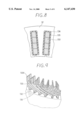
- a stator according to a second embodiment of the invention has four conductor segments 133 each of the slots as shown in FIG. 8.
- Four conductor segments 133 are lined up in the radial direction in each of slots 135 and connected in the manner illustrated in FIG. 9.
- Each of four conductor segments 133 extends from one of slots 135 in the alternately opposite direction.
- Conductor segments 133 on this side of FIG. 9 extend clockwise and those on the opposite side extend counterclockwise.
- End portion 133d of one conductor segment 133 is connected to end portion 133d of another conductor segment 133 spaced apart at a certain pitch.
- FIG. 9 illustrates a portion of stator opposite the end from where conductor segments are inserted and folded lips 136 of insulators 134.
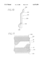
- FIG. 10 is a perspective view which illustrates I-shaped or J-shaped conductor segment 233.
- Conductor segment 233 has straight inside portion 233h and outside portions 233i extending outward from opposite ends of inside portion 233h.
- One of outside portions 233i is bent from the dotted state. End portion 233d of one conductor segment 233 is connected to end portion 233d of another conductor segment 233 disposed in another slot to form a stator winding.
- Conductor segments 233 are simple in shape and easy to manufacture. Because each of conductor segments 233 corresponds to one of insulators 34, it is easy to insert insulators 34 and conductor segments 233 into slots 35.
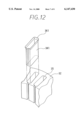
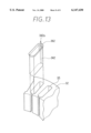
- Insulator 34 described above can be substituted by open insulator 341 having flared lip 361 shown in FIG. 12 or by closed insulator 342 having flared lip 362 shown in FIG. 13. Flared lips 361, 362 can be formed after the insulators are inserted into slots 35 easily without interference with each other. Each of flared lips 361 and 362 functions as a stopper to prevent the insulator from being dragged into slot 35 when conductor segment 33 is fully inserted into slot 35.
- overlapping portion 342a of closed insulator 342 is disposed remote from the opening of slot 35. This structure is effective to shut out water.
Abstract
In a stator of an ac generator for vehicle, a plurality of insulators are disposed in the slots of the stator to insulate the stator winding from the stator core. Each of the insulators has a smooth edge at one end and a stopper portion at the other end. The stopper portions project from an axial end of the stator core from which conductor segments of the stator winding are inserted. The conductor segments can be inserted into the slots with the smooth edges being at the head and can be easily positioned in the slots by the stopper.
Description
The present application is based on and claims priority from Japanese Patent Applications Hei 10-143008 filed on May 25, 1998 and Hei 10-180755 filed on Jun. 26, 1998, the contents of which are incorporated herein by reference.
1. Field of the Invention
The present invention relates to an ac generator for a passenger car, a track, or other vehicles that is driven by an internal combustion engine.
2. Description of the Related Art
It is known that a stator winding of an ac generator for a vehicle is formed of a plurality of conductor segments which are welded together. WO92/06527 discloses an example of such a stator winding, in which each of the conductor segments is inserted from one end of the stator core, the ends of conductor segments are welded to one another at the other end of the stator core. Usually, insulators are inserted into slots of the stator core. JP-A-4-17539 discloses insulators, each of which has a U-shape cross section and folded lips formed at opposite ends thereof. The folded lips position the insulator in the slots easily.
However, it is difficult to insert the insulators into the slots because the insulator disclosed in JP-A-4-17539 has folded lips at opposite ends thereof. While it is easy to insert an insulator having no such folded lips into the slots, it is difficult to position such an insulator in the axial direction. If an attempt is made to fold an end of the insulators after the conductor segments are inserted into the slots, the folded portion may be damaged due to folding pressure. Thus, the conductor segments can not be insulated from the stator core very well by a single sheet of insulator film.
Therefore, an object of the invention is to provide an improved stator of an ac generator for a vehicle in which insulators can be installed and positioned easily without damage.
According to a main feature of the invention, each of a plurality of insulators disposed in slots has a smooth end portion extending from one axial end of the stator core and a stopper engaging the other axial end of the stator core.
In the ac generator, stator winding may be composed of a plurality of conductor segments having a U-turn portion disposed at one end of the stator core, and the stopper portion is disposed at the same end as the U-turn portion.
Other objects, features and characteristics of the present invention as well as the functions of related parts of the present invention will become clear from a study of the following detailed description, the appended claims and the drawings. In the drawings:
FIG. 1 is a cross-sectional view illustrating an ac generator for a vehicle according to a first embodiment of the invention;
FIG. 2 is a perspective view of a U-shaped conductor segment forming a part of a stator winding of the stator according to the first embodiment;
FIG. 3 is a fragmentary cross-sectional view of the stator according to the first embodiment;
FIG. 4 is a perspective view illustrating an insulator to be inserted into one of slots of a stator core of the stator according to the first embodiment;
FIG. 5A is a fragmentary side view of a portion of the stator core and an insulator, FIG. 5B is a fragmentary side view of a portion of the stator with conductor segments disposed in one of the slots;
FIG. 6 is a fragmentary side view of a portion of the stator according to the first embodiment of the invention;
FIG. 7 is a perspective view illustrating coil ends disposed at opposite ends of the stator according to the first embodiment;
FIG. 8 is a fragmentary cross-sectional view of a portion of the stator according to a second embodiment of the invention;
FIG. 9 is a fragmentary perspective view of the stator according to the second embodiment;
FIG. 10 is a perspective view illustrating a modified conductor segment;
FIG. 11 is a fragmentary view of the stator having a plurality of the modified conductor segments shown in FIG. 10;
FIG. 12 is a perspective view illustrating a variation of the insulator to be inserted into one of slots of a stator core of the stator according to the first embodiment; and
FIG. 13 is a perspective view illustrating a variation of an insulator to be inserted into one of slots of a stator core of the stator according to the first embodiment.
An embodiment of the present invention is described with reference to the appended drawings.
As shown in FIG. 1, ac generator 1 according to a first embodiment of the invention includes stator 2, rotor 3, frame 4, rectifier 5, etc.
Stator 2 is composed of stator core 32, a plurality of conductor segments 33 and a plurality of insulators 34. Stator core 32 is a lamination of steel plates having a number of slots formed inside thereof. The portion of conductor segments projecting from stator core 32 form coil ends 31.
Rotor 3 has field coil 8, a pair of pole cores 7, and shaft 6. Each of the pair of pole cores 7 has six claw pole pieces extending axially to enclose field coil 8. Field coil 8 is composed of a cylindrically-wound insulation-coated copper wire. Axial flow type cooling fan 11 is welded to the front side pole core 7 to supply cooling air from the front side thereof in both the radial and axial directions. Centrifugal cooling fan 12 is welded to the rear side pole core 7 to supply cooling air from the rear side thereof radially outward.
Frame 4 accommodates stator 2 and rotor 3 and supports rotor 3 to rotate with shaft 6. Stator 2 is fixed to frame 4 around the pair of pole cores 7 at a certain gap therefrom. Frame 4 has air discharge vents 42 at portions opposite coil ends 31 of stator 2 and air intake vents 41 at the axial ends thereof.
AC generator 1 described above is rotated in a certain direction by an engine (not shown) via a belt and a pulley 20. When field coil 8 is energized by an outside power source, pole cores 7 are excited so that the stator winding provides a three-phase ac voltage. Accordingly, rectifier 5 provides a certain amount of dc current at the output terminals.
As illustrated in FIG. 2, conductor segment 33 is a U-shaped member made of copper bar or plate. Conductor segment 33 has inner conductor portion 33a, outer conductor portion 33b and U-turn portion 33c. Each of inner conductor portion 33a and outer conductor portion 33b has straight inner portion disposed in slot 35 and outer portion disposed outside slot 35.
A pair of conductor segments 33 is disposed in each one of slots 35 and connected to one another in a well known manner to form the stator winding. As illustrated in FIG. 3, inner and outer conductor portions 33a, 33b of conductor segment 33 a rectangular cross-section. The circumferential sides of conductor segment 33 are longer than its radial sides. Conductor segments 33 are coated with insulation film 33i to insulates one segment from another. Insulators 34 insulate conductor segments 33 from the stator core 32.
Column-shaped insulator 34 is made of a resinous sheet, which is rolled to fit the slot as shown in FIG. 4. Insulator 34 has a smooth edge at one end and outwardly folded lip 36 at the other end thereof. Insulator 34 is inserted into slot 35 in the axial direction with the smooth edge being at the head. Folded lip 36 functions as a stopper or positioner of insulator 34. Insulator 34 is inserted into slot 35 until folded lip 36 engages an end of stator core 32 so that both ends of insulator 34 can project from stator core 32 as shown in FIG. 5A. Subsequently, conductor segments 33 are inserted therein as shown in FIG. 5B and welded to form stator winding. Accordingly, conductor segments 33 are insulated from edge portions of stator core 32 by the projected portions of insulator 34. Here, folded lip 36 of insulator 34 is disposed at the side of stator core 32 where U-turn portion 33c is located. In other words, conductor segments 33 are inserted in the same direction as insulators 34 are inserted.
As illustrated in FIG. 6, U-turn portions 33c are disposed at one axial end of stator core 32 and opposite ends 33d are disposed at the other end thereof. Each of conductor segments 33 has slant portion 33e forming coil end 31 at one end of stator core 2. Slant portions 33e of conductor segments 33 disposed in the outer layers extend in the same direction, while slant portions 33e disposed in the inner layers extend in the different direction. Ends 33d of conductor segments 33 are welded by ultrasonic wave welder or arc welder, or are soldered or mechanically connected.
As shown in FIG. 4, one of insulators 34 is inserted to each of slots 35. Conductor segments 33 are made of copper plates, each of which is bent by a press machine to form a U-shape. A number of U-shaped conductor segments 33 are lined up so that U-turn portions 33c can be disposed at the same end of stator core 32. Conductor segments 33 are press-fitted into respective slots 35 so that outer and inner conductor portions 33b, 33a can fit the parallel walls of slot 35 via insulators 34 on the opposite surfaces thereof. As shown in FIG. 3, outer conductor portions 33b are inserted into the inner side of slots 35 that are insulated by insulators 34, and inner conductor portions 33a are inserted into the outer side of slots 35. Thereafter, two end portions 33d are bent in the opposite directions respectively to connect to end portions 33d of other conductor segments 33 in different layers.
Because insulator 34 has folded lip 36 at one end thereof and the other smooth end, insulator 34 can be inserted into the slot very easily. Moreover, assembling tools can be arranged in the axial direction if insulators 34 are inserted in the same axial direction as conductor segments 33 are inserted.
Thus, folded lips 36 engage, as stoppers, the end of stator core 32 when conductor segments 33 are fully inserted into slots 35 to position insulators 34 correctly.
Folded lips 36 can be located opposite the U-turn portion or the end from which conductor segments 33 are inserted. Folded lips 36 protect insulators 34 from pressure applied when end portions 33d are bent.
The number of conductor segments in each of the slots can be increased. A stator according to a second embodiment of the invention has four conductor segments 133 each of the slots as shown in FIG. 8. Four conductor segments 133 are lined up in the radial direction in each of slots 135 and connected in the manner illustrated in FIG. 9. Each of four conductor segments 133 extends from one of slots 135 in the alternately opposite direction. Conductor segments 133 on this side of FIG. 9 extend clockwise and those on the opposite side extend counterclockwise. End portion 133d of one conductor segment 133 is connected to end portion 133d of another conductor segment 133 spaced apart at a certain pitch. One of conductor segments 133 in the innermost layer is connected to another in the second inner layer, and one of conductor segments 133 in the third layer is connected to another in the outermost layer. FIG. 9 illustrates a portion of stator opposite the end from where conductor segments are inserted and folded lips 136 of insulators 134.
U-shaped conductor segment 33 can be substituted by a pair of turn-less conductor segments, which is welded after being assembled. FIG. 10 is a perspective view which illustrates I-shaped or J-shaped conductor segment 233. Conductor segment 233 has straight inside portion 233h and outside portions 233i extending outward from opposite ends of inside portion 233h.
One of outside portions 233i is bent from the dotted state. End portion 233d of one conductor segment 233 is connected to end portion 233d of another conductor segment 233 disposed in another slot to form a stator winding. Conductor segments 233 are simple in shape and easy to manufacture. Because each of conductor segments 233 corresponds to one of insulators 34, it is easy to insert insulators 34 and conductor segments 233 into slots 35.
Insulator 34 described above can be substituted by open insulator 341 having flared lip 361 shown in FIG. 12 or by closed insulator 342 having flared lip 362 shown in FIG. 13. Flared lips 361, 362 can be formed after the insulators are inserted into slots 35 easily without interference with each other. Each of flared lips 361 and 362 functions as a stopper to prevent the insulator from being dragged into slot 35 when conductor segment 33 is fully inserted into slot 35.
As shown in FIG. 13, overlapping portion 342a of closed insulator 342 is disposed remote from the opening of slot 35. This structure is effective to shut out water.
In the foregoing description of the present invention, the invention has been disclosed with reference to specific embodiments thereof. It will, however, be evident that various modifications and changes may be made to the specific embodiments of the present invention without departing from the broader spirit and scope of the invention as set forth in the appended claims. Accordingly, the description of the present invention in this document is to be regarded in an illustrative, rather than restrictive, sense.
Claims (4)
1. A stator of an ac generator for vehicle comprising:
a stator core having a plurality of slots having an opening;
a plurality of insulation-film-coated conductor segments having a U-turn portion, a pair of straight portions disposed in said plurality of slots, each of said pair of straight portions having an end inserted from one end of said stator core into one of said plurality of slots; and
a plurality of column-shaped insulators disposed in said plurality of slots to insulate said conductor segments from said stator core, each of said plurality of insulators having an outer periphery fitted to one of said plurality of slots, a smooth end portion extending from another end of said stator core and a stopper portion engaging said one end of said stator core;
wherein said stopper portion comprises a flared lip member which gradually widens as said flared lip member extends from said one end of said stator core; and
wherein each of said insulators has an overlapping portion disposed remote from said opening of one of said plurality of slots.
2. The ac generator as claimed in claim 1, wherein each of said plurality of slots has parallel walls and each of said pair of straight portions fits said parallel wall of one of said slots via one of said insulators.
3. The ac generator as claimed in claim 1, wherein each of said plurality of slots is formed by side walls extending in the longitudinal direction of said stator core and said flared lip member gradually widens as it extends from said one end of said stator core and from all of said side walls.
4. The ac generator as claimed in claim 1, wherein all portions of said flared lip member gradually widens as said flared lip member extends from said one end of said stator core.
Applications Claiming Priority (4)
| Application Number | Priority Date | Filing Date | Title |
|---|---|---|---|
| JP10-143008 | 1998-05-25 | ||
| JP14300898 | 1998-05-25 | ||
| JP18075598A JP3899685B2 (en) | 1998-06-26 | 1998-06-26 | Stator for vehicle alternator and manufacturing method thereof |
| JP10-180755 | 1998-06-26 |
Publications (1)
| Publication Number | Publication Date |
|---|---|
| US6147430A true US6147430A (en) | 2000-11-14 |
Family
ID=26474837
Family Applications (1)
| Application Number | Title | Priority Date | Filing Date |
|---|---|---|---|
| US09/314,886 Expired - Lifetime US6147430A (en) | 1998-05-25 | 1999-05-19 | Stator of AC generator for vehicle |
Country Status (3)
| Country | Link |
|---|---|
| US (1) | US6147430A (en) |
| EP (1) | EP0961386B1 (en) |
| DE (1) | DE69904671T2 (en) |
Cited By (58)
| Publication number | Priority date | Publication date | Assignee | Title |
|---|---|---|---|---|
| US6400056B1 (en) * | 1999-04-14 | 2002-06-04 | Denso Corporation | Stator of rotary electric machine and method for making the same |
| US20020153801A1 (en) * | 2000-09-12 | 2002-10-24 | Hans-Dieter Siems | Insulation element and method for introducing winding elements into grooves on an armature |
| US6570284B1 (en) * | 2001-12-11 | 2003-05-27 | Black & Decker Inc. | Brushless motor having double insulation |
| US20030137204A1 (en) * | 2002-01-24 | 2003-07-24 | Visteon Global Technologies, Inc. | Automotive alternator stator assembly with rectangular continuous wire |
| US6700236B2 (en) * | 1999-11-30 | 2004-03-02 | Denso Corporation | Liquid-cooled vehicle rotary electric machine |
| US20040119362A1 (en) * | 2002-12-19 | 2004-06-24 | Neet Kirk E. | Stator winding having cascaded end loops |
| US20040189134A1 (en) * | 2003-03-28 | 2004-09-30 | Denso Corporation | Stator of dynamo-electric machine |
| US20040212268A1 (en) * | 2002-01-24 | 2004-10-28 | Visteon Global Technologies, Inc. | Automotive alternator stator assembly with rectangular continuous wire |
| US20050006979A1 (en) * | 2002-01-24 | 2005-01-13 | Neet Kirk E. | Stator assembly with cascaded winding and method of making same |
| US20050040277A1 (en) * | 2003-08-18 | 2005-02-24 | Electrolock, Inc. | Method and apparatus for creating, using, and dispensing tubes |
| US20050046297A1 (en) * | 2002-01-24 | 2005-03-03 | Hanyang Ben Chen | Stator winding having transitions |
| US20050062359A1 (en) * | 2003-03-14 | 2005-03-24 | Visteon Global Technologies, Inc. | Stator of a rotary electric machine having staked core teeth |
| US20050110360A1 (en) * | 2003-11-26 | 2005-05-26 | Visteon Global Technologies, Inc. | Alternator stator having a multiple filar construction to improve convective cooling |
| US20050280328A1 (en) * | 2004-06-16 | 2005-12-22 | Visteon Global Technologies, Inc. | Stator of a rotary electric machine having secured core slot insulators |
| US20060032040A1 (en) * | 2004-08-10 | 2006-02-16 | Neet Kirk E | Method of making cascaded multilayer stator winding with interleaved transitions |
| US20060032044A1 (en) * | 2004-07-21 | 2006-02-16 | Visteon Global Technologies, Inc. | Method of forming cascaded stator winding |
| US20070011422A1 (en) * | 2005-07-11 | 2007-01-11 | General Electric Company | Hierarchical state based migration of structured data |
| US20100244615A1 (en) * | 2009-03-31 | 2010-09-30 | Denso Corporation | Stator for rotary electric machine and method of manufacturing the stator |
| US20110298318A1 (en) * | 2010-06-08 | 2011-12-08 | Bradfield Michael D | Gravity Fed Oil Cooling for an Electric Machine |
| US20110298316A1 (en) * | 2010-06-08 | 2011-12-08 | Bradfield Michael D | Electric Machine Cooling System and Method |
| US8207647B2 (en) | 2003-09-05 | 2012-06-26 | Black & Decker Inc. | Power tools with motor having a multi-piece stator |
| US8395287B2 (en) | 2010-10-04 | 2013-03-12 | Remy Technologies, Llc | Coolant channels for electric machine stator |
| JP2013051750A (en) * | 2011-08-30 | 2013-03-14 | Toyota Motor Corp | Rotary electric machine |
| US8446056B2 (en) | 2010-09-29 | 2013-05-21 | Remy Technologies, Llc | Electric machine cooling system and method |
| US8482169B2 (en) | 2010-06-14 | 2013-07-09 | Remy Technologies, Llc | Electric machine cooling system and method |
| US8492952B2 (en) | 2010-10-04 | 2013-07-23 | Remy Technologies, Llc | Coolant channels for electric machine stator |
| US8497608B2 (en) | 2011-01-28 | 2013-07-30 | Remy Technologies, Llc | Electric machine cooling system and method |
| US8508085B2 (en) | 2010-10-04 | 2013-08-13 | Remy Technologies, Llc | Internal cooling of stator assembly in an electric machine |
| US8513840B2 (en) | 2010-05-04 | 2013-08-20 | Remy Technologies, Llc | Electric machine cooling system and method |
| US8519581B2 (en) | 2010-06-08 | 2013-08-27 | Remy Technologies, Llc | Electric machine cooling system and method |
| US8546982B2 (en) | 2011-07-12 | 2013-10-01 | Remy Technologies, Llc | Electric machine module cooling system and method |
| US8546983B2 (en) | 2010-10-14 | 2013-10-01 | Remy Technologies, Llc | Split drain system and method for an electric machine module |
| US8552600B2 (en) | 2010-06-14 | 2013-10-08 | Remy Technologies, Llc | Potted end turns of an electric machine |
| US8575814B2 (en) | 2011-03-18 | 2013-11-05 | Remy Technologies, Llc | Conductor insulation arrangement for electric machine winding |
| US8593021B2 (en) | 2010-10-04 | 2013-11-26 | Remy Technologies, Llc | Coolant drainage system and method for electric machines |
| US8614538B2 (en) | 2010-06-14 | 2013-12-24 | Remy Technologies, Llc | Electric machine cooling system and method |
| US8624452B2 (en) | 2011-04-18 | 2014-01-07 | Remy Technologies, Llc | Electric machine module cooling system and method |
| US8648506B2 (en) | 2010-11-09 | 2014-02-11 | Remy Technologies, Llc | Rotor lamination cooling system and method |
| US8659190B2 (en) | 2010-06-08 | 2014-02-25 | Remy Technologies, Llc | Electric machine cooling system and method |
| US8659191B2 (en) | 2010-05-18 | 2014-02-25 | Remy Technologies, Llc | Sleeve member for an electric machine |
| US20140062250A1 (en) * | 2012-08-29 | 2014-03-06 | Denso Corporation | Rotary electric machine |
| US20140084740A1 (en) * | 2012-09-25 | 2014-03-27 | Remy Technologies, L.L.C. | Slot liner for electro-dynamic machine |
| US8692425B2 (en) | 2011-05-10 | 2014-04-08 | Remy Technologies, Llc | Cooling combinations for electric machines |
| US8803381B2 (en) | 2011-07-11 | 2014-08-12 | Remy Technologies, Llc | Electric machine with cooling pipe coiled around stator assembly |
| US8803380B2 (en) | 2011-06-03 | 2014-08-12 | Remy Technologies, Llc | Electric machine module cooling system and method |
| US8841811B2 (en) | 2010-08-18 | 2014-09-23 | Remy Technologies Llc | Conductor insulation arrangement for an electric machine |
| US8901789B2 (en) | 2011-10-07 | 2014-12-02 | Remy Technologies, Llc | Electric machine module |
| US8975792B2 (en) | 2011-09-13 | 2015-03-10 | Remy Technologies, Llc | Electric machine module cooling system and method |
| US9041260B2 (en) | 2011-07-08 | 2015-05-26 | Remy Technologies, Llc | Cooling system and method for an electronic machine |
| US9048710B2 (en) | 2011-08-29 | 2015-06-02 | Remy Technologies, Llc | Electric machine module cooling system and method |
| US9054565B2 (en) | 2010-06-04 | 2015-06-09 | Remy Technologies, Llc | Electric machine cooling system and method |
| US9099900B2 (en) | 2011-12-06 | 2015-08-04 | Remy Technologies, Llc | Electric machine module cooling system and method |
| US9130430B2 (en) | 2011-03-18 | 2015-09-08 | Remy Technologies Llc | Electric machine with fully enclosed in-slot conductors |
| JP2016019329A (en) * | 2014-07-07 | 2016-02-01 | 株式会社日本自動車部品総合研究所 | Stator for rotary electric machine |
| US9300178B2 (en) | 2012-08-10 | 2016-03-29 | Denso Corporation | Stator of electric rotating machine |
| US9331543B2 (en) | 2012-04-05 | 2016-05-03 | Remy Technologies, Llc | Electric machine module cooling system and method |
| US10069375B2 (en) | 2012-05-02 | 2018-09-04 | Borgwarner Inc. | Electric machine module cooling system and method |
| US10230281B2 (en) | 2013-08-08 | 2019-03-12 | Hitachi Automotive Systems, Ltd. | Rotating electrical machine |
Families Citing this family (9)
| Publication number | Priority date | Publication date | Assignee | Title |
|---|---|---|---|---|
| JP3310967B2 (en) | 1999-12-27 | 2002-08-05 | 三菱電機株式会社 | AC generator manufacturing method |
| DE60022973T2 (en) * | 1999-12-14 | 2006-07-20 | Mitsubishi Denki K.K. | Stator of an alternator for vehicles |
| JP2001211587A (en) * | 2000-01-21 | 2001-08-03 | Mitsubishi Electric Corp | Stator for rotary electric machine |
| DE10361670B4 (en) * | 2003-12-30 | 2009-08-06 | Mitsubishi Denki K.K. | Stator of a rotating electrical machine |
| US8595915B2 (en) | 2004-01-02 | 2013-12-03 | Mitsubishi Denki Kabushiki Kaisha | Stator of electric rotating machine |
| DE102017216164A1 (en) | 2017-09-13 | 2019-03-14 | Robert Bosch Gmbh | Rotor of an electric machine |
| JP6670279B2 (en) * | 2017-10-05 | 2020-03-18 | 本田技研工業株式会社 | Insulating paper and stator of rotating electric machine |
| DE102018219821A1 (en) * | 2018-11-19 | 2020-06-04 | Mahle International Gmbh | Insulation body for an electrical machine |
| WO2023061737A1 (en) * | 2021-10-11 | 2023-04-20 | Robert Bosch Gmbh | Slot liner for a rotor or stator of an electric machine |
Citations (25)
| Publication number | Priority date | Publication date | Assignee | Title |
|---|---|---|---|---|
| US1789128A (en) * | 1927-12-09 | 1931-01-13 | Vincent G Apple | Bar winding |
| US1822261A (en) * | 1927-06-28 | 1931-09-08 | Vincent G Apple | Bar wound field element |
| US1826295A (en) * | 1928-06-14 | 1931-10-06 | Vincent G Apple | Dynamo electric machine element |
| US1843591A (en) * | 1928-10-26 | 1932-02-02 | Vincent G Apple | Armature for dynamo electric machines |
| US2361842A (en) * | 1942-11-18 | 1944-10-31 | Jack & Heintz Inc | Armature construction |
| US2407935A (en) * | 1944-05-25 | 1946-09-17 | Chrysler Corp | Electrical machine |
| FR1091544A (en) * | 1954-01-19 | 1955-04-13 | Paris & Du Rhone | Insulating hood for notches of electrical machines |
| US2928963A (en) * | 1956-06-06 | 1960-03-15 | Gen Motors Corp | Dynamoelectric machine |
| GB1194085A (en) * | 1967-07-17 | 1970-06-10 | Gen Electric | Method and Apparatus for Producing and Inserting Insulation in the Slots of Magnetic Cores and Slot Liners for such Cores |
| US3634708A (en) * | 1970-05-04 | 1972-01-11 | Ibm | Improved low inertia armature winding formed of a continuous wire |
| US3745394A (en) * | 1967-07-17 | 1973-07-10 | Gen Electric | Electrical insulators for slotted magnetic cores |
| JPS5047102A (en) * | 1973-08-23 | 1975-04-26 | ||
| EP0006514A1 (en) * | 1978-06-23 | 1980-01-09 | Rapidsyn Co. | Method of assembly for electric motor stators |
| JPS58157349A (en) * | 1982-03-15 | 1983-09-19 | Toshiba Corp | Manufacture of insulated core for rotary electric machine |
| JPS59123330A (en) * | 1982-12-29 | 1984-07-17 | Fujitsu Ltd | Error detecting system |
| JPS59129548A (en) * | 1983-01-12 | 1984-07-25 | Nippon Denso Co Ltd | Armature for rotary electric machine |
| JPS6166553A (en) * | 1984-09-04 | 1986-04-05 | Mitsubishi Electric Corp | Manufacture of stator for canned motor |
| JPS62272836A (en) * | 1986-05-20 | 1987-11-27 | Nippon Denso Co Ltd | Armature coil |
| JPS63274335A (en) * | 1987-04-30 | 1988-11-11 | Nippon Denso Co Ltd | Armature coil |
| JPS645340A (en) * | 1987-06-25 | 1989-01-10 | Nippon Denso Co | Rotating electric machine |
| US5097167A (en) * | 1985-03-27 | 1992-03-17 | Nippondenso Co., Ltd. | Rotary electric machine coil assemblies |
| WO1992006527A1 (en) * | 1990-10-04 | 1992-04-16 | Robert Bosch Gmbh | Stator for electric motors and process for making it |
| JPH08205441A (en) * | 1995-01-23 | 1996-08-09 | Hitachi Ltd | Three-phase motor |
| US5587619A (en) * | 1992-12-21 | 1996-12-24 | Hitachi, Ltd. | Rotary armature and method of forming armature coil |
| US5845389A (en) * | 1994-06-04 | 1998-12-08 | Northrop Grumman Corporation | Method of fabricating a wound core |
Family Cites Families (1)
| Publication number | Priority date | Publication date | Assignee | Title |
|---|---|---|---|---|
| JPS59122330A (en) * | 1982-12-27 | 1984-07-14 | Hitachi Ltd | Slot insulator for rotary electric machine |
-
1999
- 1999-05-18 DE DE69904671T patent/DE69904671T2/en not_active Expired - Lifetime
- 1999-05-18 EP EP99109772A patent/EP0961386B1/en not_active Expired - Lifetime
- 1999-05-19 US US09/314,886 patent/US6147430A/en not_active Expired - Lifetime
Patent Citations (25)
| Publication number | Priority date | Publication date | Assignee | Title |
|---|---|---|---|---|
| US1822261A (en) * | 1927-06-28 | 1931-09-08 | Vincent G Apple | Bar wound field element |
| US1789128A (en) * | 1927-12-09 | 1931-01-13 | Vincent G Apple | Bar winding |
| US1826295A (en) * | 1928-06-14 | 1931-10-06 | Vincent G Apple | Dynamo electric machine element |
| US1843591A (en) * | 1928-10-26 | 1932-02-02 | Vincent G Apple | Armature for dynamo electric machines |
| US2361842A (en) * | 1942-11-18 | 1944-10-31 | Jack & Heintz Inc | Armature construction |
| US2407935A (en) * | 1944-05-25 | 1946-09-17 | Chrysler Corp | Electrical machine |
| FR1091544A (en) * | 1954-01-19 | 1955-04-13 | Paris & Du Rhone | Insulating hood for notches of electrical machines |
| US2928963A (en) * | 1956-06-06 | 1960-03-15 | Gen Motors Corp | Dynamoelectric machine |
| GB1194085A (en) * | 1967-07-17 | 1970-06-10 | Gen Electric | Method and Apparatus for Producing and Inserting Insulation in the Slots of Magnetic Cores and Slot Liners for such Cores |
| US3745394A (en) * | 1967-07-17 | 1973-07-10 | Gen Electric | Electrical insulators for slotted magnetic cores |
| US3634708A (en) * | 1970-05-04 | 1972-01-11 | Ibm | Improved low inertia armature winding formed of a continuous wire |
| JPS5047102A (en) * | 1973-08-23 | 1975-04-26 | ||
| EP0006514A1 (en) * | 1978-06-23 | 1980-01-09 | Rapidsyn Co. | Method of assembly for electric motor stators |
| JPS58157349A (en) * | 1982-03-15 | 1983-09-19 | Toshiba Corp | Manufacture of insulated core for rotary electric machine |
| JPS59123330A (en) * | 1982-12-29 | 1984-07-17 | Fujitsu Ltd | Error detecting system |
| JPS59129548A (en) * | 1983-01-12 | 1984-07-25 | Nippon Denso Co Ltd | Armature for rotary electric machine |
| JPS6166553A (en) * | 1984-09-04 | 1986-04-05 | Mitsubishi Electric Corp | Manufacture of stator for canned motor |
| US5097167A (en) * | 1985-03-27 | 1992-03-17 | Nippondenso Co., Ltd. | Rotary electric machine coil assemblies |
| JPS62272836A (en) * | 1986-05-20 | 1987-11-27 | Nippon Denso Co Ltd | Armature coil |
| JPS63274335A (en) * | 1987-04-30 | 1988-11-11 | Nippon Denso Co Ltd | Armature coil |
| JPS645340A (en) * | 1987-06-25 | 1989-01-10 | Nippon Denso Co | Rotating electric machine |
| WO1992006527A1 (en) * | 1990-10-04 | 1992-04-16 | Robert Bosch Gmbh | Stator for electric motors and process for making it |
| US5587619A (en) * | 1992-12-21 | 1996-12-24 | Hitachi, Ltd. | Rotary armature and method of forming armature coil |
| US5845389A (en) * | 1994-06-04 | 1998-12-08 | Northrop Grumman Corporation | Method of fabricating a wound core |
| JPH08205441A (en) * | 1995-01-23 | 1996-08-09 | Hitachi Ltd | Three-phase motor |
Non-Patent Citations (8)
| Title |
|---|
| Patent Abstracts of Japan vol. 007, No. 280 (E 216), Dec. 14, 1983 (1983 12 14) & JP 58 157349 A (Tokyo Shibaura Denki KK), Sep. 19, 1983 (1983 09 19). * |
| Patent Abstracts of Japan vol. 007, No. 280 (E-216), Dec. 14, 1983 (1983-12-14) & JP 58 157349 A (Tokyo Shibaura Denki KK), Sep. 19, 1983 (1983-09-19). |
| Patent Abstracts of Japan vol. 008, No. 256 (E 280), Nov. 22, 1984 (1984 11 22) & JP 59 129548 A (Nippon Denso KK), Jul. 25, 1984 (1984 07 25). * |
| Patent Abstracts of Japan vol. 008, No. 256 (E 280), Nov. 8, 1984 (1984 11 08) & JP 59 123330 A (Hitachi Seisakusho KK), Jul. 14, 1984 (1984 07 14). * |
| Patent Abstracts of Japan vol. 008, No. 256 (E-280), Nov. 22, 1984 (1984-11-22) & JP 59 129548 A (Nippon Denso KK), Jul. 25, 1984 (1984-07-25). |
| Patent Abstracts of Japan vol. 008, No. 256 (E-280), Nov. 8, 1984 (1984-11-08) & JP 59 123330 A (Hitachi Seisakusho KK), Jul. 14, 1984 (1984-07-14). |
| Patent Abstracts of Japan vol. 010, No. 233 (E 247), Aug. 13, 1986 (1986 08 13) & JP 61 066553 A (Mitsubishi Electric Corp), Apr. 5, 1986 (1986 04 05). * |
| Patent Abstracts of Japan vol. 010, No. 233 (E-247), Aug. 13, 1986 (1986-08-13) & JP 61 066553 A (Mitsubishi Electric Corp), Apr. 5, 1986 (1986-04-05). |
Cited By (82)
| Publication number | Priority date | Publication date | Assignee | Title |
|---|---|---|---|---|
| US6400056B1 (en) * | 1999-04-14 | 2002-06-04 | Denso Corporation | Stator of rotary electric machine and method for making the same |
| US6609289B2 (en) * | 1999-04-14 | 2003-08-26 | Denso Corporation | Stator of rotary electric machine and method for making the same |
| US6700236B2 (en) * | 1999-11-30 | 2004-03-02 | Denso Corporation | Liquid-cooled vehicle rotary electric machine |
| US6756716B2 (en) * | 2000-09-12 | 2004-06-29 | Robert Bosch Gmbh | Insulation element and method for introducing winding elements into grooves on an armature |
| US20020153801A1 (en) * | 2000-09-12 | 2002-10-24 | Hans-Dieter Siems | Insulation element and method for introducing winding elements into grooves on an armature |
| US6570284B1 (en) * | 2001-12-11 | 2003-05-27 | Black & Decker Inc. | Brushless motor having double insulation |
| US7170211B2 (en) | 2002-01-24 | 2007-01-30 | Visteon Global Technologies, Inc. | Stator winding having transitions |
| US20030137204A1 (en) * | 2002-01-24 | 2003-07-24 | Visteon Global Technologies, Inc. | Automotive alternator stator assembly with rectangular continuous wire |
| US6759779B2 (en) | 2002-01-24 | 2004-07-06 | Visteon Global Technologies, Inc. | Automotive alternator stator assembly with rectangular continuous wire |
| US20070018527A1 (en) * | 2002-01-24 | 2007-01-25 | Visteon Global Technologies, Inc. | Stator assembly with cascaded winding and method of making same |
| US20040212268A1 (en) * | 2002-01-24 | 2004-10-28 | Visteon Global Technologies, Inc. | Automotive alternator stator assembly with rectangular continuous wire |
| US7679253B2 (en) | 2002-01-24 | 2010-03-16 | Visteon Global Technologies, Inc. | Stator assembly with cascaded winding and method of making same |
| US20050006979A1 (en) * | 2002-01-24 | 2005-01-13 | Neet Kirk E. | Stator assembly with cascaded winding and method of making same |
| US7129612B2 (en) | 2002-01-24 | 2006-10-31 | Visteon Global Technologies, Inc. | Stator assembly with cascaded winding and method of making same |
| US20050046297A1 (en) * | 2002-01-24 | 2005-03-03 | Hanyang Ben Chen | Stator winding having transitions |
| US6862797B2 (en) | 2002-01-24 | 2005-03-08 | Viston Global Technologies, Inc. | Automotive alternator stator assembly with rectangular continuous wire |
| US6882077B2 (en) | 2002-12-19 | 2005-04-19 | Visteon Global Technologies, Inc. | Stator winding having cascaded end loops |
| US20040119362A1 (en) * | 2002-12-19 | 2004-06-24 | Neet Kirk E. | Stator winding having cascaded end loops |
| US6885124B2 (en) | 2003-03-14 | 2005-04-26 | Visteon Global Technologies, Inc. | Stator winding having radial aligned wraps |
| US20040263016A1 (en) * | 2003-03-14 | 2004-12-30 | Visteon Global Technologies, Inc. | Stator winding having radial aligned wraps |
| US6949857B2 (en) | 2003-03-14 | 2005-09-27 | Visteon Global Technologies, Inc. | Stator of a rotary electric machine having stacked core teeth |
| US20050062359A1 (en) * | 2003-03-14 | 2005-03-24 | Visteon Global Technologies, Inc. | Stator of a rotary electric machine having staked core teeth |
| US20040189134A1 (en) * | 2003-03-28 | 2004-09-30 | Denso Corporation | Stator of dynamo-electric machine |
| US6972506B2 (en) * | 2003-03-28 | 2005-12-06 | Denso Corporation | Stator of dynamo-electric machine |
| US7472724B2 (en) | 2003-08-18 | 2009-01-06 | Electrolock, Inc. | Method and apparatus for creating, using, and dispensing tubes |
| US20050040277A1 (en) * | 2003-08-18 | 2005-02-24 | Electrolock, Inc. | Method and apparatus for creating, using, and dispensing tubes |
| US8207647B2 (en) | 2003-09-05 | 2012-06-26 | Black & Decker Inc. | Power tools with motor having a multi-piece stator |
| US8558420B2 (en) | 2003-09-05 | 2013-10-15 | Black & Decker Inc. | Power tool with motor having a multi-piece stator |
| US6930426B2 (en) | 2003-11-26 | 2005-08-16 | Visteon Global Technologies, Inc. | Alternator stator having a multiple filar construction to improve convective cooling |
| US20050110360A1 (en) * | 2003-11-26 | 2005-05-26 | Visteon Global Technologies, Inc. | Alternator stator having a multiple filar construction to improve convective cooling |
| US20050280328A1 (en) * | 2004-06-16 | 2005-12-22 | Visteon Global Technologies, Inc. | Stator of a rotary electric machine having secured core slot insulators |
| US7042129B2 (en) | 2004-06-16 | 2006-05-09 | Visteon Global Technologies, Inc. | Stator of a rotary electric machine having secured core slot insulators |
| US7386931B2 (en) | 2004-07-21 | 2008-06-17 | Visteon Global Technologies, Inc. | Method of forming cascaded stator winding |
| US20060032044A1 (en) * | 2004-07-21 | 2006-02-16 | Visteon Global Technologies, Inc. | Method of forming cascaded stator winding |
| US7269888B2 (en) | 2004-08-10 | 2007-09-18 | Visteon Global Technologies, Inc. | Method of making cascaded multilayer stator winding with interleaved transitions |
| US20060032040A1 (en) * | 2004-08-10 | 2006-02-16 | Neet Kirk E | Method of making cascaded multilayer stator winding with interleaved transitions |
| US20070011422A1 (en) * | 2005-07-11 | 2007-01-11 | General Electric Company | Hierarchical state based migration of structured data |
| US20100244615A1 (en) * | 2009-03-31 | 2010-09-30 | Denso Corporation | Stator for rotary electric machine and method of manufacturing the stator |
| US8212449B2 (en) * | 2009-03-31 | 2012-07-03 | Denso Corporation | Stator for rotary electric machine and method of manufacturing the stator |
| US8513840B2 (en) | 2010-05-04 | 2013-08-20 | Remy Technologies, Llc | Electric machine cooling system and method |
| US8659191B2 (en) | 2010-05-18 | 2014-02-25 | Remy Technologies, Llc | Sleeve member for an electric machine |
| US9054565B2 (en) | 2010-06-04 | 2015-06-09 | Remy Technologies, Llc | Electric machine cooling system and method |
| US8269383B2 (en) * | 2010-06-08 | 2012-09-18 | Remy Technologies, Llc | Electric machine cooling system and method |
| US8456046B2 (en) * | 2010-06-08 | 2013-06-04 | Remy Technologies, Llc | Gravity fed oil cooling for an electric machine |
| US8659190B2 (en) | 2010-06-08 | 2014-02-25 | Remy Technologies, Llc | Electric machine cooling system and method |
| US20110298318A1 (en) * | 2010-06-08 | 2011-12-08 | Bradfield Michael D | Gravity Fed Oil Cooling for an Electric Machine |
| US8519581B2 (en) | 2010-06-08 | 2013-08-27 | Remy Technologies, Llc | Electric machine cooling system and method |
| US20110298316A1 (en) * | 2010-06-08 | 2011-12-08 | Bradfield Michael D | Electric Machine Cooling System and Method |
| US8614538B2 (en) | 2010-06-14 | 2013-12-24 | Remy Technologies, Llc | Electric machine cooling system and method |
| US8482169B2 (en) | 2010-06-14 | 2013-07-09 | Remy Technologies, Llc | Electric machine cooling system and method |
| US8552600B2 (en) | 2010-06-14 | 2013-10-08 | Remy Technologies, Llc | Potted end turns of an electric machine |
| US8841811B2 (en) | 2010-08-18 | 2014-09-23 | Remy Technologies Llc | Conductor insulation arrangement for an electric machine |
| US8446056B2 (en) | 2010-09-29 | 2013-05-21 | Remy Technologies, Llc | Electric machine cooling system and method |
| US8508085B2 (en) | 2010-10-04 | 2013-08-13 | Remy Technologies, Llc | Internal cooling of stator assembly in an electric machine |
| US8395287B2 (en) | 2010-10-04 | 2013-03-12 | Remy Technologies, Llc | Coolant channels for electric machine stator |
| US8492952B2 (en) | 2010-10-04 | 2013-07-23 | Remy Technologies, Llc | Coolant channels for electric machine stator |
| US8593021B2 (en) | 2010-10-04 | 2013-11-26 | Remy Technologies, Llc | Coolant drainage system and method for electric machines |
| US8546983B2 (en) | 2010-10-14 | 2013-10-01 | Remy Technologies, Llc | Split drain system and method for an electric machine module |
| US8648506B2 (en) | 2010-11-09 | 2014-02-11 | Remy Technologies, Llc | Rotor lamination cooling system and method |
| US8497608B2 (en) | 2011-01-28 | 2013-07-30 | Remy Technologies, Llc | Electric machine cooling system and method |
| US8575814B2 (en) | 2011-03-18 | 2013-11-05 | Remy Technologies, Llc | Conductor insulation arrangement for electric machine winding |
| US9130430B2 (en) | 2011-03-18 | 2015-09-08 | Remy Technologies Llc | Electric machine with fully enclosed in-slot conductors |
| US8624452B2 (en) | 2011-04-18 | 2014-01-07 | Remy Technologies, Llc | Electric machine module cooling system and method |
| US8692425B2 (en) | 2011-05-10 | 2014-04-08 | Remy Technologies, Llc | Cooling combinations for electric machines |
| US8803380B2 (en) | 2011-06-03 | 2014-08-12 | Remy Technologies, Llc | Electric machine module cooling system and method |
| US9041260B2 (en) | 2011-07-08 | 2015-05-26 | Remy Technologies, Llc | Cooling system and method for an electronic machine |
| US8803381B2 (en) | 2011-07-11 | 2014-08-12 | Remy Technologies, Llc | Electric machine with cooling pipe coiled around stator assembly |
| US8546982B2 (en) | 2011-07-12 | 2013-10-01 | Remy Technologies, Llc | Electric machine module cooling system and method |
| US9048710B2 (en) | 2011-08-29 | 2015-06-02 | Remy Technologies, Llc | Electric machine module cooling system and method |
| JP2013051750A (en) * | 2011-08-30 | 2013-03-14 | Toyota Motor Corp | Rotary electric machine |
| US8975792B2 (en) | 2011-09-13 | 2015-03-10 | Remy Technologies, Llc | Electric machine module cooling system and method |
| US8901789B2 (en) | 2011-10-07 | 2014-12-02 | Remy Technologies, Llc | Electric machine module |
| US9099900B2 (en) | 2011-12-06 | 2015-08-04 | Remy Technologies, Llc | Electric machine module cooling system and method |
| US9331543B2 (en) | 2012-04-05 | 2016-05-03 | Remy Technologies, Llc | Electric machine module cooling system and method |
| US10069375B2 (en) | 2012-05-02 | 2018-09-04 | Borgwarner Inc. | Electric machine module cooling system and method |
| US9300178B2 (en) | 2012-08-10 | 2016-03-29 | Denso Corporation | Stator of electric rotating machine |
| US20140062250A1 (en) * | 2012-08-29 | 2014-03-06 | Denso Corporation | Rotary electric machine |
| US9590461B2 (en) * | 2012-08-29 | 2017-03-07 | Denso Corporation | Rotary electric machine |
| US8907541B2 (en) * | 2012-09-25 | 2014-12-09 | Remy Technologies, L.L.C. | Slot liner for electro-dynamic machine |
| US20140084740A1 (en) * | 2012-09-25 | 2014-03-27 | Remy Technologies, L.L.C. | Slot liner for electro-dynamic machine |
| US10230281B2 (en) | 2013-08-08 | 2019-03-12 | Hitachi Automotive Systems, Ltd. | Rotating electrical machine |
| JP2016019329A (en) * | 2014-07-07 | 2016-02-01 | 株式会社日本自動車部品総合研究所 | Stator for rotary electric machine |
Also Published As
| Publication number | Publication date |
|---|---|
| DE69904671D1 (en) | 2003-02-06 |
| EP0961386A1 (en) | 1999-12-01 |
| DE69904671T2 (en) | 2003-07-31 |
| EP0961386B1 (en) | 2003-01-02 |
Similar Documents
| Publication | Publication Date | Title |
|---|---|---|
| US6147430A (en) | Stator of AC generator for vehicle | |
| US6335583B1 (en) | Stator of vehicle AC generator and method of manufacturing the same | |
| US6208060B1 (en) | Stator of vehicle AC generator and method of manufacturing the same | |
| US6459186B1 (en) | AC generator for vehicles | |
| US6242836B1 (en) | Vehicle AC generators stator and method of manufacturing the same | |
| US7042129B2 (en) | Stator of a rotary electric machine having secured core slot insulators | |
| JP4609190B2 (en) | Rotating electric machine for vehicles | |
| EP1081830B1 (en) | Electric rotary machine having a plurality of conductor segments and method of manufacturing the same | |
| JP5268885B2 (en) | Stator used in multi-phase electric machine | |
| US9419484B2 (en) | Stator for rotating electric machine | |
| KR100367031B1 (en) | An a.c. generator for vehicle | |
| US6972506B2 (en) | Stator of dynamo-electric machine | |
| KR100385681B1 (en) | Stator for an automotive alternator | |
| US20030164656A1 (en) | Stator of vehicle AC generator | |
| US6971153B2 (en) | Method of manufacturing winding of rotary electric machine | |
| JP2000166152A (en) | Stator of ac generator for vehicle and its manufacture | |
| JP2006345671A (en) | Rotating electric machine for vehicle | |
| JP2002010555A (en) | Rotary electric machine for vehicle | |
| EP1179881B1 (en) | AC generator for vehicles | |
| JP4265058B2 (en) | Vehicle alternator stator | |
| JPH1175347A (en) | Alternating current generator for vehicle | |
| US20050146238A1 (en) | Stator of electric rotating machine | |
| JP4606746B2 (en) | AC generator | |
| JP3511948B2 (en) | Method for manufacturing vehicle alternator and stator used therein | |
| JP3478183B2 (en) | Vehicle alternator and stator manufacturing method used therefor |
Legal Events
| Date | Code | Title | Description |
|---|---|---|---|
| AS | Assignment |
Owner name: DENSO CORPORATION, JAPAN Free format text: ASSIGNMENT OF ASSIGNORS INTEREST;ASSIGNORS:KUSASE, SHIN;UMEDA, ATSUSHI;SHIGA, TSUTOMU;AND OTHERS;REEL/FRAME:010040/0763;SIGNING DATES FROM 19990426 TO 19990510 |
|
| STCF | Information on status: patent grant |
Free format text: PATENTED CASE |
|
| FEPP | Fee payment procedure |
Free format text: PAYOR NUMBER ASSIGNED (ORIGINAL EVENT CODE: ASPN); ENTITY STATUS OF PATENT OWNER: LARGE ENTITY |
|
| FPAY | Fee payment |
Year of fee payment: 4 |
|
| FPAY | Fee payment |
Year of fee payment: 8 |
|
| FPAY | Fee payment |
Year of fee payment: 12 |