US6137258A - System for speed-sensorless control of an induction machine - Google Patents
System for speed-sensorless control of an induction machine Download PDFInfo
- Publication number
- US6137258A US6137258A US09/178,760 US17876098A US6137258A US 6137258 A US6137258 A US 6137258A US 17876098 A US17876098 A US 17876098A US 6137258 A US6137258 A US 6137258A
- Authority
- US
- United States
- Prior art keywords
- rotor flux
- angle
- stator
- saliency
- saturation
- Prior art date
- Legal status (The legal status is an assumption and is not a legal conclusion. Google has not performed a legal analysis and makes no representation as to the accuracy of the status listed.)
- Expired - Lifetime
Links
- 230000006698 induction Effects 0.000 title claims abstract description 33
- 230000004907 flux Effects 0.000 claims abstract description 129
- 229920006395 saturated elastomer Polymers 0.000 claims abstract description 8
- 230000001052 transient effect Effects 0.000 claims description 24
- 230000009466 transformation Effects 0.000 claims description 17
- 238000000034 method Methods 0.000 claims description 16
- 238000013507 mapping Methods 0.000 claims description 6
- 230000001131 transforming effect Effects 0.000 claims description 3
- 238000002347 injection Methods 0.000 description 15
- 239000007924 injection Substances 0.000 description 15
- 238000010586 diagram Methods 0.000 description 8
- 238000013461 design Methods 0.000 description 3
- 230000004044 response Effects 0.000 description 3
- 238000004804 winding Methods 0.000 description 3
- 230000000694 effects Effects 0.000 description 2
- 238000001914 filtration Methods 0.000 description 2
- 239000011159 matrix material Substances 0.000 description 2
- 238000012986 modification Methods 0.000 description 2
- 230000004048 modification Effects 0.000 description 2
- 230000001360 synchronised effect Effects 0.000 description 2
- 238000012360 testing method Methods 0.000 description 2
- 230000003750 conditioning effect Effects 0.000 description 1
- 238000006880 cross-coupling reaction Methods 0.000 description 1
- 238000005259 measurement Methods 0.000 description 1
- 230000008520 organization Effects 0.000 description 1
- 230000001105 regulatory effect Effects 0.000 description 1
- 238000004088 simulation Methods 0.000 description 1
- 230000002459 sustained effect Effects 0.000 description 1
Images


Classifications
-
- H—ELECTRICITY
- H02—GENERATION; CONVERSION OR DISTRIBUTION OF ELECTRIC POWER
- H02P—CONTROL OR REGULATION OF ELECTRIC MOTORS, ELECTRIC GENERATORS OR DYNAMO-ELECTRIC CONVERTERS; CONTROLLING TRANSFORMERS, REACTORS OR CHOKE COILS
- H02P21/00—Arrangements or methods for the control of electric machines by vector control, e.g. by control of field orientation
- H02P21/14—Estimation or adaptation of machine parameters, e.g. flux, current or voltage
- H02P21/141—Flux estimation
-
- H—ELECTRICITY
- H02—GENERATION; CONVERSION OR DISTRIBUTION OF ELECTRIC POWER
- H02P—CONTROL OR REGULATION OF ELECTRIC MOTORS, ELECTRIC GENERATORS OR DYNAMO-ELECTRIC CONVERTERS; CONTROLLING TRANSFORMERS, REACTORS OR CHOKE COILS
- H02P21/00—Arrangements or methods for the control of electric machines by vector control, e.g. by control of field orientation
- H02P21/14—Estimation or adaptation of machine parameters, e.g. flux, current or voltage
- H02P21/18—Estimation of position or speed
-
- H—ELECTRICITY
- H02—GENERATION; CONVERSION OR DISTRIBUTION OF ELECTRIC POWER
- H02P—CONTROL OR REGULATION OF ELECTRIC MOTORS, ELECTRIC GENERATORS OR DYNAMO-ELECTRIC CONVERTERS; CONTROLLING TRANSFORMERS, REACTORS OR CHOKE COILS
- H02P21/00—Arrangements or methods for the control of electric machines by vector control, e.g. by control of field orientation
- H02P21/24—Vector control not involving the use of rotor position or rotor speed sensors
- H02P21/26—Rotor flux based control
-
- H—ELECTRICITY
- H02—GENERATION; CONVERSION OR DISTRIBUTION OF ELECTRIC POWER
- H02P—CONTROL OR REGULATION OF ELECTRIC MOTORS, ELECTRIC GENERATORS OR DYNAMO-ELECTRIC CONVERTERS; CONTROLLING TRANSFORMERS, REACTORS OR CHOKE COILS
- H02P6/00—Arrangements for controlling synchronous motors or other dynamo-electric motors using electronic commutation dependent on the rotor position; Electronic commutators therefor
- H02P6/14—Electronic commutators
- H02P6/16—Circuit arrangements for detecting position
- H02P6/18—Circuit arrangements for detecting position without separate position detecting elements
- H02P6/185—Circuit arrangements for detecting position without separate position detecting elements using inductance sensing, e.g. pulse excitation
Landscapes
- Engineering & Computer Science (AREA)
- Power Engineering (AREA)
- Control Of Ac Motors In General (AREA)
Abstract
A system for speed-sensorless control of an induction machine includes a flux regulator & torque current calculator for operating the machine in a heavily saturated state to produce a saturation induced saliency; a saliency tracker for tracking an angle of the saturation-induced saliency; a signal injector for injecting an AC signal aligned with a saliency axis; voltage and current determiners for determining stator voltages and currents; and a rotor flux calculator for using the saturation-induced saliency angle, the determined stator voltages, and the determined stator currents to determine a magnitude and a location of a rotor flux vector. The flux regulator & torque current calculator is adapted to use the rotor flux vector to control the induction machine.
Description
The present invention relates generally to highly accurate and robust control of induction machines from inverter drives without the use of rotor position or speed sensors for feedback. The terms "sensorless", "speed-sensorless", "transducerless", "tachless", and "encoderless" are all used interchangeably to describe such control methods.
Methods of achieving direct field orientation (DFO) of induction machines are described in Jansen et al., "Observer-Based Direct Field Orientation: Analysis and Comparison of Alternative Methods," IEEE Transactions on Industry Applications, Vol. 30, No. 4, July/August 1994, pp. 945-953. DFO is based upon estimation of either the rotor or stator flux from the terminal voltage and current. For rotor flux DFO systems, cross coupling between the torque current and rotor flux can be nearly eliminated by orienting the rotor flux as the d-axis reference frame with a rotor flux observer, and the torque command can be calculated using the estimated rotor flux from the observer to adjust the commanded rotor flux. A closed-loop rotor flux observer estimates flux primarily in the stationary frame and includes two open-loop rotor flux observers which are referred to as current and voltage models. The current model uses measured stator current and rotor position to produce a flux estimate, while the voltage model relies on the measured stator voltage and current. Jansen et. al. further describes a motor drive system including an induction motor driven by a current regulated pulse width modulating (PWM) amplifier, a torque and flux regulator, a synchronous-to-stationary frame transformation block, current sensors, voltage sensors, a three-two phase transformation block, a flux observer, stationary-to-synchronous frame transformation blocks, and a velocity observer.
A method for flux estimation in induction machines is described in Jansen et al., U.S. Pat. No. 5,559,419, issued Sep. 24, 1996, wherein AC drive power is supplied to stator windings at a fundamental drive frequency which is at a level sufficient to provide magnetic saturation in the stator and at a signal frequency which is substantially higher than the drive frequency and wherein the response of the stator windings is measured to determine the variation of the response as a function of time during operation of the motor to determine the angular position and/or the speed of the magnetic flux vector. More specifically, a heterodyne demodulator mixes a signal which is a function of the high signal frequency with the response from the stator windings to provide a signal indicative of the rotational position of the magnetic flux vector. A drawback of this embodiment is that the injected signal is a balanced rotating AC signal, which produces an undesirable torque ripple at the signal frequency.
A means of integrating the flux estimation scheme described in U.S. Pat. No. 5,559,419, with a DFO scheme to obtain wide-speed-range sensorless control down to and including sustained zero frequency operation, was demonstrated via simulation in Jansen et. al, "Transducerless Field Orientation Concepts Employing Saturation-induced Saliencies in Induction Machines," IEEE Transactions on Industry Applications, Vol. 32, No. 6, November/December 1996.
Blaschke et al., "Sensorless Direct Field Orientation at Zero Flux Frequency," IEEE-IAS Annual Meeting, October 1996, describes operating AC machines in a saturated condition and superimposing an AC test current vector on a command stator current vector. By injecting an AC test current on the rotor flux axis, the system of Blaschke et al. assumes that the rotor flux axis is aligned with the saliency axis. In practice, the two axes are not always sufficiently aligned. For many motor designs, especially with closed rotor slots, the rotor flux axis and the saliency axis may shift by up to 90 degrees when operating from no load to full load. A system that does not take this shift into account may not always be stable and may not always produce the desired torque and control performance.
Unlike the embodiment in U.S. Pat. No. 5,559,419 which tracks a saturation-induced variation in the stator transient inductance, the embodiment of Blaschke et al. attempts to track a saturation-induced variation in the magnetizing inductance. With most induction machines and with high frequency signal injection (>50 Hz), the effects of the variation in stator transient inductance due to saturation will greatly outweigh the effects of the variation in magnetizing inductance as seen by the injected AC signal from the stator terminals. Thus a scheme designed to track variations in stator transient inductance caused by saturation is more desirable as a general purpose means of achieving zero frequency tachless control.
It is therefore seen to be desirable to provide a speed-sensorless control system which provides robust control of an induction machine while maintaining rotor flux orientation even when the saliency axis is not aligned with the rotor flux axis, which also utilizes AC signal injection in such a manner as to minimize torque ripple and to track variations in the stator transient inductance.
Briefly, according to one embodiment of the present invention, a system for speed-sensorless control of an induction motor includes: a saliency tracker for tracking an angle of a saturation-induced saliency in a stator transient inductance, and a signal injector for adding an injected AC signal aligned with the saturation-induced tracked saliency angle to a fundamental AC signal.
The features of the invention believed to be novel are set forth with particularity in the appended claims. The invention itself, however, both as to organization and method of operation, together with further objects and advantages thereof, may best be understood by reference to the following description taken in conjunction with the accompanying drawings, where like numerals represent like components, in which:
FIG. 1 is a block diagram of one embodiment of a motor drive system of the present invention.
FIG. 2 is a block diagram of a rotor flux calculator for use in the embodiment of FIG. 1.
FIG. 3 is a block diagram of another embodiment of a motor drive system of the present invention.
FIG. 4 is a block diagram of another embodiment for a saliency tracker and rotor flux calculator of the present invention.
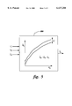
FIG. 5 is a graph representing an example rotor flux-to-saliency angle mapping table function.
One embodiment of the present invention is shown in the block diagram of the motor drive system of FIG. 1. FIG. 2 is a block diagram of a rotor flux calculator for use in the embodiment of FIG. 1. This invention can be used with speed-sensorless induction machines. Speed-sensorless means not requiring rotor position or speed sensors, and induction machine means machines capable of acting as induction motors and/or as induction generators. Although the invention is illustrated in FIG. 1 with voltage signal injection, current signal injection can alternatively be used, as discussed below. Additionally, although the Figures show separate blocks, in practice, a computer will perform the functions illustrated by the blocks digitally, with the exception of the voltage source inverter (VSI) 46. The invention is also applicable to analog implementations, as well as implementations combining analog and digital elements. Because the present invention involves operating the machine in a heavily saturated state, it is most useful when a machine is operating at frequencies in the range of zero (0) to about one (1) Hertz.
In FIG. 1, a system 10 for sensorless control of an induction machine 12 is shown as including a flux regulator & torque current calculator 14 for operating the motor in a heavily saturated state to produce a saturation induced saliency, a saliency tracker 16 for tracking an angle of the saturation-induced saliency in the stator transient inductance; a signal injector 18 for injecting an AC signal aligned with a saliency axis; voltage and current determiners 21 for determining stator voltages and currents; and a rotor flux calculator 26 for determining a magnitude and a location of a rotor flux vector. The rotor flux calculator may comprise any conventional rotor flux calculator such as a rotor flux observer or a rotor flux estimator, and the present invention is not intended to be limited to the specific rotor flux observer embodiment of FIG. 2 that is provided for purposes of example. The flux regulator & torque current calculator is adapted to use this rotor flux vector to control the induction motor. Also shown in FIG. 1 are associated transformation blocks, regulators, and filters.
The method of signal injection and demodulation for saliency tracking, coupled with a dynamically adjusted rotor flux calculator such as shown in FIG. 2, enables sensorless control over a wide speed range, including zero frequency, with low torque ripple.
In the present invention, the command signal components of stator voltage are supplied to respective adders 58 and 60 where respective injected signal voltage components vdsi rf* and vqsi rf* are added to provide command stator voltages vds rf* and vqs rf* in the rotor flux frame. Transformation block 62 rotates the command stator voltages (in the rotor flux frame) from the synchronous to the stationary frame and thereby converts them to command stator voltages vds s* and vqs s* in the stator frame which are then used by PWM VSI 46 to control induction machine 12.
If desired, voltage and current determiners 21 may comprise stator current and voltage sensors 22 and 20 respectively which sense motor line stator current and voltage signals and send the signals to feedback transformation block 24 which includes signal conditioning elements such as anti-aliasing filters and a three phase to two phase transformation element to provide two phase stationary stator frame determined voltage signals vds s and vqs s and determined current signals ids s and iqs s. Although voltage and current sensors and a feedback transformation block are shown in FIG. 1, these elements are not needed. For example, their values can be estimated in control hardware or software (shown as controller 321 in FIG. 3) as discussed for example in Y. Xue et al., "A Stator Flux-Oriented Voltage Source Variable-Speed Drive Based on dc Link Measurement", IEEE Transactions on Industry Applications, Vol. 27, No. 5, September/October 1991, pp. 962-969. In another example, the command values such as vds s* and vqs s* can be used as inputs to rotor flux calculator 26.
The two phase stationary frame (stator frame) current signals are transmitted to transformation block 62 which transforms them into signals ids rf and iqs rf in the rotor flux frame. Optional low pass filters 48 and 50 attenuate the signal component to minimize distortion of the injected AC signal voltages and provide the aforementioned respective fundamental components idsf rf and iqsf rf of the stator current in the rotor flux frame for subtraction by subtractors 54 and 56.
The two phase stationary frame determined current signals are additionally transmitted to saliency tracker 16 which determines the angle of the rotating saliency axis. AC signal injection is chosen along the saliency-axis to minimize undesirable torque ripple since the saliency-axis is generally more closely aligned with the rotor flux-axis than the orthogonal torque-axis. The low torque ripple feature makes the invention particularly suitable for high-power AC traction and industrial control systems. Such systems typically operate at low inverter switching frequencies (e.g., 300 Hz-2 kHz) which would restrict the AC signal injection frequency to be in a range (e.g., 30-300 Hz) that would otherwise be unacceptable if torque ripple was not abated.
The stator transient inductance matrix L.sub.σe of an induction motor with a saturation-induced saliency can be represented in the saliency reference frame of a two-phase model by: ##EQU1## where, because of saturation,
L.sub.σ.spsb.d ≠L.sub.σ.spsb.q (2)
and wherein:
L.sub.σ.spsb.d =d-axis stator transient inductance (saliency frame) and
L.sub.σ.spsb.q =q-axis stator transient inductance (saliency frame).
The stator transient inductance matrix L.sub.σe in a reference frame corresponding to an estimate of the saliency angular position can be shown to be ##EQU2## where ##EQU3## and
θ.sub.err =θ.sub.e -θ.sub.e, (6)
and wherein
θe is the actual saliency angular position, and
θe is the estimated saliency angular position.
The actual saliency angular position does not need to be directly determined. Instead, as discussed below with equation (24), an error is driven to zero such that the estimated saliency angular position tracks the actual saliency angular position.
With an injected signal frequency that is sufficiently high such that back-emf influence is negligible (i.e., ωi >>ωe), and a symmetrical rotor resistance, injected signal voltages vqsi e* and vdsi e* in the estimated saliency reference frame are approximately represented by vqsi e* and vdsi e* as follows:
v.sub.qsi.sup.e* ≡R.sub.σ i.sub.qsi.sup.e +[L.sub.σ +ΔL.sub.σ cos(2θ.sub.err)]pi.sub.qsi.sup.e -ΔL.sub.σ sin(2θ.sub.err)pi.sub.dsi.sup.e,(7)
and
v.sub.dsi.sup.e* ≡R.sub.σ i.sub.dsi.sup.e +[L.sub.σ -ΔL.sub.σ cos(2θ.sub.err)]pi.sub.dsi.sup.e -ΔL.sub.σ sin(2θ.sub.err)pi.sub.qsi.sup.e,(8)
where ##EQU4## wherein ωi =signal injection frequency (pθi),
ωe =actual saliency frequency,
ωe =estimated (tracked) saliency frequency,
R1 =stator resistance,
Lm =magnetizing inductance,
Lr =rotor inductance (sum of magnetizing and rotor leakage inductances),
R2 =rotor resistance,
p=time derivative operation; i.e., p=d/dt, and
iqsi e and idsi e =signal components of determined (feedback) stator currents in the estimated saliency frame (equation 20 calculates iqsi e)
Motor resistance and inductance values vary according to type of motor and mode of operation and can be determined by conventional control system techniques.
v.sub.qsi.sup.e* =0, (10)
and
v.sub.dsi.sup.e* =V.sub.dsi sin θ.sub.i (11)
where the instantaneous AC signal injection angle θi is
θ.sub.i =∫ω.sub.i dt. (12)
The resulting stator terminal voltages contain the following signal voltage components at the signal frequency in the saliency reference frame:
0≡R.sub.σ i.sub.qsi.sup.e +[L.sub.σ +ΔL.sub.σ cos(2θ.sub.err)]pi.sub.qsi.sup.e -ΔL.sub.σ sin(2θ.sub.err)pi.sub.dsi.sup.e, (13)
and
v.sub.dsi.sup.e ≡R.sub.σ i.sub.dsi.sup.e +[L.sub.σ -ΔL.sub.σ cos(2θ.sub.err)]pi.sub.dsi.sup.e -ΔL.sub.σ sin(2θ.sub.err)pi.sub.qsi.sup.e(14)
which solving for the q-axis signal current becomes: ##EQU5## where
pv.sub.dsi.sup.e =ω.sub.i V.sub.dsi cos θ.sub.i.(17)
Defining a modified transient impedance,
Z.sub.σ.sup.2 ·.tbd.·[R.sub.σ.sup.2 -(L.sub.σ.sup.2 -ΔL.sub.σ.sup.2)ω.sub.i.sup.2 +j2R.sub.σ L.sub.σ ω.sub.i ], (18)
wherein
R.sub.σ ·=·(mean) stator transient resistance, and a saturation-induced transient impedance,
ΔZ.sub.σ .tbd.ΔL.sub.σ ω.sub.i,(19)
equation (16) can be rewritten as ##EQU6## Multiplication of the q-axis signal current of equation (20) by -cos θi in cosine operator block 30 yields: ##EQU7## Low pass filtering εraw with low pass filter 32 to remove the twice signal frequency component (as well as the fundamental component of current) yields
ε=LPF(ε.sub.raw). (22) ##EQU8##
Equation (24), which is a mathematical equivalent of the signal which results from the motor drive system and from the synchronous transformation block 28, cosine operator block 30, and LPF 32 of the saliency tracker, thus describes an error signal that can be driven to zero via PI (proportional integral) controller 34 in the closed-loop saliency tracker to obtain ωe (the estimated (tracked) saliency frequency) which can then be converted to θe by integral block 36. The output of the tracker is then the estimated saliency angle θe which can be used by the rotor flux calculator. Frequency ωe is calculated as an optional intermediate quantity that can be utilized for rotor speed estimation or other well known control functions.
The tracked saliency angle θe feeds into rotor flux calculator (which is shown for purposes of example in FIG. 2 as a rotor flux observer 26). The two phase stationary frame determined voltage and current signals vds s, vqs s, ids s, and iqs s are additionally supplied to the rotor flux observer. A detailed description of a rotor flux observer 26 (for determining a magnitude and a location of a rotor flux vector) such as shown in FIG. 2 is provided in aforementioned Jansen et al., "Transducerless field orientation concepts employing saturation-induced saliencies in induction machines". The rotor flux observer preferably includes a voltage model 38, a universal current model 40 for using the determined stator currents and the saliency angle to determine a low frequency flux vector estimate, and a subtractor 42 for subtracting the rotor flux vector from the low frequency flux vector estimate to provide a vector difference. Proportional Integral controller 43 drives the vector difference to zero. The voltage model is adapted to use the output signal of the PI controller, the determined stator voltages, and the determined stator currents to determine the rotor flux vector λqr s,λdr s and the rotor flux angle θrf. The rotor flux angle is used by transformation block 62 and by subtractor 45/ signal injector 18.
The rotor flux observer includes a turn ratio mapper 44 for using a commanded rotor flux vector and a commanded rotor torque vector for determining a turn ratio for universal current model 40. The universal current model is adapted to use the turn ratio with the determined stator currents and the saliency angle to determine the low frequency flux vector estimate. The turn ratio mapper thus can dynamically adjust the universal current model with a motor/controller operating point to maintain the correct desired rotor flux output. The observer 26 tracks the voltage model flux estimate at high fundamental frequencies, and the current model flux estimate at zero and low frequencies (e.g., <4 Hz).
In most induction machines, the saliency angle will not be exactly aligned with the rotor flux. The actual alignment can vary significantly as a function of operating point, especially in machines with closed-rotor slots. Thus the turn-ratio a is dynamically adjusted based upon operating point to ensure that the output of the flux observer is rotor flux, independent of the tracked saliency angle. The variable turn-ratio a can be stored as a look-up table or a function that is determined prior to operation and is distinct for each motor design. As described in the aforementioned Jansen et al. article, one such function for aligning saliency with rotor flux is
a=Lm/Lr (25)
The tracked saliency angle θe additionally affects the angle of signal injector 18. As shown in FIG. 1, the tracked saliency is subtracted (with subtractor 45 which may be included in or separate from the signal injector) from the rotor flux angle θrf with the difference being used by the signal injector for transforming (via transformation block 64) the command signal components of the stator voltage in the saliency frame vdsi e*,vqsi e* into the command signal components of stator voltage in the rotor flux frame vdsi rf*,vqsi rf* (which, as discussed above, are added by elements 58 and 60 to the command fundamental components of stator voltage in the rotor flux frame).
Field orientation (i.e., torque & flux control in flux regulator and torque current calculator 14) is based upon rotor flux alignment, where the rotor flux angle is obtained from the rotor flux observer. Since the rotor flux angle is generally not aligned with the saliency angle, a rotation of the AC signal voltage commands from the saliency axis to the rotor flux axis is used as discussed. By injecting the AC signal in the saliency axis, the saliency tracking scheme is simplified over previous methods. Furthermore, unlike the aforementioned Blaschke et al. method wherein the AC signal is injected in the estimated rotor flux axis, rotor flux orientation is maintained even when the saliency axis is not aligned with the rotor flux axis through the use of the dynamically adjusted rotor flux observer. The injection in the saliency axis, when combined with the saliency tracker and the dynamically adjusted rotor flux observer, enables the system of the present invention to provide robust control on a wide variety of induction machine designs, provided that a detectable saturation-induced saliency is present, including machines with open and closed rotor slots.
FIG. 3 is a block diagram of another embodiment of a motor drive system 310 of the present invention. As discussed above, a direct field orientation scheme utilizing AC signal current injection rather than voltage is also possible. The implementation is similar to that shown in FIG. 1 with signal voltages and currents swapped in the saliency tracker and signal injection command block. The only other difference is that the signal current commands are added into subtractors 354 and 356 prior to the current regulator (I-Reg).
With signal current injection in the estimated saliency frame such that
i.sub.qsi.sup.e =0, (26)
and
i.sub.dsi.sup.e =I.sub.dsi sin θ.sub.i, (27)
where the instantaneous signal injection angle is
θ.sub.i =∫ω.sub.i dt, (28)
the signal voltages reduce to
v.sub.qsi.sup.e ≡-ΔL.sub.σ sin(2θ.sub.err)pi.sub.dsi.sup.e, (29)
and
v.sub.dsi.sup.e ≡R.sub.σ i.sub.dsi.sup.e +[L.sub.σ -ΔL.sub.σ cos(2θ.sub.err)]pi.sub.dsi.sup.e(30)
or
v.sub.qsi.sup.e ≡-ΔL.sub.σ sin(2θ.sub.err)ω.sub.i I.sub.dsi cos θ.sub.i,(31)
and
v.sub.dsi.sup.e ≡R.sub.σ I.sub.dsi sin ω.sub.i +[L.sub.σ -ΔL.sub.σ cos(2θ.sub.err)]ω.sub.i I.sub.dsi cos ω.sub.i. (32)
Multiplication of the q-axis signal voltage of equation (31) by -cos θi followed by low pass filtering to remove the twice signal frequency component (and fundamental) yields:
ε=LPF(·v.sub.qsi.sup.e cos θ.sub.i)≡1/2ΔL.sub.σ ω.sub.i I.sub.dsi sin[2(θ.sub.e -θ.sub.e)]. (33)
Thus with current injection, a similar error term is generated that when driven to zero via a PI controller will also yield the saliency angle.
FIG. 4 is a block diagram of another embodiment for a saliency tracker and rotor flux calculator of the present invention. In this embodiment, a rotor flux-to-saliency angle mapper 486 is present and integral in saliency tracker 416 and the estimated rotor flux angle θrf is used instead of the saliency angle θe as the input signal to universal current model 440 of rotor flux observer 426.
In this embodiment, controller 34, as discussed in FIG. 1, creates a signal ωrf (which is equal to ωe at steady state) to drive the error ε to zero which is then integrated by integral block 36 to provide rotor flux angle θrf. Rotor flux angle θrf can be used by mapper 486 to estimate the saliency angle θe which is supplied to transformation block 28 and which is subtracted with subtractor 446 from the rotor flux angle to provide a difference angle θ.sub.Δ which is used by transformation block 64 (shown in FIG. 1). The turn ratio (a) can be aligned with the rotor flux orientation in the universal current model by calculating it as Lm/Lr (the magnetizing inductance divided by the rotor inductance defined as the sum of magnetizing and rotor leakage inductances). By performing the mapping as part of the saliency tracking, a wider range of mapping can be performed.
FIG. 5 is a graph representing an example rotor flux-to-saliency angle mapping table function which can be used in mapper 486 of FIG. 4. The two curves in FIG. 5 represent a surface function of difference angle θ.sub.Δ with respect to T*e (commanded torque) and λ*r (commanded rotor flux magnitude). Once the difference angle is determined from the T*e and λ*r table or function, the saliency angle can be estimated by subtracting the difference angle from the rotor flux angle.
While only certain preferred features of the invention have been illustrated and described herein, many modifications and changes will occur to those skilled in the art. It is, therefore, to be understood that the appended claims are intended to cover all such modifications and changes as fall within the true spirit of the invention.
Claims (20)
1. A drive system for an induction machine comprising:
a saliency tracker for tracking an angle of a saturation-induced saliency in a stator transient inductance; and
a signal injector for aligning an injected AC signal with the tracked saturation-induced saliency angle and adding the aligned injected AC signal to a fundamental AC signal.
2. The system of claim 1 further comprising:
a field oriented system comprising a flux regulator & torque current calculator, a transformation block, and a PI current regulator for operating the machine in the heavily saturated state to produce the saturation induced saliency in the stator transient inductance;
voltage and current determiners for determining stator voltages and currents; and
a rotor flux calculator for using the tracked saturation-induced saliency angle, the determined stator voltages, and the determined stator currents to determine a magnitude and a location of a rotor flux vector,
wherein the flux regulator & torque current calculator is adapted to use the rotor flux vector to control the induction machine.
3. The system of claim 2 wherein the voltage and current determiners comprise voltage and current sensors for sensing machine line voltages and currents and a feedback transformation block for transforming the machine line voltages and currents to determined stator voltages and currents.
4. The system of claim 2 wherein at least one of the voltage and current determiners is implemented within control software and does not require a voltage or current sensor.
5. The system of claim 2 wherein the rotor flux calculator comprises a rotor flux observer.
6. The system of claim 1 wherein the injected AC signal comprises a voltage command.
7. The system of claim 1 wherein the injected AC signal comprises a current command.
8. The system of claim 1 wherein the saliency tracker is further for determining a rotor flux angle, and further comprising:
a field oriented system comprising a flux regulator & torque current calculator, a transformation block, and a PI current regulator for operating the machine in the heavily saturated state to produce the saturation induced saliency in the stator transient inductance;
voltage and current determiners for determining stator voltages and currents; and
a rotor flux calculator for using the rotor flux angle, the determined stator voltages, and the determined stator currents to determine a magnitude and a location of a rotor flux vector,
wherein the flux regulator & torque current calculator is adapted to use the rotor flux vector to control the induction machine.
9. The system of claim 8 wherein the rotor flux calculator comprises a rotor flux observer.
10. The system of claim 9 wherein the saliency tracker includes a rotor flux-to-saliency angle mapper.
11. A method for driving an induction machine comprising:
operating the machine in a heavily saturated state to produce a saturation induced saliency in the stator transient inductance;
tracking an angle of the saturation-induced saliency in the stator transient inductance;
aligning an injected AC signal with the tracked saturation-induced saliency angle; and
adding the aligned injected AC signal to a fundamental AC signal.
12. The method of claim 11 further including:
determining stator voltages and currents;
using the tracked saturation-induced saliency angle, the determined stator voltages, and the determined stator currents to determine a magnitude and a location of a rotor flux vector; and
using the rotor flux vector to control the induction machine.
13. The method of claim 12 wherein determining stator voltages and currents comprises sensing machine line voltages and currents and transforming the machine line voltages and currents to determined stator voltages and currents.
14. The method of claim 11 wherein adding an injected AC signal comprises adding an injected AC voltage command signal or an injected AC current command signal.
15. The method of claim 11 wherein tracking an angle of the saturation-induced saliency in the stator transient inductance includes determining a rotor flux angle, and further including:
determining stator voltages and currents;
using the rotor flux angle, the determined stator voltages, and the determined stator currents to determine a magnitude and a location of a rotor flux vector; and
using the rotor flux vector to control the induction machine.
16. The method of claim 15 wherein tracking the angle of the saturation-induced saliency in the stator transient inductance further includes mapping the rotor flux angle to the saturation-induced saliency angle.
17. A drive system for an induction machine comprising:
means for operating the machine in a heavily saturated state to produce a saturation induced saliency in the stator transient inductance;
means for tracking an angle of the saturation-induced saliency in the stator transient inductance; and
means aligning an injected AC signal with the tracked saturation-induced saliency angle and adding the aligned injected AC signal to a fundamental AC signal.
18. The system of claim 17 further including:
means for determining stator voltages and currents;
means for using the tracked saturation-induced saliency angle, the determined stator voltages, and the determined stator currents to determine a magnitude and a location of a rotor flux vector; and
means for using the rotor flux vector to control the induction machine.
19. The system of claim 17 wherein the means for tracking the angle of the saturation-induced saliency in the stator transient inductance includes means for determining a rotor flux angle, and further including:
means for determining stator voltages and currents;
means for using the rotor flux angle, the determined stator voltages, and the determined stator currents to determine a magnitude and a location of a rotor flux vector; and
means for using the rotor flux vector to control the induction machine.
20. The system of claim 19 wherein the means for tracking the angle of the saturation-induced saliency in the stator transient inductance further includes means for mapping between the rotor flux angle and the saturation-induced saliency angle.
Priority Applications (6)
| Application Number | Priority Date | Filing Date | Title |
|---|---|---|---|
| US09/178,760 US6137258A (en) | 1998-10-26 | 1998-10-26 | System for speed-sensorless control of an induction machine |
| AU62580/99A AU6258099A (en) | 1998-10-26 | 1999-09-21 | System for speed-sensorless control of an induction machine |
| CA002315396A CA2315396A1 (en) | 1998-10-26 | 1999-09-21 | System for speed-sensorless control of an induction machine |
| JP2000578901A JP2002529044A (en) | 1998-10-26 | 1999-09-21 | Speed sensorless induction machine control system |
| EP99949781A EP1044497A1 (en) | 1998-10-26 | 1999-09-21 | System for speed-sensorless control of an induction machine |
| PCT/US1999/021917 WO2000025418A1 (en) | 1998-10-26 | 1999-09-21 | System for speed-sensorless control of an induction machine |
Applications Claiming Priority (1)
| Application Number | Priority Date | Filing Date | Title |
|---|---|---|---|
| US09/178,760 US6137258A (en) | 1998-10-26 | 1998-10-26 | System for speed-sensorless control of an induction machine |
Publications (1)
| Publication Number | Publication Date |
|---|---|
| US6137258A true US6137258A (en) | 2000-10-24 |
Family
ID=22653856
Family Applications (1)
| Application Number | Title | Priority Date | Filing Date |
|---|---|---|---|
| US09/178,760 Expired - Lifetime US6137258A (en) | 1998-10-26 | 1998-10-26 | System for speed-sensorless control of an induction machine |
Country Status (6)
| Country | Link |
|---|---|
| US (1) | US6137258A (en) |
| EP (1) | EP1044497A1 (en) |
| JP (1) | JP2002529044A (en) |
| AU (1) | AU6258099A (en) |
| CA (1) | CA2315396A1 (en) |
| WO (1) | WO2000025418A1 (en) |
Cited By (78)
| Publication number | Priority date | Publication date | Assignee | Title |
|---|---|---|---|---|
| US6198248B1 (en) * | 1998-11-04 | 2001-03-06 | Alstom Enterprise Sa | Method of controlling a rotary electrical machine, a servo-control system for implementing the method, and a rotary machine fitted with such a system |
| US6329781B1 (en) * | 1999-02-08 | 2001-12-11 | Hitachi, Ltd. | Control apparatus of synchronous motors |
| US6377018B2 (en) * | 2000-03-10 | 2002-04-23 | Fuji Electric Co., Ltd. | Speed sensorless vector control apparatus |
| WO2002039575A2 (en) * | 2000-11-10 | 2002-05-16 | Otis Elevator Company | Method and apparatus for encoderless operation of a permanent magnet synchronous motor in an elevator |
| US6429616B1 (en) | 2001-03-29 | 2002-08-06 | Ford Global Technologies, Inc. | Method of estimating the DC bus voltage in electric machine drives |
| US6479971B1 (en) * | 1998-01-30 | 2002-11-12 | Schroedl Manfred | Method for regulating a three-phase machine without a mechanical rotary transducer |
| US6509711B1 (en) * | 2000-04-26 | 2003-01-21 | Ford Global Technologies, Inc. | Digital rotor flux observer |
| US20030065634A1 (en) * | 2001-07-18 | 2003-04-03 | Texas A&M University System | Method and system for determining induction motor speed |
| US6552508B1 (en) * | 2000-05-15 | 2003-04-22 | General Electric Co. | Apparatus and method for optimally controlling flux in an AC motor |
| US6552510B2 (en) * | 2000-12-22 | 2003-04-22 | Abb Oy | Method for frequency converter |
| US6559618B1 (en) * | 1999-07-29 | 2003-05-06 | Universita Degli Studi Di Catania | System and method of control for sensorless induction motor drives |
| US6605918B2 (en) * | 2001-08-31 | 2003-08-12 | Siemens Energy & Automation | System and method for compensating the reading of noncontinuous AC sinusoidal currents |
| US6639380B2 (en) | 2000-07-14 | 2003-10-28 | Sul Seung-Ki | Method and system of sensorless field orientation control for an AC motor |
| US20040007995A1 (en) * | 2002-07-11 | 2004-01-15 | Visteon Global Technologies, Inc. | Vector control system for permanent magnet sychronous machines using an open-loop parameter observer |
| US6683428B2 (en) | 2002-01-30 | 2004-01-27 | Ford Global Technologies, Llc | Method for controlling torque in a rotational sensorless induction motor control system with speed and rotor flux estimation |
| US20040046519A1 (en) * | 2002-09-11 | 2004-03-11 | Ford Global Technologies, Inc. | Diagnostic strategy for an electric motor using sensorless control and a position sensor |
| US20040056629A1 (en) * | 2000-11-09 | 2004-03-25 | Toshiyuki Maeda | Synchronous motor control method and device |
| US20040061472A1 (en) * | 2002-09-26 | 2004-04-01 | Lg Electronics Inc. | Apparatus for measuring magnetic flux of synchronous reluctance motor and sensorless control system for the same motor |
| US20040070362A1 (en) * | 2002-10-10 | 2004-04-15 | Patel Nitinkumar R. | Position sensorless control algorithm for AC machine |
| US6750628B2 (en) | 2001-12-03 | 2004-06-15 | Electric Boat Corporation | Flux shunt wave shape control arrangement for permanent magnet machines |
| US20040155620A1 (en) * | 2003-02-10 | 2004-08-12 | Myers Garold P. | Compensation method for current-sensor gain errors |
| US20040257028A1 (en) * | 2003-06-23 | 2004-12-23 | Schulz Steven E. | Position sensorless control algorithm for AC machine |
| US6838778B1 (en) | 2002-05-24 | 2005-01-04 | Hamilton Sundstrand Corporation | Integrated starter generator drive having selective torque converter and constant speed transmission for aircraft having a constant frequency electrical system |
| US6838779B1 (en) * | 2002-06-24 | 2005-01-04 | Hamilton Sundstrand Corporation | Aircraft starter generator for variable frequency (vf) electrical system |
| US20050029972A1 (en) * | 2003-05-19 | 2005-02-10 | Nobuyuki Imai | Control apparatus for brushless DC motor |
| US20050052177A1 (en) * | 2003-09-05 | 2005-03-10 | Antti Piippo | Method in salient-pole permanent magnet synchronous machine |
| US20050057208A1 (en) * | 2003-09-17 | 2005-03-17 | Seibel Brian J. | Method and apparatus to regulate loads |
| US6965212B1 (en) | 2004-11-30 | 2005-11-15 | Honeywell International Inc. | Method and apparatus for field weakening control in an AC motor drive system |
| US20060033457A1 (en) * | 2004-08-12 | 2006-02-16 | Lg Electronics Inc. | Sensorless motor drive apparatus and method for protecting and controlling the same |
| US20060038530A1 (en) * | 2004-07-07 | 2006-02-23 | Rt Patent Company, Inc. | System and method for optimizing motor performance by varying flux |
| US20060066275A1 (en) * | 2004-09-29 | 2006-03-30 | Thunes Jerry D | Method and apparatus to regulate torque provided to loads |
| EP1646138A1 (en) * | 2003-07-16 | 2006-04-12 | Mitsubishi Denki Kabushiki Kaisha | Device for estimating pole position of synchronous motor |
| US20060119305A1 (en) * | 2004-12-06 | 2006-06-08 | Lg Electronics Inc. | Method and device for controlling startup of motor |
| US20060119309A1 (en) * | 2004-12-08 | 2006-06-08 | Samsung Electronics Co., Ltd | Apparatus and method for controlling velocity of motor |
| US20060232237A1 (en) * | 2005-04-13 | 2006-10-19 | Schneider Toshiba Inverter Europe Sas | Method for adjusting parameters of an electric motor and variable speed drive using such a method |
| US7211984B2 (en) * | 2004-11-09 | 2007-05-01 | General Motors Corporation | Start-up and restart of interior permanent magnet machines |
| US20080048599A1 (en) * | 2006-07-13 | 2008-02-28 | Ho Eddy Y Y | Signal conditioning apparatus and method for determination of permanent magnet motor rotor position |
| US7342379B2 (en) | 2005-06-24 | 2008-03-11 | Emerson Electric Co. | Sensorless control systems and methods for permanent magnet rotating machines |
| US20090009701A1 (en) * | 2000-02-29 | 2009-01-08 | Akira Yamaguchi | Light Diffusing Plate and Display Apparatus |
| US20090128074A1 (en) * | 2007-11-16 | 2009-05-21 | Jun Hu | Initial rotor position detection and start-up system for a dynamoelectric machine |
| US20090212724A1 (en) * | 2008-02-21 | 2009-08-27 | Siemens Energy & Automation, Inc. | Method for Braking an AC Motor |
| US20090284212A1 (en) * | 2008-05-16 | 2009-11-19 | Square D Company | Methods and apparatuses for estimating transient slip |
| US7667423B2 (en) | 2005-06-24 | 2010-02-23 | Emerson Electric Co. | Control systems and methods for permanent magnet rotating machines |
| US20100134064A1 (en) * | 2008-12-01 | 2010-06-03 | Abb Oy | Method and apparatus for estimating a rotation speed of an electric motor |
| US20100194329A1 (en) * | 2009-01-30 | 2010-08-05 | Bin Lu | System and method for determining stator winding resistance in an ac motor using motor drives |
| US20100207555A1 (en) * | 2009-01-21 | 2010-08-19 | Young Doo Yoon | Alternating-current motor control apparatus |
| CN101986798A (en) * | 2008-02-21 | 2011-03-16 | 西门子工业公司 | Method and system for braking an AC motor |
| US20120068640A1 (en) * | 2010-09-16 | 2012-03-22 | Abb Technology Ag | Flux offset compensation for a rotating electrical machine |
| US20120143417A1 (en) * | 2010-12-01 | 2012-06-07 | Kia Motors Corporation | System for error detection of hybrid vehicle and method thereof |
| US20120153883A1 (en) * | 2009-09-02 | 2012-06-21 | Sew-Eurodrive Gmbh & Co. Kg | Method for Determining the Rotor Position of a Synchronous Machine Operated in Field-Oriented Manner |
| US20120169268A1 (en) * | 2010-12-30 | 2012-07-05 | Lsis Co., Ltd | System and method for controlling torque of induction motor in electric vehicle |
| US20130342142A1 (en) * | 2012-04-26 | 2013-12-26 | Emerson Climate Technologies, Inc. | System And Method for Permanent Magnet Motor Control |
| US20140070745A1 (en) * | 2011-05-10 | 2014-03-13 | Daisuke Hirono | Applied-Voltage Electrical Angle Setting Method For Synchronous Motor, And Motor Control Apparatus |
| US20140197765A1 (en) * | 2013-01-14 | 2014-07-17 | Samsung Electronics Co., Ltd. | Methods and apparatuses for controlling output voltages of inverters driving of electric motors |
| US20140300309A1 (en) * | 2013-04-04 | 2014-10-09 | Lsis Co., Ltd. | Sensorless vector control apparatus for induction motor |
| US20140346990A1 (en) * | 2013-05-21 | 2014-11-27 | IFP Energies Nouvelles | Method of determining the position and the speed of a rotor in a synchronous electric machine using state observers |
| WO2015013304A1 (en) | 2013-07-23 | 2015-01-29 | Atieva, Inc. | Induction motor flux and torque control |
| WO2015013361A1 (en) | 2013-07-23 | 2015-01-29 | Atieva, Inc. | Induction motor flux and torque control with rotor flux estimation |
| WO2014209742A3 (en) * | 2013-06-28 | 2015-04-16 | Eaton Corporation | System and method of rotor time constant online identification in an ac induction machine |
| US20150123577A1 (en) * | 2013-11-05 | 2015-05-07 | Denso Corporation | Control apparatus for ac motor |
| US20150180398A1 (en) * | 2013-07-23 | 2015-06-25 | Atieva, Inc. | Induction motor flux and torque control |
| EP2897282A1 (en) * | 2014-01-17 | 2015-07-22 | Kabushiki Kaisha Yaskawa Denki | Rotary electric machine controller, rotary electric machine control method, and method of creating control map |
| US9093878B2 (en) | 2012-11-01 | 2015-07-28 | General Electric Company | Sensorless electric machine |
| US20150311847A1 (en) * | 2014-04-29 | 2015-10-29 | Lsis Co., Ltd. | Rotation angle estimation module for sensorless vector control of pmsm |
| US9431949B2 (en) | 2014-04-29 | 2016-08-30 | General Electric Company | Induction motor speed estimation |
| US20160373043A1 (en) * | 2015-06-18 | 2016-12-22 | Kabushiki Kaisha Yaskawa Denki | Motor controller, flux command generator, and method for generating flux command |
| US9641033B2 (en) | 2013-09-06 | 2017-05-02 | General Electric Company | Electric machine having offset rotor sections |
| CN106936349A (en) * | 2015-12-24 | 2017-07-07 | 英飞凌科技股份有限公司 | By voltage vector angular deflection weak magnetic AC motor controls |
| US9705433B2 (en) | 2009-08-10 | 2017-07-11 | Emerson Climate Technologies, Inc. | Controller and method for transitioning between control angles |
| CN107359835A (en) * | 2017-08-28 | 2017-11-17 | 南京理工大学 | A kind of ultrahigh speed permagnetic synchronous motor method for controlling number of revolution based on adaptive robust control |
| US9871418B2 (en) | 2012-11-01 | 2018-01-16 | General Electric Company | Sensorless electric machine |
| US9906108B2 (en) | 2012-11-01 | 2018-02-27 | General Electric Company | Sensorless electric machine |
| US9906082B2 (en) | 2013-09-06 | 2018-02-27 | General Electric Company | Electric machine having reduced torque oscillations and axial thrust |
| US9941775B2 (en) | 2012-11-01 | 2018-04-10 | General Electric Company | D-ring implementation in skewed rotor assembly |
| US9948224B1 (en) | 2016-10-17 | 2018-04-17 | General Electric Company | System and method for sensorless control of electric machines using magnetic alignment signatures |
| CN110323982A (en) * | 2019-05-29 | 2019-10-11 | 长沙学院 | A kind of method for controlling permanent magnet synchronous motor considering cross-coupling and saturation effect |
| US11043912B2 (en) | 2018-09-20 | 2021-06-22 | Fca Us Llc | Sensorless position estimation for interior permanent magnet synchronous motor |
| US11177759B2 (en) * | 2018-11-28 | 2021-11-16 | General Electric Company | System and method for self-sensing of electric machines and reduction of noise and vibration associated therewith |
Families Citing this family (9)
| Publication number | Priority date | Publication date | Assignee | Title |
|---|---|---|---|---|
| DE10031637C1 (en) * | 2000-06-27 | 2002-01-31 | Daimler Chrysler Ag | Device for determining revolution rate of induction motor uses saliency tracking method with sensor for measuring electric current, signal processing arrangement integrated into sensor |
| US6301136B1 (en) * | 2000-07-19 | 2001-10-09 | Honeywell International Inc. | Floating flame controller |
| JP4539218B2 (en) * | 2004-08-02 | 2010-09-08 | 日本精工株式会社 | Electric power steering device |
| SE0801590L (en) * | 2008-07-03 | 2008-07-04 | Abb Research Ltd | Method for optimizing torque relative to current in electric motors |
| KR101549283B1 (en) * | 2011-10-12 | 2015-09-01 | 엘에스산전 주식회사 | Parameter estimating apparatus for permanent magnet synchronous motor driving system |
| CN111327243B (en) | 2018-12-13 | 2022-05-27 | 台达电子工业股份有限公司 | Rotating electric machine control device and control method thereof |
| TWI686047B (en) | 2018-12-13 | 2020-02-21 | 台達電子工業股份有限公司 | Device and method for controlling rotary electric machine |
| EP3902135B1 (en) * | 2020-04-20 | 2023-12-13 | ABB Schweiz AG | Angular position error estimation at standstill for high-frequency voltage injection |
| EP3982534A1 (en) * | 2020-10-12 | 2022-04-13 | Mitsubishi Electric R&D Centre Europe B.V. | Method and device for controlling an electrical motor |
Citations (7)
| Publication number | Priority date | Publication date | Assignee | Title |
|---|---|---|---|---|
| US4445080A (en) * | 1981-11-25 | 1984-04-24 | The Charles Stark Draper Laboratory, Inc. | System for indirectly sensing flux in an induction motor |
| DE4103270A1 (en) * | 1990-11-02 | 1992-05-07 | Abb Patent Gmbh | Stator flux evaluation system for rotary electrical machine - uses differential of difference winding inductances within saturation range |
| JPH08149898A (en) * | 1994-11-24 | 1996-06-07 | Hitachi Ltd | Control method for induction motor |
| US5559419A (en) * | 1993-12-22 | 1996-09-24 | Wisconsin Alumni Research Foundation | Method and apparatus for transducerless flux estimation in drives for induction machines |
| US5565752A (en) * | 1993-12-22 | 1996-10-15 | Wisconsin Alumni Research Foundation | Method and apparatus for transducerless position and velocity estimation in drives for AC machines |
| US5729113A (en) * | 1997-01-21 | 1998-03-17 | General Electric Company | Sensorless rotor velocity estimation for induction motors |
| US5796235A (en) * | 1991-04-11 | 1998-08-18 | Schrodl; Manfred | Process and circuits for determining machine-related electro-magnetic and mechanical state variables on electrodynamic induction machines supplied via converters |
Family Cites Families (1)
| Publication number | Priority date | Publication date | Assignee | Title |
|---|---|---|---|---|
| DE19532149A1 (en) * | 1995-08-31 | 1997-03-06 | Siemens Ag | Method and device for correcting a flow direction of a model flow of an encoderless, field-oriented rotating field machine up to frequency zero |
-
1998
- 1998-10-26 US US09/178,760 patent/US6137258A/en not_active Expired - Lifetime
-
1999
- 1999-09-21 WO PCT/US1999/021917 patent/WO2000025418A1/en active Application Filing
- 1999-09-21 JP JP2000578901A patent/JP2002529044A/en active Pending
- 1999-09-21 EP EP99949781A patent/EP1044497A1/en not_active Withdrawn
- 1999-09-21 AU AU62580/99A patent/AU6258099A/en not_active Abandoned
- 1999-09-21 CA CA002315396A patent/CA2315396A1/en not_active Abandoned
Patent Citations (8)
| Publication number | Priority date | Publication date | Assignee | Title |
|---|---|---|---|---|
| US4445080A (en) * | 1981-11-25 | 1984-04-24 | The Charles Stark Draper Laboratory, Inc. | System for indirectly sensing flux in an induction motor |
| DE4103270A1 (en) * | 1990-11-02 | 1992-05-07 | Abb Patent Gmbh | Stator flux evaluation system for rotary electrical machine - uses differential of difference winding inductances within saturation range |
| US5796235A (en) * | 1991-04-11 | 1998-08-18 | Schrodl; Manfred | Process and circuits for determining machine-related electro-magnetic and mechanical state variables on electrodynamic induction machines supplied via converters |
| US5559419A (en) * | 1993-12-22 | 1996-09-24 | Wisconsin Alumni Research Foundation | Method and apparatus for transducerless flux estimation in drives for induction machines |
| US5565752A (en) * | 1993-12-22 | 1996-10-15 | Wisconsin Alumni Research Foundation | Method and apparatus for transducerless position and velocity estimation in drives for AC machines |
| US5585709A (en) * | 1993-12-22 | 1996-12-17 | Wisconsin Alumni Research Foundation | Method and apparatus for transducerless position and velocity estimation in drives for AC machines |
| JPH08149898A (en) * | 1994-11-24 | 1996-06-07 | Hitachi Ltd | Control method for induction motor |
| US5729113A (en) * | 1997-01-21 | 1998-03-17 | General Electric Company | Sensorless rotor velocity estimation for induction motors |
Non-Patent Citations (12)
| Title |
|---|
| F. Blaschke, et al, "Sensorless Direct Field Orientation at Zero Flux Frequency", IEEE-IAS Meeting, Oct. 1996, pp. 189-196. |
| F. Blaschke, et al, Sensorless Direct Field Orientation at Zero Flux Frequency , IEEE IAS Meeting, Oct. 1996, pp. 189 196. * |
| PL Jansen, et al, "Observer-Based Direct Field Orientation: Analysis and Comparison of Alternative Methods", IEEE Trans. On Industry Applications, vol. 30, No. 4, Jul./Aug. 1994, pp. 945-953. |
| PL Jansen, et al, "Transducerless Field Orientation Concepts Employing Saturation-Induced Saliencies in Induction Machines", 1995 IEEE, pp. 174-181. |
| PL Jansen, et al, "Transducerless Field Orientation Concepts Employing Saturation-Induced Saliencies in Induction Machines", IEEE Trans on Industry Applications, vol. 32, No. 6, Nov./Dec. 1996, pp. 1380-1393. |
| PL Jansen, et al, "Transducerless Position and Velocity Estimation In Induction and Salient AC Machines", IEEEE-TAS Annual Meeting, Denver, Oct. 1994, pp. 488-495. |
| PL Jansen, et al, Observer Based Direct Field Orientation: Analysis and Comparison of Alternative Methods , IEEE Trans. On Industry Applications, vol. 30, No. 4, Jul./Aug. 1994, pp. 945 953. * |
| PL Jansen, et al, Transducerless Field Orientation Concepts Employing Saturation Induced Saliencies in Induction Machines , 1995 IEEE, pp. 174 181. * |
| PL Jansen, et al, Transducerless Field Orientation Concepts Employing Saturation Induced Saliencies in Induction Machines , IEEE Trans on Industry Applications, vol. 32, No. 6, Nov./Dec. 1996, pp. 1380 1393. * |
| PL Jansen, et al, Transducerless Position and Velocity Estimation In Induction and Salient AC Machines , IEEEE TAS Annual Meeting, Denver, Oct. 1994, pp. 488 495. * |
| Y. Xue, et al, "A Stator Flux-Oriented Voltage Source Variable-Speed Drive Based on dc Link Measurement", IEEE Trans. on Ind. Appl. vol. 27, No. 5, Sep./Oct. 1991, pp. 962-969. |
| Y. Xue, et al, A Stator Flux Oriented Voltage Source Variable Speed Drive Based on dc Link Measurement , IEEE Trans. on Ind. Appl. vol. 27, No. 5, Sep./Oct. 1991, pp. 962 969. * |
Cited By (139)
| Publication number | Priority date | Publication date | Assignee | Title |
|---|---|---|---|---|
| US6479971B1 (en) * | 1998-01-30 | 2002-11-12 | Schroedl Manfred | Method for regulating a three-phase machine without a mechanical rotary transducer |
| US6198248B1 (en) * | 1998-11-04 | 2001-03-06 | Alstom Enterprise Sa | Method of controlling a rotary electrical machine, a servo-control system for implementing the method, and a rotary machine fitted with such a system |
| US6329781B1 (en) * | 1999-02-08 | 2001-12-11 | Hitachi, Ltd. | Control apparatus of synchronous motors |
| US6559618B1 (en) * | 1999-07-29 | 2003-05-06 | Universita Degli Studi Di Catania | System and method of control for sensorless induction motor drives |
| US20090009701A1 (en) * | 2000-02-29 | 2009-01-08 | Akira Yamaguchi | Light Diffusing Plate and Display Apparatus |
| US6377018B2 (en) * | 2000-03-10 | 2002-04-23 | Fuji Electric Co., Ltd. | Speed sensorless vector control apparatus |
| US6509711B1 (en) * | 2000-04-26 | 2003-01-21 | Ford Global Technologies, Inc. | Digital rotor flux observer |
| US6552508B1 (en) * | 2000-05-15 | 2003-04-22 | General Electric Co. | Apparatus and method for optimally controlling flux in an AC motor |
| US6639380B2 (en) | 2000-07-14 | 2003-10-28 | Sul Seung-Ki | Method and system of sensorless field orientation control for an AC motor |
| US20040056629A1 (en) * | 2000-11-09 | 2004-03-25 | Toshiyuki Maeda | Synchronous motor control method and device |
| AU2002224030B2 (en) * | 2000-11-09 | 2006-06-08 | Daikin Industries, Ltd. | Synchronous motor control method and device |
| US7180263B2 (en) * | 2000-11-09 | 2007-02-20 | Daikin Industries, Ltd. | Synchronous motor control method and device |
| WO2002039575A3 (en) * | 2000-11-10 | 2003-03-13 | Otis Elevator Co | Method and apparatus for encoderless operation of a permanent magnet synchronous motor in an elevator |
| US6492788B1 (en) | 2000-11-10 | 2002-12-10 | Otis Elevator Company | Method and apparatus for encoderless operation of a permanent magnet synchronous motor in an elevator |
| CN100397772C (en) * | 2000-11-10 | 2008-06-25 | 奥蒂斯电梯公司 | Method and apparatus for encoderless operation of permanent magnet synchronous motor in an elevator |
| WO2002039575A2 (en) * | 2000-11-10 | 2002-05-16 | Otis Elevator Company | Method and apparatus for encoderless operation of a permanent magnet synchronous motor in an elevator |
| US6552510B2 (en) * | 2000-12-22 | 2003-04-22 | Abb Oy | Method for frequency converter |
| US6429616B1 (en) | 2001-03-29 | 2002-08-06 | Ford Global Technologies, Inc. | Method of estimating the DC bus voltage in electric machine drives |
| US20030065634A1 (en) * | 2001-07-18 | 2003-04-03 | Texas A&M University System | Method and system for determining induction motor speed |
| US6713978B2 (en) * | 2001-07-18 | 2004-03-30 | Texas A&M University System | Method and system for determining induction motor speed |
| US6605918B2 (en) * | 2001-08-31 | 2003-08-12 | Siemens Energy & Automation | System and method for compensating the reading of noncontinuous AC sinusoidal currents |
| US6750628B2 (en) | 2001-12-03 | 2004-06-15 | Electric Boat Corporation | Flux shunt wave shape control arrangement for permanent magnet machines |
| US6683428B2 (en) | 2002-01-30 | 2004-01-27 | Ford Global Technologies, Llc | Method for controlling torque in a rotational sensorless induction motor control system with speed and rotor flux estimation |
| US6838778B1 (en) | 2002-05-24 | 2005-01-04 | Hamilton Sundstrand Corporation | Integrated starter generator drive having selective torque converter and constant speed transmission for aircraft having a constant frequency electrical system |
| US6838779B1 (en) * | 2002-06-24 | 2005-01-04 | Hamilton Sundstrand Corporation | Aircraft starter generator for variable frequency (vf) electrical system |
| US20040007995A1 (en) * | 2002-07-11 | 2004-01-15 | Visteon Global Technologies, Inc. | Vector control system for permanent magnet sychronous machines using an open-loop parameter observer |
| US20040046519A1 (en) * | 2002-09-11 | 2004-03-11 | Ford Global Technologies, Inc. | Diagnostic strategy for an electric motor using sensorless control and a position sensor |
| US20040189223A1 (en) * | 2002-09-11 | 2004-09-30 | Ford Global Technologies, Llc | Diagnostic strategy for an electric motor using sensorless control and a position sensor |
| US6984954B2 (en) | 2002-09-11 | 2006-01-10 | Ford Global Technologies, Llc | Diagnostic strategy for an electric motor using sensorless control and a position sensor |
| US6750626B2 (en) | 2002-09-11 | 2004-06-15 | Ford Global Technologies, Llc | Diagnostic strategy for an electric motor using sensorless control and a position sensor |
| US6831439B2 (en) * | 2002-09-26 | 2004-12-14 | Electronics, Inc. | Apparatus for measuring magnetic flux of synchronous reluctance motor and sensorless control system for the same motor |
| US20040061472A1 (en) * | 2002-09-26 | 2004-04-01 | Lg Electronics Inc. | Apparatus for measuring magnetic flux of synchronous reluctance motor and sensorless control system for the same motor |
| US20040070362A1 (en) * | 2002-10-10 | 2004-04-15 | Patel Nitinkumar R. | Position sensorless control algorithm for AC machine |
| US6894454B2 (en) | 2002-10-10 | 2005-05-17 | General Motors Corporation | Position sensorless control algorithm for AC machine |
| US20040155620A1 (en) * | 2003-02-10 | 2004-08-12 | Myers Garold P. | Compensation method for current-sensor gain errors |
| US6998811B2 (en) * | 2003-02-10 | 2006-02-14 | Ford Global Technologies, Llc | Compensation method for current-sensor gain errors |
| US7064504B2 (en) * | 2003-05-19 | 2006-06-20 | Honda Motor Co., Ltd. | Control apparatus for brushless DC motor |
| US20050029972A1 (en) * | 2003-05-19 | 2005-02-10 | Nobuyuki Imai | Control apparatus for brushless DC motor |
| US6924617B2 (en) * | 2003-06-23 | 2005-08-02 | General Motors Corporation | Position sensorless control algorithm for AC machine |
| WO2005002036A3 (en) * | 2003-06-23 | 2005-04-28 | Gen Motors Corp | Position sensorless control algorithm for ac machine |
| US20040257028A1 (en) * | 2003-06-23 | 2004-12-23 | Schulz Steven E. | Position sensorless control algorithm for AC machine |
| WO2005002036A2 (en) * | 2003-06-23 | 2005-01-06 | General Motors Corporation | Position sensorless control algorithm for ac machine |
| EP1646138A1 (en) * | 2003-07-16 | 2006-04-12 | Mitsubishi Denki Kabushiki Kaisha | Device for estimating pole position of synchronous motor |
| EP1646138A4 (en) * | 2003-07-16 | 2008-12-10 | Mitsubishi Electric Corp | Device for estimating pole position of synchronous motor |
| US20050052177A1 (en) * | 2003-09-05 | 2005-03-10 | Antti Piippo | Method in salient-pole permanent magnet synchronous machine |
| US7221152B2 (en) * | 2003-09-05 | 2007-05-22 | Abb Oy | Method in salient-pole permanent magnet synchronous machine |
| US6982533B2 (en) * | 2003-09-17 | 2006-01-03 | Rockwell Automation Technologies, Inc. | Method and apparatus to regulate loads |
| US20050057208A1 (en) * | 2003-09-17 | 2005-03-17 | Seibel Brian J. | Method and apparatus to regulate loads |
| US20060038530A1 (en) * | 2004-07-07 | 2006-02-23 | Rt Patent Company, Inc. | System and method for optimizing motor performance by varying flux |
| US7138777B2 (en) * | 2004-08-12 | 2006-11-21 | Lg Electronics Inc. | Sensorless motor drive apparatus and method for protecting and controlling the same |
| US20060033457A1 (en) * | 2004-08-12 | 2006-02-16 | Lg Electronics Inc. | Sensorless motor drive apparatus and method for protecting and controlling the same |
| US7095209B2 (en) | 2004-09-29 | 2006-08-22 | Rockwell Automation Technologies, Inc. | Method and apparatus to regulate torque provided to loads |
| US20060066275A1 (en) * | 2004-09-29 | 2006-03-30 | Thunes Jerry D | Method and apparatus to regulate torque provided to loads |
| US7211984B2 (en) * | 2004-11-09 | 2007-05-01 | General Motors Corporation | Start-up and restart of interior permanent magnet machines |
| US6965212B1 (en) | 2004-11-30 | 2005-11-15 | Honeywell International Inc. | Method and apparatus for field weakening control in an AC motor drive system |
| US7271562B2 (en) * | 2004-12-06 | 2007-09-18 | Lg Electronics Inc. | Method and device for controlling startup of motor |
| US20060119305A1 (en) * | 2004-12-06 | 2006-06-08 | Lg Electronics Inc. | Method and device for controlling startup of motor |
| US20060119309A1 (en) * | 2004-12-08 | 2006-06-08 | Samsung Electronics Co., Ltd | Apparatus and method for controlling velocity of motor |
| US7405534B2 (en) * | 2004-12-08 | 2008-07-29 | Samsung Electronics Co., Ltd. | Apparatus and method for controlling velocity of motor |
| US7202629B2 (en) * | 2005-04-13 | 2007-04-10 | Schneider Toshiba Inverter Europe Sas | Method for adjusting parameters of an electric motor and variable speed drive using such a method |
| US20060232237A1 (en) * | 2005-04-13 | 2006-10-19 | Schneider Toshiba Inverter Europe Sas | Method for adjusting parameters of an electric motor and variable speed drive using such a method |
| US20080143289A1 (en) * | 2005-06-24 | 2008-06-19 | Marcinkiewicz Joseph G | Sensorless control systems and methods for permanent magnet rotating machines |
| US7342379B2 (en) | 2005-06-24 | 2008-03-11 | Emerson Electric Co. | Sensorless control systems and methods for permanent magnet rotating machines |
| US7667423B2 (en) | 2005-06-24 | 2010-02-23 | Emerson Electric Co. | Control systems and methods for permanent magnet rotating machines |
| US7583049B2 (en) | 2005-06-24 | 2009-09-01 | Emerson Electric Co. | Sensorless control systems and methods for permanent magnet rotating machines |
| US7602139B2 (en) * | 2006-07-13 | 2009-10-13 | International Rectifier Corporation | Signal conditioning apparatus and method for determination of permanent magnet motor rotor position |
| US20080048599A1 (en) * | 2006-07-13 | 2008-02-28 | Ho Eddy Y Y | Signal conditioning apparatus and method for determination of permanent magnet motor rotor position |
| US20090128074A1 (en) * | 2007-11-16 | 2009-05-21 | Jun Hu | Initial rotor position detection and start-up system for a dynamoelectric machine |
| US9160264B2 (en) | 2007-11-16 | 2015-10-13 | Hamilton Sundstrand Corporation | Initial rotor position detection and start-up system for a dynamoelectric machine |
| CN101986798A (en) * | 2008-02-21 | 2011-03-16 | 西门子工业公司 | Method and system for braking an AC motor |
| CN101986798B (en) * | 2008-02-21 | 2014-10-01 | 西门子工业公司 | Method and system for braking an AC motor |
| US20090212724A1 (en) * | 2008-02-21 | 2009-08-27 | Siemens Energy & Automation, Inc. | Method for Braking an AC Motor |
| US8134316B2 (en) * | 2008-02-21 | 2012-03-13 | Siemens Industry, Inc. | Method for braking an AC motor |
| US8035322B2 (en) * | 2008-05-16 | 2011-10-11 | Turner Larry A | Methods and apparatuses for estimating transient slip |
| US20090284212A1 (en) * | 2008-05-16 | 2009-11-19 | Square D Company | Methods and apparatuses for estimating transient slip |
| US20100134064A1 (en) * | 2008-12-01 | 2010-06-03 | Abb Oy | Method and apparatus for estimating a rotation speed of an electric motor |
| US8405344B2 (en) * | 2008-12-01 | 2013-03-26 | Abb Oy | Method and apparatus for estimating a rotation speed of an electric motor |
| US20100207555A1 (en) * | 2009-01-21 | 2010-08-19 | Young Doo Yoon | Alternating-current motor control apparatus |
| US8330402B2 (en) * | 2009-01-21 | 2012-12-11 | Kabushiki Kaisha Yaskawa Denki | Alternating-current motor control apparatus |
| US20100194329A1 (en) * | 2009-01-30 | 2010-08-05 | Bin Lu | System and method for determining stator winding resistance in an ac motor using motor drives |
| US8384338B2 (en) * | 2009-01-30 | 2013-02-26 | Eaton Corporation | System and method for determining stator winding resistance in an AC motor using motor drives |
| US9912263B2 (en) | 2009-08-10 | 2018-03-06 | Emerson Climate Technologies, Inc. | Controller and method for transitioning between control angles |
| US9705433B2 (en) | 2009-08-10 | 2017-07-11 | Emerson Climate Technologies, Inc. | Controller and method for transitioning between control angles |
| US20120153883A1 (en) * | 2009-09-02 | 2012-06-21 | Sew-Eurodrive Gmbh & Co. Kg | Method for Determining the Rotor Position of a Synchronous Machine Operated in Field-Oriented Manner |
| US9966886B2 (en) | 2009-09-02 | 2018-05-08 | Sew-Eurodrive Gmbh & Co. Kg | Method for determining the rotor position of a synchronous machine operated in field-oriented manner |
| US9154073B2 (en) * | 2009-09-02 | 2015-10-06 | Sew-Eurodrive Gmbh & Co. Kg | Method for determining the rotor position of a synchronous machine operated in field-oriented manner |
| US8653768B2 (en) * | 2010-09-16 | 2014-02-18 | Abb Technology Ag | Flux offset compensation for a rotating electrical machine |
| US20120068640A1 (en) * | 2010-09-16 | 2012-03-22 | Abb Technology Ag | Flux offset compensation for a rotating electrical machine |
| US20120143417A1 (en) * | 2010-12-01 | 2012-06-07 | Kia Motors Corporation | System for error detection of hybrid vehicle and method thereof |
| US8508162B2 (en) * | 2010-12-30 | 2013-08-13 | Lsis Co., Ltd. | System and method for controlling torque of induction motor in electric vehicle |
| US20120169268A1 (en) * | 2010-12-30 | 2012-07-05 | Lsis Co., Ltd | System and method for controlling torque of induction motor in electric vehicle |
| US9184683B2 (en) * | 2011-05-10 | 2015-11-10 | Sanden Corporation | Applied-voltage electrical angle setting method for synchronous motor, and motor control device |
| US20140070745A1 (en) * | 2011-05-10 | 2014-03-13 | Daisuke Hirono | Applied-Voltage Electrical Angle Setting Method For Synchronous Motor, And Motor Control Apparatus |
| US9634593B2 (en) * | 2012-04-26 | 2017-04-25 | Emerson Climate Technologies, Inc. | System and method for permanent magnet motor control |
| US10075116B2 (en) | 2012-04-26 | 2018-09-11 | Emerson Climate Technologies, Inc. | System and method for permanent magnet motor control |
| US9991834B2 (en) | 2012-04-26 | 2018-06-05 | Emerson Climate Technologies, Inc. | System and method for permanent magnet motor control |
| US20130342142A1 (en) * | 2012-04-26 | 2013-12-26 | Emerson Climate Technologies, Inc. | System And Method for Permanent Magnet Motor Control |
| US9941775B2 (en) | 2012-11-01 | 2018-04-10 | General Electric Company | D-ring implementation in skewed rotor assembly |
| US9093878B2 (en) | 2012-11-01 | 2015-07-28 | General Electric Company | Sensorless electric machine |
| US9906108B2 (en) | 2012-11-01 | 2018-02-27 | General Electric Company | Sensorless electric machine |
| US9871418B2 (en) | 2012-11-01 | 2018-01-16 | General Electric Company | Sensorless electric machine |
| US9093946B2 (en) * | 2013-01-14 | 2015-07-28 | Samsung Electronics Co., Ltd. | Methods and apparatuses for controlling output voltages of inverters driving of electric motors |
| US20140197765A1 (en) * | 2013-01-14 | 2014-07-17 | Samsung Electronics Co., Ltd. | Methods and apparatuses for controlling output voltages of inverters driving of electric motors |
| US20140300309A1 (en) * | 2013-04-04 | 2014-10-09 | Lsis Co., Ltd. | Sensorless vector control apparatus for induction motor |
| US9407188B2 (en) * | 2013-04-04 | 2016-08-02 | Lsis Co., Ltd. | Sensorless vector control apparatus for induction motor |
| US9441943B2 (en) * | 2013-05-21 | 2016-09-13 | IFP Energies Nouvelles | Method of determining the position and the speed of a rotor in a synchronous electric machine using state observers |
| US20140346990A1 (en) * | 2013-05-21 | 2014-11-27 | IFP Energies Nouvelles | Method of determining the position and the speed of a rotor in a synchronous electric machine using state observers |
| US9024569B2 (en) | 2013-06-28 | 2015-05-05 | Eaton Corporation | System and method of rotor time constant online identification in an AC induction machine |
| US9525377B2 (en) | 2013-06-28 | 2016-12-20 | Eaton Corporation | System and method of rotor time constant online identification in an AC induction machine |
| WO2014209742A3 (en) * | 2013-06-28 | 2015-04-16 | Eaton Corporation | System and method of rotor time constant online identification in an ac induction machine |
| CN105580016B (en) * | 2013-07-23 | 2020-07-03 | 阿提瓦公司 | Rotor flux estimator and method of estimating rotor flux |
| US9344026B2 (en) | 2013-07-23 | 2016-05-17 | Atieva, Inc. | Induction motor flux and torque control |
| WO2015013304A1 (en) | 2013-07-23 | 2015-01-29 | Atieva, Inc. | Induction motor flux and torque control |
| US20150180398A1 (en) * | 2013-07-23 | 2015-06-25 | Atieva, Inc. | Induction motor flux and torque control |
| WO2015013361A1 (en) | 2013-07-23 | 2015-01-29 | Atieva, Inc. | Induction motor flux and torque control with rotor flux estimation |
| US20160261217A1 (en) * | 2013-07-23 | 2016-09-08 | Atieva, Inc. | Induction motor flux and torque control |
| CN105580016A (en) * | 2013-07-23 | 2016-05-11 | 阿提瓦公司 | Induction motor flux and torque control with rotor flux estimation |
| US10521519B2 (en) | 2013-07-23 | 2019-12-31 | Atieva, Inc. | Induction motor flux and torque control with rotor flux estimation |
| EP3025423A4 (en) * | 2013-07-23 | 2017-08-09 | Atieva, Inc. | Induction motor flux and torque control with rotor flux estimation |
| EP3025422A4 (en) * | 2013-07-23 | 2018-01-17 | Atieva, Inc. | Induction motor flux and torque control |
| US11418140B2 (en) * | 2013-07-23 | 2022-08-16 | Atieva, Inc. | Induction motor flux and torque control |
| US9641033B2 (en) | 2013-09-06 | 2017-05-02 | General Electric Company | Electric machine having offset rotor sections |
| US9906082B2 (en) | 2013-09-06 | 2018-02-27 | General Electric Company | Electric machine having reduced torque oscillations and axial thrust |
| US9473059B2 (en) * | 2013-11-05 | 2016-10-18 | Denso Corporation | Control apparatus for AC motor |
| US20150123577A1 (en) * | 2013-11-05 | 2015-05-07 | Denso Corporation | Control apparatus for ac motor |
| EP2897282A1 (en) * | 2014-01-17 | 2015-07-22 | Kabushiki Kaisha Yaskawa Denki | Rotary electric machine controller, rotary electric machine control method, and method of creating control map |
| US9667186B2 (en) * | 2014-04-29 | 2017-05-30 | Lsis Co., Ltd. | Rotation angle estimation module for sensorless vector control of PMSM |
| US20150311847A1 (en) * | 2014-04-29 | 2015-10-29 | Lsis Co., Ltd. | Rotation angle estimation module for sensorless vector control of pmsm |
| US9431949B2 (en) | 2014-04-29 | 2016-08-30 | General Electric Company | Induction motor speed estimation |
| US10199971B2 (en) * | 2015-06-18 | 2019-02-05 | Kabushiki Kaisha Yaskawa Denki | Motor controller, flux command generator, and method for generating flux command |
| US20160373043A1 (en) * | 2015-06-18 | 2016-12-22 | Kabushiki Kaisha Yaskawa Denki | Motor controller, flux command generator, and method for generating flux command |
| CN106936349B (en) * | 2015-12-24 | 2019-06-21 | 英飞凌科技股份有限公司 | For controlling the method and control circuit of three-phase AC motor |
| CN106936349A (en) * | 2015-12-24 | 2017-07-07 | 英飞凌科技股份有限公司 | By voltage vector angular deflection weak magnetic AC motor controls |
| US9948224B1 (en) | 2016-10-17 | 2018-04-17 | General Electric Company | System and method for sensorless control of electric machines using magnetic alignment signatures |
| US10224851B2 (en) | 2016-10-17 | 2019-03-05 | General Electric Company | System and method for sensorless control of electric machines using magnetic alignment signatures |
| CN107359835A (en) * | 2017-08-28 | 2017-11-17 | 南京理工大学 | A kind of ultrahigh speed permagnetic synchronous motor method for controlling number of revolution based on adaptive robust control |
| US11043912B2 (en) | 2018-09-20 | 2021-06-22 | Fca Us Llc | Sensorless position estimation for interior permanent magnet synchronous motor |
| US11177759B2 (en) * | 2018-11-28 | 2021-11-16 | General Electric Company | System and method for self-sensing of electric machines and reduction of noise and vibration associated therewith |
| CN110323982A (en) * | 2019-05-29 | 2019-10-11 | 长沙学院 | A kind of method for controlling permanent magnet synchronous motor considering cross-coupling and saturation effect |
Also Published As
| Publication number | Publication date |
|---|---|
| AU6258099A (en) | 2000-05-15 |
| JP2002529044A (en) | 2002-09-03 |
| CA2315396A1 (en) | 2000-05-04 |
| WO2000025418A1 (en) | 2000-05-04 |
| EP1044497A1 (en) | 2000-10-18 |
Similar Documents
| Publication | Publication Date | Title |
|---|---|---|
| US6137258A (en) | System for speed-sensorless control of an induction machine | |
| Schroedl et al. | Sensorless control of reluctance machines at arbitrary operating conditions including standstill | |
| US6069467A (en) | Sensorless rotor tracking of induction machines with asymmetrical rotor resistance | |
| US5334923A (en) | Motor torque control method and apparatus | |
| US7098623B2 (en) | Method in connection with permanent magnet synchronous machines | |
| Jansen et al. | Transducerless field orientation concepts employing saturation-induced saliencies in induction machines | |
| JP3467961B2 (en) | Control device for rotating electric machine | |
| Corley et al. | Rotor position and velocity estimation for a permanent magnet synchronous machine at standstill and high speeds | |
| JP3411878B2 (en) | Method for estimating rotor position of synchronous motor, control method without position sensor, and control device | |
| JP3944955B2 (en) | Induction electromotive force estimation method, speed estimation method, axis deviation correction method, and induction motor control apparatus for induction motor | |
| Caruana et al. | Flux position estimation in cage induction machines using synchronous HF injection and Kalman filtering | |
| KR100264916B1 (en) | Sensorless field orientation contorl of induction machine using high frequency injection method | |
| CN110417308A (en) | A kind of permanent magnet synchronous motor full speed range composite strategy control method | |
| US4968925A (en) | Universal field-oriented controller | |
| WO2002078167A1 (en) | Method for estimating magnetic polar position of synchronous motor and its controller | |
| JP2003033096A (en) | Device and method for controlling rotational speed of synchronous reluctance motor | |
| GB2357201A (en) | Synchronous motor control device and method | |
| CN109391201A (en) | Permanent magnet synchronous motor without sensor composite control method | |
| US7221152B2 (en) | Method in salient-pole permanent magnet synchronous machine | |
| JP3707528B2 (en) | AC motor control method and control apparatus therefor | |
| Ton et al. | A novel robust sensorless technique for field-oriented control drive of permanent magnet synchronous motor | |
| US11863107B2 (en) | Device and method for controlling rotary electric machine | |
| KR102409792B1 (en) | Control device of permanent magnet synchronization electric motor, microcomputer, electric motor system, and driving method of permanent magnet synchronization electric motor | |
| JP2001286198A (en) | Method of estimating position of magnetic flux in induction motor and its control device | |
| JP3309520B2 (en) | Induction motor control method |
Legal Events
| Date | Code | Title | Description |
|---|---|---|---|
| AS | Assignment |
Owner name: GENERAL ELECTRIC COMPANY, NEW YORK Free format text: ASSIGNMENT OF ASSIGNORS INTEREST;ASSIGNOR:JANSEN, PATRICK LEE;REEL/FRAME:009552/0467 Effective date: 19981019 |
|
| STCF | Information on status: patent grant |
Free format text: PATENTED CASE |
|
| FEPP | Fee payment procedure |
Free format text: PAYOR NUMBER ASSIGNED (ORIGINAL EVENT CODE: ASPN); ENTITY STATUS OF PATENT OWNER: LARGE ENTITY |
|
| FPAY | Fee payment |
Year of fee payment: 4 |
|
| SULP | Surcharge for late payment | ||
| FPAY | Fee payment |
Year of fee payment: 8 |
|
| FPAY | Fee payment |
Year of fee payment: 12 |