US6135357A - Apparatus for atomizing high-viscosity fluids - Google Patents
Apparatus for atomizing high-viscosity fluids Download PDFInfo
- Publication number
- US6135357A US6135357A US09/197,876 US19787698A US6135357A US 6135357 A US6135357 A US 6135357A US 19787698 A US19787698 A US 19787698A US 6135357 A US6135357 A US 6135357A
- Authority
- US
- United States
- Prior art keywords
- fluid
- reservoir
- piston
- chamber
- housing
- Prior art date
- Legal status (The legal status is an assumption and is not a legal conclusion. Google has not performed a legal analysis and makes no representation as to the accuracy of the status listed.)
- Expired - Fee Related
Links
Images


Classifications
-
- B—PERFORMING OPERATIONS; TRANSPORTING
- B05—SPRAYING OR ATOMISING IN GENERAL; APPLYING FLUENT MATERIALS TO SURFACES, IN GENERAL
- B05B—SPRAYING APPARATUS; ATOMISING APPARATUS; NOZZLES
- B05B17/00—Apparatus for spraying or atomising liquids or other fluent materials, not covered by the preceding groups
- B05B17/04—Apparatus for spraying or atomising liquids or other fluent materials, not covered by the preceding groups operating with special methods
- B05B17/06—Apparatus for spraying or atomising liquids or other fluent materials, not covered by the preceding groups operating with special methods using ultrasonic or other kinds of vibrations
- B05B17/0607—Apparatus for spraying or atomising liquids or other fluent materials, not covered by the preceding groups operating with special methods using ultrasonic or other kinds of vibrations generated by electrical means, e.g. piezoelectric transducers
- B05B17/0638—Apparatus for spraying or atomising liquids or other fluent materials, not covered by the preceding groups operating with special methods using ultrasonic or other kinds of vibrations generated by electrical means, e.g. piezoelectric transducers spray being produced by discharging the liquid or other fluent material through a plate comprising a plurality of orifices
Definitions
- This invention relates to atomizers, and more specifically, to atomizers for atomizing high-viscosity fluids into monodisperse droplets.
- Atomization of high-viscosity fluids is a fundamental process step in many industrial processes including, for example, food processing, metal powder production, and polymer production.
- polymer solutions are atomized to enhance the evaporation of a solvent during a precipitation phase of plastic powder production.
- the amount of polymer increases in proportion to the amount of solvent, the polymer solution becomes more viscous.
- viscous forces that resist droplet formation increase, correspondingly increasing the energy required to atomize the fluid.
- Typical industrial practice is to use high-shear, air-blast atomizers that utilize kinetic energy of a carrier fluid, for example, air accelerated to high speed for atomization.
- Such atomizers require large volumes of high-pressure carrier gas and inherently generate polydisperse droplet size distributions that are generally less desirable than monodisperse droplet size distributions. Control of this type of atomization process is also difficult since droplet formation is dependent on the local conditions of the streams of carrier gas and fluid to be atomized, for example, turbulence levels, momentum fluxes, and mixing rates.
- Liquid droplet generators operate by passing a fluid through an orifice and providing a disturbance to the fluid at a certain frequency so that a stream of fluid discharged from the orifice will tend to separate into droplets.
- liquid droplet generators have been employed in ink jet printer applications for atomizing a fluid jet into a stream of droplets having a diameter less than 1 mm.
- Such liquid droplet generators have a transducer driven at high frequencies to disturb the fluids, for example, at frequencies of about 50,000 Hertz (Hz).
- U.S. Pat. No. 5,248,087 to Dressier discloses a liquid droplet generator for agricultural spraying, spray drying, and fuel injection.
- This liquid droplet generator device incorporates one or more pairs of piezoelectric transducers and a piston to apply high frequency perturbations on a fluid to atomize the fluid into droplets.
- the droplet generator is driven at frequencies of about 5,550 Hz, about 9,640 Hz, and about 9,780 Hz.
- liquid droplet generators although suitable for there intended purpose in atomizing low-viscosity fluids with high frequency perturbations, are not suitable for atomizing high-viscosity fluids that require low frequency perturbations.
- fluid is contained in a fixed size chamber or reservoir and the transducers are operable only at select natural frequencies of the transducer system, for example, at 7,000 Hz, 13,000 Hz, and 17,000 Hz, and within a range thereof of about 100 Hz. Such configurations limit the ability to optimize the performance of the liquid droplet generator.
- An apparatus for breaking up one or more jets of high-viscosity fluid into a plurality of monodisperse droplets includes a housing having a chamber, a piston disposed in the chamber to define a reservoir, at least one inlet for receiving fluid into the reservoir, and at least one outlet for discharging fluid from the reservoir.
- a magnetic-coil system is connected to the housing and to the piston.
- An oscillator drives the magnetic-coil system for selectively applying pressure perturbations having a frequency of less than about 5,000 Hertz, and particularly less than about 1,000 Hz, to the fluid in the reservoir so that high-viscosity fluid discharged from the reservoir breaks up into a plurality of monodisperse droplets.
- the apparatus may further include a pressure transducer for generating a signal in response to pressure perturbations on the fluid in the reservoir, and a controller for controlling the oscillator in response to the signal from the pressure transducer to maintain a generally constant filament length for break up of the jet of high-viscosity fluid into a plurality of monodisperse droplets.
- the apparatus may also include an optical position sensor for generating a signal in response to the position of the piston, and a controller for controlling a bladder to selectively vary the size of the reservoir.
- FIG. 1 is a sectional view of an apparatus of the present invention for atomizing high-viscosity fluids
- FIG. 2 is an end view of the apparatus of FIG. 1 illustrating an orifice plate.
- FIG. 3 is a side elevational view of droplets formed by the apparatus shown in FIG. 1;
- FIG. 4 is a graph of the peak-to-peak reservoir pressure required to maintain a fixed filament length over a range of frequencies.
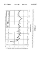
- FIG. 5 is a graph of the electrical power required to maintain a fixed filament length for break up of a jet of fluid over a range of frequencies.
- FIG. 1 illustrates an apparatus 10 for breaking up one or more jets of a high-viscosity fluid, fluids having a viscosity greater than the viscosity of water and typically greater than about 15 cP, into a plurality of monodisperse droplets.
- Apparatus 10 generally includes a housing 20 having a chamber 22, a piston 30 disposed in chamber 22, a magnetic-coil system 40 attached to housing 20 and piston 30, and an oscillator 50 for driving magnetic-coil system 40.
- Housing 20 and piston 30 define a reservoir 12 for receiving a supply of fluid.
- the supply of fluid in reservoir 12 is acted upon by an oscillating motion of piston 30 to impart pressure perturbations on the fluid in reservoir 12 so that the fluid upon discharge from reservoir 12 separates and breaks up into a plurality of monodisperse droplets (as shown in FIG. 3).
- housing 20 includes a vertically extending cylindrical sidewall 24 and a lower horizontally disposed end portion or orifice plate 26 that defines chamber 22 therein.
- Sidewall 24 includes a pair of inlets 28 that extend through sidewall 24 and open into chamber 22 for introduction of fluid into chamber 22.
- End portion 26 of housing 20 includes a plurality of outlets or orifices 25, typically five, (as best shown in FIG. 2) for discharging fluid from reservoir 12.
- Piston 30 comprises a vertically extending sidewall 32 and a lower end portion or piston head 34.
- Vertical sidewall 32 is slidably receivable in chamber 22 of housing 20.
- vertically extending sidewall 32 may be provided with a circumferentially extending groove 23 in which is receivable an O-ring 27 for sealing piston 30 to chamber 22 so as to define reservoir 12.
- Magnetic-coil system 40 includes a permanent magnet 42 and a coil 44 connected to housing 20 and piston 30, respectively.
- coil 42 may be supported around a mounting unit 46, which mounting unit 46 is attached to upper end portion of piston 30.
- Permanent magnet 42 may be supported between coil 44 by magnetic mounting unit 48, which mounting unit 48 is attached to upper portion of housing 20.
- permanent magnet 42 is rigidly linked to orifice plate 26 through mounting unit 48 so that the relative motion therebetween is reduced to maximize the coupling of energy from piston 30 to the fluid.
- a flexible diaphragm 45 may be disposed between mounting unit 46 and mounting unit 48 to seal magnet 42 and coil 44 from chamber 22.
- oscillator 50 for example, an amplified wave generator, provides a time-varying electrical signal of prescribed amplitude and frequency. As described in greater detail below, oscillator 50 and magnetic-coil system 40 combine to drive piston 30 along a longitudinal axis for applying pressure perturbations on fluid in reservoir 12.
- magnet-coil system 40 and oscillator are selectively operable from 10,000 Hz down to DC (e.g., 0 Hz).
- Magnetic-coil system 40 and oscillator 50 typically apply pressure perturbations to the fluid in reservoir 12 having a frequency chosen between about 0 Hz to about 5,000 Hz, and preferably less than about 1,000 Hz, and most preferably between about 100 Hz and 500 Hz.
- high-viscosity fluid to be atomized is directed to the space between housing 20 and piston 30 through inlets 28. The fluid then travels between piston head 34 and orifice plate 24.
- the high-viscosity fluid is desirably supplied to reservoir 12 at a pressure between about 20 psi to about 60 psi.
- Oscillator 50 is activated to produce a current flowing through coil 44, which current interacts with the magnetic field of the permanent magnet 42. This current-magnet interaction produces a force that drives coil 44 and piston 30 along a longitudinal axis of is housing 20.
- oscillator 50 provides an electrical drive signal, for example, a periodic wave based on a single or multiple frequency.
- streams of fluid 14 discharged from apparatus 10 initially comprise a plurality of droplets 16 attached to each other by a filament 18.
- the length required for a stream to completely break up into separate drops is known in the art as the "filament length.”
- Aqueous solutions of carboxymethyl cellulose (CMC) with viscosities up to 2000 cP have been atomized into monodisperse droplets in which the frequency of the sinusoidal excitation was varied over the range 100-3000 Hz which produced droplet diameters from about 1.0 mm to about 5.0 mm.
- apparatus 10 may include a fast-response dynamic pressure transducer 60 mounted in piston head 34 to monitor the performance of apparatus 10 and, in particular, to control the filament length of the jet breakup.
- Control of the filament length is especially important for spray drying and other applications, for example, where the solvent in the jet or droplet stream volatilizes and, therefore, can potentially freeze the fluid jet prior to breakup.
- FIG. 4 illustrates a plot of the peak-to-peak reservoir pressure required for a fixed filament length (480 mm) over a range of frequencies (200 Hz to 3,000 Hz) for a fluid having a fixed viscosity (750 cP).
- the filament length is substantially insensitive to frequency over this range and is essentially a function of the pressure perturbation.
- the filament length can be correlated to the magnitude of the pressure pulse in the reservoir at one frequency and, thus, pressure transducer 60 can act as a "filament length regulator" over a range of frequencies.
- pressure transducer 60 may be coupled to a controller 70 that, in turn, is coupled to oscillator 50, for providing a closed-loop control circuit for the atomization process.
- controller 70 may include a suitable electronic circuit or microprocessor for controlling the power (voltage and current) of the signal to magnetic-coil system 40 to maintain a constant peak-to-peak reservoir pressure during the atomization process, thereby maintaining a fixed filament length.
- the performance of the atomization system can be consistently monitored and adjusted to give a temporally-stable droplet pattern. This can be especially advantageous in systems where the spray distribution is critical (e.g., in gas turbine combustors).
- the present invention also provides a method to minimize the electrical power input required for droplet breakup.
- resonances exist in the reservoir as the fluid between piston head 34 and orifice plate 26 is continually subjected to a time-varying pressure field because of the piston motion.
- the resonances determine the efficiency with which the pressure perturbations are coupled into fluid accelerations and decelerations through orifices 25.
- the resonances are found by operating the atomizer successively over a range of frequencies while maintaining a prescribed pressure perturbation (which as described above also results in a constant filament length) as measured by pressure transducer 60 mounted in head 34 of piston 32. At each frequency, the time-varying voltage and current to the atomizer are measured and the power input calculated.
- FIG. 5 illustrates a plot of the electrical power required to maintain a fixed filament length, (e.g., 480 mm) over a range of frequencies between about 0 Hz to about 3,000 Hz.
- the locations of the minima in the curve define the most efficient operating frequencies for the device (i.e., the minimum power input required for a given filament length). In this test, points of minimum power consumption occurred at frequencies of about 350 Hz, 800 Hz, 1,600 Hz, and 2,500 Hz.
- the size of reservoir 12 may be varied. For example, reducing the gap size (between piston head 34 and orifice plate 26) for a given flow rate, the power required is reduced and the curve shown in FIG. 5 is shifted down. Increasing the gap size, for a given flow rate, the power required is increased and the curve shown in FIG. 5 is shifted up.
- an air or liquid filled bladder 80 and an optical position sensor 90 may be provided for varying the size of reservoir 12.
- optical position sensor 90 is used to accurately regulate bladder 80 to optimize the gap between piston head 34 and orifice plate 26 or the DC position or nominal position of piston 30 about which piston 30 moves or oscillates.
- bladder 80 is disposed between magnet 42 and mounting unit 46. Introducing air or liquid into bladder 80 causes mounting unit 46 to move away from magnet 42, and piston head 34 to move closer to orifice plate 26 to reduce the size of reservoir 12. Removing air from bladder 80 causes mounting unit 46 to move closer to magnet 42, and piston head 34 to move away from orifice plate 26 to increase the size of reservoir 12.
- Optical position sensor 90 for example, a fiber optic sensor, may be fixedly secured to housing 20 and extend through sidewall 32 of piston 30 for indirectly measuring the size of reservoir 12, or the gap between piston head 34 and orifice plate 26.
- the size of bladder 80 may be controlled by controller 70 via a pump or blower (not shown) and an input signal from optical position sensor 90.
- the size of the gap can be coupled with a signal from pressure transducer 60 to optimize the performance of the apparatus.
- the present invention can be coupled with existing atomization systems to enhance the spatial uniformity of the spray.
- existing atomization systems to enhance the spatial uniformity of the spray.
- the additional energy input for the atomization process will tend to reduce the occurrences of voids in the spray pattern.
Abstract
Description
Claims (10)
Priority Applications (4)
| Application Number | Priority Date | Filing Date | Title |
|---|---|---|---|
| US09/197,876 US6135357A (en) | 1998-11-23 | 1998-11-23 | Apparatus for atomizing high-viscosity fluids |
| PCT/US1999/020423 WO2000030762A1 (en) | 1998-11-23 | 1999-09-07 | Apparatus for atomizing high-viscosity fluids using low-frequency vibrations |
| JP2000583636A JP2002530193A (en) | 1998-11-23 | 1999-09-07 | Atomizer for high viscosity fluid using low frequency vibration |
| EP99946765A EP1133364A1 (en) | 1998-11-23 | 1999-09-07 | Apparatus for atomizing high-viscosity fluids using low frequency vibrations |
Applications Claiming Priority (1)
| Application Number | Priority Date | Filing Date | Title |
|---|---|---|---|
| US09/197,876 US6135357A (en) | 1998-11-23 | 1998-11-23 | Apparatus for atomizing high-viscosity fluids |
Publications (1)
| Publication Number | Publication Date |
|---|---|
| US6135357A true US6135357A (en) | 2000-10-24 |
Family
ID=22731101
Family Applications (1)
| Application Number | Title | Priority Date | Filing Date |
|---|---|---|---|
| US09/197,876 Expired - Fee Related US6135357A (en) | 1998-11-23 | 1998-11-23 | Apparatus for atomizing high-viscosity fluids |
Country Status (4)
| Country | Link |
|---|---|
| US (1) | US6135357A (en) |
| EP (1) | EP1133364A1 (en) |
| JP (1) | JP2002530193A (en) |
| WO (1) | WO2000030762A1 (en) |
Cited By (16)
| Publication number | Priority date | Publication date | Assignee | Title |
|---|---|---|---|---|
| US20040059319A1 (en) * | 2002-07-26 | 2004-03-25 | Dornier Medtech Systems Gmbh | System and method for a lithotripter |
| US6772962B2 (en) | 2001-06-09 | 2004-08-10 | Obschestvo s ogranichennoy otvetstvennostyu “Kvarts T-2000” | Low frequency acoustic converter |
| US20050010140A1 (en) * | 2001-11-29 | 2005-01-13 | Dornier Medtech Systems Gmbh | Shockwave or pressure-wave type therapeutic apparatus |
| US20050016285A1 (en) * | 2001-12-19 | 2005-01-27 | Dornier Medtech Systems Gmbh | Testing and monitoring of a shock wave or pressure wave source |
| US20070055157A1 (en) * | 2005-08-05 | 2007-03-08 | Dornier Medtech Systems Gmbh | Shock wave therapy device with image production |
| US20080308971A1 (en) * | 2007-06-18 | 2008-12-18 | Molecular Imprints, Inc. | Solvent-Assisted Layer Formation for Imprint Lithography |
| US20100274378A1 (en) * | 2007-12-21 | 2010-10-28 | Frank Herre | Test method and test apparatus for checking the function of a painting device |
| US20100286574A1 (en) * | 2006-01-17 | 2010-11-11 | Dornier Medtech Systems Gmbh | Treating apparatus |
| US20100305777A1 (en) * | 2008-01-07 | 2010-12-02 | Bio-Rad Laboratories, Inc. | Piston position detection for preparative chromatography column |
| US9060915B2 (en) | 2004-12-15 | 2015-06-23 | Dornier MedTech Systems, GmbH | Methods for improving cell therapy and tissue regeneration in patients with cardiovascular diseases by means of shockwaves |
| US9500170B2 (en) | 2012-10-25 | 2016-11-22 | Picospray, Llc | Fuel injection system |
| US9969930B2 (en) | 2013-08-15 | 2018-05-15 | Halliburton Energy Services, Inc. | Additive fabrication of proppants |
| US10859073B2 (en) | 2016-07-27 | 2020-12-08 | Briggs & Stratton, Llc | Reciprocating pump injector |
| US10947940B2 (en) | 2017-03-28 | 2021-03-16 | Briggs & Stratton, Llc | Fuel delivery system |
| US11002234B2 (en) | 2016-05-12 | 2021-05-11 | Briggs & Stratton, Llc | Fuel delivery injector |
| US11668270B2 (en) | 2018-10-12 | 2023-06-06 | Briggs & Stratton, Llc | Electronic fuel injection module |
Families Citing this family (1)
| Publication number | Priority date | Publication date | Assignee | Title |
|---|---|---|---|---|
| JP5315920B2 (en) * | 2008-10-24 | 2013-10-16 | 株式会社リコー | Toner manufacturing method and manufacturing apparatus |
Citations (11)
| Publication number | Priority date | Publication date | Assignee | Title |
|---|---|---|---|---|
| US3679132A (en) * | 1970-01-21 | 1972-07-25 | Cotton Inc | Jet stream vibratory atomizing device |
| US3868698A (en) * | 1973-10-24 | 1975-02-25 | Mead Corp | Stimulation control apparatus for an ink jet recorder |
| US3900162A (en) * | 1974-01-10 | 1975-08-19 | Ibm | Method and apparatus for generation of multiple uniform fluid filaments |
| EP0033717A1 (en) * | 1980-01-30 | 1981-08-12 | Battelle Development Corporation | Process for breaking a jet into a plurality of droplets of determined size and device for carrying out this process |
| US4327695A (en) * | 1980-12-22 | 1982-05-04 | Ford Motor Company | Unit fuel injector assembly with feedback control |
| EP0235603A2 (en) * | 1986-02-06 | 1987-09-09 | Kanegafuchi Kagaku Kogyo Kabushiki Kaisha | Process for forming uniform liquid droplets |
| US4702418A (en) * | 1985-09-09 | 1987-10-27 | Piezo Electric Products, Inc. | Aerosol dispenser |
| US4930701A (en) * | 1987-09-08 | 1990-06-05 | Mcdonnell Douglas Corporation | Confluent nozzle |
| US5248087A (en) * | 1992-05-08 | 1993-09-28 | Dressler John L | Liquid droplet generator |
| EP0590165A1 (en) * | 1992-09-22 | 1994-04-06 | Schablonentechnik Kufstein Aktiengesellschaft | Electrostatic nozzle, in particular for injecting high-viscosity liquids |
| US5609919A (en) * | 1994-04-21 | 1997-03-11 | Altamat Inc. | Method for producing droplets |
-
1998
- 1998-11-23 US US09/197,876 patent/US6135357A/en not_active Expired - Fee Related
-
1999
- 1999-09-07 WO PCT/US1999/020423 patent/WO2000030762A1/en active Application Filing
- 1999-09-07 EP EP99946765A patent/EP1133364A1/en not_active Withdrawn
- 1999-09-07 JP JP2000583636A patent/JP2002530193A/en active Pending
Patent Citations (11)
| Publication number | Priority date | Publication date | Assignee | Title |
|---|---|---|---|---|
| US3679132A (en) * | 1970-01-21 | 1972-07-25 | Cotton Inc | Jet stream vibratory atomizing device |
| US3868698A (en) * | 1973-10-24 | 1975-02-25 | Mead Corp | Stimulation control apparatus for an ink jet recorder |
| US3900162A (en) * | 1974-01-10 | 1975-08-19 | Ibm | Method and apparatus for generation of multiple uniform fluid filaments |
| EP0033717A1 (en) * | 1980-01-30 | 1981-08-12 | Battelle Development Corporation | Process for breaking a jet into a plurality of droplets of determined size and device for carrying out this process |
| US4327695A (en) * | 1980-12-22 | 1982-05-04 | Ford Motor Company | Unit fuel injector assembly with feedback control |
| US4702418A (en) * | 1985-09-09 | 1987-10-27 | Piezo Electric Products, Inc. | Aerosol dispenser |
| EP0235603A2 (en) * | 1986-02-06 | 1987-09-09 | Kanegafuchi Kagaku Kogyo Kabushiki Kaisha | Process for forming uniform liquid droplets |
| US4930701A (en) * | 1987-09-08 | 1990-06-05 | Mcdonnell Douglas Corporation | Confluent nozzle |
| US5248087A (en) * | 1992-05-08 | 1993-09-28 | Dressler John L | Liquid droplet generator |
| EP0590165A1 (en) * | 1992-09-22 | 1994-04-06 | Schablonentechnik Kufstein Aktiengesellschaft | Electrostatic nozzle, in particular for injecting high-viscosity liquids |
| US5609919A (en) * | 1994-04-21 | 1997-03-11 | Altamat Inc. | Method for producing droplets |
Cited By (23)
| Publication number | Priority date | Publication date | Assignee | Title |
|---|---|---|---|---|
| US6772962B2 (en) | 2001-06-09 | 2004-08-10 | Obschestvo s ogranichennoy otvetstvennostyu “Kvarts T-2000” | Low frequency acoustic converter |
| US20050010140A1 (en) * | 2001-11-29 | 2005-01-13 | Dornier Medtech Systems Gmbh | Shockwave or pressure-wave type therapeutic apparatus |
| US20050016285A1 (en) * | 2001-12-19 | 2005-01-27 | Dornier Medtech Systems Gmbh | Testing and monitoring of a shock wave or pressure wave source |
| US6915697B2 (en) * | 2001-12-19 | 2005-07-12 | Dornier Medtech Systems Gmbh | Testing and monitoring of a shock wave or pressure wave source |
| US7785276B2 (en) | 2002-07-26 | 2010-08-31 | Dornier Medtech Systems Gmbh | System and method for a lithotripter |
| US20040059319A1 (en) * | 2002-07-26 | 2004-03-25 | Dornier Medtech Systems Gmbh | System and method for a lithotripter |
| US9060915B2 (en) | 2004-12-15 | 2015-06-23 | Dornier MedTech Systems, GmbH | Methods for improving cell therapy and tissue regeneration in patients with cardiovascular diseases by means of shockwaves |
| US20070055157A1 (en) * | 2005-08-05 | 2007-03-08 | Dornier Medtech Systems Gmbh | Shock wave therapy device with image production |
| US7988631B2 (en) | 2005-08-05 | 2011-08-02 | Dornier Medtech Systems Gmbh | Shock wave therapy device with image production |
| US20100286574A1 (en) * | 2006-01-17 | 2010-11-11 | Dornier Medtech Systems Gmbh | Treating apparatus |
| US20080308971A1 (en) * | 2007-06-18 | 2008-12-18 | Molecular Imprints, Inc. | Solvent-Assisted Layer Formation for Imprint Lithography |
| US8142702B2 (en) | 2007-06-18 | 2012-03-27 | Molecular Imprints, Inc. | Solvent-assisted layer formation for imprint lithography |
| US20100274378A1 (en) * | 2007-12-21 | 2010-10-28 | Frank Herre | Test method and test apparatus for checking the function of a painting device |
| US8567694B2 (en) * | 2007-12-21 | 2013-10-29 | Durr Sysems GmbH | Test method and test apparatus for checking the function of a painting device |
| US20100305777A1 (en) * | 2008-01-07 | 2010-12-02 | Bio-Rad Laboratories, Inc. | Piston position detection for preparative chromatography column |
| US9500170B2 (en) | 2012-10-25 | 2016-11-22 | Picospray, Llc | Fuel injection system |
| US10330061B2 (en) | 2012-10-25 | 2019-06-25 | Picospray, Llc. | Fuel injection system |
| US11286895B2 (en) | 2012-10-25 | 2022-03-29 | Briggs & Stratton, Llc | Fuel injection system |
| US9969930B2 (en) | 2013-08-15 | 2018-05-15 | Halliburton Energy Services, Inc. | Additive fabrication of proppants |
| US11002234B2 (en) | 2016-05-12 | 2021-05-11 | Briggs & Stratton, Llc | Fuel delivery injector |
| US10859073B2 (en) | 2016-07-27 | 2020-12-08 | Briggs & Stratton, Llc | Reciprocating pump injector |
| US10947940B2 (en) | 2017-03-28 | 2021-03-16 | Briggs & Stratton, Llc | Fuel delivery system |
| US11668270B2 (en) | 2018-10-12 | 2023-06-06 | Briggs & Stratton, Llc | Electronic fuel injection module |
Also Published As
| Publication number | Publication date |
|---|---|
| WO2000030762A1 (en) | 2000-06-02 |
| JP2002530193A (en) | 2002-09-17 |
| EP1133364A1 (en) | 2001-09-19 |
Similar Documents
| Publication | Publication Date | Title |
|---|---|---|
| US6135357A (en) | Apparatus for atomizing high-viscosity fluids | |
| US6315215B1 (en) | Apparatus and method for ultrasonically self-cleaning an orifice | |
| US5145113A (en) | Ultrasonic generation of a submicron aerosol mist | |
| US6629646B1 (en) | Droplet ejector with oscillating tapered aperture | |
| JP3664404B2 (en) | Method for producing droplets | |
| US5409163A (en) | Ultrasonic spray coating system with enhanced spray control | |
| EP0235603A2 (en) | Process for forming uniform liquid droplets | |
| KR101275225B1 (en) | Electrohydrodynamic ink ejecting apparatus | |
| US5687905A (en) | Ultrasound-modulated two-fluid atomization | |
| WO2008076717A1 (en) | Ultrasonic atomization and/or separation system | |
| JPH10502570A (en) | Liquid spray device and method | |
| CA2730242C (en) | Multi-element ultrasonic atomizer | |
| US5173274A (en) | Flash liquid aerosol production method and appartus | |
| JP2004298684A (en) | Liquid drop discharge apparatus and method of manufacturing microcapsule | |
| US5052617A (en) | Atomization of liquids | |
| CN111437897B (en) | Double-flow type monodisperse droplet stream generation method and device | |
| Wang et al. | A new method for producing uniform droplets by continuous-ink-jet technology | |
| Brenn et al. | Drop formation from a vibrating orifice generator driven by modulated electrical signals | |
| Hu et al. | Deformation characteristics of droplet generated by Rayleigh jet breakup | |
| JPH05154425A (en) | Fine droplet formation and device therefor | |
| KR200354871Y1 (en) | Dispersion apparatus for powder comprising nano unit particle | |
| JPH07795A (en) | Method and device for forming uniform and minute droplet group | |
| WO2006047453A2 (en) | Process for high throughput electrohydrodynamic spraying of fluids | |
| GB2388062A (en) | Generating a controlled amount of mist | |
| CN102039409B (en) | Method and equipment for preparing vibrated atomizing gas |
Legal Events
| Date | Code | Title | Description |
|---|---|---|---|
| AS | Assignment |
Owner name: GENERAL ELECTRIC COMPANY, NEW YORK Free format text: ASSIGNMENT OF ASSIGNORS INTEREST;ASSIGNORS:HERRIN, JEFF L.;MOLEZZI, MICHAEL J.;DRESSLER, JOHN L.;REEL/FRAME:009779/0123;SIGNING DATES FROM 19990125 TO 19990209 |
|
| FEPP | Fee payment procedure |
Free format text: PAYOR NUMBER ASSIGNED (ORIGINAL EVENT CODE: ASPN); ENTITY STATUS OF PATENT OWNER: LARGE ENTITY |
|
| FPAY | Fee payment |
Year of fee payment: 4 |
|
| AS | Assignment |
Owner name: JPMORGAN CHASE BANK, N.A. AS ADMINISTRATIVE AGENT, Free format text: SECURITY AGREEMENT;ASSIGNORS:MOMENTIVE PERFORMANCE MATERIALS HOLDINGS INC.;MOMENTIVE PERFORMANCE MATERIALS GMBH & CO. KG;MOMENTIVE PERFORMANCE MATERIALS JAPAN HOLDINGS GK;REEL/FRAME:019511/0166 Effective date: 20070228 |
|
| REMI | Maintenance fee reminder mailed | ||
| LAPS | Lapse for failure to pay maintenance fees | ||
| STCH | Information on status: patent discontinuation |
Free format text: PATENT EXPIRED DUE TO NONPAYMENT OF MAINTENANCE FEES UNDER 37 CFR 1.362 |
|
| FP | Lapsed due to failure to pay maintenance fee |
Effective date: 20081024 |
|
| AS | Assignment |
Owner name: MOMENTIVE PERFORMANCE MATERIALS GMBH & CO KG, GERMANY Free format text: RELEASE BY SECURED PARTY;ASSIGNOR:JPMORGAN CHASE BANK, N.A., AS ADMINISTRATIVE AGENT;REEL/FRAME:054387/0001 Effective date: 20201102 Owner name: MOMENTIVE PERFORMANCE MATERIALS JAPAN HOLDINGS GK, JAPAN Free format text: RELEASE BY SECURED PARTY;ASSIGNOR:JPMORGAN CHASE BANK, N.A., AS ADMINISTRATIVE AGENT;REEL/FRAME:054387/0001 Effective date: 20201102 Owner name: MOMENTIVE PERFORMANCE MATERIALS INC., NEW YORK Free format text: RELEASE BY SECURED PARTY;ASSIGNOR:JPMORGAN CHASE BANK, N.A., AS ADMINISTRATIVE AGENT;REEL/FRAME:054387/0001 Effective date: 20201102 |