US6122133A - Hybrid method of determining a fractional track position of a read transducer in a hard disk drive - Google Patents
Hybrid method of determining a fractional track position of a read transducer in a hard disk drive Download PDFInfo
- Publication number
- US6122133A US6122133A US09/099,485 US9948598A US6122133A US 6122133 A US6122133 A US 6122133A US 9948598 A US9948598 A US 9948598A US 6122133 A US6122133 A US 6122133A
- Authority
- US
- United States
- Prior art keywords
- burst
- fractional
- track position
- servo
- centerline
- Prior art date
- Legal status (The legal status is an assumption and is not a legal conclusion. Google has not performed a legal analysis and makes no representation as to the accuracy of the status listed.)
- Expired - Fee Related
Links
Images


Classifications
-
- G—PHYSICS
- G11—INFORMATION STORAGE
- G11B—INFORMATION STORAGE BASED ON RELATIVE MOVEMENT BETWEEN RECORD CARRIER AND TRANSDUCER
- G11B5/00—Recording by magnetisation or demagnetisation of a record carrier; Reproducing by magnetic means; Record carriers therefor
- G11B5/48—Disposition or mounting of heads or head supports relative to record carriers ; arrangements of heads, e.g. for scanning the record carrier to increase the relative speed
- G11B5/58—Disposition or mounting of heads or head supports relative to record carriers ; arrangements of heads, e.g. for scanning the record carrier to increase the relative speed with provision for moving the head for the purpose of maintaining alignment of the head relative to the record carrier during transducing operation, e.g. to compensate for surface irregularities of the latter or for track following
- G11B5/596—Disposition or mounting of heads or head supports relative to record carriers ; arrangements of heads, e.g. for scanning the record carrier to increase the relative speed with provision for moving the head for the purpose of maintaining alignment of the head relative to the record carrier during transducing operation, e.g. to compensate for surface irregularities of the latter or for track following for track following on disks
- G11B5/59633—Servo formatting
- G11B5/59655—Sector, sample or burst servo format
-
- G—PHYSICS
- G11—INFORMATION STORAGE
- G11B—INFORMATION STORAGE BASED ON RELATIVE MOVEMENT BETWEEN RECORD CARRIER AND TRANSDUCER
- G11B5/00—Recording by magnetisation or demagnetisation of a record carrier; Reproducing by magnetic means; Record carriers therefor
- G11B5/48—Disposition or mounting of heads or head supports relative to record carriers ; arrangements of heads, e.g. for scanning the record carrier to increase the relative speed
- G11B5/58—Disposition or mounting of heads or head supports relative to record carriers ; arrangements of heads, e.g. for scanning the record carrier to increase the relative speed with provision for moving the head for the purpose of maintaining alignment of the head relative to the record carrier during transducing operation, e.g. to compensate for surface irregularities of the latter or for track following
- G11B5/596—Disposition or mounting of heads or head supports relative to record carriers ; arrangements of heads, e.g. for scanning the record carrier to increase the relative speed with provision for moving the head for the purpose of maintaining alignment of the head relative to the record carrier during transducing operation, e.g. to compensate for surface irregularities of the latter or for track following for track following on disks
- G11B5/59605—Circuits
- G11B5/59611—Detection or processing of peak/envelop signals
Definitions
- the invention relates generally to determining a position error signal when jogging a magnetoresistive head in a hard disk drive, and more particularly, to a hybrid approach of determining a fractional track position by using a two-burst algorithm when possible and using a multi-burst algorithm only when necessary.
- FIG. 1 shows a conventional disk drive 10 which has a hard disk assembly (“HDA").
- the HDA includes at least one magnetic disk (“disk”) 12 having a plurality of concentric data tracks, a spindle motor 13 for rapidly rotating the disk 12, and a head stack assembly (“HSA”) 20.
- disk magnetic disk
- HSA head stack assembly
- the HSA 20 includes a transducer head 140 for reading and writing the data onto the magnetic disk 12.
- the typical HSA 20 further includes an actuator assembly 30 and a head gimbal assembly (“HGA") 100.
- the head gimbal assembly (HGA) 100 extends from the actuator assembly 30 and biases the head 140 towards the disk 12.
- the industry presently favors a "rotary" or “swing-type” actuator assembly that move the transducer head 140 in a generally radial manner across the rotating disk 12.
- a servo control system moves the actuator assembly 30 to controllably position the transducer head in order to read or write information from or to particular tracks on the disk 12.
- a flex circuit on the side of the actuator assembly carries read and write signals between a controller 14 and the head 140.
- Each data track includes embedded servo data sectors and user data sectors that are alternately located around the track.
- the servo data comprises track ID fields for identifying data tracks and servo bursts (e.g. A, B) for defining burst pair centerlines.
- the system reads the track ID and samples the servo bursts to generate a position error signal (PES) relative to a desired position.
- PES position error signal
- the servo system uses the magnitude of the PES to move the actuator assembly 30 of the HSA 20 in order to drive the PES toward zero and thereby achieve or maintain the desired position of the transducer head 140.
- the servo control system moves the transducer head 140 toward a desired data track during a "seek" mode based on the track ID field. Once the transducer head 140 is over the desired track, the servo control system enters a "track follow” mode and uses the servo bursts to keep the transducer head at a desired fractional track position relative to a burst pair centerline.
- Older disk drives use an inductive transducer which both reads and writes data onto the disk 12.
- An inductive transducer drive is usually track following directly on a burst pair centerline except, perhaps, when bumped off track or when settling. Even then, an inductive transducer is usually about 80% of the data track pitch in width and is generally uniformly sensitive across its 80% width such that it can operate ⁇ 40% away from the burst pair centerline.
- An inductive head drive therefore, often uses a quadrature pattern of four 100% (of track pitch) servo bursts which provides 50% spacing between two- burst pair centerlines.
- MR heads magnetoresistive heads
- MR heads advantageously support increased a real data density, but suffer from having: (1) an inherent physical separation between the read and write transducers; (2) a smaller average ratio between the width of the read transducer and the data track pitch (about 66% instead of 80%); (3) a relatively wide variance in the width of read transducers about the average (ranging from less than 50% to nearly 100%) which range must often be accommodated due to manufacturing limitations and cost constraints; and (4) a non-linear magnetic response characteristic across the width of the read transducer.
- the separation between the read and write transducers causes them to be variably skewed or radially displaced relative to the burst pair centerlines as they are moved from the inside diameter to the outside diameter of the disk.
- This skew creates a track following problem because positioning is determined by reading the servo bursts with the read transducer even when writing data with the radially displaced write transducer. Because of this skew, the servo control system must read or write while track following away from the burst pair centerline. This process is known as "jogging" and is implemented as a fractional track offset from a servo burst pair centerline.
- the servo system usually jogs when reading but not when writing because a read operation can always be repeated whereas a write error may cause irreversible damage to neighboring data tracks.
- the required jogging offset depends on position for reading, and is always zero for writing.
- the required jogging offset is usually determined from a lookup table.
- the available jogging range is limited by the physical width of the read transducer.
- the magnetoresistive read transducer is relatively narrow, being on average about 66% of a data track pitch wide as compared to 80% for an inductive transducer.
- the maximum jogging range is one half the physical width, such that for a 66% transducer it is ⁇ 33%.
- a particular read transducer may be even narrower than average, being as narrow as 50% of a track pitch or less. In the case of a 50% transducer, the maximum jogging range is ⁇ 25%.
- the read transducer's nonlinear response characteristics may further reduce the available jogging range. Under some circumstances of uncompensated nonlinearity, therefore, it may be possible to jog a 50% read transducer only ⁇ 20% from a given burst pair centerline before it is necessary to commutate to an adjacent burst pair centerline.
- One such servo pattern uses four servo bursts that are 2/3 of a track pitch in width and are arranged in quadrature to provide a 1/3, 1/3, 1/3 pattern of burst pair centerlines.
- a 1/3, 1/3, 1/3 pattern is relatively expensive in terms of manufacturing because each disk drive must spend more time in the servo track writer.
- the invention may be regarded as a method for repeatedly determining a fractional track position of a read transducer in a sampled servo magnetic disk drive for maintaining alignment of the read transducer relative to a centerline of one of a plurality of a concentric data tracks upon a rotating data storage disk, comprising the steps of: reading a plurality of angularly sequential servo bursts that are differently radially spaced with respect to a concentric data track; calculating a first fractional track position using a first algorithm based on a first plurality of the angularly sequential servo bursts; determining whether to retain the first fractional track position; and calculating a second fractional track position using a second algorithm based on a second greater plurality of the servo bursts if the first fractional track position is not retained.
- the invention may be further regarded as a disk drive comprising: a base; a data disk having a plurality of concentric data tracks; a transducer head assembly including a read transducer; a sampled servo control system for moving the transducer head over the data disk relative to the concentric data tracks; a plurality of angularly sequential servo bursts on the data disk comprising four angularly sequential servo bursts A, B, C, D that are each 100% of a track pitch in width and are radially arranged in a 100% quadrature servo pattern wherein two of the servo bursts A, B are equally radially disposed on either side of a "normal" two-burst centerline A/B that is substantially aligned with the centerline of a concentric data track and two of the servo bursts C, D are equally radially disposed on either side of a "quadrature" two-burst centerline C/D that is substantially offset from
- the invention may further be regarded as a method of determining a fraction track position of a read transducer in a disk drive using a repeating pattern of four angularly sequential servo bursts A, B, C, D that are radially arranged in a 100% quadrature servo pattern wherein two of the servo bursts A, B are equally radially disposed on either side of a "normal" two-burst centerline A/B that is substantially aligned with the centerline of a concentric data track and two of the servo bursts C, D are equally radially disposed on either side of a "quadrature" two-burst centerline C/D that is substantially offset from the centerline of the concentric data track by 50% of a track pitch, the method comprising the steps of: reading four servo bursts A, B, C, D for use in calculating a two-burst fractional track position relative to a two-burst centerline and in calculating
- FIG. 1 shows a disk drive that uses the present invention
- FIG. 2 shows the track ID fields and preferred four-burst servo pattern of servo bursts used in the disk drive of FIG. 1 and how this invention divides a repeating portion of the servo pattern into twelve operating zones z0 to z11;
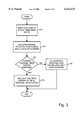
- FIG. 3 is a general flow chart of this invention for use with a servo pattern formed from three or more angularly sequential servo bursts;
- FIG. 4 is a high-level flow chart of a preferred embodiment of this invention for use with the four-burst servo pattern of FIG. 2;
- FIGS. 5A-H (spanning eight pages) is a detailed flow chart of the preferred embodiment.
- FIG. 2 shows a servo burst pattern that was commonly used with relatively wide inductive heads that did not have a jogging requirement.
- the pattern comprises four radially repeating, angularly sequential servo bursts A, B, C, D that are 100% of a track pitch in width and are arranged in quadrature (sometimes hereafter a "100% quadrature pattern").
- the illustrated burst pattern is normally viewed as comprising two alternating pluralities of burst pairs A/B and C/D which respectively define alternating pluralities of "normal” and “quadrature” burst pair centerlines (sometimes hereafter called “two-burst centerlines”).
- the burst pair centerlines are separated by 50% of a track pitch. Accordingly, the 100% quadrature pattern was previously considered impractical for jogging a relatively narrow magnetoresistive read transducer and was largely replaced by the more expensive 1/3, 1/3, 1/3 pattern for that purpose.
- the present invention offers a "hybrid" approach to measuring position that makes it surprisingly practical to use a magnetoresistive read transducer with the 100% quadrature pattern of FIG. 2.
- the present invention reads all four 100% servo bursts and then uniquely selects between a two-burst algorithm and a four-burst algorithm to generate a fractional track position relative to a two-burst centerline or a four-burst centerline.
- the servo system selects between the two-burst and the four-burst algorithms based on the transducer's currently measured position as determined from the relative burst amplitudes of all four servo bursts.
- the present invention preferably uses a two burst algorithm when possible and uses a four-burst algorithm only when necessary.
- This servo system can control a read transducer at various jogging offsets in the context of a relatively inexpensive, quadrature pattern of four 100% servo bursts A, B, C, D, provided that the transducer can read all four bursts. Hence, therefore, the transducer must be at least as wide as 50% of a track pitch so as to physically embrace all four bursts. The inventors have discovered, however, that the system can reasonably control even a sub-50% read transducer that does not physically pass over all four burst because of inherent side-reading characteristics.
- the present invention preferably uses a 100% quadrature pattern of exactly four servo bursts as shown in FIG. 2.
- This invention may theoretically operate with a pattern of three, four, five, or more, angularly sequential servo bursts.
- FIG. 3, in this regard, is a flow chart that offers a broad overview of the present invention with respect to any servo pattern having a multitude of servo bursts wherein "multitude" and "multi” are defined herein to mean three or more bursts.
- the servo system reads the multitude of servo bursts with the read transducer.
- the servo system uses a two-burst algorithm to calculate a potential fractional track position relative to an ordinary two-burst centerline by using less than all of the multitude of servo bursts.
- a two-burst position is generally best if the transducer is near the two-burst centerline and therefore, reads approximately equal portions of the two bursts.
- the fractional track offset determined with the two-burst algorithm is only "potential", however, because it may be supplanted by a fractional track position determined relative to an adjacent multi-burst centerline defined by a multi-burst algorithm and using a multitude of bursts.
- the servo system applies a "retention criteria" to determine if the fractional track position developed with the two-burst algorithm will be accepted or replaced. If yes, at step 104, the potential fractional track position becomes the final fractional track position. If no, at step 105, the servo system uses a multi-burst algorithm to calculate a final fractional track position.
- FIG. 4 is a flow chart that offers a broad overview of a presently preferred embodiment of the invention designed specifically for the 100% quadrature pattern of FIG. 2.
- the subject pattern has four bursts.
- the servo system reads all four 100% servo bursts A, B, C, and D.
- the servo system uses a two-burst algorithm to calculate a potential fractional track position relative to an ordinary two-burst centerline.
- the two-burst algorithm provides a potential fractional track position relative to a "normal" A/B centerline or a "quadrature" C/D centerline, whichever is nearer.
- FIG. 2 shows how this invention defines a plurality of two-burst centerlines and four-burst centerlines and how this invention divides a repeating portion of the servo pattern into twelve zones z0 to z11 for use in preferentially selecting a two-burst centerline and alternatively selecting a four-burst centerline for determining the fractional track position of the read transducer.
- the preferred servo system divides the available transducer positions into twelve repeating "zones" z0 to z11 having position ranges that are represented by appropriately numbered arrows.
- the zones are illustrated in "upper” and “lower” rows based on their two-burst versus four-burst characteristic.
- the upper zones z0, z1, z3, z4, z6, z7, z9, and z10 represent positions that are near the conventional two-burst centerlines where, ideally, the read transducer is controlled with a two-burst algorithm.
- the lower zones z2, z5, z8, and z11 represent positions that are between the conventional two-burst centerlines, near the four-burst centerlines provided by this invention, where the read transducer, if necessary, is controlled by a four-burst algorithm.
- the zones could theoretically have abrupt boundaries.
- each two-burst zone z0, z1, z3, z4, z6, z7, z9, and z10 preferably overlaps an adjacent one of the four-burst zones z2, z5, z8, or z11 so that the "limit" in steps 203 of FIG. 4 may be dynamically shifted to provide some hysteresis that prevents the system from jumping back and forth between algorithms when the transducer is operating at the interface between a two-burst zone and a four-burst zone.
- FIG. 5 implemented over eight pages as FIGS. 5A-5H, is a detailed flow chart showing the operation of the preferred servo system which uses a four burst, 100% quadrature pattern that is divided into twelve zones z0 to z11 as shown in FIG. 2.
- Steps 301 to 303 relate to varying the "limit" in order to provide hysteresis as first discussed above with respect to step 203 in the general flow chart of FIG. 4.
- the limit is always measured relative to a nearby two-burst centerline.
- the servo system determines whether the fractional track position from the previous servo sample was derived with a four-burst algorithm (N-Q or N+Q), or a two-burst algorithm (A-B or C-D).
- a limit value LIMZONE is set to a relatively large value at step 302 (around 16% of a track pitch) in order to broaden the two-burst zone and thereby make it more likely that the system will again use a use a two-burst algorithm on this servo sample.
- LIMZONE is set to a relatively small value at step 303 (around 10% of a track pitch) in order to broaden the four-burst zone and thereby make it more likely that the system will use a use a four-burst algorithm once again on this servo sample.
- the limit value LIMZONE is used in decision steps 541, 551, 641, 651, 741, 751, 841, and 851 discussed below.
- the servo system reads all four 100% servo bursts A, B, C, and D and stores the values in appropriate registers.
- the system has a tentative track ID CYLNEW (not explicitly shown in FIG. 5 but note the track ID field at the top of FIG. 2), but it assumes that the read transducer could be in any one of the twelve zones z0 to z11 shown in FIG. 2.
- the system now makes several successive comparisons to eliminate candidate zones and ultimately determine the occupied zone.
- the system determines whether or not the new cylinder CYLNEW that was tentatively identified only by the track ID field is odd or even and either does nothing or corrects CYLNEW. It is desirable to correct the new cylinder CYLNEW by ⁇ 1 unit because the track ID may be ambiguous by one bit since the transducer often passes over part of two adjacent track ID fields and such fields are customarily encoded with a gray code that varies by one bit from cylinder to cylinder.
- Step 305 the system knows whether the track ID should be odd or even based on whether the transducer passed over an "odd” C bursts or an "even” D burst. If CYLNEW is odd or even as expected in Steps 530, 630, 730, or 830, as the case may be, then the system skips to steps 532, 632, 732, or 832, respectively, without changing CYLNEW.
- CYLNEW is the opposite of what is expected in expected in Steps 530, 630, 730, or 830, however, the system proceeds to steps 531, 631, 731, or 831, respectively, and either increments or decrements CYLNEW to change it from odd to even, or vice versa.
- the system knows whether to increment or decrement from having passed through one of the previous steps 320 or 420 which respectively indicated whether the transducer was to the inside or outside of an even C burst or to the inside or outside of an odd D burst.
- step 531 the system knows that the transducer passed over an "odd" C burst associated with cylinder #1, or #3, and so on, and that the transducer passed over the outside (right) half of the C burst and, therefore, closer to a lower numbered even cylinder than to a higher numbered even cylinder. Accordingly, if CYLNEW is erroneously even, the system makes CYLNEW odd by adding one unit rather than subtracting one unit. Steps 631, 731, and 831 operate in a similar manner and need not be described further.
- the servo system compares the relative magnitude of servo bursts C and A, B and C, A and D, and D and B to further narrow the list of candidate zones from three to only two, a four-burst zone and a two-burst zone. In essence, the servo system determines whether the transducer is to the inside (left) or outside (right) of the four-burst centerlines associated with zones z5, z8, z2, and z11, respectively. In step 532, for example, the servo system compares the relative magnitude of servo bursts C and A.
- the system uses a two-burst algorithm to derive a potential fractional track position POTEN -- FRACTION relative to one of the two-burst centerlines A/B or C/D.
- the system uses an algorithm based on A-B if the transducer is closer to an A/B centerline and an algorithm based on C-D if it is closer to a C/D centerline.
- the system knows the transducer is in the inside (left) half of zone z5 or in zone z6 such that it is closer to the A/B centerline.
- the system assumes the read transducer is now in the two-burst zone z6 and applies the following two-burst formula involving A-B to derive the potential fractional track position: ##EQU1##
- the burst normalization value BRST -- NORM -- AB is a calibration factor relating to ensuring that the system reads zero "counts" when the transducer is not over a burst and full scale (256 "counts” in the preferred system) when the transducer is completely over a burst.
- the negative sign is representative of the fact that the A burst is to the outside (right) of the B burst for odd tracks (as here) and to the inside (left) of the B burst on even tracks.
- Steps 550, 640 or 650, 740 or 750, and 840 or 850 derive a potential fractional track position in a similar fashion and will not be described for the sake of brevity.
- Step 540 The ⁇ brackets ⁇ in the flowchart of FIG. 5, e.g. ##EQU2## in Step 540, are included to suggest that the quotient values may be adjusted from their nominal values to compensate for magnetic nonlinearities across the width of the read transducer.
- linearization parameters or table values are generally determined during a manufacturing phase known as "Intelligent Burn-In” (IBI).
- IBI Intelligent Burn-In
- One possible linearization method is disclosed in prior commonly assigned application Ser. No. 08/893,815 that was filed by Nazarian et al. on Jul. 11, 1997, entitled “Self-PES Linearity Calibration Method,” and is fully incorporated herein by reference.
- the quotient values may also be adjusted to provide any offset needed to adjust the fractional track position so that the two-burst centerlines A/B and C/D appear to be 50% of a track pitch away from each other.
- the system compares the absolute value of the potential fractional track position POTEN -- FRACTION with the limit value LIMZONE set relatively narrow or relatively wide at the start of this process in steps 301 to 303 so that the system tends to choose the same type of zone as was chosen in the last sample.
- the system makes this comparison in order to select between the final two candidates, a four-burst zone and an adjacent two burst zone.
- the candidates are zones z6 and z5, and starting from step 551 the two candidates are zones z5 and z4. Note that the intermediate four-burst zone z5 is a candidate in both cases.
- step 541 If the absolute value of the potential fractional track position POTEN -- FRACTION is less than the limit value LIMZONE in step 541, the servo system proceeds to step 561 and selects the two-burst zone z6. If, on the other hand, the absolute value of the potential fractional track position POTEN -- FRACTION is greater than the limit value LIMZONE in step 541, the servo system proceeds to step 562 and selects the four-burst zone z5. Similarly speaking, starting from step 551, the system proceeds to step 562 and selects the four-burst zone z5 or to step 563 and selects the two-burst zone z4.
- Steps 641, 651, 661, 662, and 663 operate in a similar fashion to select between zones z9 and z8 or z8 and z7.
- Steps 741, 751, 761, 762, and 763 operate in a similar fashion to select between zones z3 and z2 or z2 and z1.
- steps 841, 851, 861, 862, and 863 operate in a similar fashion to select between zones z0 and z11 or z11 and z10.
- steps 570, 670, 770, and 870 i.e. if the system "rejected" a two-burst algorithm and determined that the transducer is better viewed as being in one of the four-burst zones z5, z8, z2 or z11, respectively, the system uses a four-burst algorithm to derive a "final" fractional track position POTEN -- FRACTION relative to a four-burst centerline N-Q or N+Q that bisects the subject four-burst zone.
- the burst normalization value BRST -- NORM -- NQ is again a calibration factor and the negative sign is again representative of the fact that N-Q has opposite polarities for odd and even tracks (as does N+Q).
- the "-64" adjustment accounts for the fact that the four-burst centerline N-Q which bisects the four-burst zone z5 is 25% of a track pitch (64 "counts") to the outside (right) of the two-burst A/B centerline.
- Steps 670, 770, and 870 use a four-burst algorithm to derive a "final" fractional track position in a similar fashion and, as with other such steps, will not be described for the sake of brevity.
- the system preferably implements a linearization process like that discussed above to compensate for magnetic nonlinearities across the width of the read transducer and, in this case, to provide any needed offset to adjust the fractional track position and make the N-Q and N+Q centerlines appear to be 25% of a track pitch away from the two-burst centerlines A/B and C/D.
- step 350 the system calculates the overall position error signal PES as the sum of the integer track error and the fractional track error where the former is defined as the difference between the current cylinder and the desired cylinder (track), 256 ⁇ (CYLNEW-CYLDES) in terms of “counts”, and where the latter is based on the current fractional track position and the desired fractional track jogging offset (if any), (POTEN -- FRACTION-OFSTTK) in terms of "counts.”
- the demanded fractional track jogging offset OFFSTK is always zero for writing and varies only for reading.
- the preferred two burst algorithms are based on an A-B formula and a C-D formula.
- the preferred system substantially implements the two-burst algorithms as (A-B)/(A+B) when the read transducer is near a "normal" two-burst centerline A/B, and as (C-D)/(C+D) when the transducer head is near a "quadrature" two-burst centerline C/D.
- These algorithms require a divide for self-normalization, but do not require automatic gain control (AGC).
- AGC automatic gain control
- the system could use K(A-B) and K(C-D) where K is an AGC scaling factor that is updated at the start of each servo sample with a leading AGC field.
- the preferred implementation of the four-burst algorithms requires the same number of divides as the two-burst versions--one.
- the preferred four-burst algorithms are substantially implemented as ##EQU5##
Abstract
Description
Claims (31)
Priority Applications (1)
| Application Number | Priority Date | Filing Date | Title |
|---|---|---|---|
| US09/099,485 US6122133A (en) | 1998-06-17 | 1998-06-17 | Hybrid method of determining a fractional track position of a read transducer in a hard disk drive |
Applications Claiming Priority (1)
| Application Number | Priority Date | Filing Date | Title |
|---|---|---|---|
| US09/099,485 US6122133A (en) | 1998-06-17 | 1998-06-17 | Hybrid method of determining a fractional track position of a read transducer in a hard disk drive |
Publications (1)
| Publication Number | Publication Date |
|---|---|
| US6122133A true US6122133A (en) | 2000-09-19 |
Family
ID=22275236
Family Applications (1)
| Application Number | Title | Priority Date | Filing Date |
|---|---|---|---|
| US09/099,485 Expired - Fee Related US6122133A (en) | 1998-06-17 | 1998-06-17 | Hybrid method of determining a fractional track position of a read transducer in a hard disk drive |
Country Status (1)
| Country | Link |
|---|---|
| US (1) | US6122133A (en) |
Cited By (112)
| Publication number | Priority date | Publication date | Assignee | Title |
|---|---|---|---|---|
| US20030197968A1 (en) * | 2002-04-18 | 2003-10-23 | Sacks Alexei Hiram | Bi-directional servo track writing to minimize sidewall writing at high skew angles |
| US6671790B2 (en) | 2001-06-04 | 2003-12-30 | Seagate Technology Llc | Optimizing reader to writer offset compensation for a disc drive |
| WO2005015552A2 (en) * | 2003-08-06 | 2005-02-17 | Mempile Inc. | Methods and apparatus for formatting and tracking information in a three-dimensional storage medium |
| US20050052777A1 (en) * | 2003-09-03 | 2005-03-10 | Kabushiki Kaisha Toshiba | Method and apparatus for positioning head using servo burst signals in a disk drive |
| US20050248866A1 (en) * | 2001-09-06 | 2005-11-10 | Fujitsu Limited | Magnetic pattern transferring method for performing magnetic pattern transfer while correcting a magneticallly different part |
| US20070053098A1 (en) * | 2005-08-24 | 2007-03-08 | Seagate Technology Llc | Controller with fractional position algorithm |
| US20080002277A1 (en) * | 2002-04-18 | 2008-01-03 | Seagate Technology Llc | Bi-directional servo track writing to minimize sidewall writing at high skew angles |
| US20080219130A1 (en) * | 2003-08-14 | 2008-09-11 | Mempile Inc. C/O Phs Corporate Services, Inc. | Methods and Apparatus for Formatting and Tracking Information for Three-Dimensional Storage Medium |
| US8116026B2 (en) * | 2004-02-10 | 2012-02-14 | Marvell International Ltd. | Method and system for head position control in embedded disk drive controllers |
| US8824081B1 (en) | 2012-03-13 | 2014-09-02 | Western Digital Technologies, Inc. | Disk drive employing radially coherent reference pattern for servo burst demodulation and fly height measurement |
| US8830617B1 (en) | 2013-05-30 | 2014-09-09 | Western Digital Technologies, Inc. | Disk drive adjusting state estimator to compensate for unreliable servo data |
| US8879191B1 (en) | 2012-11-14 | 2014-11-04 | Western Digital Technologies, Inc. | Disk drive modifying rotational position optimization algorithm to achieve target performance for limited stroke |
| US8891194B1 (en) | 2013-05-14 | 2014-11-18 | Western Digital Technologies, Inc. | Disk drive iteratively adapting correction value that compensates for non-linearity of head |
| US8891191B1 (en) | 2014-05-06 | 2014-11-18 | Western Digital Technologies, Inc. | Data storage device initializing read signal gain to detect servo seed pattern |
| US8896957B1 (en) | 2013-05-10 | 2014-11-25 | Western Digital Technologies, Inc. | Disk drive performing spiral scan of disk surface to detect residual data |
| US8902538B1 (en) | 2013-03-29 | 2014-12-02 | Western Digital Technologies, Inc. | Disk drive detecting crack in microactuator |
| US8902539B1 (en) | 2014-05-13 | 2014-12-02 | Western Digital Technologies, Inc. | Data storage device reducing seek power consumption |
| US8913342B1 (en) | 2014-03-21 | 2014-12-16 | Western Digital Technologies, Inc. | Data storage device adjusting range of microactuator digital-to-analog converter based on operating temperature |
| US8917474B1 (en) | 2011-08-08 | 2014-12-23 | Western Digital Technologies, Inc. | Disk drive calibrating a velocity profile prior to writing a spiral track |
| US8917475B1 (en) | 2013-12-20 | 2014-12-23 | Western Digital Technologies, Inc. | Disk drive generating a disk locked clock using radial dependent timing feed-forward compensation |
| US8922931B1 (en) | 2013-05-13 | 2014-12-30 | Western Digital Technologies, Inc. | Disk drive releasing variable amount of buffered write data based on sliding window of predicted servo quality |
| US8922937B1 (en) | 2012-04-19 | 2014-12-30 | Western Digital Technologies, Inc. | Disk drive evaluating multiple vibration sensor outputs to enable write-protection |
| US8922940B1 (en) | 2014-05-27 | 2014-12-30 | Western Digital Technologies, Inc. | Data storage device reducing spindle motor voltage boost during power failure |
| US8922938B1 (en) | 2012-11-02 | 2014-12-30 | Western Digital Technologies, Inc. | Disk drive filtering disturbance signal and error signal for adaptive feed-forward compensation |
| US8929022B1 (en) | 2012-12-19 | 2015-01-06 | Western Digital Technologies, Inc. | Disk drive detecting microactuator degradation by evaluating frequency component of servo signal |
| US8929021B1 (en) | 2012-03-27 | 2015-01-06 | Western Digital Technologies, Inc. | Disk drive servo writing from spiral tracks using radial dependent timing feed-forward compensation |
| US8934186B1 (en) | 2014-03-26 | 2015-01-13 | Western Digital Technologies, Inc. | Data storage device estimating servo zone to reduce size of track address |
| US8937784B1 (en) | 2012-08-01 | 2015-01-20 | Western Digital Technologies, Inc. | Disk drive employing feed-forward compensation and phase shift compensation during seek settling |
| US8941945B1 (en) | 2014-06-06 | 2015-01-27 | Western Digital Technologies, Inc. | Data storage device servoing heads based on virtual servo tracks |
| US8941939B1 (en) | 2013-10-24 | 2015-01-27 | Western Digital Technologies, Inc. | Disk drive using VCM BEMF feed-forward compensation to write servo data to a disk |
| US8947819B1 (en) | 2012-08-28 | 2015-02-03 | Western Digital Technologies, Inc. | Disk drive implementing hysteresis for primary shock detector based on a more sensitive secondary shock detector |
| US8953278B1 (en) | 2011-11-16 | 2015-02-10 | Western Digital Technologies, Inc. | Disk drive selecting disturbance signal for feed-forward compensation |
| US8953271B1 (en) | 2013-05-13 | 2015-02-10 | Western Digital Technologies, Inc. | Disk drive compensating for repeatable run out selectively per zone |
| US8958169B1 (en) | 2014-06-11 | 2015-02-17 | Western Digital Technologies, Inc. | Data storage device re-qualifying state estimator while decelerating head |
| US8970979B1 (en) | 2013-12-18 | 2015-03-03 | Western Digital Technologies, Inc. | Disk drive determining frequency response of actuator near servo sample frequency |
| US8982490B1 (en) | 2014-04-24 | 2015-03-17 | Western Digital Technologies, Inc. | Data storage device reading first spiral track while simultaneously writing second spiral track |
| US8982501B1 (en) | 2014-09-22 | 2015-03-17 | Western Digital Technologies, Inc. | Data storage device compensating for repeatable disturbance when commutating a spindle motor |
| US8995075B1 (en) | 2012-06-21 | 2015-03-31 | Western Digital Technologies, Inc. | Disk drive adjusting estimated servo state to compensate for transient when crossing a servo zone boundary |
| US8995082B1 (en) | 2011-06-03 | 2015-03-31 | Western Digital Technologies, Inc. | Reducing acoustic noise in a disk drive when exiting idle mode |
| US9001454B1 (en) | 2013-04-12 | 2015-04-07 | Western Digital Technologies, Inc. | Disk drive adjusting phase of adaptive feed-forward controller when reconfiguring servo loop |
| US9007714B1 (en) | 2014-07-18 | 2015-04-14 | Western Digital Technologies Inc. | Data storage device comprising slew rate anti-windup compensation for microactuator |
| US9013825B1 (en) | 2014-03-24 | 2015-04-21 | Western Digital Technologies, Inc. | Electronic system with vibration management mechanism and method of operation thereof |
| US9013824B1 (en) | 2014-06-04 | 2015-04-21 | Western Digital Technologies, Inc. | Data storage device comprising dual read sensors and dual servo channels to improve servo demodulation |
| US9025269B1 (en) | 2014-01-02 | 2015-05-05 | Western Digital Technologies, Inc. | Disk drive compensating for cycle slip of disk locked clock when reading mini-wedge |
| US9026728B1 (en) | 2013-06-06 | 2015-05-05 | Western Digital Technologies, Inc. | Disk drive applying feed-forward compensation when writing consecutive data tracks |
| US9047901B1 (en) | 2013-05-28 | 2015-06-02 | Western Digital Technologies, Inc. | Disk drive measuring spiral track error by measuring a slope of a spiral track across a disk radius |
| US9047919B1 (en) | 2013-03-12 | 2015-06-02 | Western Digitial Technologies, Inc. | Disk drive initializing servo read channel by reading data preceding servo preamble during access operation |
| US9047932B1 (en) | 2014-03-21 | 2015-06-02 | Western Digital Technologies, Inc. | Data storage device adjusting a power loss threshold based on samples of supply voltage |
| US9053712B1 (en) | 2014-05-07 | 2015-06-09 | Western Digital Technologies, Inc. | Data storage device reading servo sector while writing data sector |
| US9053726B1 (en) | 2014-01-29 | 2015-06-09 | Western Digital Technologies, Inc. | Data storage device on-line adapting disturbance observer filter |
| US9053727B1 (en) | 2014-06-02 | 2015-06-09 | Western Digital Technologies, Inc. | Disk drive opening spiral crossing window based on DC and AC spiral track error |
| US9058826B1 (en) | 2014-02-13 | 2015-06-16 | Western Digital Technologies, Inc. | Data storage device detecting free fall condition from disk speed variations |
| US9058834B1 (en) | 2013-11-08 | 2015-06-16 | Western Digital Technologies, Inc. | Power architecture for low power modes in storage devices |
| US9058827B1 (en) | 2013-06-25 | 2015-06-16 | Western Digitial Technologies, Inc. | Disk drive optimizing filters based on sensor signal and disturbance signal for adaptive feed-forward compensation |
| US9064537B1 (en) | 2013-09-13 | 2015-06-23 | Western Digital Technologies, Inc. | Disk drive measuring radial offset between heads by detecting a difference between ramp contact |
| US9070411B1 (en) | 2013-07-04 | 2015-06-30 | Seagate Technology Llc | Writable servo overlap zones |
| US9076472B1 (en) | 2014-08-21 | 2015-07-07 | Western Digital (Fremont), Llc | Apparatus enabling writing servo data when disk reaches target rotation speed |
| US9076471B1 (en) | 2013-07-31 | 2015-07-07 | Western Digital Technologies, Inc. | Fall detection scheme using FFS |
| US9076473B1 (en) | 2014-08-12 | 2015-07-07 | Western Digital Technologies, Inc. | Data storage device detecting fly height instability of head during load operation based on microactuator response |
| US9076490B1 (en) | 2012-12-12 | 2015-07-07 | Western Digital Technologies, Inc. | Disk drive writing radial offset spiral servo tracks by reading spiral seed tracks |
| US9093105B2 (en) | 2011-12-09 | 2015-07-28 | Western Digital Technologies, Inc. | Disk drive charging capacitor using motor supply voltage during power failure |
| US9099147B1 (en) | 2014-09-22 | 2015-08-04 | Western Digital Technologies, Inc. | Data storage device commutating a spindle motor using closed-loop rotation phase alignment |
| US9111575B1 (en) | 2014-10-23 | 2015-08-18 | Western Digital Technologies, Inc. | Data storage device employing adaptive feed-forward control in timing loop to compensate for vibration |
| US9129630B1 (en) | 2014-12-16 | 2015-09-08 | Western Digital Technologies, Inc. | Data storage device employing full servo sectors on first disk surface and mini servo sectors on second disk surface |
| US9142225B1 (en) | 2014-03-21 | 2015-09-22 | Western Digital Technologies, Inc. | Electronic system with actuator control mechanism and method of operation thereof |
| US9142235B1 (en) | 2009-10-27 | 2015-09-22 | Western Digital Technologies, Inc. | Disk drive characterizing microactuator by injecting sinusoidal disturbance and evaluating feed-forward compensation values |
| US9141177B1 (en) | 2014-03-21 | 2015-09-22 | Western Digital Technologies, Inc. | Data storage device employing glitch compensation for power loss detection |
| US9142249B1 (en) | 2013-12-06 | 2015-09-22 | Western Digital Technologies, Inc. | Disk drive using timing loop control signal for vibration compensation in servo loop |
| US9147418B1 (en) | 2013-06-20 | 2015-09-29 | Western Digital Technologies, Inc. | Disk drive compensating for microactuator gain variations |
| US9147428B1 (en) | 2013-04-24 | 2015-09-29 | Western Digital Technologies, Inc. | Disk drive with improved spin-up control |
| US9153283B1 (en) | 2014-09-30 | 2015-10-06 | Western Digital Technologies, Inc. | Data storage device compensating for hysteretic response of microactuator |
| US9165583B1 (en) | 2014-10-29 | 2015-10-20 | Western Digital Technologies, Inc. | Data storage device adjusting seek profile based on seek length when ending track is near ramp |
| US9171568B1 (en) | 2014-06-25 | 2015-10-27 | Western Digital Technologies, Inc. | Data storage device periodically re-initializing spindle motor commutation sequence based on timing data |
| US9171567B1 (en) | 2014-05-27 | 2015-10-27 | Western Digital Technologies, Inc. | Data storage device employing sliding mode control of spindle motor |
| US9208808B1 (en) | 2014-04-22 | 2015-12-08 | Western Digital Technologies, Inc. | Electronic system with unload management mechanism and method of operation thereof |
| US9208815B1 (en) | 2014-10-09 | 2015-12-08 | Western Digital Technologies, Inc. | Data storage device dynamically reducing coast velocity during seek to reduce power consumption |
| US9208810B1 (en) | 2014-04-24 | 2015-12-08 | Western Digital Technologies, Inc. | Data storage device attenuating interference from first spiral track when reading second spiral track |
| US9214175B1 (en) | 2015-03-16 | 2015-12-15 | Western Digital Technologies, Inc. | Data storage device configuring a gain of a servo control system for actuating a head over a disk |
| US9230592B1 (en) | 2014-12-23 | 2016-01-05 | Western Digital Technologies, Inc. | Electronic system with a method of motor spindle bandwidth estimation and calibration thereof |
| US9230593B1 (en) | 2014-12-23 | 2016-01-05 | Western Digital Technologies, Inc. | Data storage device optimizing spindle motor power when transitioning into a power failure mode |
| US9245560B1 (en) | 2015-03-09 | 2016-01-26 | Western Digital Technologies, Inc. | Data storage device measuring reader/writer offset by reading spiral track and concentric servo sectors |
| US9245540B1 (en) | 2014-10-29 | 2016-01-26 | Western Digital Technologies, Inc. | Voice coil motor temperature sensing circuit to reduce catastrophic failure due to voice coil motor coil shorting to ground |
| US9245577B1 (en) | 2015-03-26 | 2016-01-26 | Western Digital Technologies, Inc. | Data storage device comprising spindle motor current sensing with supply voltage noise attenuation |
| US9251823B1 (en) | 2014-12-10 | 2016-02-02 | Western Digital Technologies, Inc. | Data storage device delaying seek operation to avoid thermal asperities |
| US9269386B1 (en) | 2014-01-29 | 2016-02-23 | Western Digital Technologies, Inc. | Data storage device on-line adapting disturbance observer filter |
| US9286927B1 (en) | 2014-12-16 | 2016-03-15 | Western Digital Technologies, Inc. | Data storage device demodulating servo burst by computing slope of intermediate integration points |
| US9286925B1 (en) | 2015-03-26 | 2016-03-15 | Western Digital Technologies, Inc. | Data storage device writing multiple burst correction values at the same radial location |
| US9343102B1 (en) | 2015-03-25 | 2016-05-17 | Western Digital Technologies, Inc. | Data storage device employing a phase offset to generate power from a spindle motor during a power failure |
| US9343094B1 (en) | 2015-03-26 | 2016-05-17 | Western Digital Technologies, Inc. | Data storage device filtering burst correction values before downsampling the burst correction values |
| US9350278B1 (en) | 2014-06-13 | 2016-05-24 | Western Digital Technologies, Inc. | Circuit technique to integrate voice coil motor support elements |
| US9349401B1 (en) | 2014-07-24 | 2016-05-24 | Western Digital Technologies, Inc. | Electronic system with media scan mechanism and method of operation thereof |
| US9355667B1 (en) | 2014-11-11 | 2016-05-31 | Western Digital Technologies, Inc. | Data storage device saving absolute position at each servo wedge for previous write operations |
| US9355676B1 (en) | 2015-03-25 | 2016-05-31 | Western Digital Technologies, Inc. | Data storage device controlling amplitude and phase of driving voltage to generate power from a spindle motor |
| US9361939B1 (en) | 2014-03-10 | 2016-06-07 | Western Digital Technologies, Inc. | Data storage device characterizing geometry of magnetic transitions |
| US9396751B1 (en) | 2015-06-26 | 2016-07-19 | Western Digital Technologies, Inc. | Data storage device compensating for fabrication tolerances when measuring spindle motor current |
| US9407015B1 (en) | 2014-12-29 | 2016-08-02 | Western Digital Technologies, Inc. | Automatic power disconnect device |
| US9418689B2 (en) | 2014-10-09 | 2016-08-16 | Western Digital Technologies, Inc. | Data storage device generating an operating seek time profile as a function of a base seek time profile |
| US9424868B1 (en) | 2015-05-12 | 2016-08-23 | Western Digital Technologies, Inc. | Data storage device employing spindle motor driving profile during seek to improve power performance |
| US9424871B1 (en) | 2012-09-13 | 2016-08-23 | Western Digital Technologies, Inc. | Disk drive correcting an error in a detected gray code |
| US9437237B1 (en) | 2015-02-20 | 2016-09-06 | Western Digital Technologies, Inc. | Method to detect power loss through data storage device spindle speed |
| US9437231B1 (en) | 2015-09-25 | 2016-09-06 | Western Digital Technologies, Inc. | Data storage device concurrently controlling and sensing a secondary actuator for actuating a head over a disk |
| US9454212B1 (en) | 2014-12-08 | 2016-09-27 | Western Digital Technologies, Inc. | Wakeup detector |
| US9471072B1 (en) | 2013-11-14 | 2016-10-18 | Western Digital Technologies, Inc | Self-adaptive voltage scaling |
| US9484733B1 (en) | 2013-09-11 | 2016-11-01 | Western Digital Technologies, Inc. | Power control module for data storage device |
| US9542966B1 (en) | 2015-07-09 | 2017-01-10 | Western Digital Technologies, Inc. | Data storage devices and methods with frequency-shaped sliding mode control |
| US9564162B1 (en) | 2015-12-28 | 2017-02-07 | Western Digital Technologies, Inc. | Data storage device measuring resonant frequency of a shock sensor by applying differential excitation and measuring oscillation |
| US9581978B1 (en) | 2014-12-17 | 2017-02-28 | Western Digital Technologies, Inc. | Electronic system with servo management mechanism and method of operation thereof |
| US9620160B1 (en) | 2015-12-28 | 2017-04-11 | Western Digital Technologies, Inc. | Data storage device measuring resonant frequency of a shock sensor by inserting the shock sensor into an oscillator circuit |
| US9823294B1 (en) | 2013-10-29 | 2017-11-21 | Western Digital Technologies, Inc. | Negative voltage testing methodology and tester |
| US9886285B2 (en) | 2015-03-31 | 2018-02-06 | Western Digital Technologies, Inc. | Communication interface initialization |
| US9899834B1 (en) | 2015-11-18 | 2018-02-20 | Western Digital Technologies, Inc. | Power control module using protection circuit for regulating backup voltage to power load during power fault |
| US9959204B1 (en) | 2015-03-09 | 2018-05-01 | Western Digital Technologies, Inc. | Tracking sequential ranges of non-ordered data |
Citations (6)
| Publication number | Priority date | Publication date | Assignee | Title |
|---|---|---|---|---|
| US5381281A (en) * | 1989-07-27 | 1995-01-10 | Conner Peripherals, Inc. | Disk drive system using multiple embedded quadrature servo fields |
| US5602693A (en) * | 1994-12-14 | 1997-02-11 | Micropolis (S) Pte Ltd. | Method and apparatus for sensing position in a disk drive |
| US5771131A (en) * | 1996-07-18 | 1998-06-23 | Quantum Corporation | Tracking in hard disk drive using magnetoresistive heads |
| US5781361A (en) * | 1996-05-01 | 1998-07-14 | Samsung Electronics, Ltd. | Method and apparatus for generating servo information |
| US5825579A (en) * | 1996-04-04 | 1998-10-20 | International Business Machines Corporation | Disk drive servo sensing gain normalization and linearization |
| US6002541A (en) * | 1997-06-30 | 1999-12-14 | International Business Machines Corporation | Method and apparatus for providing a linear position error sensing (PES) signal |
-
1998
- 1998-06-17 US US09/099,485 patent/US6122133A/en not_active Expired - Fee Related
Patent Citations (6)
| Publication number | Priority date | Publication date | Assignee | Title |
|---|---|---|---|---|
| US5381281A (en) * | 1989-07-27 | 1995-01-10 | Conner Peripherals, Inc. | Disk drive system using multiple embedded quadrature servo fields |
| US5602693A (en) * | 1994-12-14 | 1997-02-11 | Micropolis (S) Pte Ltd. | Method and apparatus for sensing position in a disk drive |
| US5825579A (en) * | 1996-04-04 | 1998-10-20 | International Business Machines Corporation | Disk drive servo sensing gain normalization and linearization |
| US5781361A (en) * | 1996-05-01 | 1998-07-14 | Samsung Electronics, Ltd. | Method and apparatus for generating servo information |
| US5771131A (en) * | 1996-07-18 | 1998-06-23 | Quantum Corporation | Tracking in hard disk drive using magnetoresistive heads |
| US6002541A (en) * | 1997-06-30 | 1999-12-14 | International Business Machines Corporation | Method and apparatus for providing a linear position error sensing (PES) signal |
Cited By (120)
| Publication number | Priority date | Publication date | Assignee | Title |
|---|---|---|---|---|
| US6671790B2 (en) | 2001-06-04 | 2003-12-30 | Seagate Technology Llc | Optimizing reader to writer offset compensation for a disc drive |
| US20050248866A1 (en) * | 2001-09-06 | 2005-11-10 | Fujitsu Limited | Magnetic pattern transferring method for performing magnetic pattern transfer while correcting a magneticallly different part |
| US20030197968A1 (en) * | 2002-04-18 | 2003-10-23 | Sacks Alexei Hiram | Bi-directional servo track writing to minimize sidewall writing at high skew angles |
| US7567403B2 (en) | 2002-04-18 | 2009-07-28 | Seagate Technology Llc | Bi-directional servo track writing to minimize sidewall writing at high skew angles |
| US20080002277A1 (en) * | 2002-04-18 | 2008-01-03 | Seagate Technology Llc | Bi-directional servo track writing to minimize sidewall writing at high skew angles |
| WO2005015552A2 (en) * | 2003-08-06 | 2005-02-17 | Mempile Inc. | Methods and apparatus for formatting and tracking information in a three-dimensional storage medium |
| WO2005015552A3 (en) * | 2003-08-06 | 2005-04-14 | Mempile Inc | Methods and apparatus for formatting and tracking information in a three-dimensional storage medium |
| US20080219130A1 (en) * | 2003-08-14 | 2008-09-11 | Mempile Inc. C/O Phs Corporate Services, Inc. | Methods and Apparatus for Formatting and Tracking Information for Three-Dimensional Storage Medium |
| US20050052777A1 (en) * | 2003-09-03 | 2005-03-10 | Kabushiki Kaisha Toshiba | Method and apparatus for positioning head using servo burst signals in a disk drive |
| US8116026B2 (en) * | 2004-02-10 | 2012-02-14 | Marvell International Ltd. | Method and system for head position control in embedded disk drive controllers |
| US20070053098A1 (en) * | 2005-08-24 | 2007-03-08 | Seagate Technology Llc | Controller with fractional position algorithm |
| US7843661B2 (en) | 2005-08-24 | 2010-11-30 | Seagate Technology Llc | Controller with fractional position algorithm |
| US9142235B1 (en) | 2009-10-27 | 2015-09-22 | Western Digital Technologies, Inc. | Disk drive characterizing microactuator by injecting sinusoidal disturbance and evaluating feed-forward compensation values |
| US8995082B1 (en) | 2011-06-03 | 2015-03-31 | Western Digital Technologies, Inc. | Reducing acoustic noise in a disk drive when exiting idle mode |
| US8917474B1 (en) | 2011-08-08 | 2014-12-23 | Western Digital Technologies, Inc. | Disk drive calibrating a velocity profile prior to writing a spiral track |
| US8953278B1 (en) | 2011-11-16 | 2015-02-10 | Western Digital Technologies, Inc. | Disk drive selecting disturbance signal for feed-forward compensation |
| US9093105B2 (en) | 2011-12-09 | 2015-07-28 | Western Digital Technologies, Inc. | Disk drive charging capacitor using motor supply voltage during power failure |
| US9390749B2 (en) | 2011-12-09 | 2016-07-12 | Western Digital Technologies, Inc. | Power failure management in disk drives |
| US8824081B1 (en) | 2012-03-13 | 2014-09-02 | Western Digital Technologies, Inc. | Disk drive employing radially coherent reference pattern for servo burst demodulation and fly height measurement |
| US8934191B1 (en) | 2012-03-27 | 2015-01-13 | Western Digital Technologies, Inc. | Disk drive generating a disk locked clock using radial dependent timing feed-forward compensation |
| US8929021B1 (en) | 2012-03-27 | 2015-01-06 | Western Digital Technologies, Inc. | Disk drive servo writing from spiral tracks using radial dependent timing feed-forward compensation |
| US8922937B1 (en) | 2012-04-19 | 2014-12-30 | Western Digital Technologies, Inc. | Disk drive evaluating multiple vibration sensor outputs to enable write-protection |
| US8995075B1 (en) | 2012-06-21 | 2015-03-31 | Western Digital Technologies, Inc. | Disk drive adjusting estimated servo state to compensate for transient when crossing a servo zone boundary |
| US9454989B1 (en) | 2012-06-21 | 2016-09-27 | Western Digital Technologies, Inc. | Disk drive adjusting estimated servo state to compensate for transient when crossing a servo zone boundary |
| US8937784B1 (en) | 2012-08-01 | 2015-01-20 | Western Digital Technologies, Inc. | Disk drive employing feed-forward compensation and phase shift compensation during seek settling |
| US8947819B1 (en) | 2012-08-28 | 2015-02-03 | Western Digital Technologies, Inc. | Disk drive implementing hysteresis for primary shock detector based on a more sensitive secondary shock detector |
| US9424871B1 (en) | 2012-09-13 | 2016-08-23 | Western Digital Technologies, Inc. | Disk drive correcting an error in a detected gray code |
| US8922938B1 (en) | 2012-11-02 | 2014-12-30 | Western Digital Technologies, Inc. | Disk drive filtering disturbance signal and error signal for adaptive feed-forward compensation |
| US8879191B1 (en) | 2012-11-14 | 2014-11-04 | Western Digital Technologies, Inc. | Disk drive modifying rotational position optimization algorithm to achieve target performance for limited stroke |
| US9076490B1 (en) | 2012-12-12 | 2015-07-07 | Western Digital Technologies, Inc. | Disk drive writing radial offset spiral servo tracks by reading spiral seed tracks |
| US8929022B1 (en) | 2012-12-19 | 2015-01-06 | Western Digital Technologies, Inc. | Disk drive detecting microactuator degradation by evaluating frequency component of servo signal |
| US9047919B1 (en) | 2013-03-12 | 2015-06-02 | Western Digitial Technologies, Inc. | Disk drive initializing servo read channel by reading data preceding servo preamble during access operation |
| US8902538B1 (en) | 2013-03-29 | 2014-12-02 | Western Digital Technologies, Inc. | Disk drive detecting crack in microactuator |
| US9001454B1 (en) | 2013-04-12 | 2015-04-07 | Western Digital Technologies, Inc. | Disk drive adjusting phase of adaptive feed-forward controller when reconfiguring servo loop |
| US9147428B1 (en) | 2013-04-24 | 2015-09-29 | Western Digital Technologies, Inc. | Disk drive with improved spin-up control |
| US8896957B1 (en) | 2013-05-10 | 2014-11-25 | Western Digital Technologies, Inc. | Disk drive performing spiral scan of disk surface to detect residual data |
| US8922931B1 (en) | 2013-05-13 | 2014-12-30 | Western Digital Technologies, Inc. | Disk drive releasing variable amount of buffered write data based on sliding window of predicted servo quality |
| US8953271B1 (en) | 2013-05-13 | 2015-02-10 | Western Digital Technologies, Inc. | Disk drive compensating for repeatable run out selectively per zone |
| US8891194B1 (en) | 2013-05-14 | 2014-11-18 | Western Digital Technologies, Inc. | Disk drive iteratively adapting correction value that compensates for non-linearity of head |
| US9047901B1 (en) | 2013-05-28 | 2015-06-02 | Western Digital Technologies, Inc. | Disk drive measuring spiral track error by measuring a slope of a spiral track across a disk radius |
| US8830617B1 (en) | 2013-05-30 | 2014-09-09 | Western Digital Technologies, Inc. | Disk drive adjusting state estimator to compensate for unreliable servo data |
| US9026728B1 (en) | 2013-06-06 | 2015-05-05 | Western Digital Technologies, Inc. | Disk drive applying feed-forward compensation when writing consecutive data tracks |
| US9147418B1 (en) | 2013-06-20 | 2015-09-29 | Western Digital Technologies, Inc. | Disk drive compensating for microactuator gain variations |
| US9058827B1 (en) | 2013-06-25 | 2015-06-16 | Western Digitial Technologies, Inc. | Disk drive optimizing filters based on sensor signal and disturbance signal for adaptive feed-forward compensation |
| US9070411B1 (en) | 2013-07-04 | 2015-06-30 | Seagate Technology Llc | Writable servo overlap zones |
| US9076471B1 (en) | 2013-07-31 | 2015-07-07 | Western Digital Technologies, Inc. | Fall detection scheme using FFS |
| US9484733B1 (en) | 2013-09-11 | 2016-11-01 | Western Digital Technologies, Inc. | Power control module for data storage device |
| US9064537B1 (en) | 2013-09-13 | 2015-06-23 | Western Digital Technologies, Inc. | Disk drive measuring radial offset between heads by detecting a difference between ramp contact |
| US8941939B1 (en) | 2013-10-24 | 2015-01-27 | Western Digital Technologies, Inc. | Disk drive using VCM BEMF feed-forward compensation to write servo data to a disk |
| US9823294B1 (en) | 2013-10-29 | 2017-11-21 | Western Digital Technologies, Inc. | Negative voltage testing methodology and tester |
| US9058834B1 (en) | 2013-11-08 | 2015-06-16 | Western Digital Technologies, Inc. | Power architecture for low power modes in storage devices |
| US9471072B1 (en) | 2013-11-14 | 2016-10-18 | Western Digital Technologies, Inc | Self-adaptive voltage scaling |
| US9142249B1 (en) | 2013-12-06 | 2015-09-22 | Western Digital Technologies, Inc. | Disk drive using timing loop control signal for vibration compensation in servo loop |
| US8970979B1 (en) | 2013-12-18 | 2015-03-03 | Western Digital Technologies, Inc. | Disk drive determining frequency response of actuator near servo sample frequency |
| US8917475B1 (en) | 2013-12-20 | 2014-12-23 | Western Digital Technologies, Inc. | Disk drive generating a disk locked clock using radial dependent timing feed-forward compensation |
| US9025269B1 (en) | 2014-01-02 | 2015-05-05 | Western Digital Technologies, Inc. | Disk drive compensating for cycle slip of disk locked clock when reading mini-wedge |
| US9269386B1 (en) | 2014-01-29 | 2016-02-23 | Western Digital Technologies, Inc. | Data storage device on-line adapting disturbance observer filter |
| US9053726B1 (en) | 2014-01-29 | 2015-06-09 | Western Digital Technologies, Inc. | Data storage device on-line adapting disturbance observer filter |
| US9058826B1 (en) | 2014-02-13 | 2015-06-16 | Western Digital Technologies, Inc. | Data storage device detecting free fall condition from disk speed variations |
| US9361939B1 (en) | 2014-03-10 | 2016-06-07 | Western Digital Technologies, Inc. | Data storage device characterizing geometry of magnetic transitions |
| US9047932B1 (en) | 2014-03-21 | 2015-06-02 | Western Digital Technologies, Inc. | Data storage device adjusting a power loss threshold based on samples of supply voltage |
| US9142225B1 (en) | 2014-03-21 | 2015-09-22 | Western Digital Technologies, Inc. | Electronic system with actuator control mechanism and method of operation thereof |
| US9141177B1 (en) | 2014-03-21 | 2015-09-22 | Western Digital Technologies, Inc. | Data storage device employing glitch compensation for power loss detection |
| US8913342B1 (en) | 2014-03-21 | 2014-12-16 | Western Digital Technologies, Inc. | Data storage device adjusting range of microactuator digital-to-analog converter based on operating temperature |
| US9013825B1 (en) | 2014-03-24 | 2015-04-21 | Western Digital Technologies, Inc. | Electronic system with vibration management mechanism and method of operation thereof |
| US8934186B1 (en) | 2014-03-26 | 2015-01-13 | Western Digital Technologies, Inc. | Data storage device estimating servo zone to reduce size of track address |
| US9208808B1 (en) | 2014-04-22 | 2015-12-08 | Western Digital Technologies, Inc. | Electronic system with unload management mechanism and method of operation thereof |
| US8982490B1 (en) | 2014-04-24 | 2015-03-17 | Western Digital Technologies, Inc. | Data storage device reading first spiral track while simultaneously writing second spiral track |
| US9208810B1 (en) | 2014-04-24 | 2015-12-08 | Western Digital Technologies, Inc. | Data storage device attenuating interference from first spiral track when reading second spiral track |
| US8891191B1 (en) | 2014-05-06 | 2014-11-18 | Western Digital Technologies, Inc. | Data storage device initializing read signal gain to detect servo seed pattern |
| US9053712B1 (en) | 2014-05-07 | 2015-06-09 | Western Digital Technologies, Inc. | Data storage device reading servo sector while writing data sector |
| US8902539B1 (en) | 2014-05-13 | 2014-12-02 | Western Digital Technologies, Inc. | Data storage device reducing seek power consumption |
| US9171567B1 (en) | 2014-05-27 | 2015-10-27 | Western Digital Technologies, Inc. | Data storage device employing sliding mode control of spindle motor |
| US8922940B1 (en) | 2014-05-27 | 2014-12-30 | Western Digital Technologies, Inc. | Data storage device reducing spindle motor voltage boost during power failure |
| US9053727B1 (en) | 2014-06-02 | 2015-06-09 | Western Digital Technologies, Inc. | Disk drive opening spiral crossing window based on DC and AC spiral track error |
| US9013824B1 (en) | 2014-06-04 | 2015-04-21 | Western Digital Technologies, Inc. | Data storage device comprising dual read sensors and dual servo channels to improve servo demodulation |
| US8941945B1 (en) | 2014-06-06 | 2015-01-27 | Western Digital Technologies, Inc. | Data storage device servoing heads based on virtual servo tracks |
| US8958169B1 (en) | 2014-06-11 | 2015-02-17 | Western Digital Technologies, Inc. | Data storage device re-qualifying state estimator while decelerating head |
| US9350278B1 (en) | 2014-06-13 | 2016-05-24 | Western Digital Technologies, Inc. | Circuit technique to integrate voice coil motor support elements |
| US9171568B1 (en) | 2014-06-25 | 2015-10-27 | Western Digital Technologies, Inc. | Data storage device periodically re-initializing spindle motor commutation sequence based on timing data |
| US9007714B1 (en) | 2014-07-18 | 2015-04-14 | Western Digital Technologies Inc. | Data storage device comprising slew rate anti-windup compensation for microactuator |
| US9349401B1 (en) | 2014-07-24 | 2016-05-24 | Western Digital Technologies, Inc. | Electronic system with media scan mechanism and method of operation thereof |
| US9076473B1 (en) | 2014-08-12 | 2015-07-07 | Western Digital Technologies, Inc. | Data storage device detecting fly height instability of head during load operation based on microactuator response |
| US9076472B1 (en) | 2014-08-21 | 2015-07-07 | Western Digital (Fremont), Llc | Apparatus enabling writing servo data when disk reaches target rotation speed |
| US9099147B1 (en) | 2014-09-22 | 2015-08-04 | Western Digital Technologies, Inc. | Data storage device commutating a spindle motor using closed-loop rotation phase alignment |
| US8982501B1 (en) | 2014-09-22 | 2015-03-17 | Western Digital Technologies, Inc. | Data storage device compensating for repeatable disturbance when commutating a spindle motor |
| US9153283B1 (en) | 2014-09-30 | 2015-10-06 | Western Digital Technologies, Inc. | Data storage device compensating for hysteretic response of microactuator |
| US9418689B2 (en) | 2014-10-09 | 2016-08-16 | Western Digital Technologies, Inc. | Data storage device generating an operating seek time profile as a function of a base seek time profile |
| US9208815B1 (en) | 2014-10-09 | 2015-12-08 | Western Digital Technologies, Inc. | Data storage device dynamically reducing coast velocity during seek to reduce power consumption |
| US9111575B1 (en) | 2014-10-23 | 2015-08-18 | Western Digital Technologies, Inc. | Data storage device employing adaptive feed-forward control in timing loop to compensate for vibration |
| US9165583B1 (en) | 2014-10-29 | 2015-10-20 | Western Digital Technologies, Inc. | Data storage device adjusting seek profile based on seek length when ending track is near ramp |
| US9245540B1 (en) | 2014-10-29 | 2016-01-26 | Western Digital Technologies, Inc. | Voice coil motor temperature sensing circuit to reduce catastrophic failure due to voice coil motor coil shorting to ground |
| US9355667B1 (en) | 2014-11-11 | 2016-05-31 | Western Digital Technologies, Inc. | Data storage device saving absolute position at each servo wedge for previous write operations |
| US9454212B1 (en) | 2014-12-08 | 2016-09-27 | Western Digital Technologies, Inc. | Wakeup detector |
| US9251823B1 (en) | 2014-12-10 | 2016-02-02 | Western Digital Technologies, Inc. | Data storage device delaying seek operation to avoid thermal asperities |
| US9129630B1 (en) | 2014-12-16 | 2015-09-08 | Western Digital Technologies, Inc. | Data storage device employing full servo sectors on first disk surface and mini servo sectors on second disk surface |
| US9286927B1 (en) | 2014-12-16 | 2016-03-15 | Western Digital Technologies, Inc. | Data storage device demodulating servo burst by computing slope of intermediate integration points |
| US9581978B1 (en) | 2014-12-17 | 2017-02-28 | Western Digital Technologies, Inc. | Electronic system with servo management mechanism and method of operation thereof |
| US9230593B1 (en) | 2014-12-23 | 2016-01-05 | Western Digital Technologies, Inc. | Data storage device optimizing spindle motor power when transitioning into a power failure mode |
| US9230592B1 (en) | 2014-12-23 | 2016-01-05 | Western Digital Technologies, Inc. | Electronic system with a method of motor spindle bandwidth estimation and calibration thereof |
| US9761266B2 (en) | 2014-12-23 | 2017-09-12 | Western Digital Technologies, Inc. | Data storage device optimizing spindle motor power when transitioning into a power failure mode |
| US9407015B1 (en) | 2014-12-29 | 2016-08-02 | Western Digital Technologies, Inc. | Automatic power disconnect device |
| US9437237B1 (en) | 2015-02-20 | 2016-09-06 | Western Digital Technologies, Inc. | Method to detect power loss through data storage device spindle speed |
| US9245560B1 (en) | 2015-03-09 | 2016-01-26 | Western Digital Technologies, Inc. | Data storage device measuring reader/writer offset by reading spiral track and concentric servo sectors |
| US9959204B1 (en) | 2015-03-09 | 2018-05-01 | Western Digital Technologies, Inc. | Tracking sequential ranges of non-ordered data |
| US9214175B1 (en) | 2015-03-16 | 2015-12-15 | Western Digital Technologies, Inc. | Data storage device configuring a gain of a servo control system for actuating a head over a disk |
| US9343102B1 (en) | 2015-03-25 | 2016-05-17 | Western Digital Technologies, Inc. | Data storage device employing a phase offset to generate power from a spindle motor during a power failure |
| US9355676B1 (en) | 2015-03-25 | 2016-05-31 | Western Digital Technologies, Inc. | Data storage device controlling amplitude and phase of driving voltage to generate power from a spindle motor |
| US9286925B1 (en) | 2015-03-26 | 2016-03-15 | Western Digital Technologies, Inc. | Data storage device writing multiple burst correction values at the same radial location |
| US9245577B1 (en) | 2015-03-26 | 2016-01-26 | Western Digital Technologies, Inc. | Data storage device comprising spindle motor current sensing with supply voltage noise attenuation |
| US9343094B1 (en) | 2015-03-26 | 2016-05-17 | Western Digital Technologies, Inc. | Data storage device filtering burst correction values before downsampling the burst correction values |
| US9886285B2 (en) | 2015-03-31 | 2018-02-06 | Western Digital Technologies, Inc. | Communication interface initialization |
| US9424868B1 (en) | 2015-05-12 | 2016-08-23 | Western Digital Technologies, Inc. | Data storage device employing spindle motor driving profile during seek to improve power performance |
| US9396751B1 (en) | 2015-06-26 | 2016-07-19 | Western Digital Technologies, Inc. | Data storage device compensating for fabrication tolerances when measuring spindle motor current |
| US9542966B1 (en) | 2015-07-09 | 2017-01-10 | Western Digital Technologies, Inc. | Data storage devices and methods with frequency-shaped sliding mode control |
| US9437231B1 (en) | 2015-09-25 | 2016-09-06 | Western Digital Technologies, Inc. | Data storage device concurrently controlling and sensing a secondary actuator for actuating a head over a disk |
| US9899834B1 (en) | 2015-11-18 | 2018-02-20 | Western Digital Technologies, Inc. | Power control module using protection circuit for regulating backup voltage to power load during power fault |
| US10127952B2 (en) | 2015-11-18 | 2018-11-13 | Western Digital Technologies, Inc. | Power control module using protection circuit for regulating backup voltage to power load during power fault |
| US9564162B1 (en) | 2015-12-28 | 2017-02-07 | Western Digital Technologies, Inc. | Data storage device measuring resonant frequency of a shock sensor by applying differential excitation and measuring oscillation |
| US9620160B1 (en) | 2015-12-28 | 2017-04-11 | Western Digital Technologies, Inc. | Data storage device measuring resonant frequency of a shock sensor by inserting the shock sensor into an oscillator circuit |
Similar Documents
| Publication | Publication Date | Title |
|---|---|---|
| US6122133A (en) | Hybrid method of determining a fractional track position of a read transducer in a hard disk drive | |
| US7110208B1 (en) | Method for improving servo performance in a disk drive having tracks with mini servo wedges | |
| US5978168A (en) | MR head differential micro-jog | |
| US5875064A (en) | Method and system for accurate self-servowriting with normalization in a disk drive | |
| US6995941B1 (en) | Method for improving head position determination in a disk drive | |
| US5793554A (en) | Self-servowriting system with dynamic error propagation reduction | |
| US6650491B2 (en) | System and method for setting a read/write offset and for recovering from data read errors | |
| US5825579A (en) | Disk drive servo sensing gain normalization and linearization | |
| US5892634A (en) | Method and apparatus for heat positioning control in disk storage system | |
| US6198584B1 (en) | Disk drive with staggered calibration bursts that are disposably located in data regions and method of using the same for calibrating a read head | |
| US6785084B2 (en) | Correction of dynamic track spacing errors in storage devices | |
| US6760184B1 (en) | Compact servo pattern optimized for M-R heads | |
| US5867353A (en) | Off-track PES calibration for a magneto-resistive element | |
| US7525754B2 (en) | Repeated runout compensation using scaled position signals | |
| US6078445A (en) | Gain control for a dual burst, dual frequency PES servo pattern | |
| US6751046B1 (en) | Writing servo data patterns on a data storage disk to account for repeatable and non-repeatable disturbances and thereby provide concentric data tracks | |
| US6975478B2 (en) | Method for calibrating disk drive servo control system gain values during manufacturing | |
| US6888696B2 (en) | Magnetic disk apparatus and servo signal recording method | |
| US20070058277A1 (en) | Storage media having areas for storing data for correcting servo information errors | |
| US5815338A (en) | Apparatus and method of detecting head position error in magnetic disk drive | |
| US6819519B2 (en) | Head position control method for a disk device and the disk device | |
| US6574068B1 (en) | Servo control using continuous position error signal with high order polynomial component | |
| US6175465B1 (en) | Head positioning control system for use in a disk storage drive | |
| US5592347A (en) | Apparatus for measuring offset of head from servo pattern of data surface and disk medium having recorded servo pattern for measurement of offset | |
| GB2279491A (en) | A magnetic disk drive |
Legal Events
| Date | Code | Title | Description |
|---|---|---|---|
| AS | Assignment |
Owner name: WESTERN DIGITAL CORPORATION, CALIFORNIA Free format text: ASSIGNMENT OF ASSIGNORS INTEREST;ASSIGNORS:NAZARIAN, ARA W.;TANNER, BRIAN;WONG, RICHARD K.;REEL/FRAME:009260/0442;SIGNING DATES FROM 19980606 TO 19980616 |
|
| AS | Assignment |
Owner name: BANKBOSTON, N.A., AS AGENT, MASSACHUSETTS Free format text: PATENT COLLATERAL ASSIGNMENT AND SECURITY AGREEMENT DATED AS OF NOVEMBER 4, 1998;ASSIGNOR:WESTERN DIGITAL CORPORATION, A DELAWARE CORPORATION;REEL/FRAME:009596/0487 Effective date: 19981104 |
|
| AS | Assignment |
Owner name: WESTERN DIGITAL CORPORATION, CALIFORNIA Free format text: RELEASE BY SECURED PARTY;ASSIGNOR:FLEET NATIONAL BANK (F/K/A BANKBOSTON, N.A.);REEL/FRAME:011089/0459 Effective date: 20000330 |
|
| AS | Assignment |
Owner name: GENERAL ELECTRIC CAPITAL CORPORATION, CALIFORNIA Free format text: SECURITY AGREEMENT;ASSIGNOR:WESTERN DIGITAL CORPORATION;REEL/FRAME:011170/0948 Effective date: 20000920 |
|
| AS | Assignment |
Owner name: WESTERN DIGITAL TECHNOLOGIES, INC., CALIFORNIA Free format text: AMENDED AND RESTATED CERTIFICATE OF INCORPORATION OF WESTERN DIGITAL CORP.;ASSIGNOR:WESTERN DIGITAL CORPORATION;REEL/FRAME:011967/0481 Effective date: 20010406 |
|
| FPAY | Fee payment |
Year of fee payment: 4 |
|
| FPAY | Fee payment |
Year of fee payment: 8 |
|
| AS | Assignment |
Owner name: WESTERN DIGITAL TECHNOLOGIES, INC., CALIFORNIA Free format text: RELEASE BY SECURED PARTY;ASSIGNOR:GENERAL ELECTRIC CAPITAL CORPORATION, AS AGENT;REEL/FRAME:021502/0451 Effective date: 20070809 |
|
| REMI | Maintenance fee reminder mailed | ||
| LAPS | Lapse for failure to pay maintenance fees | ||
| STCH | Information on status: patent discontinuation |
Free format text: PATENT EXPIRED DUE TO NONPAYMENT OF MAINTENANCE FEES UNDER 37 CFR 1.362 |
|
| FP | Expired due to failure to pay maintenance fee |
Effective date: 20120919 |