US6101853A - Door and latch mechanism - Google Patents
Door and latch mechanism Download PDFInfo
- Publication number
- US6101853A US6101853A US09/221,905 US22190598A US6101853A US 6101853 A US6101853 A US 6101853A US 22190598 A US22190598 A US 22190598A US 6101853 A US6101853 A US 6101853A
- Authority
- US
- United States
- Prior art keywords
- cam
- latch mechanism
- mechanism according
- latches
- finger
- Prior art date
- Legal status (The legal status is an assumption and is not a legal conclusion. Google has not performed a legal analysis and makes no representation as to the accuracy of the status listed.)
- Expired - Lifetime
Links
Images


Classifications
-
- E—FIXED CONSTRUCTIONS
- E05—LOCKS; KEYS; WINDOW OR DOOR FITTINGS; SAFES
- E05B—LOCKS; ACCESSORIES THEREFOR; HANDCUFFS
- E05B83/00—Vehicle locks specially adapted for particular types of wing or vehicle
- E05B83/36—Locks for passenger or like doors
-
- E—FIXED CONSTRUCTIONS
- E05—LOCKS; KEYS; WINDOW OR DOOR FITTINGS; SAFES
- E05B—LOCKS; ACCESSORIES THEREFOR; HANDCUFFS
- E05B79/00—Mounting or connecting vehicle locks or parts thereof
- E05B79/10—Connections between movable lock parts
- E05B79/12—Connections between movable lock parts using connecting rods
-
- E—FIXED CONSTRUCTIONS
- E05—LOCKS; KEYS; WINDOW OR DOOR FITTINGS; SAFES
- E05B—LOCKS; ACCESSORIES THEREFOR; HANDCUFFS
- E05B63/00—Locks or fastenings with special structural characteristics
- E05B63/14—Arrangement of several locks or locks with several bolts, e.g. arranged one behind the other
- E05B63/143—Arrangement of several locks, e.g. in parallel or series, on one or more wings
-
- E—FIXED CONSTRUCTIONS
- E05—LOCKS; KEYS; WINDOW OR DOOR FITTINGS; SAFES
- E05B—LOCKS; ACCESSORIES THEREFOR; HANDCUFFS
- E05B85/00—Details of vehicle locks not provided for in groups E05B77/00 - E05B83/00
- E05B85/10—Handles
-
- E—FIXED CONSTRUCTIONS
- E05—LOCKS; KEYS; WINDOW OR DOOR FITTINGS; SAFES
- E05B—LOCKS; ACCESSORIES THEREFOR; HANDCUFFS
- E05B85/00—Details of vehicle locks not provided for in groups E05B77/00 - E05B83/00
- E05B85/20—Bolts or detents
- E05B85/24—Bolts rotating about an axis
- E05B85/243—Bolts rotating about an axis with a bifurcated bolt
-
- Y—GENERAL TAGGING OF NEW TECHNOLOGICAL DEVELOPMENTS; GENERAL TAGGING OF CROSS-SECTIONAL TECHNOLOGIES SPANNING OVER SEVERAL SECTIONS OF THE IPC; TECHNICAL SUBJECTS COVERED BY FORMER USPC CROSS-REFERENCE ART COLLECTIONS [XRACs] AND DIGESTS
- Y10—TECHNICAL SUBJECTS COVERED BY FORMER USPC
- Y10T—TECHNICAL SUBJECTS COVERED BY FORMER US CLASSIFICATION
- Y10T70/00—Locks
- Y10T70/50—Special application
- Y10T70/5093—For closures
- Y10T70/5155—Door
- Y10T70/5199—Swinging door
- Y10T70/5226—Combined dead bolt and latching bolt
- Y10T70/5235—Multiple latch bolts
-
- Y—GENERAL TAGGING OF NEW TECHNOLOGICAL DEVELOPMENTS; GENERAL TAGGING OF CROSS-SECTIONAL TECHNOLOGIES SPANNING OVER SEVERAL SECTIONS OF THE IPC; TECHNICAL SUBJECTS COVERED BY FORMER USPC CROSS-REFERENCE ART COLLECTIONS [XRACs] AND DIGESTS
- Y10—TECHNICAL SUBJECTS COVERED BY FORMER USPC
- Y10T—TECHNICAL SUBJECTS COVERED BY FORMER US CLASSIFICATION
- Y10T70/00—Locks
- Y10T70/50—Special application
- Y10T70/5611—For control and machine elements
- Y10T70/5757—Handle, handwheel or knob
- Y10T70/5761—Retractable or flush handle
Definitions
- the present invention relates to a latch mechanism and, in particular, to latch mechanisms for doors.
- Various latches are known for securing doors in a closed position. Some latch mechanisms are provided with locking devices to secure the door against unwanted entry.
- the present invention provides a latch mechanism for a door having first and second latches, a handle, a first cam connected to the first and second latches, a second cam and a third cam connected to the handle such that movement of the handle operates the first and second latches by transmitting movement from the third cam to the first cam through the second cam.
- One or more rods may be used to connect the latches and or handle.
- the first handle may simultaneously operate the first and second latches.
- the mechanism may also include a lock that selectively engages and disengages the first and second cams.
- the third cam includes an opening and the second cam includes a projection located at least partially within the opening.
- the second cam includes first and second surfaces and the projection extends from beyond the first surface to beyond the second surface.
- the first cam includes a finger and the second cam includes a projection that is selectively engageable with the finger. Movement of the third cam causes movement of the projection which in turn causes movement of the first cam when the projection is engaged with the finger of the first cam.
- the first and second latches may be locked by disengaging the projection and the finger.
- the latch mechanism further including a second handle connected to the third cam such that movement of the second handle operates the first and second latches by transmitting movement from the third cam to the first cam through the second cam.
- the second handle may simultaneously operate the first and second latches
- a lock is positioned between the first and second latches.
- a latch mechanism for a door includes a first latch, a second latch and means for simultaneously operating the first and second latches.
- the means may include a plurality of cams, handles and/or rods.
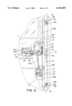
- FIG. 1 is a partial perspective view of, for example, a recreational vehicle having a door including a latch mechanism according to the present invention.
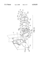
- FIG. 2 is a partial cut-away view of the door shown in FIG. 1 illustrating a latch mechanism according to one embodiment of the present invention in the closed and unlocked position.
- FIG. 3 is an exploded view showing three cams that are components of the latch mechanism shown in FIG. 2.
- FIG. 4 is a front elevational view of the cams of FIG. 3 in their operational positions.
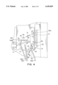
- FIG. 5 is an exploded view showing a handle and cam that are components of the latch mechanism shown in FIG. 2.
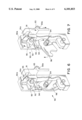
- FIG. 6 is a partial cut-away view of a latch assembly that is a component of the latch mechanism shown in FIG. 2 in the latched position.
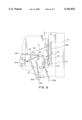
- FIG. 7 is a partial cut-away view of a latch assembly that is a component of the latch mechanism shown in FIG. 2 in the open position.
- FIG. 8 is a partial cut-away view illustrating the latch mechanism of FIG. 2 being opened by operation of a first handle.
- FIG. 9 illustrates the movement of the cams shown in FIG. 3 when the first handle is operated as shown in FIG. 8.
- FIG. 10 is a partial cut-away view illustrating the latch mechanism of FIG. 2 being opened by operation of a second handle.
- FIG. 1 is a partial perspective view of, for example, a recreational vehicle 10 including a door 11 employing a latch mechanism according to the present invention.
- FIG. 2 is a partial cut-away view of the door shown in FIG. 1 illustrating the components of a latch mechanism according to one embodiment of the present invention in the latched position.
- the door includes a first frame member 12 and a second frame member 13.
- the latch mechanism generally includes a first cam 20, a second cam 30, a third cam 40, a first handle 50, a first lock 60, a second handle 70, a second lock 80, a first and second latches 90, a third latch 110, a third lock 120, and a plurality of connecting rods 130a-j.
- First cam 20 (FIG. 3) includes a first surface 21, a second surface 22, a first finger 23, a second finger 24 and a third finger 25.
- Second finger 24 is offset from and extends above first surface 21.
- the arrangement of second finger 24 and third finger 25 leaves a space 26 located between second finger 24 and third finger 25.
- First finger 23 is provided with an opening 23a.
- Second finger 24 is similarly provided with an opening 24a.
- Another opening 27 is formed through first surface 21 and second surface 22.
- Second cam 30 (FIG. 3) includes a first surface 31 and a second surface 32.
- a projection 33 extends above first surface 31 and below second surface 32, so that projection 33 extends farther beyond the first surface 31 than the second surface 32.
- Second cam 30 further includes a first finger 34 and a second finger 35 arranged such that there is a space 36 between fingers 34 and 35.
- Second cam 30 further includes a plurality of openings 31a-d extending through first surface 31 and second surface 32 of second cam 30.
- Third cam 40 (FIG. 3) includes a first surface 41 and a second surface 42. Third cam 40 further includes a first finger 43, a second finger 44, a third finger 45 and a fourth finger 46. Second, third and fourth fingers 44, 45 and 46 are located on a raised portion of third cam 40 above first surface 41. Third finger 45 includes an upturned end 47 that extends above the remainder of third finger 45, second finger 44 and fourth finger 46. Second finger 44 and third finger 45 are arranged so as to provide a space 48 therebetween. In similar fashion, third finger 47 and fourth finger 46 are positioned so as to leave a space 49 therebetween. A plurality of openings 41a-e extend through first surface 41 and second surface 42 of third cam 40. An opening 44a extends through second finger 44. Similarly, another opening 45a extends through third cam 40 near second finger 44 and third finger 45. Openings 46a and 46b extend through fourth finger 46.
- cams 20, 30 and 40 are secured to frame member 12 through a bracket assembly 14.
- first cam 20 is secured to bracket assembly 14 by inserting a screw, rivet or similar fastener 12a through opening 27 and into bracket assembly 14.
- first cam 20 must be secured in such a manner that first cam 20 may rotate about fastener 12a.
- third cam 40 is secured to bracket assembly 14 by inserting fasteners 12b and 12c through openings 41d and 41e. Note that the opening 12d through which fastener 12c extends is elongated such that as third cam 40 pivots about fastener 12b, fastener 12c moves within that opening.
- Second cam 30 is positioned such that a portion of projection 33 is located in space 26 between second finger 24 and third finger 25 of cam 20 and end 47 of third finger 45 is located in space 36 between fingers 34 and 35 of second cam 30. In this position, extension 33 extends through opening 44a in third cam 40. A fastener 12e is inserted through opening 31b in second cam 30 and into opening 45a in third cam 40.
- a first spring s1 is secured at one end to bracket assembly 14 and at the other end to third cam 40 by inserting through opening 41a as shown.
- a second spring s2 is connected at one end to cam 30 by inserting through opening 31d and at the other end to third cam 40 by inserting through opening 46b as shown.
- First handle 50 (FIG. 2), in the embodiment shown, is secured to bracket assembly 14 so as to include a free end 51 and a pivoting end 52.
- Lock 60 is located below first handle 50. As described in further detail below, lock 60 is operated by sliding it in the directions indicated by the arrows.
- second handle 70 in the embodiment shown, is a paddle-type handle pivotally secured to a housing 71.
- Housing 71 is in turn secured to frame member 12 by a bracket assembly 15.
- Handle 70 includes a finger 72 secured to one end thereof.
- a cam 80 is secured to the housing 71.
- Cam 80 includes a first surface 81, a second surface 82, a first finger 83, a second finger 84, a third finger 85, and a fourth finger 86.
- First finger 83, second finger 84, and third finger 85 are offset and raised above first surface 81.
- Fourth finger 86 includes an upturned end 87 extending substantially vertically from first surface 81.
- An opening 81a is formed through first surface 81 and second surface 82. Openings 83a and 85a are formed in first finger 83 and second finger 85, respectively.
- An opening 87a is formed in upturned end 87 of third finger 86.
- Fourth cam 80 is attached to housing 71 by inserting a fastener 12f through housing 71 and opening 81a.
- Cam 80 is secured to housing 71 so as to be able to rotate about fastener 12f.
- One end of a spring s3 is secured to upturned end 87 through opening 87a as shown and the other end is secured to housing 71 as shown.
- Cam 80 is positioned such that finger 72 of handle 70 contacts second finger 84 of cam 80.
- a lock assembly 73 is secured to housing 71 and includes a finger 74 extending therefrom having opening 74a therein.
- Latches 90 in the embodiment shown, each include housing 90a.
- Each latch 90 further includes a cam member 91 having a first finger 92 and a second finger 93 with an opening 93a therein.
- Cam 91 is pivotally connected to frame member 13 by a fastener 91a extending through opening.
- Latch 90 further includes a pawl 94 pivotally connected to housing 90a.
- Pawl 94 includes a finger 95 in contact with finger 92 on cam 91.
- Latch 90 further includes a catch 96.
- Catch 96 is notched for engaging pawl 94 as shown.
- Both catch 96 and pawl 94 are pivotally attached to housing 90a.
- Catch 96 and pawl 94 are biased by springs s4 and s5. In particular, spring s4 biases catch 96 into the open position as shown in FIG. 7. Spring s5 biases pawl 94 downward as shown in FIG. 6.
- connecting rods 130a-130f The various components described above are connected by a plurality of connecting rods 130a-130f.
- Connecting rod 130a engages opening 93a of one cam 91 and opening 23a of cam 20.
- Connecting rod 130b engages opening 24a of cam 20 and opening 93a of the other cam 91.
- Connecting rod 130c engages opening 31c of cam 30 and opening 74a of finger 74.
- Connecting rod 130d engages opening 31a of cam 30 and is attached at the other end to lock 60.
- Connecting rod 130e engages opening 41c of cam 40 and opening 83a of cam 80.
- Connecting rod 130f engages opening 41b of cam 40 and pivotal end 52 of handle 50.
- FIG. 2 shows the door in the latched but unlocked position.
- each catch 96 engages a post 160 attached to frame member 13.
- Lock 60 is positioned such that projection 33 engages finger 25 of cam 20.
- handle 50 is pivoted such that connecting rod 130f pulls on cam 40, causing it to rotate in a counter-clockwise direction.
- cam 40 rotates in a counter-clockwise direction
- end 47 of finger 45 on cam 40 engages finger 35 on cam 30, also causing it to rotate in a counter-clockwise direction.
- cam 30 rotates in a counter-clockwise direction
- projection 33 bears against finger 25 of cam 20 causing cam 20 to rotate in a clockwise direction.
- connecting rod 130a is pulled downward and connecting rod 130b is pulled upward.
- This causes cams 96 to rotate.
- fingers 92 cause pawls 94 to rotate out of engagement from the notched portion of catches 96.
- the biasing force of spring s4 causes catches 96 to rotate out of engagement with posts 160.
- Door 11 may also be operated by pivoting handle 70 (FIG. 10). As this occurs, finger 72 engages finger 84 of cam 80 and causes it to rotate in a clockwise direction. As this occurs, movement of cam 80 applies a downward force to connecting rod 130 thereby causing cam 40 to rotate in a counterclockwise direction. This movement of cam 40 disengages catches 96 from posts 160 as described above.
- lock 60 can be used to disengage projection 33 from finger 25. To do so, lock 60 is slid away from cam 30. This causes connecting rod 130d to move cam 30 such that projection 33 is no longer engaged with finger 25. Accordingly, if either handle is then operated, although cams 40 and 30 will rotate, cam 20 will remain stationary and the door will remain latched. Similarly, using a key to lock the door via lock 80 causes connecting rod 130c to move cam 30 such that projection 33 no longer engages finger 25. Again, operating either handle will cause cams 40 and 30 to rotate, but cam 20 will remain stationary. A third way to lock the door is via lock 120. Lock 120 is a dead bolt type lock. When the lock is engaged, dead bolt 110 extends into frame member 13. In this manner, even if locks 60 and 80 are unlocked, thereby allowing operation of latches 90, the door may not be opened due to the engagement of dead bolt 110 frame member 13.
Abstract
Description
Claims (37)
Priority Applications (1)
| Application Number | Priority Date | Filing Date | Title |
|---|---|---|---|
| US09/221,905 US6101853A (en) | 1998-12-28 | 1998-12-28 | Door and latch mechanism |
Applications Claiming Priority (1)
| Application Number | Priority Date | Filing Date | Title |
|---|---|---|---|
| US09/221,905 US6101853A (en) | 1998-12-28 | 1998-12-28 | Door and latch mechanism |
Publications (1)
| Publication Number | Publication Date |
|---|---|
| US6101853A true US6101853A (en) | 2000-08-15 |
Family
ID=22829912
Family Applications (1)
| Application Number | Title | Priority Date | Filing Date |
|---|---|---|---|
| US09/221,905 Expired - Lifetime US6101853A (en) | 1998-12-28 | 1998-12-28 | Door and latch mechanism |
Country Status (1)
| Country | Link |
|---|---|
| US (1) | US6101853A (en) |
Cited By (19)
| Publication number | Priority date | Publication date | Assignee | Title |
|---|---|---|---|---|
| US6331030B1 (en) * | 1999-08-13 | 2001-12-18 | Hehr International | Vehicle door with anti-flutter catch assembly, and method of preventing vehicle door flutter |
| EP1394344A1 (en) * | 2002-08-29 | 2004-03-03 | Kobelco Construction Machinery Co., Ltd. | Construction machine with door locking device |
| US20050029834A1 (en) * | 2002-08-27 | 2005-02-10 | Kobelco Construction Machinery Co., Ltd | Construction machine with front window-locking device |
| WO2005038175A1 (en) * | 2003-10-16 | 2005-04-28 | Daz Lock Pty Ltd | A security lock arrangement |
| AU2003262314B2 (en) * | 2002-11-21 | 2005-08-18 | Safecorp Financial Services Pty Ltd | Security Lock Mechanism |
| US20060049643A1 (en) * | 2004-09-08 | 2006-03-09 | Roussel Jerome P | Latch release mechanism |
| US20090033108A1 (en) * | 2007-08-01 | 2009-02-05 | International Truck Intellectual Property Company, Llc | Rotating disk system for a vehicle door latch assembly |
| US20090058106A1 (en) * | 2007-08-31 | 2009-03-05 | Bacon Bruce C | Handle actuator assembly for dropdown doors and the like |
| US20090241613A1 (en) * | 2008-03-25 | 2009-10-01 | Kia Motors Corporation | Direct connecting type door latch device for automobile |
| US20090267354A1 (en) * | 2008-04-24 | 2009-10-29 | Trimark Corporation | Unitary latch, blast lock, and release handle assembly for vehicle door |
| US20100154489A1 (en) * | 2008-12-22 | 2010-06-24 | Bacon Bruce C | Locking paddle handle latch assembly for closures and the like |
| CN102011528A (en) * | 2010-11-22 | 2011-04-13 | 宁波信泰机械有限公司 | Switching mechanism for two-way unlocking of sliding door |
| US20120272695A1 (en) * | 2011-04-27 | 2012-11-01 | Trimark Corporation | Door handle assembly for vehicle compartment |
| US8393187B2 (en) | 2008-12-22 | 2013-03-12 | Bauer Products, Inc. | Remotely operated locking paddle handle latch assembly |
| US20130219793A1 (en) * | 2012-02-23 | 2013-08-29 | Master Lock Company Llc | Door locking assemblies and arrangements |
| US9085919B2 (en) | 2008-12-22 | 2015-07-21 | Bauer Products, Inc. | Touch pad lock assembly |
| US9940767B2 (en) | 2008-12-22 | 2018-04-10 | Bauer Products, Inc. | Touch pad lock assembly |
| US10378237B2 (en) | 2008-12-22 | 2019-08-13 | Bauer Products, Inc. | Touch pad lock assembly with clutch system |
| US20210230908A1 (en) * | 2018-05-24 | 2021-07-29 | Hawa Sliding Solutions Ag | Lock, fitting, strike plate and closing device for sliding doors and sliding door system |
Citations (33)
| Publication number | Priority date | Publication date | Assignee | Title |
|---|---|---|---|---|
| US3065986A (en) * | 1959-07-03 | 1962-11-27 | Wilmot Breeden Ltd | Door fastenings |
| US3582120A (en) * | 1969-06-30 | 1971-06-01 | Chrysler Corp | Cargo door latching mechanism |
| US3679251A (en) * | 1970-10-19 | 1972-07-25 | Gen Motors Corp | Closure latch |
| US3844595A (en) * | 1971-10-28 | 1974-10-29 | Volkswagenwerk Ag | Door lock arrangement for automobiles |
| US3899202A (en) * | 1973-04-25 | 1975-08-12 | Ferro Mfg Corp | Automotive side door latch |
| US4379360A (en) * | 1980-07-07 | 1983-04-12 | Liberty Hardware Manufacturing Corp. | Method of making a hinge with an integral pintle |
| US4689976A (en) * | 1986-06-16 | 1987-09-01 | Tri/Mark Corporation | Pop-up handle assembly |
| US4762349A (en) * | 1986-09-19 | 1988-08-09 | Kabushikikaisha Anseikogyo | Latch for an automobile door |
| US4773683A (en) * | 1985-08-09 | 1988-09-27 | Ohi Seisakusho Co., Ltd. | Door lock device |
| US4775176A (en) * | 1986-09-22 | 1988-10-04 | Kabushikikaisha Anseikogyo | Automobile door latch |
| US4892338A (en) * | 1988-10-13 | 1990-01-09 | The Eastern Company | Plural point door lock and flush-mountable operating mechanism with detent |
| US4917412A (en) * | 1987-05-27 | 1990-04-17 | The Eastern Company | Vehicle door lock system providing a plurality of spaced rotary latches |
| JPH02112574A (en) * | 1988-10-19 | 1990-04-25 | Mitsui Mining & Smelting Co Ltd | Locking device for back door of van type automobile |
| US4951486A (en) * | 1989-11-07 | 1990-08-28 | Cleveland Hardware & Forging | Nested paddle lock assembly |
| US5042853A (en) * | 1990-06-06 | 1991-08-27 | Tri-Mark | Paddle latch assembly |
| US5046769A (en) * | 1990-08-06 | 1991-09-10 | General Motors Corporation | Door latch coupling arrangement |
| US5058937A (en) * | 1991-02-14 | 1991-10-22 | Tri/Mark Corporation | Flush door latch assembly |
| US5127686A (en) * | 1991-02-14 | 1992-07-07 | Tri-Mark Corporation | Door closure assembly |
| US5234237A (en) * | 1992-05-11 | 1993-08-10 | General Motors Corporation | Modular van door latch |
| US5299844A (en) * | 1992-10-30 | 1994-04-05 | Tri/Mark Corporation | Sealed latch assembly |
| US5308130A (en) * | 1992-12-18 | 1994-05-03 | General Motors Corporation | Vehicle door latch |
| US5360244A (en) * | 1993-03-09 | 1994-11-01 | Tri/Mark Corporation | Lock assembly |
| US5382060A (en) * | 1993-01-11 | 1995-01-17 | Amerock Corporation | Latching apparatus for double doors |
| US5410899A (en) * | 1993-04-22 | 1995-05-02 | Tri/Mark Corporation | Retainer clip for escutcheon assembly |
| US5595076A (en) * | 1993-10-29 | 1997-01-21 | The Eastern Company | Handle operable two-point latch and lock |
| US5603234A (en) * | 1994-05-13 | 1997-02-18 | Diebold, Incorporated | Multiple lock assembly |
| US5606882A (en) * | 1994-09-21 | 1997-03-04 | Tri/Mark Corporation | Lock assembly with interchangeable key plug |
| US5618068A (en) * | 1993-04-07 | 1997-04-08 | Mitsui Kinzoku Kogyo Kabushiki Kaisha | Door lock apparatus with automatic door closing mechanism |
| US5718465A (en) * | 1995-06-13 | 1998-02-17 | Mitsui Kinzoku Kogyo Kabushiki Kaisha | Child-proof for vehicle sliding door latch device |
| US5749611A (en) * | 1996-08-30 | 1998-05-12 | Chrysler Corporation | Door latch remote control assembly |
| US5769471A (en) * | 1995-09-04 | 1998-06-23 | Aisin Seiki Kabushiki Kaisha | Apparatus for unlocking a door lock for a vehicle |
| US5899508A (en) * | 1996-08-19 | 1999-05-04 | Atoma International Inc. | Double locking vehicle door latch |
| US5951069A (en) * | 1996-04-26 | 1999-09-14 | Aisin Seiki Kabushiki Kaisha | Door closing apparatus |
-
1998
- 1998-12-28 US US09/221,905 patent/US6101853A/en not_active Expired - Lifetime
Patent Citations (33)
| Publication number | Priority date | Publication date | Assignee | Title |
|---|---|---|---|---|
| US3065986A (en) * | 1959-07-03 | 1962-11-27 | Wilmot Breeden Ltd | Door fastenings |
| US3582120A (en) * | 1969-06-30 | 1971-06-01 | Chrysler Corp | Cargo door latching mechanism |
| US3679251A (en) * | 1970-10-19 | 1972-07-25 | Gen Motors Corp | Closure latch |
| US3844595A (en) * | 1971-10-28 | 1974-10-29 | Volkswagenwerk Ag | Door lock arrangement for automobiles |
| US3899202A (en) * | 1973-04-25 | 1975-08-12 | Ferro Mfg Corp | Automotive side door latch |
| US4379360A (en) * | 1980-07-07 | 1983-04-12 | Liberty Hardware Manufacturing Corp. | Method of making a hinge with an integral pintle |
| US4773683A (en) * | 1985-08-09 | 1988-09-27 | Ohi Seisakusho Co., Ltd. | Door lock device |
| US4689976A (en) * | 1986-06-16 | 1987-09-01 | Tri/Mark Corporation | Pop-up handle assembly |
| US4762349A (en) * | 1986-09-19 | 1988-08-09 | Kabushikikaisha Anseikogyo | Latch for an automobile door |
| US4775176A (en) * | 1986-09-22 | 1988-10-04 | Kabushikikaisha Anseikogyo | Automobile door latch |
| US4917412A (en) * | 1987-05-27 | 1990-04-17 | The Eastern Company | Vehicle door lock system providing a plurality of spaced rotary latches |
| US4892338A (en) * | 1988-10-13 | 1990-01-09 | The Eastern Company | Plural point door lock and flush-mountable operating mechanism with detent |
| JPH02112574A (en) * | 1988-10-19 | 1990-04-25 | Mitsui Mining & Smelting Co Ltd | Locking device for back door of van type automobile |
| US4951486A (en) * | 1989-11-07 | 1990-08-28 | Cleveland Hardware & Forging | Nested paddle lock assembly |
| US5042853A (en) * | 1990-06-06 | 1991-08-27 | Tri-Mark | Paddle latch assembly |
| US5046769A (en) * | 1990-08-06 | 1991-09-10 | General Motors Corporation | Door latch coupling arrangement |
| US5058937A (en) * | 1991-02-14 | 1991-10-22 | Tri/Mark Corporation | Flush door latch assembly |
| US5127686A (en) * | 1991-02-14 | 1992-07-07 | Tri-Mark Corporation | Door closure assembly |
| US5234237A (en) * | 1992-05-11 | 1993-08-10 | General Motors Corporation | Modular van door latch |
| US5299844A (en) * | 1992-10-30 | 1994-04-05 | Tri/Mark Corporation | Sealed latch assembly |
| US5308130A (en) * | 1992-12-18 | 1994-05-03 | General Motors Corporation | Vehicle door latch |
| US5382060A (en) * | 1993-01-11 | 1995-01-17 | Amerock Corporation | Latching apparatus for double doors |
| US5360244A (en) * | 1993-03-09 | 1994-11-01 | Tri/Mark Corporation | Lock assembly |
| US5618068A (en) * | 1993-04-07 | 1997-04-08 | Mitsui Kinzoku Kogyo Kabushiki Kaisha | Door lock apparatus with automatic door closing mechanism |
| US5410899A (en) * | 1993-04-22 | 1995-05-02 | Tri/Mark Corporation | Retainer clip for escutcheon assembly |
| US5595076A (en) * | 1993-10-29 | 1997-01-21 | The Eastern Company | Handle operable two-point latch and lock |
| US5603234A (en) * | 1994-05-13 | 1997-02-18 | Diebold, Incorporated | Multiple lock assembly |
| US5606882A (en) * | 1994-09-21 | 1997-03-04 | Tri/Mark Corporation | Lock assembly with interchangeable key plug |
| US5718465A (en) * | 1995-06-13 | 1998-02-17 | Mitsui Kinzoku Kogyo Kabushiki Kaisha | Child-proof for vehicle sliding door latch device |
| US5769471A (en) * | 1995-09-04 | 1998-06-23 | Aisin Seiki Kabushiki Kaisha | Apparatus for unlocking a door lock for a vehicle |
| US5951069A (en) * | 1996-04-26 | 1999-09-14 | Aisin Seiki Kabushiki Kaisha | Door closing apparatus |
| US5899508A (en) * | 1996-08-19 | 1999-05-04 | Atoma International Inc. | Double locking vehicle door latch |
| US5749611A (en) * | 1996-08-30 | 1998-05-12 | Chrysler Corporation | Door latch remote control assembly |
Non-Patent Citations (2)
| Title |
|---|
| Tri/Mark advertising brochure for 100 5000 System, Vehicle Door Hardware. * |
| Tri/Mark advertising brochure for 100-5000 System, Vehicle Door Hardware. |
Cited By (30)
| Publication number | Priority date | Publication date | Assignee | Title |
|---|---|---|---|---|
| US6331030B1 (en) * | 1999-08-13 | 2001-12-18 | Hehr International | Vehicle door with anti-flutter catch assembly, and method of preventing vehicle door flutter |
| US20050029834A1 (en) * | 2002-08-27 | 2005-02-10 | Kobelco Construction Machinery Co., Ltd | Construction machine with front window-locking device |
| US7044534B2 (en) | 2002-08-27 | 2006-05-16 | Kobelco Construction Machinery Co., Ltd. | Construction machine with front window-locking device |
| US7040687B2 (en) | 2002-08-29 | 2006-05-09 | Kobelco Construction Machinery Co., Ltd. | Construction machine with door locking device |
| EP1394344A1 (en) * | 2002-08-29 | 2004-03-03 | Kobelco Construction Machinery Co., Ltd. | Construction machine with door locking device |
| US20040041410A1 (en) * | 2002-08-29 | 2004-03-04 | Kobelco Construction Machinery Co., Ltd. | Construction machine with door locking device |
| AU2003262314B2 (en) * | 2002-11-21 | 2005-08-18 | Safecorp Financial Services Pty Ltd | Security Lock Mechanism |
| WO2005038175A1 (en) * | 2003-10-16 | 2005-04-28 | Daz Lock Pty Ltd | A security lock arrangement |
| US20080157542A1 (en) * | 2003-10-16 | 2008-07-03 | Daz Lock Pty Ltd | Security Lock Arrangement |
| US7591157B2 (en) | 2003-10-16 | 2009-09-22 | Daz Lock Pty Ltd | Security lock arrangement |
| US20060049643A1 (en) * | 2004-09-08 | 2006-03-09 | Roussel Jerome P | Latch release mechanism |
| US20090033108A1 (en) * | 2007-08-01 | 2009-02-05 | International Truck Intellectual Property Company, Llc | Rotating disk system for a vehicle door latch assembly |
| US7823933B2 (en) * | 2007-08-01 | 2010-11-02 | International Truck Intellectual Property Company, Llc | Rotating disk system for a vehicle door latch assembly |
| US20090058106A1 (en) * | 2007-08-31 | 2009-03-05 | Bacon Bruce C | Handle actuator assembly for dropdown doors and the like |
| US8419089B2 (en) | 2007-08-31 | 2013-04-16 | Bauer Products, Inc. | Handle actuator assembly for dropdown doors and the like |
| US20090241613A1 (en) * | 2008-03-25 | 2009-10-01 | Kia Motors Corporation | Direct connecting type door latch device for automobile |
| US20090267354A1 (en) * | 2008-04-24 | 2009-10-29 | Trimark Corporation | Unitary latch, blast lock, and release handle assembly for vehicle door |
| US8998275B2 (en) * | 2008-04-24 | 2015-04-07 | Trimark Corporation | Unitary latch, blast lock, and release handle assembly for vehicle door |
| US10378237B2 (en) | 2008-12-22 | 2019-08-13 | Bauer Products, Inc. | Touch pad lock assembly with clutch system |
| US8347667B2 (en) * | 2008-12-22 | 2013-01-08 | Bauer Products, Inc. | Locking paddle handle latch assembly for closures and the like |
| US8393187B2 (en) | 2008-12-22 | 2013-03-12 | Bauer Products, Inc. | Remotely operated locking paddle handle latch assembly |
| US20100154489A1 (en) * | 2008-12-22 | 2010-06-24 | Bacon Bruce C | Locking paddle handle latch assembly for closures and the like |
| US9940767B2 (en) | 2008-12-22 | 2018-04-10 | Bauer Products, Inc. | Touch pad lock assembly |
| US9085919B2 (en) | 2008-12-22 | 2015-07-21 | Bauer Products, Inc. | Touch pad lock assembly |
| CN102011528A (en) * | 2010-11-22 | 2011-04-13 | 宁波信泰机械有限公司 | Switching mechanism for two-way unlocking of sliding door |
| CN102011528B (en) * | 2010-11-22 | 2012-10-24 | 宁波信泰机械有限公司 | Switching mechanism for two-way unlocking of sliding door |
| US9816299B2 (en) * | 2011-04-27 | 2017-11-14 | Trimark Corporation | Door handle assembly for vehicle compartment |
| US20120272695A1 (en) * | 2011-04-27 | 2012-11-01 | Trimark Corporation | Door handle assembly for vehicle compartment |
| US20130219793A1 (en) * | 2012-02-23 | 2013-08-29 | Master Lock Company Llc | Door locking assemblies and arrangements |
| US20210230908A1 (en) * | 2018-05-24 | 2021-07-29 | Hawa Sliding Solutions Ag | Lock, fitting, strike plate and closing device for sliding doors and sliding door system |
Similar Documents
| Publication | Publication Date | Title |
|---|---|---|
| US6101853A (en) | Door and latch mechanism | |
| JP3310960B2 (en) | Connecting device for inside lock button and lock lever in vehicle door latch device with double action mechanism | |
| US5044182A (en) | Automatic deadbolt | |
| US7204530B2 (en) | Vehicle door inside handle assembly | |
| US6962375B2 (en) | Rotary latches | |
| US20030159478A1 (en) | Fixed-leaf lock machanism | |
| JP2002502002A (en) | Slam latch with opposing slides | |
| CA2183618A1 (en) | Double-locking vehicle door latches and a double-locking sub-assembly therefor | |
| US20070200356A1 (en) | Door Entry Latch | |
| EP1797259B1 (en) | Rotary pawl latch | |
| US4113294A (en) | Anti-theft clip | |
| US5785365A (en) | Anti-snagging striker | |
| US6973810B2 (en) | Toolbox rotary latch | |
| US6431617B1 (en) | Door mechanism | |
| JPH11513764A (en) | Vehicle door latch assembly | |
| US6431619B1 (en) | Door mechanism | |
| KR100581735B1 (en) | Dead bolt locking structure of doorlock locking mechanism | |
| US11851913B2 (en) | Hook bolt for door lock | |
| US20040144142A1 (en) | Modular vehicle door lock and latch system and method | |
| GB2281756A (en) | An actuator handle assembly | |
| CA2139991A1 (en) | Panic exit door mechanism | |
| KR101089821B1 (en) | Door latch assembly | |
| CN215889679U (en) | Door lock, door module and vehicle | |
| JP3502573B2 (en) | Rubber stopper in vehicle door latch device | |
| JPS59158877A (en) | Door lock device for two-operation type locking and unlocking system |
Legal Events
| Date | Code | Title | Description |
|---|---|---|---|
| AS | Assignment |
Owner name: MONACO COACH CORPORATION, INDIANA Free format text: ASSIGNMENT OF ASSIGNORS INTEREST;ASSIGNOR:HERR, DEVON L.;REEL/FRAME:010112/0726 Effective date: 19990720 |
|
| STCF | Information on status: patent grant |
Free format text: PATENTED CASE |
|
| FPAY | Fee payment |
Year of fee payment: 4 |
|
| FPAY | Fee payment |
Year of fee payment: 8 |
|
| REMI | Maintenance fee reminder mailed | ||
| AS | Assignment |
Owner name: ABLECO FINANCE LLC, AS COLLATERAL AGENT, NEW YORK Free format text: GRANT OF A SECURITY INTEREST;ASSIGNOR:MONACO COACH CORPORATION;REEL/FRAME:021805/0109 Effective date: 20081106 Owner name: ABLECO FINANCE LLC, AS COLLATERAL AGENT,NEW YORK Free format text: GRANT OF A SECURITY INTEREST;ASSIGNOR:MONACO COACH CORPORATION;REEL/FRAME:021805/0109 Effective date: 20081106 |
|
| AS | Assignment |
Owner name: BANK OF AMERICA, N.A., AS ADMINISTRATIVE AGENT, CA Free format text: SECURITY AGREEMENT;ASSIGNOR:MONACO COACH CORPORATION, A DELAWARE CORPORATION;REEL/FRAME:021817/0358 Effective date: 20081106 Owner name: BANK OF AMERICA, N.A., AS ADMINISTRATIVE AGENT,CAL Free format text: SECURITY AGREEMENT;ASSIGNOR:MONACO COACH CORPORATION, A DELAWARE CORPORATION;REEL/FRAME:021817/0358 Effective date: 20081106 |
|
| FPAY | Fee payment |
Year of fee payment: 12 |
|
| AS | Assignment |
Owner name: BISON MANUFACTURING, LLC, INDIANA Free format text: BANKRUPTCY COURT ORDER AUTHORIZING THE SALE OF ASSETS FREE AND CLEAR OF ALL LIENS;ASSIGNOR:UNITED STATES BANKRUPTCY COURT FOR THE DISTRICT OF DELAWARE;REEL/FRAME:030315/0901 Effective date: 20090522 Owner name: ROADMASTER LLC, INDIANA Free format text: BANKRUPTCY COURT ORDER AUTHORIZING THE SALE OF ASSETS FREE AND CLEAR OF ALL LIENS;ASSIGNOR:UNITED STATES BANKRUPTCY COURT FOR THE DISTRICT OF DELAWARE;REEL/FRAME:030315/0901 Effective date: 20090522 Owner name: MONACO COACH CORPORATION, OREGON Free format text: BANKRUPTCY COURT ORDER AUTHORIZING THE SALE OF ASSETS FREE AND CLEAR OF ALL LIENS;ASSIGNOR:UNITED STATES BANKRUPTCY COURT FOR THE DISTRICT OF DELAWARE;REEL/FRAME:030315/0901 Effective date: 20090522 Owner name: R-VISION, INC., INDIANA Free format text: BANKRUPTCY COURT ORDER AUTHORIZING THE SALE OF ASSETS FREE AND CLEAR OF ALL LIENS;ASSIGNOR:UNITED STATES BANKRUPTCY COURT FOR THE DISTRICT OF DELAWARE;REEL/FRAME:030315/0901 Effective date: 20090522 |
|
| AS | Assignment |
Owner name: INTERNATIONAL TRUCK INTELLECTUAL PROPERTY COMPANY, Free format text: ASSIGNMENT OF ASSIGNORS INTEREST;ASSIGNOR:MONACO COACH CORPORATION;REEL/FRAME:030349/0085 Effective date: 20090604 |
|
| AS | Assignment |
Owner name: MONACO RV, LLC, INDIANA Free format text: CHANGE OF NAME;ASSIGNOR:NAVISTAR RV, LLC;REEL/FRAME:030889/0201 Effective date: 20130516 Owner name: NAVISTAR RV, LLC, ILLINOIS Free format text: ASSIGNMENT OF ASSIGNORS INTEREST;ASSIGNOR:INTERNATIONAL TRUCK INTELLECTUAL PROPERTY COMPANY, LLC;REEL/FRAME:030874/0591 Effective date: 20130515 |
|
| AS | Assignment |
Owner name: REV RECREATION GROUP, INC., INDIANA Free format text: ASSIGNMENT OF ASSIGNORS INTEREST;ASSIGNOR:MONACO RV, LLC;REEL/FRAME:038201/0861 Effective date: 20160324 |
|
| AS | Assignment |
Owner name: DEUTSCHE BANK AG NEW YORK BRANCH, AS REVOLVING COL Free format text: GRANT OF SECURITY INTEREST IN PATENTS;ASSIGNOR:REV RECREATION GROUP, INC., FKA ALLIED RECREATION GROUP, INC.;REEL/FRAME:038502/0476 Effective date: 20160422 |
|
| AS | Assignment |
Owner name: REV RECREATION GROUP, INC. (FORMERLY ALLIED RECREA Free format text: RELEASE BY SECURED PARTY;ASSIGNOR:DEUTSCHE BANK AG NEW YORK BRANCH;REEL/FRAME:042328/0987 Effective date: 20170425 Owner name: CAPACITY OF TEXAS, INC., WISCONSIN Free format text: RELEASE BY SECURED PARTY;ASSIGNOR:DEUTSCHE BANK AG NEW YORK BRANCH;REEL/FRAME:042328/0987 Effective date: 20170425 Owner name: E-ONE, INC., FLORIDA Free format text: RELEASE BY SECURED PARTY;ASSIGNOR:DEUTSCHE BANK AG NEW YORK BRANCH;REEL/FRAME:042328/0987 Effective date: 20170425 Owner name: REV AMBULANCE GROUP ORLANDO, INC. (FORMERLY WHEELE Free format text: RELEASE BY SECURED PARTY;ASSIGNOR:DEUTSCHE BANK AG NEW YORK BRANCH;REEL/FRAME:042328/0987 Effective date: 20170425 Owner name: HALCORE GROUP, INC., OHIO Free format text: RELEASE BY SECURED PARTY;ASSIGNOR:DEUTSCHE BANK AG NEW YORK BRANCH;REEL/FRAME:042328/0987 Effective date: 20170425 Owner name: COLLINS BUS CORPORATION, KANSAS Free format text: RELEASE BY SECURED PARTY;ASSIGNOR:DEUTSCHE BANK AG NEW YORK BRANCH;REEL/FRAME:042328/0987 Effective date: 20170425 Owner name: KOVATCH MOBILE EQUIPMENT CORP., PENNSYLVANIA Free format text: RELEASE BY SECURED PARTY;ASSIGNOR:DEUTSCHE BANK AG NEW YORK BRANCH;REEL/FRAME:042328/0987 Effective date: 20170425 Owner name: REV AMBULANCE GROUP ORLANDO, INC. (FORMERLY WHEELED COACH INDUSTRIES, INC.), FLORIDA Free format text: RELEASE BY SECURED PARTY;ASSIGNOR:DEUTSCHE BANK AG NEW YORK BRANCH;REEL/FRAME:042328/0987 Effective date: 20170425 Owner name: REV RECREATION GROUP, INC. (FORMERLY ALLIED RECREATION GROUP, INC. (FORMERLY FLEETWOOD RV, INC.)), INDIANA Free format text: RELEASE BY SECURED PARTY;ASSIGNOR:DEUTSCHE BANK AG NEW YORK BRANCH;REEL/FRAME:042328/0987 Effective date: 20170425 |