US6060193A - Battery for a mobile phone - Google Patents
Battery for a mobile phone Download PDFInfo
- Publication number
- US6060193A US6060193A US09/095,150 US9515098A US6060193A US 6060193 A US6060193 A US 6060193A US 9515098 A US9515098 A US 9515098A US 6060193 A US6060193 A US 6060193A
- Authority
- US
- United States
- Prior art keywords
- battery
- recess
- casing
- tab
- locking element
- Prior art date
- Legal status (The legal status is an assumption and is not a legal conclusion. Google has not performed a legal analysis and makes no representation as to the accuracy of the status listed.)
- Expired - Lifetime
Links
Images

Classifications
-
- H—ELECTRICITY
- H04—ELECTRIC COMMUNICATION TECHNIQUE
- H04M—TELEPHONIC COMMUNICATION
- H04M1/00—Substation equipment, e.g. for use by subscribers
- H04M1/02—Constructional features of telephone sets
- H04M1/0202—Portable telephone sets, e.g. cordless phones, mobile phones or bar type handsets
- H04M1/026—Details of the structure or mounting of specific components
- H04M1/0262—Details of the structure or mounting of specific components for a battery compartment
-
- H—ELECTRICITY
- H01—ELECTRIC ELEMENTS
- H01M—PROCESSES OR MEANS, e.g. BATTERIES, FOR THE DIRECT CONVERSION OF CHEMICAL ENERGY INTO ELECTRICAL ENERGY
- H01M50/00—Constructional details or processes of manufacture of the non-active parts of electrochemical cells other than fuel cells, e.g. hybrid cells
- H01M50/20—Mountings; Secondary casings or frames; Racks, modules or packs; Suspension devices; Shock absorbers; Transport or carrying devices; Holders
- H01M50/204—Racks, modules or packs for multiple batteries or multiple cells
- H01M50/207—Racks, modules or packs for multiple batteries or multiple cells characterised by their shape
- H01M50/213—Racks, modules or packs for multiple batteries or multiple cells characterised by their shape adapted for cells having curved cross-section, e.g. round or elliptic
-
- Y—GENERAL TAGGING OF NEW TECHNOLOGICAL DEVELOPMENTS; GENERAL TAGGING OF CROSS-SECTIONAL TECHNOLOGIES SPANNING OVER SEVERAL SECTIONS OF THE IPC; TECHNICAL SUBJECTS COVERED BY FORMER USPC CROSS-REFERENCE ART COLLECTIONS [XRACs] AND DIGESTS
- Y02—TECHNOLOGIES OR APPLICATIONS FOR MITIGATION OR ADAPTATION AGAINST CLIMATE CHANGE
- Y02E—REDUCTION OF GREENHOUSE GAS [GHG] EMISSIONS, RELATED TO ENERGY GENERATION, TRANSMISSION OR DISTRIBUTION
- Y02E60/00—Enabling technologies; Technologies with a potential or indirect contribution to GHG emissions mitigation
- Y02E60/10—Energy storage using batteries
Definitions
- the invention relates to a mobile phone battery that can be mounted in place by pushing it in the horizontal plane, i.e. in the direction of the phone's surface into a recess formed by the phone's casing, and it comprises at least one locking element which engages with a catch in the recess, preventing the battery from being pulled loose horizontally, tabs on the sides of the battery, which slide under the tabs on the sides of the recess to hold the battery in place in the vertical direction as well as a spring which loads the locking element and when pressed releases the locking element from the catch to enable the battery to be pulled loose.
- the battery of a mobile phone is typically a rather flat slablike piece which attaches retractably to the bottom side of the phone, fitting into a recess that has been formed for it. Fitting the battery into place is accomplished by a pushing motion in the direction of the phone's bottom surface, at the end of which the battery locks into the recess when the springloaded locking element engages with the catches that have been provided in the recess.
- the spring is incorporated in a push button which when pressed releases the battery's locking element from the catches in the recess, allowing the battery to be removed by means of a pulling motion in the opposite direction to the pushing motion.
- the mentioned locking elements belonging to the battery are positioned at the end of the battery such that the end, when the battery is pushed into place in the recess in the phone, comes up against the end of the recess which is opposite it, the end being equipped with catches corresponding to the locking elements.
- the locking elements and the catches in the recess hold the battery in place in the horizontal direction, i.e. in the direction of the phone's bottom surface.
- Vertical detachment of the battery is prevented by the tabs on the sides of the battery, which, when the battery is mounted in place, have been pushed under the corresponding tabs that are provided on the sides of the recess.
- the purpose of the present invention is to provide a solution whereby fitting of the battery into the recess of the phone's casing can be simplified.
- the battery according to the invention is characterized in that the locking element is located on the side of the battery and is arranged so as to lock, viewed from the pushing direction, behind the tab on the side of the recess, the tab acting as a catch.
- the invention means, in particular, a further simplification of the recess formed to receive the phone's battery. Since the catch on the side of the recess acts as an obstacle preventing the battery from moving out of its position horizontally, the catches at the end of the recess, which have belonged to the above described previously known solution model, can be omitted since they are not needed.
- the resulting advantages are a simplification of the manufacturing mould for the phone's casing as well as the possibility of designing the battery with a flatter contour than before.
- the first tab acts as an element that holds the battery in place simultaneously in the horizontal and vertical direction.
- FIG. 1 shows the casing of a mobile phone from the bottom side with the recess in it for a battery
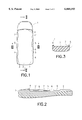
- FIG. 2 shows a longitudinal section of the casing, II--II, from FIG. 1,
- FIG. 3 shows a cross section of the casing, III--III, from FIG. 1,
- FIG. 4 is a side view of a battery that is fitted into the recess of the phone according to FIG. 1,
- FIG. 5 shows the battery with its locking parts as a sectional view V--V from FIG. 4,
- FIG. 6 shows the locking part of the battery according to FIGS. 4 and 5
- FIG. 7 depicts the fitting into place of the battery according to FIG. 4 by pushing it into the recess in the casing of the phone according to FIGS. 1-3,
- FIG. 8 shows a phone in which the battery is fitted into the recess
- FIG. 9 shows, in a larger scale, the locking between the catch incorporated in the recess and the locking element belonging to the battery.
- FIGS. 1-3 show the casing 1 of a mobile phone at the bottom of which is a wide and shallow recess 2 which runs in the direction of the top of the phone and into which the phone's battery can be fitted.
- the recess 2 comprises the longitudinal sides 3 of the casing 1 as well as a lateral end 4 which is arranged to come up against the end of the battery that is pushed into place.
- the tabs that are nearest to the end 4 of the recess have bevels 8 which are seen in FIG. 2 and are oriented towards the direction from which the battery is pushed into place.
- the mobile phone battery 9 according to FIGS. 1-3 which is shown in FIG. 4, is a fairly flat piece that is contoured to fit into the recess 2 in the phone as shown in FIG. 8.
- tabs 10, 10' On the sides of the battery 9 are tabs 10, 10', which can be pushed into the grooves 7 in the sides 3 of the recess in such a way that they seat under the tabs 5, 5' in the sides of the recess.
- the battery 9 is equipped with a spring-loaded locking piece 11 according to FIG. 6, which comprises a protruding locking element 12 that is wedge-shaped at its pointed end and positioned symmetrically on both sides of the battery.
- the locking piece 11 is positioned near the tip 13 of the battery in such a way that the locking elements 12 are located immediately in front of the frontmost tabs 10' along the sides of the battery.
- the spring 14 that is located between the locking elements 12 holds the locking piece 11 in a raised position such that the locking elements 12 are located in the normal state somewhat higher up than the tabs 10' along the sides of the battery as can be seen, for example, in FIG. 4.
- the locking elements 12 can nevertheless be brought to the same level as the tabs 10' on the sides of the battery.
- FIGS. 7-9 The fitting of the battery 9 into place in the recess 2 in the casing 1 of the phone and its locking into it are shown in FIGS. 7-9.
- the battery 9 is placed in the recess 2 first in such a way that the tabs 10, 10' on the sides of the battery and the locking elements 12 are positioned at the spaces 6 between the tabs 5 on the sides 3 of the recess. Thereafter the battery 9 is pushed in the direction of the bottom surface of the phone towards the end 4 of the recess, i.e. to the left in FIG.
- the tabs 10, 10' on the sides of the battery 9 remain in the grooves 7 underneath the side tabs 5, 5' of the recess, as likewise can be seen in FIG. 9.
Abstract
Description
Claims (5)
Applications Claiming Priority (2)
| Application Number | Priority Date | Filing Date | Title |
|---|---|---|---|
| FI972570 | 1997-06-17 | ||
| FI972570A FI105521B (en) | 1997-06-17 | 1997-06-17 | Cell phone battery |
Publications (1)
| Publication Number | Publication Date |
|---|---|
| US6060193A true US6060193A (en) | 2000-05-09 |
Family
ID=8549068
Family Applications (1)
| Application Number | Title | Priority Date | Filing Date |
|---|---|---|---|
| US09/095,150 Expired - Lifetime US6060193A (en) | 1997-06-17 | 1998-06-10 | Battery for a mobile phone |
Country Status (4)
| Country | Link |
|---|---|
| US (1) | US6060193A (en) |
| EP (1) | EP0892447B1 (en) |
| DE (1) | DE69800377T2 (en) |
| FI (1) | FI105521B (en) |
Cited By (28)
| Publication number | Priority date | Publication date | Assignee | Title |
|---|---|---|---|---|
| EP1182716A2 (en) * | 2000-08-23 | 2002-02-27 | Nokia Mobile Phones Ltd. | Battery lock |
| US6485861B2 (en) * | 1998-04-06 | 2002-11-26 | Sony Corporation | Battery pack, battery charger and an electronic device using a battery pack |
| US20030003949A1 (en) * | 2001-07-02 | 2003-01-02 | Lg Electronics Inc. | Mobile phone |
| US20030012370A1 (en) * | 2001-07-02 | 2003-01-16 | Harri Turunen | Locking arrangement for a cover part of a subscriber terminal device |
| US20030022633A1 (en) * | 2001-07-26 | 2003-01-30 | Ming-Te Chen | Mobile phone with battery latch |
| US20030124200A1 (en) * | 1999-06-22 | 2003-07-03 | Stone Kevin R. | Cartilage enhancing food supplements with sucralose and methods of preparing the same |
| US20040001997A1 (en) * | 2002-06-27 | 2004-01-01 | Vocollect, Inc. | Wearable terminal |
| US20040038121A1 (en) * | 2002-08-24 | 2004-02-26 | Samsung Electronics Co., Ltd. | Battery pack locking device for portable wireless terminal |
| US20040126666A1 (en) * | 2002-05-13 | 2004-07-01 | Shuguang Cao | Ion conductive block copolymers |
| US20050272479A1 (en) * | 2004-06-02 | 2005-12-08 | James Infanti | Slim line battery pack |
| US20060121338A1 (en) * | 2004-12-03 | 2006-06-08 | Fih Co.,Ltd | Battery cover assembly and related housing assembly |
| US20060176016A1 (en) * | 2005-02-09 | 2006-08-10 | Kok Yeoh S | Pocket personal computer with mobile phone |
| US20060226804A1 (en) * | 2005-04-12 | 2006-10-12 | Inventec Corporation | Mobil phone battery replacement apparatus |
| US20070243457A1 (en) * | 2006-04-12 | 2007-10-18 | Andres Viduya | Electronic device with multiple battery contacts |
| USD613267S1 (en) | 2008-09-29 | 2010-04-06 | Vocollect, Inc. | Headset |
| US7773767B2 (en) | 2006-02-06 | 2010-08-10 | Vocollect, Inc. | Headset terminal with rear stability strap |
| US20100279163A1 (en) * | 2009-04-30 | 2010-11-04 | Chi Mei Communication Systems, Inc. | Battery cover latch assembly |
| USD626949S1 (en) | 2008-02-20 | 2010-11-09 | Vocollect Healthcare Systems, Inc. | Body-worn mobile device |
| US7885419B2 (en) | 2006-02-06 | 2011-02-08 | Vocollect, Inc. | Headset terminal with speech functionality |
| USD643013S1 (en) | 2010-08-20 | 2011-08-09 | Vocollect Healthcare Systems, Inc. | Body-worn mobile device |
| USD643400S1 (en) | 2010-08-19 | 2011-08-16 | Vocollect Healthcare Systems, Inc. | Body-worn mobile device |
| US8128422B2 (en) | 2002-06-27 | 2012-03-06 | Vocollect, Inc. | Voice-directed portable terminals for wireless communication systems |
| US8160287B2 (en) | 2009-05-22 | 2012-04-17 | Vocollect, Inc. | Headset with adjustable headband |
| US8298696B1 (en) | 2008-06-03 | 2012-10-30 | Eddie Dana | Battery systems and methods thereof |
| US8386261B2 (en) | 2008-11-14 | 2013-02-26 | Vocollect Healthcare Systems, Inc. | Training/coaching system for a voice-enabled work environment |
| US8417185B2 (en) | 2005-12-16 | 2013-04-09 | Vocollect, Inc. | Wireless headset and method for robust voice data communication |
| US8438659B2 (en) | 2009-11-05 | 2013-05-07 | Vocollect, Inc. | Portable computing device and headset interface |
| US8659397B2 (en) | 2010-07-22 | 2014-02-25 | Vocollect, Inc. | Method and system for correctly identifying specific RFID tags |
Families Citing this family (4)
| Publication number | Priority date | Publication date | Assignee | Title |
|---|---|---|---|---|
| FI111427B (en) | 2001-07-02 | 2003-07-15 | Microcell S A Luxembourg Zweig | Locking device for a subscriber terminal |
| WO2005060116A2 (en) * | 2003-12-18 | 2005-06-30 | Thomson Licensing | Housing assembly for an electronic device |
| ATE382537T1 (en) * | 2004-01-07 | 2008-01-15 | Campagnolo Srl | COMBINED ACCESSORY HOLDER AND ELECTRONIC CONTROL FOR A BICYCLE |
| KR100761480B1 (en) * | 2006-05-26 | 2007-09-27 | 삼성전자주식회사 | Portable electric device and camera |
Citations (8)
| Publication number | Priority date | Publication date | Assignee | Title |
|---|---|---|---|---|
| US4904549A (en) * | 1988-11-04 | 1990-02-27 | Motorola, Inc. | Battery housing with integral latch and positive displacement apparatus |
| US5136229A (en) * | 1991-07-15 | 1992-08-04 | Galvin Jay M | Power pack device |
| US5308716A (en) * | 1993-09-20 | 1994-05-03 | Motorola, Inc. | Battery pack retention apparatus |
| EP0743689A1 (en) * | 1992-05-29 | 1996-11-20 | Sony Corporation | Battery cartridge having a recess for detecting misuse and/or recessed terminals |
| US5604050A (en) * | 1995-06-13 | 1997-02-18 | Motorola Inc. | Latching mechanism and method of latching thereby |
| US5625271A (en) * | 1995-10-20 | 1997-04-29 | Motorola, Inc. | Battery charger adapter and method therefor |
| US5660945A (en) * | 1996-05-30 | 1997-08-26 | Motorola, Inc. | Battery having a latching mechanism with torsion plates |
| US5665485A (en) * | 1994-06-03 | 1997-09-09 | Kokusai Electric Co., Ltd. | Splashproof construction for portable type electronic device |
Family Cites Families (1)
| Publication number | Priority date | Publication date | Assignee | Title |
|---|---|---|---|---|
| US5607792A (en) * | 1996-02-05 | 1997-03-04 | Motorola, Inc. | Battery latch |
-
1997
- 1997-06-17 FI FI972570A patent/FI105521B/en not_active IP Right Cessation
-
1998
- 1998-06-10 US US09/095,150 patent/US6060193A/en not_active Expired - Lifetime
- 1998-06-16 DE DE69800377T patent/DE69800377T2/en not_active Expired - Lifetime
- 1998-06-16 EP EP98660059A patent/EP0892447B1/en not_active Expired - Lifetime
Patent Citations (8)
| Publication number | Priority date | Publication date | Assignee | Title |
|---|---|---|---|---|
| US4904549A (en) * | 1988-11-04 | 1990-02-27 | Motorola, Inc. | Battery housing with integral latch and positive displacement apparatus |
| US5136229A (en) * | 1991-07-15 | 1992-08-04 | Galvin Jay M | Power pack device |
| EP0743689A1 (en) * | 1992-05-29 | 1996-11-20 | Sony Corporation | Battery cartridge having a recess for detecting misuse and/or recessed terminals |
| US5308716A (en) * | 1993-09-20 | 1994-05-03 | Motorola, Inc. | Battery pack retention apparatus |
| US5665485A (en) * | 1994-06-03 | 1997-09-09 | Kokusai Electric Co., Ltd. | Splashproof construction for portable type electronic device |
| US5604050A (en) * | 1995-06-13 | 1997-02-18 | Motorola Inc. | Latching mechanism and method of latching thereby |
| US5625271A (en) * | 1995-10-20 | 1997-04-29 | Motorola, Inc. | Battery charger adapter and method therefor |
| US5660945A (en) * | 1996-05-30 | 1997-08-26 | Motorola, Inc. | Battery having a latching mechanism with torsion plates |
Non-Patent Citations (1)
| Title |
|---|
| European Search Report Aug. 28, 1998. * |
Cited By (50)
| Publication number | Priority date | Publication date | Assignee | Title |
|---|---|---|---|---|
| US6485861B2 (en) * | 1998-04-06 | 2002-11-26 | Sony Corporation | Battery pack, battery charger and an electronic device using a battery pack |
| US20030124200A1 (en) * | 1999-06-22 | 2003-07-03 | Stone Kevin R. | Cartilage enhancing food supplements with sucralose and methods of preparing the same |
| US6455188B1 (en) * | 2000-08-23 | 2002-09-24 | Nokia Mobile Phones Ltd. | Battery lock |
| EP1182716A3 (en) * | 2000-08-23 | 2003-10-01 | Nokia Corporation | Battery lock |
| EP1182716A2 (en) * | 2000-08-23 | 2002-02-27 | Nokia Mobile Phones Ltd. | Battery lock |
| US20030003949A1 (en) * | 2001-07-02 | 2003-01-02 | Lg Electronics Inc. | Mobile phone |
| US20030012370A1 (en) * | 2001-07-02 | 2003-01-16 | Harri Turunen | Locking arrangement for a cover part of a subscriber terminal device |
| US7218731B2 (en) * | 2001-07-02 | 2007-05-15 | Flextronics Sales & Marketing(A-P)Ltd. | Locking arrangement for a cover part of a subscriber terminal device |
| US7346366B2 (en) * | 2001-07-02 | 2008-03-18 | Lg Electronics, Inc. | Mobile phone |
| US6975842B2 (en) * | 2001-07-26 | 2005-12-13 | Benq Corporation | Mobile phone with battery latch |
| US20030022633A1 (en) * | 2001-07-26 | 2003-01-30 | Ming-Te Chen | Mobile phone with battery latch |
| US20040126666A1 (en) * | 2002-05-13 | 2004-07-01 | Shuguang Cao | Ion conductive block copolymers |
| US20040001997A1 (en) * | 2002-06-27 | 2004-01-01 | Vocollect, Inc. | Wearable terminal |
| US20050272401A1 (en) * | 2002-06-27 | 2005-12-08 | Vocollect, Inc. | Environmentally-sealed portable terminal |
| US7052799B2 (en) | 2002-06-27 | 2006-05-30 | Vocollect, Inc. | Wearable terminal with a battery latch mechanism |
| US8128422B2 (en) | 2002-06-27 | 2012-03-06 | Vocollect, Inc. | Voice-directed portable terminals for wireless communication systems |
| US7476462B2 (en) * | 2002-08-24 | 2009-01-13 | Samsung Electronics Co., Ltd | Battery pack locking device for portable wireless terminal |
| US20040038121A1 (en) * | 2002-08-24 | 2004-02-26 | Samsung Electronics Co., Ltd. | Battery pack locking device for portable wireless terminal |
| US20080193836A1 (en) * | 2004-06-02 | 2008-08-14 | Research In Motion Limited | Slim line battery pack |
| US7912515B2 (en) | 2004-06-02 | 2011-03-22 | Research In Motion Limited | Slim line battery pack |
| US8700104B2 (en) | 2004-06-02 | 2014-04-15 | Blackberry Limited | Slim line battery pack |
| US8213998B2 (en) | 2004-06-02 | 2012-07-03 | Research In Motion Limited | Slim line battery pack |
| US7092746B2 (en) | 2004-06-02 | 2006-08-15 | Research In Motion Limited | Slim line battery pack |
| US20050272479A1 (en) * | 2004-06-02 | 2005-12-08 | James Infanti | Slim line battery pack |
| US20110171499A1 (en) * | 2004-06-02 | 2011-07-14 | James Infanti | Slim line battery pack |
| US7700223B2 (en) | 2004-12-02 | 2010-04-20 | Shenzhen Futaihong Precision Industry Co., Ltd. | Battery cover assembly for portable electronic device |
| US20060121338A1 (en) * | 2004-12-03 | 2006-06-08 | Fih Co.,Ltd | Battery cover assembly and related housing assembly |
| US7339349B2 (en) | 2005-02-09 | 2008-03-04 | Dallab Inc Sdn Bhd | Battery replacement mechanism for mobile device |
| US20060176016A1 (en) * | 2005-02-09 | 2006-08-10 | Kok Yeoh S | Pocket personal computer with mobile phone |
| US20060226804A1 (en) * | 2005-04-12 | 2006-10-12 | Inventec Corporation | Mobil phone battery replacement apparatus |
| US8417185B2 (en) | 2005-12-16 | 2013-04-09 | Vocollect, Inc. | Wireless headset and method for robust voice data communication |
| US8842849B2 (en) | 2006-02-06 | 2014-09-23 | Vocollect, Inc. | Headset terminal with speech functionality |
| US7773767B2 (en) | 2006-02-06 | 2010-08-10 | Vocollect, Inc. | Headset terminal with rear stability strap |
| US7885419B2 (en) | 2006-02-06 | 2011-02-08 | Vocollect, Inc. | Headset terminal with speech functionality |
| US20070243457A1 (en) * | 2006-04-12 | 2007-10-18 | Andres Viduya | Electronic device with multiple battery contacts |
| USD626949S1 (en) | 2008-02-20 | 2010-11-09 | Vocollect Healthcare Systems, Inc. | Body-worn mobile device |
| US8298696B1 (en) | 2008-06-03 | 2012-10-30 | Eddie Dana | Battery systems and methods thereof |
| USD613267S1 (en) | 2008-09-29 | 2010-04-06 | Vocollect, Inc. | Headset |
| USD616419S1 (en) | 2008-09-29 | 2010-05-25 | Vocollect, Inc. | Headset |
| US8386261B2 (en) | 2008-11-14 | 2013-02-26 | Vocollect Healthcare Systems, Inc. | Training/coaching system for a voice-enabled work environment |
| US8334065B2 (en) * | 2009-04-30 | 2012-12-18 | Chi Mei Communication Systems, Inc. | Battery cover latch assembly |
| US20100279163A1 (en) * | 2009-04-30 | 2010-11-04 | Chi Mei Communication Systems, Inc. | Battery cover latch assembly |
| US8160287B2 (en) | 2009-05-22 | 2012-04-17 | Vocollect, Inc. | Headset with adjustable headband |
| US8438659B2 (en) | 2009-11-05 | 2013-05-07 | Vocollect, Inc. | Portable computing device and headset interface |
| US8659397B2 (en) | 2010-07-22 | 2014-02-25 | Vocollect, Inc. | Method and system for correctly identifying specific RFID tags |
| US8933791B2 (en) | 2010-07-22 | 2015-01-13 | Vocollect, Inc. | Method and system for correctly identifying specific RFID tags |
| US9449205B2 (en) | 2010-07-22 | 2016-09-20 | Vocollect, Inc. | Method and system for correctly identifying specific RFID tags |
| US10108824B2 (en) | 2010-07-22 | 2018-10-23 | Vocollect, Inc. | Method and system for correctly identifying specific RFID tags |
| USD643400S1 (en) | 2010-08-19 | 2011-08-16 | Vocollect Healthcare Systems, Inc. | Body-worn mobile device |
| USD643013S1 (en) | 2010-08-20 | 2011-08-09 | Vocollect Healthcare Systems, Inc. | Body-worn mobile device |
Also Published As
| Publication number | Publication date |
|---|---|
| FI105521B (en) | 2000-08-31 |
| DE69800377D1 (en) | 2000-12-07 |
| EP0892447B1 (en) | 2000-11-02 |
| FI972570A0 (en) | 1997-06-17 |
| FI972570A (en) | 1998-12-18 |
| EP0892447A1 (en) | 1999-01-20 |
| DE69800377T2 (en) | 2001-05-03 |
Similar Documents
| Publication | Publication Date | Title |
|---|---|---|
| US6060193A (en) | Battery for a mobile phone | |
| EP0751043B1 (en) | Rack | |
| EP1604558B1 (en) | Device for coupling implement to agricultural tractor | |
| US4809409A (en) | Belt lock for safety belt systems | |
| US7594635B2 (en) | Seat sliding apparatus for vehicle | |
| US4679806A (en) | Arm rest and handrail assembly for baby carriage | |
| US4069557A (en) | Safety belt buckle | |
| US4065836A (en) | Safety belt buckle | |
| EP0839466A1 (en) | Auto -lock slide fastener slider | |
| JPH0129581B2 (en) | ||
| EP0011275B1 (en) | Improvements in or relating to a buckle for a safety belt or harness | |
| US4624035A (en) | Process for the production of a belt lock for a safety belt | |
| CN212047037U (en) | Novel polyurethane injection-molded and wrapped multifunctional automobile seat headrest | |
| US4730845A (en) | Anchoring device for a slidable unit, comprising a tongue, in particular for a passive safety belt device | |
| JP2003519887A (en) | Contactor with front cover | |
| US3533141A (en) | Pushbutton safety belt buckle | |
| EP1208019B1 (en) | Listening and speaking device | |
| JP2560791Y2 (en) | Sunroof sunshade mounting device | |
| JPH0540737Y2 (en) | ||
| JPS6342805Y2 (en) | ||
| JPH0130089Y2 (en) | ||
| JPS5821231Y2 (en) | Push-button tuner band switching mechanism | |
| JP3461765B2 (en) | Push button switch | |
| WO1999055059A1 (en) | Mobile phone and its auxiliary device | |
| JPS5937056Y2 (en) | Seat belt buckle body |
Legal Events
| Date | Code | Title | Description |
|---|---|---|---|
| AS | Assignment |
Owner name: NOKIA MOBILE PHONES LTD., FINLAND Free format text: ASSIGNMENT OF ASSIGNORS INTEREST;ASSIGNORS:REMES, TIMO;JAARA, SEPPO;REEL/FRAME:009249/0130 Effective date: 19980520 |
|
| STCF | Information on status: patent grant |
Free format text: PATENTED CASE |
|
| FPAY | Fee payment |
Year of fee payment: 4 |
|
| FPAY | Fee payment |
Year of fee payment: 8 |
|
| FEPP | Fee payment procedure |
Free format text: PAYOR NUMBER ASSIGNED (ORIGINAL EVENT CODE: ASPN); ENTITY STATUS OF PATENT OWNER: LARGE ENTITY |
|
| FPAY | Fee payment |
Year of fee payment: 12 |
|
| AS | Assignment |
Owner name: NOKIA TECHNOLOGIES OY, FINLAND Free format text: ASSIGNMENT OF ASSIGNORS INTEREST;ASSIGNOR:NOKIA CORPORATION;REEL/FRAME:036067/0222 Effective date: 20150116 |
|
| AS | Assignment |
Owner name: OMEGA CREDIT OPPORTUNITIES MASTER FUND, LP, NEW YORK Free format text: SECURITY INTEREST;ASSIGNOR:WSOU INVESTMENTS, LLC;REEL/FRAME:043966/0574 Effective date: 20170822 Owner name: OMEGA CREDIT OPPORTUNITIES MASTER FUND, LP, NEW YO Free format text: SECURITY INTEREST;ASSIGNOR:WSOU INVESTMENTS, LLC;REEL/FRAME:043966/0574 Effective date: 20170822 |
|
| AS | Assignment |
Owner name: WSOU INVESTMENTS, LLC, CALIFORNIA Free format text: ASSIGNMENT OF ASSIGNORS INTEREST;ASSIGNOR:NOKIA TECHNOLOGIES OY;REEL/FRAME:043953/0822 Effective date: 20170722 |
|
| AS | Assignment |
Owner name: WSOU INVESTMENTS, LLC, CALIFORNIA Free format text: RELEASE BY SECURED PARTY;ASSIGNOR:OCO OPPORTUNITIES MASTER FUND, L.P. (F/K/A OMEGA CREDIT OPPORTUNITIES MASTER FUND LP;REEL/FRAME:049246/0405 Effective date: 20190516 |