US6033411A - Precision depth guided instruments for use in vertebroplasty - Google Patents
Precision depth guided instruments for use in vertebroplasty Download PDFInfo
- Publication number
- US6033411A US6033411A US08/949,839 US94983997A US6033411A US 6033411 A US6033411 A US 6033411A US 94983997 A US94983997 A US 94983997A US 6033411 A US6033411 A US 6033411A
- Authority
- US
- United States
- Prior art keywords
- cannula
- stylet
- elongated rod
- hard tissue
- elongated
- Prior art date
- Legal status (The legal status is an assumption and is not a legal conclusion. Google has not performed a legal analysis and makes no representation as to the accuracy of the status listed.)
- Expired - Lifetime
Links
Images


Classifications
-
- A—HUMAN NECESSITIES
- A61—MEDICAL OR VETERINARY SCIENCE; HYGIENE
- A61B—DIAGNOSIS; SURGERY; IDENTIFICATION
- A61B17/00—Surgical instruments, devices or methods, e.g. tourniquets
- A61B17/56—Surgical instruments or methods for treatment of bones or joints; Devices specially adapted therefor
- A61B17/58—Surgical instruments or methods for treatment of bones or joints; Devices specially adapted therefor for osteosynthesis, e.g. bone plates, screws, setting implements or the like
- A61B17/88—Osteosynthesis instruments; Methods or means for implanting or extracting internal or external fixation devices
- A61B17/8802—Equipment for handling bone cement or other fluid fillers
- A61B17/8805—Equipment for handling bone cement or other fluid fillers for introducing fluid filler into bone or extracting it
- A61B17/8819—Equipment for handling bone cement or other fluid fillers for introducing fluid filler into bone or extracting it characterised by the introducer proximal part, e.g. cannula handle, or by parts which are inserted inside each other, e.g. stylet and cannula
-
- A—HUMAN NECESSITIES
- A61—MEDICAL OR VETERINARY SCIENCE; HYGIENE
- A61B—DIAGNOSIS; SURGERY; IDENTIFICATION
- A61B17/00—Surgical instruments, devices or methods, e.g. tourniquets
- A61B17/34—Trocars; Puncturing needles
- A61B17/3472—Trocars; Puncturing needles for bones, e.g. intraosseus injections
-
- A—HUMAN NECESSITIES
- A61—MEDICAL OR VETERINARY SCIENCE; HYGIENE
- A61B—DIAGNOSIS; SURGERY; IDENTIFICATION
- A61B17/00—Surgical instruments, devices or methods, e.g. tourniquets
- A61B17/34—Trocars; Puncturing needles
- A61B17/3494—Trocars; Puncturing needles with safety means for protection against accidental cutting or pricking, e.g. limiting insertion depth, pressure sensors
-
- A—HUMAN NECESSITIES
- A61—MEDICAL OR VETERINARY SCIENCE; HYGIENE
- A61B—DIAGNOSIS; SURGERY; IDENTIFICATION
- A61B17/00—Surgical instruments, devices or methods, e.g. tourniquets
- A61B17/34—Trocars; Puncturing needles
- A61B17/3403—Needle locating or guiding means
-
- A—HUMAN NECESSITIES
- A61—MEDICAL OR VETERINARY SCIENCE; HYGIENE
- A61B—DIAGNOSIS; SURGERY; IDENTIFICATION
- A61B17/00—Surgical instruments, devices or methods, e.g. tourniquets
- A61B17/34—Trocars; Puncturing needles
- A61B17/3494—Trocars; Puncturing needles with safety means for protection against accidental cutting or pricking, e.g. limiting insertion depth, pressure sensors
- A61B17/3496—Protecting sleeves or inner probes; Retractable tips
-
- A—HUMAN NECESSITIES
- A61—MEDICAL OR VETERINARY SCIENCE; HYGIENE
- A61B—DIAGNOSIS; SURGERY; IDENTIFICATION
- A61B90/00—Instruments, implements or accessories specially adapted for surgery or diagnosis and not covered by any of the groups A61B1/00 - A61B50/00, e.g. for luxation treatment or for protecting wound edges
- A61B90/06—Measuring instruments not otherwise provided for
- A61B2090/061—Measuring instruments not otherwise provided for for measuring dimensions, e.g. length
-
- A—HUMAN NECESSITIES
- A61—MEDICAL OR VETERINARY SCIENCE; HYGIENE
- A61B—DIAGNOSIS; SURGERY; IDENTIFICATION
- A61B90/00—Instruments, implements or accessories specially adapted for surgery or diagnosis and not covered by any of the groups A61B1/00 - A61B50/00, e.g. for luxation treatment or for protecting wound edges
- A61B90/06—Measuring instruments not otherwise provided for
- A61B2090/062—Measuring instruments not otherwise provided for penetration depth
Definitions
- the present invention relates to instruments for more accurately controlling the placement thereof, during surgical procedures for the repair of hard tissue by injection of hard tissue implant materials. Procedures for such repair include hip augmentation, mandible augmentation, and particularly vertebroplasty, among others.
- PMMA Polymethylmethacrylate
- Percutaneous vertebroplasty with methyl-methacrylate: technique, method, results [abstract].
- Percutaneous vertebroplasty is desirable from the standpoint that it is minimally invasive, compared to the alternative of surgically exposing the hard tissue site to be supplemented with PMMA or other filler.
- the general procedure for performing percutaneous vertebroplasty involves the use of a standard 11 gauge Jamshidi needle.
- the needle includes an 11 gauge cannula with an internal stylet.
- the cannula and stylet are used in conjunction to pierce the cutaneous layers of a patient above the hard tissue to be supplemented, then to penetrate the hard cortical bone of the vertebra, and finally to traverse into the softer cancellous bone underlying the cortical bone.
- a large force must be applied by the user, axially through the Jamshidi needle to drive the stylet through the cortical bone. Once penetration of the cortical bone is achieved, additional downward axial force, but at a reduced magnitude compared to that required to penetrate the cortical bone, is required to position the stylet/tip of the cannula into the required position within the cancellous bone. If the force magnitude is not reduced appropriately, or if very soft bone is encountered, as is often the case with osteoporitic patients, the stylet and cannula can be accidentally and suddenly driven through the cortical bone on the opposite side of the vertebra.
- a depth guided stylet includes an elongated rod having first and second ends and a longitudinal axis. The first end terminates in a point adapted for piercing hard tissue.
- a handle is provided on the second end of the elongated rod for providing a mechanical advantage to a user in rotating the elongated rod about the rod's longitudinal axis.
- Self-tapping threads preferably extend from the point along the elongated rod for a predetermined distance.
- the self-tapping threads are adapted to self-tap into hard tissue.
- a rack of gear teeth may be provided on the elongated rod in a location between the self-tapping threads and the second end of the elongated rod.
- a cannula for use with a depth guided stylet is disclosed as including an elongated tube having first and second open ends adapted for a depth guided stylet to pass therethrough
- a pawl may extend through the elongated tube, for ratcheting with the gear teeth on the depth guiding stylet.
- a handle is attached to the second end of the elongated tube.
- a kit for open a pathway into hard tissue includes a depth guided stylet and a cannula according to the present invention.
- the kit may include a stylet having an elongated rod terminating in a point adapted for piercing hard tissue, and gear teeth located along the elongated rod, in which case the cannula may include an elongated tube having first and second open ends for allowing the depth guided stylet to pass therethrough, and a pawl extending through the elongated tube and adapted to ratchet with the gear teeth of the stylet
- the kit may include a stylet having an elongated rod terminating in a point adapted for piercing hard tissue, and a camming mechanism pivotally mounted to provide a driving force to the cannula upon rotation thereof.
- the cannula includes an elongated tube having first and second open ends adapted for allowing the stylet to pass therethrough, and a surface adapted to interact with the camming mechanism for the transfer of the driving force.
- the stylet preferably further includes self-tapping threads extending from the point along the elongated rod for a predetermined distance, which are adapted to self-tap into hard tissue.
- a handle is provided on the second end of the stylet for providing a mechanical advantage to a user in rotating the elongated rod about its longitudinal axis.
- a handle is provided on the second end of the elongated tube of the cannula.
- a connector is provided on the cannula handle for connecting the cannula to tubing following removal of the stylet from within the cannula.
- the connector may be arranged with an additional bore in the handle that allows connection with tubing and the commencement of injection of implant material before the stylet is completely removed from the cannula.
- the connector comprises a Luer lock fitting.
- a cannula having an elongated tube with a first section having a first diameter, and a second section having a second diameter larger than diameter of the first section, to reduce the pressure requirements for effectively injecting the implant material.
- the elongated rod of the stylet may be provide with a first rod section having a first rod diameter, and a second rod section having a second rod diameter larger than the first rod diameter, to closely follow the contour of the cannula.
- a method of percutaneously implanting a hard tissue implant material includes inserting a stylet and cannula percutaneously and through the soft tissues of an organism until abutting hard tissue; further inserting the stylet into a predetermined location within the hard tissue; and ratcheting a pawl mechanism against a rack of gear teeth to advance the cannula along the stylet to the predetermined position.
- a method of percutaneously implanting a hard tissue implant material includes inserting a stylet and cannula percutaneously and through the soft tissues of an organism until abutting hard tissue; further inserting the stylet into a predetermined location within the hard tissue; and rotating a camming mechanism associated with the stylet and cannula to apply a driving force against the cannula to advance the cannula along the stylet to the predetermined position.
- the stylet preferably includes self-tapping threads extending from an end thereof, in which case the further insertion of the stylet into the hard tissue is accomplished by torquing the stylet to thread the self-tapping threads into and through the hard tissue.
- the methods include withdrawing the stylet from within the cannula while maintaining the cannula in the predetermined position the cannula may be connected to a source of implantable material wither after complete withdrawal of the stylet from within the cannula, or, alternatively, before the stylet has been completely withdrawn from the cannula.
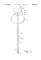
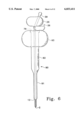
- FIG. 1 is a plan view of a preferred embodiment of the depth guided cannula and stylet according to the present invention
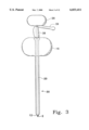
- FIG. 2 is a plan view of another embodiment of a depth guided cannula and stylet according to the present invention.
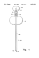
- FIG. 3 is an additional view of the invention shown in FIG. 2, with the cannula in a second preset position with respect to the stylet;
- FIG. 4 is yet another view of the embodiment shown in FIGS. 2-3, with the instruments having been rotated about their longitudinal axes by about ninety degrees;
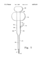
- FIG. 5 shows another preferred embodiment according to the present invention which employs a pressure reduction feature
- FIG. 6 shows another embodiment according to the present invention which employs a pressure reduction feature
- FIG. 7 shows a variant of a connector placement according to the present invention
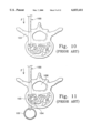
- FIGS. 8, 9, 10 and 11 are progressive views illustrating one of the more serious risks involved in a prior art procedure.
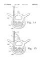
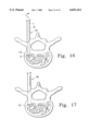
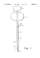
- FIGS. 12, 13, 14, 15, 16 and 17 illustrate some of the advantages and risk reduction that are inherent in using the present invention.
- the present invention substantially reduces several of the risk factors associated with the performance of percutaneous vertebroplasty. Additionally, the present invention enables a reduction in the amount of pressure which must necessarily be applied to the cannula, as well as the "filler" to be implanted via the cannula.
- the general procedure for performing percutaneous vertebroplasty involves the use of a standard 11 gauge Jamshidi needle, illustrated as reference numeral 100 in the prior art illustration of FIGS. 8-11.
- the needle 100 includes an 11 gauge cannula 101 with an internal stylet 102.
- the cannula 101 and stylet 102 are used in conjunction to pierce the cutaneous layers of a patient above the hard tissue to be supplemented, then to penetrate the hard cortical bone 103 of the vertebra, and finally to traverse into the softer cancellous bone 104 underlying the cortical bone.
- a large force F must be applied by the user, axially through the Jamshidi needle to drive the stylet 102 through the cortical bone 103.
- additional downward axial force is required to position the stylet/tip of the cannula into the required position within the cancellous bone, as shown in a progression from FIG. 9 to FIG. 10. If the force magnitude is not reduced appropriately, or if very soft bone is encountered, as is often the case with osteoporitic patients, the stylet and cannula can be accidentally and suddenly driven through the cortical bone 103 on the opposite side of the vertebra.
- the stylet and cannula may continue traveling beyond the cortical bone and into the aorta 105, which is a potentially lethal situation.
- Another potential risk, due to the large driving forces required, is that the stylet 102 and cannula 101 could be driven askew and into the spinal cord 106 with the potential to cause permanent paralysis.
- the present invention overcomes these inherent risks by providing instruments, particularly cannulae, which can be driven through the cortical bone much more controllably and reliably. Less force is required to accomplish the placement of the instruments and, at the same time, the advancement of the instruments can be accomplished at a much slower and more controllable, consistent rate, e.g., as sequentially illustrated in FIGS. 12-17.
- a stylet 1 is provided which has a length that is more than sufficient to span the distance from the epidermis of a patient to the cancellous bone tissue in the vertebra, in the preferred configuration.
- the length of the stylet would be about three inches or greater, but lesser lengths may also be employed as well, depending on the size of the patient.
- the length of the stylet can be readily modified without departing from the inventive features of the present invention.
- the stylet 1 is preferably made of a surgical grade of stainless steel, but other known equivalent biocompatible metals and materials may be used for the same purpose. Ideally, the stylet, or at least a distal end thereof, will be radiopaque so that it can be monitored using fluoroscopy, CT or other imaging techniques during the procedure to help determine the depth and location of the penetration.
- a first or distal end of the stylet 1 ends in a point 2 which is sharp and adapted to penetrate hard tissue when axially loaded.
- the stylet 1 includes self-tapping threads 4 extending from the tip 2.
- the self-tapping threads 4 provide an advantage in that once the tip 2 has penetrated the cortical bone (e.g., see FIG. 12), the operator of the stylet can than proceed to advance the stylet by torquing the stylet, which engages the self-tapping threads 4 in the cortical bone 103 and begins to screw the stylet 1 into the cortical bone.
- the stylet could, for example, use non-self tapping threads wherein a pre-tapped hole would be provided in the cortical bone prior to threading the stylet into position.
- the stylet could have no threads whatsoever extending from the tip 2 and still employ the other advantageous features of the present invention.
- the second or proximal end of the stylet preferably has a handle 6 molded or otherwise fixed thereto, to enable the operator to rotate or torque the stylet 1 about its longitudinal axis with a mechanical advantage, and also providing a surface against which to provide a pushing or axial force.
- the handle 6 is preferably molded of polycarbonate.
- the handle could be made from nylon or a host of other well-known plastics suitable for this purpose, or stainless steel, titanium, other biocompatible metals and ceramics.
- a cannula 10 is provided which includes an elongated tubular structure 11 to be positioned in the cancellous bone for delivery of PMMA or other bone implant material therein.
- the tubular structure 11 of the cannula 10 is preferably made of a surgical grade of stainless steel, but may be made of known equivalent materials, similarly to the stylet 1 discussed above.
- at least a distal end of the tubular structure is radiopaque.
- the tubular structure 11 has an inside diameter which is only slightly larger than the outside diameter of the stylet 1, so that the cannula may effortlessly pass axially over the stylet, while at the same time being supported and guided by the stylet.
- a first or distal end 12 of the cannula is preferably (but not necessarily) beveled to ease the penetration of the cannula through the cutaneous and soft tissues, and especially through the hard tissues.
- a second or proximal end of the cannula preferably has a handle 16 molded or otherwise fixed thereto, to enable the operator to rotate, torque or push the cannula 10.
- the handle 16 is preferably molded of polyearbonate. However, any other materials which are durable, sterilizable and biofriendly, as discussed above with regard to handle 6, could be readily substituted.
- the cannula 10 further includes a pawl 14 which extends through the wall of the cannula 11 and which can be ratcheted against a rack of gear teeth 8 provided on the stylet 1.
- the ratchet and pawl arrangement including pawl 14 and gear teeth 8 functions as a driving and control mechanism for the positioning, advancement and control of the cannula 10 with respect to the stylet I and vice versa.
- the pawl 14 can be ratcheted with respect to the rack 8 to move the cannula 10 up or down with respect to the stylet 1.
- the stylet When a stylet is to be threaded or otherwise turned into position for guiding the cannula 10, the stylet may include gear teeth that cicrumscribe the stylet shaft so that the gear teeth are never out of alignment with the pawl 14 on the cannula 10, regardless of the rotational position of the stylet with respect to the cannula.
- the operator After screwing the stylet 1 into the desired position (e.g., the cancellous tissue of the vertebra as shown in FIGS. 12-14) in the hard tissue, as confirmed by viewing the position using an imaging technique referred to above, the operator proceeds to grasp the handle 6 so as to prevent the stylet from rotating further.
- the desired position e.g., the cancellous tissue of the vertebra as shown in FIGS. 12-14
- the operator proceeds to grasp the handle 6 so as to prevent the stylet from rotating further.
- the operator would ratchet the pawl 14 in an up and down fashion to advance the beveled end 12 of the cannula in a direction toward the point of the stylet 2 (FIG. 15).
- the advancement of the cannula 10, and particularly the beveled end 12 are monitored using an imaging technique to ensure the proper placement of the cannula for injection of the PMMA or other hard tissue implant material.
- the beveled end 12 is advanced to a position that is substantially flush with point 2 (FIG. 16)
- the operator will cease the advancement of the cannula 10, since it will have reached its optimal position.
- the stylet 1 Upon disengaging the pawl 14 from the rack 8, the stylet 1 can then be reverse rotated out of the bone and then slid out from its position within the cannula 10, while maintaining the cannula 10 in its position, as shown in FIG. 17.
- An alternative method of inserting the cannula 10 would be to incrementally insert the stylet 1 and the cannula 10. More specifically, the operator would advance the stylet 1 only partially into the cortical bone 103 of the pedicle, and then advance the cannula 10 so as to be substantially flush or close to the tip 2, by ratcheting as described above. Then the operator would again advance the stylet 1 for a small distance through the cortical bone, stop the advancement and follow with advancement of the cannula 10 by the same increment. This type of incremental advancement could be continued until the tip 2 and the beveled end reach the same desired location as described above and shown in FIG. 16.
- Incremental advancement may still further reduce the force that is necessary to be applied to advance the cannula 10 through the cortical bone 103.
- the incremental approach is more time consuming, which is a factor that must be considered in deciding whether or not to use the incremental approach.
- connector 18 Surrounding the second end of the tubular structure 11 is a connector 18 for linking the cannula 10 with a syringe or other tubular supply, for supplying the PMMA or other implantable material that is to be injected via tubular structure 11.
- connector 18 is a Luer-lock type of connector, but other known connecting mechanisms may be successfully interchanged, e.g., a conventional threaded hole, a threads and locking nut arrangement, etc.
- FIG. 2 illustrates an alternative embodiment of a stylet 20 and cannula 30 for uses similar to those described with the embodiment shown in FIG. 1.
- Stylet 20 includes a tip 2 and preferably, but not necessarily, self-tapping threads 4, just as in the embodiment of FIG. 1.
- the materials employed to make the devices in FIG. 2 are the same as those discussed above with regard to like parts in FIG. 1.
- the second or proximal end of the stylet 20 has a handle 26 molded, threaded or otherwise fixed thereto, to enable the operator to torque the stylet about its longitudinal axis with a force applied through a mechanical advantage, and to enable the operator to apply axial force to the stylet.
- Cannula 30 is provided and includes an elongated tubular structure 31 for positioning in the cancellous bone for delivery of PMMA or other bone implant material therein.
- the tubular structure 31 has an inside diameter which is only slightly larger than the outside diameter of the stylet 20, so that the cannula may effortlessly pass axially over the stylet, while at the same time being supported and guided by the stylet.
- a first or distal end 12 of the cannula is preferably (but not necessarily) beveled to ease the penetration of the cannula through the cutaneous and soft tissues, and especially through the hard tissues.
- a second or proximal end of the cannula preferably has a handle 16 molded, threaded or otherwise fixed thereto, to enable the operator to rotate, torque or push the cannula 30.
- a driving mechanism 36 is pivotally mounted to the stylet 20 va pin 37. At least one cam lobe 38 is positioned between handles 26 and 16 for application of force to handle 16 upon actuation. As shown in FIG. 4, the driving mechanism preferably includes a pair of cam lobes located on opposite sides of the stylet shaft. Handle 26 is provided with a slot 35 which receives lever 39 therein. Lever 39 is rotatable about the pivot 37 to apply a rotational force to cam mechanism 38. Upon rotation of lever 39 from the position shown in FIG. 2 to the position shown in FIG. 3, the camming surface of cam mechanism 38 provides a driving force to drive cannula 20 from a first position shown in FIG. 2 to a second position shown in FIG. 3, where the end 12 of the cannula is substantially flush with the tip 2 of the stylet.
- both the embodiments of FIGS. 1 and 2 can be configured so that, when using a stylet having end threads, self-tapping or otherwise, the selftapping may be covered to enables the stylet and cannula to be pushed through the soft tissues of the patient with less drag and less damage to the soft tissues of the patient than would result if the tapping threads were exposed during this part of the procedure e.g., see the configuration shown in FIG. 3.
- the operator can then retract the cannula 10, 30 from the tip 2 to expose the threads 4 to be threaded into the bone.
- retraction of the embodiment in FIG. 2 is much faster than that of FIG. 1, requiring only a simple rotation of handle 39 as compared to a significant amount of ratcheting of the pawl 14.
- the stylet is configured to be passed through the cortical bone and into the desired position, either by the use of self-tapping threads 4 or other means discussed above, including simply piercing an unthreaded stylet through the cortical bone.
- handle 26 is next torqued in a clockwise direction to engage the self-tapping threads 4 in the cortical bone and begin screwing the stylet 1, 20 through the cortical bone and into the desired position in the cancellous bone.
- the operator After screwing the stylet 1, 20 into the desired position (e.g., the cancellous tissue of the vertebra) in the hard tissue, as confirmed by viewing the position using an imaging technique referred to above, the operator proceeds to move the cannula 10, 30 into position in the manners already described.
- desired position e.g., the cancellous tissue of the vertebra
- FIGS. 1 and 2 would still provide substantially the same factors of safety for advancement of the respective cannulae disclosed therein.
- an alternative method of inserting the cannula 30 would be to incrementally insert the stylet 20 and the cannula 30. More specifically, the operator could thread or otherwise insert the stylet 20 only partially into the cortical bone 103 of the pedicle, and then advance the cannula 30 so as to be substantially flush or close to the tip 2 as described above. Then the operator would release the camming surface 38 to position lever 39 as shown in FIG. 2, and then again advance the stylet for a small distance through the cortical bone, stop the advancement and follow with advancement of the cannula 30 by the same increment. This type of incremental advancement could be continued until the tip 2 and the beveled end reach the same desired location as described above.
- Incremental advancement may still further reduce the force that is necessary to be applied to advance the cannula 30 through the cortical bone 103 and thereby increase the safety factor during insertion of the cannula 30.
- the incremental approach is more time consuming, which is a factor that must be considered in deciding whether or not to use the incremental approach.
- a connector 18 Surrounding the second end of the tubular structure 31 is a connector 18 for linking the cannula 30 with a syringe or other tubular supply, for supplying the PMMA or other implantable material that is to be injected via the tubular structure 31.
- FIG. 5 shows a variant of the embodiment described with regard to FIG. 1.
- FIG. 5 shows a modification in which the cannula 70 includes a modified tubular structure design.
- the first or distal portion 71 of the tubular structure is of the same dimensions as the embodiment of FIG. 1.
- the second or proximal portion 72 of the cannula 70 has a substantially larger diameter than that of the first portion 71.
- the diameter of second portion 72 is about twice the diameter of first portion 71, although any increase in the diameter of second portion 72 over that of the first portion 71 will decrease the pressure requirement for effective delivery of the material to be implanted.
- the first and second portions 71, 72 have approximately equal lengths, but this is governed by the anatomy of the site to be accessed. In the "average" percutaneous vertebroplasty situation, the first portion 71 is required to be about 1.5" long, as this is the length that is needed for traversing the cortical bone of the pedicle. Thus, the first portion should not be significantly enlarged due to the size constraints of the pedicle, the safety risks to the spinal column and aorta which are increased when the cannula size is increased intravertebrally, and by the desire to remove as little bone as possible when entering with the stylet and cannula, among other factors.
- the portion of the cannula which will occupy the soft tissues can be significantly expanded without substantially adversely effecting the patient. Given the benefits of reducing the required injection pressure and ensuring a better delivery of the bone implant material, such a modification becomes a viable option.
- a pawl 14 passes through a wall of the cannula 70, preferably in the second portion 72.
- the pawl 14 can be ratcheted against a rack of gear teeth 8 provided on the stylet 60.
- the ratchet and pawl arrangement including pawl 14 and gear teeth 8 functions as a driving and control mechanism for the positioning, advancement and control of the cannula 70 with respect to the stylet 60 and vice versa.
- the pawl 14 can be ratcheted with respect to the rack 8 to move the cannula 70 up or down with respect to the stylet 60.
- the stylet may include gear teeth that cicrumscribe the stylet shaft so that the gear teeth are never out of alignment with the pawl 14 on the cannula 10, regardless of the rotational position of the stylet with respect to the cannula.
- the stylet 60 is designed to closely follow the contour of the cannula 70 to provide a close guidance along the full length of the cannula 70. While the first portion 61 is substantially of the same diameter as the stylet 1 in FIG. 1, the second portion 62 must be substantially larger, preferably twice the diameter of the first portion, to follow the contours of the portion 72 of the cannula.
- a stylet having only a single diameter throughout e.g., a diameter equal to that of portion 61 could be employed.
- Such an embodiment would require modification of the pawl 14 to extend further radially inward so as to interact with gear teeth that would be placed on a smaller diameter stylet.
- the ratcheting of the pawl against gear teeth 8 provides a driving and control mechanism for the positioning, advancement and control of the cannula 70 with respect to the stylet 60 and vice versa.
- Handle 76 is substantially similar to handle 16 in its design, material, and connection with the tubular structure 71. However, due to the increased diameter of the second portion 72 of the tubular structure 70 and the second portion 62 of the stylet 60, the handle 76 must also have an increased hole through which the second portion 62 of the stylet 60 passes.
- Handle 66 is substantially similar to handle 6 in its design, material, and connection with the stylet 60, although if molded around the stylet 60, the handle 66 must also have a larger hole than handle 6 to pass the enlarge diameter of the stylet portion 62.
- connector 78 Surrounding the second end of the tubular structure of the cannula 70 is a connector 78 for linking the cannula 70 with a syringe or other tubular supply, for supplying the PMMA or other implantable material that is to be injected via the cannula 70.
- connector 78 is a Luer-lock type of connector, but other known connecting mechanisms may be successfully interchanged, e.g., a conventional threaded hole, a threads and locking nut arrangement, etc.
- the variant shown in FIG. 6 combines the advantages of the embodiment shown in FIGS. 2-4 with the pressure reducing concept described above with respect to FIG. 5.
- the variant shown in FIG. 6 uses the same stylet 20 as that shown in FIG. 2, but has a cannula 90 which includes a modified tubular structure design. However, a stylet that generally follows the contours of cannula 90 could alternatively be used.
- the first or distal portion 91 of the tubular structure is of the same dimensions as the cannula 30.
- the second or proximal portion 92 of the cannula 90 has a substantially larger diameter than that of the first portion 91, similar to the cannula in FIG. 5.
- the diameter of second portion 92 is about twice the diameter of first portion 91, although any increase in the diameter of second portion 92 over that of the first portion 91 will decrease the pressure requirement for effective delivery of the material to be implanted.
- the devices shown in FIG. 6 operate similarly to that of the embodiment of FIGS. 2-5 with the added advantage of reduction of the pressure required to deliver the implant material.
- Handle 93 is substantially similar to handle 16 in its design, material, and connection with the tubular structure 92. However, due to the increased diameter of the second portion 92 of the tubular structure 90, the handle 93 must also have an increased hole through which the second portion 92 of the cannula 90 passes.
- connector 78 Surrounding the second end of the tubular structure of the cannula 90 is a connector 78 for linking the cannula 90 with a syringe or other tubular supply, for supplying the PMMA or other implantable material that is to be injected via the cannula 90.
- connector 78 is a Luer-lock type of connector, but other known connecting mechanisms may be successfully interchanged, e.g., a conventional threaded hole, a threads and locking nut arrangement, etc.
- the driving control mechanism functions essentially the same as that described above with regard to FIGS. 2-4.
- FIG. 7 shows a variation in the placement of a connector 18' for linking the cannula 10' with a syringe or other tubular supply, for supplying the PMMA or other implantable material that is to be injected via tubular structure 11'.
- This variation can also be employed with any of the earlier described cannula embodiments.
- connector 18' is a Luer-lock type of connector, but other known connecting mechanisms may be successfully interchanged, e.g., a conventional threaded hole, a threads and locking nut arrangement, etc.
- the connector 18' is provided on the surface of handle 16' at a position out of line with the longitudinal axis 11 of the cannula 11'.
- an additional bore 19 is provided in handle 16' to join the connector 18' with the internal bore of the cannula 10'such that longitudinal axis 19' of bore 19 is non-parallel with and intersects longitudinal axis 11" of cannula 11' at imaginary intersection point 1911.
- the connector 18' may be positioned at any convenient angle to the longitudinal axis of the cannula 11' and located at any convenient location on the surface of handle 16'. This variation enables pressure to be applied, and even the beginning of injection of the implant material, while the stylet 1 is still at least partially inserted within the cannula 11'.
- a seal 21 (e.g., an o-ring or equivalent) may be provided to help maintain a pressure seal between the stylet 1 and the handle 16' in the event that the stylet 1 is still within the handle 16' when injection begins. Additionally or alternatively, threads 21' may be provided in handle 16' to accept a plug to positively seal the handle 16' during injection.
Abstract
Description
Claims (15)
Priority Applications (3)
| Application Number | Priority Date | Filing Date | Title |
|---|---|---|---|
| US08/949,839 US6033411A (en) | 1997-10-14 | 1997-10-14 | Precision depth guided instruments for use in vertebroplasty |
| PCT/US1998/021662 WO1999018866A1 (en) | 1997-10-14 | 1998-10-14 | Precision instruments for use in vertebroplasty |
| AU10844/99A AU1084499A (en) | 1997-10-14 | 1998-10-14 | Precision instruments for use in vertebroplasty |
Applications Claiming Priority (1)
| Application Number | Priority Date | Filing Date | Title |
|---|---|---|---|
| US08/949,839 US6033411A (en) | 1997-10-14 | 1997-10-14 | Precision depth guided instruments for use in vertebroplasty |
Publications (1)
| Publication Number | Publication Date |
|---|---|
| US6033411A true US6033411A (en) | 2000-03-07 |
Family
ID=25489586
Family Applications (1)
| Application Number | Title | Priority Date | Filing Date |
|---|---|---|---|
| US08/949,839 Expired - Lifetime US6033411A (en) | 1997-10-14 | 1997-10-14 | Precision depth guided instruments for use in vertebroplasty |
Country Status (3)
| Country | Link |
|---|---|
| US (1) | US6033411A (en) |
| AU (1) | AU1084499A (en) |
| WO (1) | WO1999018866A1 (en) |
Cited By (150)
| Publication number | Priority date | Publication date | Assignee | Title |
|---|---|---|---|---|
| US6375659B1 (en) | 2001-02-20 | 2002-04-23 | Vita Licensing, Inc. | Method for delivery of biocompatible material |
| US6450973B1 (en) * | 2000-06-16 | 2002-09-17 | Kieran P. J. Murphy | Biopsy gun |
| US6488667B1 (en) | 2000-06-15 | 2002-12-03 | Kieran P. J. Murphy | Needle control device |
| US20030032964A1 (en) * | 2001-02-15 | 2003-02-13 | Neil Watkins | Vertebroplasty bone cement |
| US20030078589A1 (en) * | 1998-04-01 | 2003-04-24 | Preissman Howard E. | High pressure applicator |
| US6595998B2 (en) | 2001-03-08 | 2003-07-22 | Spinewave, Inc. | Tissue distraction device |
| US6613018B2 (en) | 2001-02-20 | 2003-09-02 | Vita Licensing, Inc. | System and kit for delivery of restorative materials |
| US20030225411A1 (en) * | 2002-05-31 | 2003-12-04 | Vidacare Corporation | Apparatus and method to access bone marrow |
| US20040073139A1 (en) * | 2002-10-11 | 2004-04-15 | Hirsch Joshua A. | Cannula for extracting and implanting material |
| US20040092946A1 (en) * | 2001-02-20 | 2004-05-13 | Bagga Charanpreet S. | System and kit for delivery of restorative materials |
| US20040095844A1 (en) * | 2001-02-26 | 2004-05-20 | Miller Scott H. | Enclosed implantable material mixing system |
| US6752791B2 (en) | 2000-06-15 | 2004-06-22 | Cook Incorporated | Needle control device |
| US20040126557A1 (en) * | 2000-12-07 | 2004-07-01 | Lothar Thiele | Stone composite slabs |
| US20040162559A1 (en) * | 2003-02-14 | 2004-08-19 | Arramon Yves P. | Bone access system |
| US6783515B1 (en) * | 1999-09-30 | 2004-08-31 | Arthrocare Corporation | High pressure delivery system |
| US6793660B2 (en) | 2001-08-20 | 2004-09-21 | Synthes (U.S.A.) | Threaded syringe for delivery of a bone substitute material |
| US20040193171A1 (en) * | 2003-03-31 | 2004-09-30 | Depuy Acromed, Inc. | Remotely-activated vertebroplasty injection device |
| US20040267269A1 (en) * | 2001-06-01 | 2004-12-30 | Middleton Lance M. | Tissue cavitation device and method |
| US20050070915A1 (en) * | 2003-09-26 | 2005-03-31 | Depuy Spine, Inc. | Device for delivering viscous material |
| US20050113843A1 (en) * | 2003-11-25 | 2005-05-26 | Arramon Yves P. | Remotely actuated system for bone cement delivery |
| US20050131345A1 (en) * | 2002-05-31 | 2005-06-16 | Larry Miller | Apparatus and method for accessing the bone marrow of the sternum |
| US20050148940A1 (en) * | 2002-05-31 | 2005-07-07 | Larry Miller | Apparatus and method for accessing the bone marrow |
| US20050165403A1 (en) * | 2004-01-26 | 2005-07-28 | Miller Larry J. | Impact-driven intraosseous needle |
| US20050222538A1 (en) * | 2004-03-30 | 2005-10-06 | Sdgi Holdings, Inc. | Surgical system for delivery of viscous fluids |
| US20050261693A1 (en) * | 2002-05-31 | 2005-11-24 | Miller Larry J | Apparatus and method to inject fluids into bone marrow and other target sites |
| US20050267383A1 (en) * | 2002-10-22 | 2005-12-01 | Groenke Gregory C | Biopsy device handle assembly |
| US20050277845A1 (en) * | 2004-05-27 | 2005-12-15 | David Cooke | Medical instrument |
| US20060058807A1 (en) * | 2004-08-25 | 2006-03-16 | Michael Landry | Expandable interbody fusion device |
| US20060064101A1 (en) * | 2004-02-12 | 2006-03-23 | Arthrocare Corporation | Bone access system |
| KR100568071B1 (en) * | 2003-12-16 | 2006-04-05 | 주식회사 경원메디칼 | An injection apparatus of bone cement for treatment of osteoporotic bone |
| US20060100547A1 (en) * | 2004-10-27 | 2006-05-11 | Omnisonics Medical Technologies, Inc. | Apparatus and method for using an ultrasonic medical device to reinforce bone |
| US20060116604A1 (en) * | 2002-11-20 | 2006-06-01 | Adams Leland R | Medical instrument |
| US20060142779A1 (en) * | 2004-12-23 | 2006-06-29 | Arthrocare Corporation | Cannula having asymmetrically-shaped threads |
| US20060155296A1 (en) * | 2005-01-07 | 2006-07-13 | Celonova Biosciences, Inc. | Three-dimensional implantable bone support |
| US20060164913A1 (en) * | 2005-01-21 | 2006-07-27 | Arthrocare Corporation | Multi-chamber integrated mixing and delivery system |
| US20060229629A1 (en) * | 2003-05-16 | 2006-10-12 | Spine Wave, Inc. | Tissue distraction device |
| US20070016100A1 (en) * | 2002-05-31 | 2007-01-18 | Miller Larry J | Apparatus and Methods to Harvest Bone and Bone Marrow |
| US20070049945A1 (en) * | 2002-05-31 | 2007-03-01 | Miller Larry J | Apparatus and methods to install, support and/or monitor performance of intraosseous devices |
| WO2007024641A3 (en) * | 2005-08-22 | 2007-05-03 | Kieran P Murphy | Bone augmentation apparatus |
| US20070123877A1 (en) * | 2005-11-15 | 2007-05-31 | Aoi Medical, Inc. | Inflatable Device for Restoring Anatomy of Fractured Bone |
| US20070173826A1 (en) * | 2006-01-20 | 2007-07-26 | Alpha Orthopaedics | Intramedullar devices and methods to reduce and/or fix damaged bone |
| US20070191836A1 (en) * | 2006-01-27 | 2007-08-16 | Sdgi Holdings, Inc. | Methods and devices for a minimally invasive placement of a rod within a patient |
| US20070225573A1 (en) * | 2006-03-27 | 2007-09-27 | Ethicon Endo-Surgery, Inc. | Methods and devices for percutaneous illumination |
| US20070243657A1 (en) * | 2006-04-13 | 2007-10-18 | Basol Bulent M | Method and Apparatus to Form Thin Layers of Materials on a Base |
| US20070260184A1 (en) * | 2006-05-04 | 2007-11-08 | Sdgi Holdings, Inc. | Retractable stylet and cannula combination |
| US20070260258A1 (en) * | 2006-05-05 | 2007-11-08 | Robert Sommerich | Access and delivery needle for percutaneous vertebroplasty |
| US20070260255A1 (en) * | 2006-05-04 | 2007-11-08 | Sdgi Holdings, Inc. | Method for using retractable stylet and cannula combination to form an opening in bone |
| US20070270775A1 (en) * | 2004-11-12 | 2007-11-22 | Miller Larry J | Intraosseous Device And Methods For Accessing Bone Marrow In The Sternum And Other Target Areas |
| US20080021463A1 (en) * | 2006-07-21 | 2008-01-24 | Bassem Georgy | Device and method for introducing flowable material into a body cavity |
| US20080045965A1 (en) * | 2002-05-31 | 2008-02-21 | Miller Larry J | Apparatus and Methods for Biopsy and Aspiration of Bone Marrow |
| US7371241B2 (en) | 2001-02-12 | 2008-05-13 | Modmed Therapeutics, Inc. | Multi-use surgical cement dispenser apparatus and kit for same |
| US20080114364A1 (en) * | 2006-11-15 | 2008-05-15 | Aoi Medical, Inc. | Tissue cavitation device and method |
| US20080119821A1 (en) * | 2006-11-17 | 2008-05-22 | Warsaw Orthopedic, Inc. | Multiport Cannula |
| US20080125784A1 (en) * | 2006-11-10 | 2008-05-29 | Illuminoss Medical, Inc. | Systems and methods for internal bone fixation |
| US20080154304A1 (en) * | 2006-12-21 | 2008-06-26 | Arthrocare Corporation | System and method for accessing a tissue structure |
| US20080200916A1 (en) * | 2004-09-10 | 2008-08-21 | Murphy Kieran P J | Cement Delivery Needle |
| US20080215056A1 (en) * | 2002-05-31 | 2008-09-04 | Miller Larry J | Powered Drivers, Intraosseous Devices And Methods To Access Bone Marrow |
| US20080269638A1 (en) * | 2002-11-20 | 2008-10-30 | Boston Scientific Scimed, Inc. | Medical Instrument |
| US20080287825A1 (en) * | 2007-05-14 | 2008-11-20 | Boston Scientific Scimed, Inc. | Biopsy Device |
| WO2008140519A1 (en) | 2007-05-10 | 2008-11-20 | Depuy Spine, Inc. | Improved access delivery needle for percutaneous vertebroplasty |
| US20080294167A1 (en) * | 2007-05-21 | 2008-11-27 | Brian Schumacher | Articulating cavitation device |
| US20080300598A1 (en) * | 2007-05-31 | 2008-12-04 | Spine Wave, Inc. | Expandable Interbody Fusion Device |
| US20090054900A1 (en) * | 2006-11-10 | 2009-02-26 | Illuminoss Medical, Inc. | Systems and Methods for Internal Bone Fixation |
| US20090105711A1 (en) * | 2007-10-19 | 2009-04-23 | David Mitchell | Cannula with lateral access and directional exit port |
| US20090112196A1 (en) * | 2007-10-31 | 2009-04-30 | Illuminoss Medical, Inc. | Light Source |
| US20090164016A1 (en) * | 2007-12-19 | 2009-06-25 | Bassem Georgy | Device and method for orthopedic fracture fixation |
| US20090270761A1 (en) * | 2002-11-20 | 2009-10-29 | Boston Scientific Scimed, Inc. | Medical Instrument |
| US20100023065A1 (en) * | 2008-07-25 | 2010-01-28 | Welch Andrea M | Tissue access device with alignment guide and methods of use |
| US20100049230A1 (en) * | 2002-11-14 | 2010-02-25 | Brainsgate Ltd. | Greater palatine canal stylet |
| US20100065919A1 (en) * | 2006-09-28 | 2010-03-18 | Seo-Woo Nam | Semiconductor Devices Including Multiple Stress Films in Interface Area |
| US20100114184A1 (en) * | 2008-10-07 | 2010-05-06 | Brainsgate Ltd. | Flexible tools for preparing bony canals |
| US7794414B2 (en) | 2004-02-09 | 2010-09-14 | Emigrant Bank, N.A. | Apparatus and method for an ultrasonic medical device operating in torsional and transverse modes |
| US7806900B2 (en) | 2006-04-26 | 2010-10-05 | Illuminoss Medical, Inc. | Apparatus and methods for delivery of reinforcing materials to bone |
| US20100256641A1 (en) * | 2007-12-26 | 2010-10-07 | Illuminoss Medical, Inc. | Apparatus and Methods for Repairing Craniomaxillofacial Bones Using Customized Bone Plates |
| US7811290B2 (en) | 2006-04-26 | 2010-10-12 | Illuminoss Medical, Inc. | Apparatus and methods for reinforcing bone |
| US20100262069A1 (en) * | 2009-04-07 | 2010-10-14 | Illuminoss Medical, Inc. | Photodynamic Bone Stabilization Systems and Methods for Reinforcing Bone |
| US20100265733A1 (en) * | 2009-04-06 | 2010-10-21 | Illuminoss Medical, Inc. | Attachment System for Light-Conducting Fibers |
| US20100298784A1 (en) * | 2004-01-26 | 2010-11-25 | Miller Larry J | Manual Intraosseous Device |
| US20110118740A1 (en) * | 2009-11-10 | 2011-05-19 | Illuminoss Medical, Inc. | Intramedullary Implants Having Variable Fastener Placement |
| KR101040516B1 (en) | 2009-05-14 | 2011-06-16 | 주식회사 위노바 | Instrument for Insertion of Working Sleeve for Spinal Surgery |
| US20110190776A1 (en) * | 2009-12-18 | 2011-08-04 | Palmaz Scientific, Inc. | Interosteal and intramedullary implants and method of implanting same |
| US8142462B2 (en) | 2004-05-28 | 2012-03-27 | Cavitech, Llc | Instruments and methods for reducing and stabilizing bone fractures |
| US20120109111A1 (en) * | 2010-10-29 | 2012-05-03 | Empire Technology Development Llc | Fenestration system |
| US8221420B2 (en) | 2009-02-16 | 2012-07-17 | Aoi Medical, Inc. | Trauma nail accumulator |
| US20120239047A1 (en) * | 2009-11-10 | 2012-09-20 | Linderman Evan D | Apparatus and method for stylet-guided vertebral augmentation |
| US8361078B2 (en) | 2003-06-17 | 2013-01-29 | Depuy Spine, Inc. | Methods, materials and apparatus for treating bone and other tissue |
| US8360629B2 (en) | 2005-11-22 | 2013-01-29 | Depuy Spine, Inc. | Mixing apparatus having central and planetary mixing elements |
| US8415407B2 (en) | 2004-03-21 | 2013-04-09 | Depuy Spine, Inc. | Methods, materials, and apparatus for treating bone and other tissue |
| US20130150752A1 (en) * | 2011-12-12 | 2013-06-13 | Karl W. Swann | Apparatus for Bone Aspiration |
| US8641715B2 (en) | 2002-05-31 | 2014-02-04 | Vidacare Corporation | Manual intraosseous device |
| US20140039400A1 (en) * | 2007-12-07 | 2014-02-06 | Pyng Medical Corp. | Apparatus and methods for introducing portals in bone |
| US8656929B2 (en) | 2002-05-31 | 2014-02-25 | Vidacare Corporation | Medical procedures trays and related methods |
| US8684965B2 (en) | 2010-06-21 | 2014-04-01 | Illuminoss Medical, Inc. | Photodynamic bone stabilization and drug delivery systems |
| US8690791B2 (en) | 2002-05-31 | 2014-04-08 | Vidacare Corporation | Apparatus and method to access the bone marrow |
| US8715351B1 (en) | 2012-11-29 | 2014-05-06 | Spine Wave, Inc. | Expandable interbody fusion device with graft chambers |
| US8758383B2 (en) | 2011-03-01 | 2014-06-24 | Safe Wire Holding, Llc | Depth controlled Jamshidi needle |
| US8790359B2 (en) | 1999-10-05 | 2014-07-29 | Cybersonics, Inc. | Medical systems and related methods |
| US8828019B1 (en) | 2013-03-13 | 2014-09-09 | Spine Wave, Inc. | Inserter for expanding an expandable interbody fusion device |
| US8870965B2 (en) | 2009-08-19 | 2014-10-28 | Illuminoss Medical, Inc. | Devices and methods for bone alignment, stabilization and distraction |
| US8900312B2 (en) | 2013-03-12 | 2014-12-02 | Spine Wave, Inc. | Expandable interbody fusion device with graft chambers |
| US8936644B2 (en) | 2011-07-19 | 2015-01-20 | Illuminoss Medical, Inc. | Systems and methods for joint stabilization |
| US8939977B2 (en) | 2012-07-10 | 2015-01-27 | Illuminoss Medical, Inc. | Systems and methods for separating bone fixation devices from introducer |
| US8944069B2 (en) | 2006-09-12 | 2015-02-03 | Vidacare Corporation | Assemblies for coupling intraosseous (IO) devices to powered drivers |
| US8950929B2 (en) | 2006-10-19 | 2015-02-10 | DePuy Synthes Products, LLC | Fluid delivery system |
| US8974410B2 (en) | 2006-10-30 | 2015-03-10 | Vidacare LLC | Apparatus and methods to communicate fluids and/or support intraosseous devices |
| US8986307B2 (en) | 2012-07-10 | 2015-03-24 | X-Spine Systems, Inc. | Surgical instrument with pivotable implant holder |
| US8992522B2 (en) | 2002-09-30 | 2015-03-31 | Relievant Medsystems, Inc. | Back pain treatment methods |
| US8992541B2 (en) | 2003-03-14 | 2015-03-31 | DePuy Synthes Products, LLC | Hydraulic device for the injection of bone cement in percutaneous vertebroplasty |
| US9017325B2 (en) | 2002-09-30 | 2015-04-28 | Relievant Medsystems, Inc. | Nerve modulation systems |
| US9039701B2 (en) | 2008-09-26 | 2015-05-26 | Relievant Medsystems, Inc. | Channeling paths into bone |
| US9072543B2 (en) | 2002-05-31 | 2015-07-07 | Vidacare LLC | Vascular access kits and methods |
| US9078767B1 (en) | 2014-03-06 | 2015-07-14 | Spine Wave, Inc. | Expandable spinal interbody fusion device |
| US9119639B2 (en) | 2011-08-09 | 2015-09-01 | DePuy Synthes Products, Inc. | Articulated cavity creator |
| US9144442B2 (en) | 2011-07-19 | 2015-09-29 | Illuminoss Medical, Inc. | Photodynamic articular joint implants and methods of use |
| US9179959B2 (en) | 2010-12-22 | 2015-11-10 | Illuminoss Medical, Inc. | Systems and methods for treating conditions and diseases of the spine |
| US9241729B2 (en) | 2012-12-14 | 2016-01-26 | DePuy Synthes Products, Inc. | Device to aid in the deployment of a shape memory instrument |
| US9265623B2 (en) | 2014-03-06 | 2016-02-23 | Spine Wave, Inc. | Method of expanding a spinal interbody fusion device |
| US9265522B2 (en) | 2008-09-26 | 2016-02-23 | Relievant Medsystems, Inc. | Methods for navigating an instrument through bone |
| US9381024B2 (en) | 2005-07-31 | 2016-07-05 | DePuy Synthes Products, Inc. | Marked tools |
| US9439783B2 (en) | 2014-03-06 | 2016-09-13 | Spine Wave, Inc. | Inserter for expanding body tissue |
| US9439693B2 (en) | 2013-02-01 | 2016-09-13 | DePuy Synthes Products, Inc. | Steerable needle assembly for use in vertebral body augmentation |
| US9445921B2 (en) | 2014-03-06 | 2016-09-20 | Spine Wave, Inc. | Device for expanding and supporting body tissue |
| US9504477B2 (en) | 2003-05-30 | 2016-11-29 | Vidacare LLC | Powered driver |
| US9510910B2 (en) | 2006-09-12 | 2016-12-06 | Vidacare LLC | Medical procedures trays and related methods |
| USRE46356E1 (en) | 2002-09-30 | 2017-04-04 | Relievant Medsystems, Inc. | Method of treating an intraosseous nerve |
| US9642932B2 (en) | 2006-09-14 | 2017-05-09 | DePuy Synthes Products, Inc. | Bone cement and methods of use thereof |
| US9675796B2 (en) | 2013-11-10 | 2017-06-13 | Brainsgate Ltd. | Implant and delivery system for neural stimulator |
| US9687281B2 (en) | 2012-12-20 | 2017-06-27 | Illuminoss Medical, Inc. | Distal tip for bone fixation devices |
| US9724151B2 (en) | 2013-08-08 | 2017-08-08 | Relievant Medsystems, Inc. | Modulating nerves within bone using bone fasteners |
| US9724107B2 (en) | 2008-09-26 | 2017-08-08 | Relievant Medsystems, Inc. | Nerve modulation systems |
| US9775627B2 (en) | 2012-11-05 | 2017-10-03 | Relievant Medsystems, Inc. | Systems and methods for creating curved paths through bone and modulating nerves within the bone |
| US9848944B2 (en) | 2002-09-30 | 2017-12-26 | Relievant Medsystems, Inc. | Thermal denervation devices and methods |
| US9918767B2 (en) | 2005-08-01 | 2018-03-20 | DePuy Synthes Products, Inc. | Temperature control system |
| US9925028B1 (en) | 2016-11-15 | 2018-03-27 | Proximate Concepts Llc | Device for the delivery of a prosthetic implant and method of use thereof |
| US9999444B2 (en) | 2011-03-01 | 2018-06-19 | Orthovita, Inc. | Depth controlled Jamshidi needle |
| US10271907B2 (en) | 2015-05-13 | 2019-04-30 | Brainsgate Ltd. | Implant and delivery system for neural stimulator |
| US10314633B2 (en) | 2005-11-18 | 2019-06-11 | Stryker Corporation | Shape memory device with temperature-dependent deflectable segment and methods of positioning a shape memory device within a bone structure |
| US10390877B2 (en) | 2011-12-30 | 2019-08-27 | Relievant Medsystems, Inc. | Systems and methods for treating back pain |
| US10588691B2 (en) | 2012-09-12 | 2020-03-17 | Relievant Medsystems, Inc. | Radiofrequency ablation of tissue within a vertebral body |
| US10695073B2 (en) | 2017-08-22 | 2020-06-30 | Arthrex, Inc. | Control system for retrograde drill medical device |
| US10702336B2 (en) | 2005-09-02 | 2020-07-07 | Madison Surgical Designs, Llc | Surgical devices |
| US10722335B1 (en) | 2016-11-15 | 2020-07-28 | Proximate Concepts Llc | Device for the delivery of a prosthetic implant and method of use thereof |
| US10973532B2 (en) | 2002-05-31 | 2021-04-13 | Teleflex Life Sciences Limited | Powered drivers, intraosseous devices and methods to access bone marrow |
| US10973545B2 (en) | 2002-05-31 | 2021-04-13 | Teleflex Life Sciences Limited | Powered drivers, intraosseous devices and methods to access bone marrow |
| US11007010B2 (en) | 2019-09-12 | 2021-05-18 | Relevant Medsysterns, Inc. | Curved bone access systems |
| US11065132B2 (en) | 2014-03-06 | 2021-07-20 | Spine Wave, Inc. | Method of expanding a space between opposing tissue surfaces |
| US11071572B2 (en) | 2018-06-27 | 2021-07-27 | Illuminoss Medical, Inc. | Systems and methods for bone stabilization and fixation |
| US11202621B2 (en) * | 2017-11-22 | 2021-12-21 | Devicor Medical Products | Adjustable targeting set for MRI guided biopsy procedure |
| US11337728B2 (en) | 2002-05-31 | 2022-05-24 | Teleflex Life Sciences Limited | Powered drivers, intraosseous devices and methods to access bone marrow |
| US11850135B2 (en) | 2019-08-01 | 2023-12-26 | Paul H. Rosenberg Family Trust | Prosthetic implant delivery device utilizing surface active agents |
Families Citing this family (27)
| Publication number | Priority date | Publication date | Assignee | Title |
|---|---|---|---|---|
| US6749595B1 (en) | 2000-06-15 | 2004-06-15 | Kieran P. J. Murphy | Cement delivery needle |
| WO2008033872A2 (en) | 2006-09-12 | 2008-03-20 | Vidacare Corporation | Biopsy devices and related methods |
| US7578819B2 (en) | 2005-05-16 | 2009-08-25 | Baxano, Inc. | Spinal access and neural localization |
| EP1799129B1 (en) | 2004-10-15 | 2020-11-25 | Baxano, Inc. | Devices for tissue removal |
| US20100331883A1 (en) | 2004-10-15 | 2010-12-30 | Schmitz Gregory P | Access and tissue modification systems and methods |
| US9101386B2 (en) | 2004-10-15 | 2015-08-11 | Amendia, Inc. | Devices and methods for treating tissue |
| US7938830B2 (en) | 2004-10-15 | 2011-05-10 | Baxano, Inc. | Powered tissue modification devices and methods |
| US8430881B2 (en) | 2004-10-15 | 2013-04-30 | Baxano, Inc. | Mechanical tissue modification devices and methods |
| US7738969B2 (en) | 2004-10-15 | 2010-06-15 | Baxano, Inc. | Devices and methods for selective surgical removal of tissue |
| US8257356B2 (en) | 2004-10-15 | 2012-09-04 | Baxano, Inc. | Guidewire exchange systems to treat spinal stenosis |
| US20110190772A1 (en) | 2004-10-15 | 2011-08-04 | Vahid Saadat | Powered tissue modification devices and methods |
| US7963915B2 (en) | 2004-10-15 | 2011-06-21 | Baxano, Inc. | Devices and methods for tissue access |
| US8048080B2 (en) | 2004-10-15 | 2011-11-01 | Baxano, Inc. | Flexible tissue rasp |
| US7857813B2 (en) | 2006-08-29 | 2010-12-28 | Baxano, Inc. | Tissue access guidewire system and method |
| US8062300B2 (en) | 2006-05-04 | 2011-11-22 | Baxano, Inc. | Tissue removal with at least partially flexible devices |
| US7887538B2 (en) | 2005-10-15 | 2011-02-15 | Baxano, Inc. | Methods and apparatus for tissue modification |
| US8221397B2 (en) | 2004-10-15 | 2012-07-17 | Baxano, Inc. | Devices and methods for tissue modification |
| US9247952B2 (en) | 2004-10-15 | 2016-02-02 | Amendia, Inc. | Devices and methods for tissue access |
| US8366712B2 (en) | 2005-10-15 | 2013-02-05 | Baxano, Inc. | Multiple pathways for spinal nerve root decompression from a single access point |
| US8062298B2 (en) | 2005-10-15 | 2011-11-22 | Baxano, Inc. | Flexible tissue removal devices and methods |
| US8092456B2 (en) | 2005-10-15 | 2012-01-10 | Baxano, Inc. | Multiple pathways for spinal nerve root decompression from a single access point |
| WO2009032363A1 (en) | 2007-09-06 | 2009-03-12 | Baxano, Inc. | Method, system and apparatus for neural localization |
| US8192436B2 (en) | 2007-12-07 | 2012-06-05 | Baxano, Inc. | Tissue modification devices |
| US9314253B2 (en) | 2008-07-01 | 2016-04-19 | Amendia, Inc. | Tissue modification devices and methods |
| EP2328489B1 (en) | 2008-07-14 | 2019-10-09 | Amendia, Inc. | Tissue modification devices |
| US9220554B2 (en) | 2010-02-18 | 2015-12-29 | Globus Medical, Inc. | Methods and apparatus for treating vertebral fractures |
| US10980568B1 (en) | 2019-11-25 | 2021-04-20 | Izi Medical Products, Llc | Half handle bone access needle |
Citations (10)
| Publication number | Priority date | Publication date | Assignee | Title |
|---|---|---|---|---|
| US4469109A (en) * | 1981-12-24 | 1984-09-04 | Creative Research And Manufacturing Inc. | Bone marrow aspiration needle |
| US4670008A (en) * | 1985-07-01 | 1987-06-02 | Albertini Beat | High flux threaded needle |
| US4793363A (en) * | 1986-09-11 | 1988-12-27 | Sherwood Medical Company | Biopsy needle |
| US5014717A (en) * | 1989-02-10 | 1991-05-14 | Lohrmann Guenter | Punch-biopsy apparatus with cannula-aiming device |
| US5195526A (en) * | 1988-03-11 | 1993-03-23 | Michelson Gary K | Spinal marker needle |
| US5372583A (en) * | 1992-11-25 | 1994-12-13 | Cardiopulmonary Specialities, Inc. | Bone marrow infuser and method of use |
| US5456267A (en) * | 1994-03-18 | 1995-10-10 | Stark; John G. | Bone marrow harvesting systems and methods and bone biopsy systems and methods |
| US5458579A (en) * | 1991-12-31 | 1995-10-17 | Technalytics, Inc. | Mechanical trocar insertion apparatus |
| DE4413520A1 (en) * | 1994-04-19 | 1995-10-26 | Ruesch Willy Ag | Device for the controlled placement of a trocar or a puncture cannula |
| US5660186A (en) * | 1995-06-07 | 1997-08-26 | Marshfield Clinic | Spiral biopsy stylet |
-
1997
- 1997-10-14 US US08/949,839 patent/US6033411A/en not_active Expired - Lifetime
-
1998
- 1998-10-14 WO PCT/US1998/021662 patent/WO1999018866A1/en active Application Filing
- 1998-10-14 AU AU10844/99A patent/AU1084499A/en not_active Abandoned
Patent Citations (10)
| Publication number | Priority date | Publication date | Assignee | Title |
|---|---|---|---|---|
| US4469109A (en) * | 1981-12-24 | 1984-09-04 | Creative Research And Manufacturing Inc. | Bone marrow aspiration needle |
| US4670008A (en) * | 1985-07-01 | 1987-06-02 | Albertini Beat | High flux threaded needle |
| US4793363A (en) * | 1986-09-11 | 1988-12-27 | Sherwood Medical Company | Biopsy needle |
| US5195526A (en) * | 1988-03-11 | 1993-03-23 | Michelson Gary K | Spinal marker needle |
| US5014717A (en) * | 1989-02-10 | 1991-05-14 | Lohrmann Guenter | Punch-biopsy apparatus with cannula-aiming device |
| US5458579A (en) * | 1991-12-31 | 1995-10-17 | Technalytics, Inc. | Mechanical trocar insertion apparatus |
| US5372583A (en) * | 1992-11-25 | 1994-12-13 | Cardiopulmonary Specialities, Inc. | Bone marrow infuser and method of use |
| US5456267A (en) * | 1994-03-18 | 1995-10-10 | Stark; John G. | Bone marrow harvesting systems and methods and bone biopsy systems and methods |
| DE4413520A1 (en) * | 1994-04-19 | 1995-10-26 | Ruesch Willy Ag | Device for the controlled placement of a trocar or a puncture cannula |
| US5660186A (en) * | 1995-06-07 | 1997-08-26 | Marshfield Clinic | Spiral biopsy stylet |
Non-Patent Citations (30)
| Title |
|---|
| "Trocar Entry Control" Research Disclosure, No. 38938, pp. 570-574 (Sep. 1996). |
| Cotten et al., "Preoperative percutaneous injection of methyl methacrylate and N-butyl cyanoacrylate in vertebral hemangiomas" Am J Neuroradiol (1996) 17:137-142. |
| Cotten et al., Preoperative percutaneous injection of methyl methacrylate and N butyl cyanoacrylate in vertebral hemangiomas Am J Neuroradiol (1996) 17:137 142. * |
| Cybulski, "Methods of surgical stabilization for metastatic disease of the spine" Neurosurgery (1989) 25:240-252. |
| Cybulski, Methods of surgical stabilization for metastatic disease of the spine Neurosurgery (1989) 25:240 252. * |
| Deramond et al., "Percutaneous vertebroplasty with methyl-methyacrylate: technique, method, results" Radiology (1990) 117(supp.):352. |
| Deramond et al., Percutaneous vertebroplasty with methyl methyacrylate: technique, method, results Radiology (1990) 117(supp.):352. * |
| Galibert et al., "Note preliminaire sur le traitement des angiomes vertebraux par vertebroplastie acrylique percutanee" Neurochirurgie (1987) 33:166-168. (Partial summary translation included). |
| Galibert et al., Note pr e liminaire sur le traitement des angiomes vert e braux par vert e broplastie acrylique percutan e e Neurochirurgie (1987) 33:166 168. (Partial summary translation included). * |
| Harrington, "Anterior decompression and stabilization of the spine as a treatment for vertebral collapse and spinal cord compression from metastatic malignancy" Clinical Orthodpaedics and Related Research (1988) 233:177-197. |
| Harrington, Anterior decompression and stabilization of the spine as a treatment for vertebral collapse and spinal cord compression from metastatic malignancy Clinical Orthodpaedics and Related Research (1988) 233:177 197. * |
| Kaemmerlen et al., "Vertebroplastie percutanee dans le traitement des metastases" J. Radiol. (1989) 70(10):557-562. (Partial summary translation included). |
| Kaemmerlen et al., Vert e broplastie percutan e e dans le traitement des m e tastases J. Radiol. (1989) 70(10):557 562. (Partial summary translation included). * |
| Nicola et al., "Vertebral hemangioma: Retrograde embolization--Stabilization with methyl methacrylate" Surg Neurol (1987) 27:481-486. |
| Nicola et al., Vertebral hemangioma: Retrograde embolization Stabilization with methyl methacrylate Surg Neurol (1987) 27:481 486. * |
| O Donnell et al., Recurrence of giant cell tumors of the long bones after curettage and packing with cement J. of Bone and Joint Surg (1994) 76 A(12):1827 1833. * |
| O'Donnell et al., "Recurrence of giant-cell tumors of the long bones after curettage and packing with cement" J. of Bone and Joint Surg (1994) 76-A(12):1827-1833. |
| Persson et al., "Favourable results of acrylic cementation for giant cell tumors" Acta Orthop Scand (1984) 55:209-214. |
| Persson et al., Favourable results of acrylic cementation for giant cell tumors Acta Orthop Scand (1984) 55:209 214. * |
| Shapiro, "Cranioplasty, vertebral body replacement, and spinal fusion with tobramycin-impregnated methylmethacrylate" Neurosurgery (1991) 28(6):789-791. |
| Shapiro, Cranioplasty, vertebral body replacement, and spinal fusion with tobramycin impregnated methylmethacrylate Neurosurgery (1991) 28(6):789 791. * |
| Stringham et al., "Percutaneous transpedicular biopsy of the spine" Spine (1994) 19(17):1985-1991. |
| Stringham et al., Percutaneous transpedicular biopsy of the spine Spine (1994) 19(17):1985 1991. * |
| Sundaresan et al., "Treatment of neoplastic epidural cord compression by vertebral body resection and stabilization" J. Neurosurg (1985) 63:676-684. |
| Sundaresan et al., Treatment of neoplastic epidural cord compression by vertebral body resection and stabilization J. Neurosurg (1985) 63:676 684. * |
| Trocar Entry Control Research Disclosure , No. 38938, pp. 570 574 (Sep. 1996). * |
| Wang et al., "Safety of anterior cement fixation in the cervical spine: In vivo study of dog spine" So. Medical J. (1984) 77(2):178-179. |
| Wang et al., Safety of anterior cement fixation in the cervical spine: In vivo study of dog spine So. Medical J. (1984) 77(2):178 179. * |
| Weill et al., "Spinral metastases: Indications for and results of percutaneous injection of acrylic surgical cement" Radiology (1996) 199(1):241-247. |
| Weill et al., Spinral metastases: Indications for and results of percutaneous injection of acrylic surgical cement Radiology (1996) 199(1):241 247. * |
Cited By (429)
| Publication number | Priority date | Publication date | Assignee | Title |
|---|---|---|---|---|
| US20030078589A1 (en) * | 1998-04-01 | 2003-04-24 | Preissman Howard E. | High pressure applicator |
| US6783515B1 (en) * | 1999-09-30 | 2004-08-31 | Arthrocare Corporation | High pressure delivery system |
| US8123756B2 (en) | 1999-09-30 | 2012-02-28 | Neurotherm, Inc. | High pressure delivery system |
| US8790359B2 (en) | 1999-10-05 | 2014-07-29 | Cybersonics, Inc. | Medical systems and related methods |
| US6488667B1 (en) | 2000-06-15 | 2002-12-03 | Kieran P. J. Murphy | Needle control device |
| US6752791B2 (en) | 2000-06-15 | 2004-06-22 | Cook Incorporated | Needle control device |
| US6450973B1 (en) * | 2000-06-16 | 2002-09-17 | Kieran P. J. Murphy | Biopsy gun |
| US20040126557A1 (en) * | 2000-12-07 | 2004-07-01 | Lothar Thiele | Stone composite slabs |
| US20100094307A1 (en) * | 2001-02-12 | 2010-04-15 | Evans Avery J | Multi-use surgical cement dispenser apparatus and kit for same |
| US8506572B2 (en) | 2001-02-12 | 2013-08-13 | Carefusion 2200, Inc. | Multi-use surgical cement dispenser apparatus and kit for same |
| US7371241B2 (en) | 2001-02-12 | 2008-05-13 | Modmed Therapeutics, Inc. | Multi-use surgical cement dispenser apparatus and kit for same |
| US20030032964A1 (en) * | 2001-02-15 | 2003-02-13 | Neil Watkins | Vertebroplasty bone cement |
| US7544196B2 (en) | 2001-02-20 | 2009-06-09 | Orthovita, Inc. | System and kit for delivery of restorative materials |
| US20040092946A1 (en) * | 2001-02-20 | 2004-05-13 | Bagga Charanpreet S. | System and kit for delivery of restorative materials |
| US6613018B2 (en) | 2001-02-20 | 2003-09-02 | Vita Licensing, Inc. | System and kit for delivery of restorative materials |
| US6375659B1 (en) | 2001-02-20 | 2002-04-23 | Vita Licensing, Inc. | Method for delivery of biocompatible material |
| US20040095844A1 (en) * | 2001-02-26 | 2004-05-20 | Miller Scott H. | Enclosed implantable material mixing system |
| US8343193B2 (en) | 2001-03-08 | 2013-01-01 | Spine Wave, Inc. | Method of supporting and distracting opposing vertebral bodies |
| US7905885B2 (en) | 2001-03-08 | 2011-03-15 | Spine Wave, Inc. | Reduction system for restoration of a vertebral body |
| US20040220580A1 (en) * | 2001-03-08 | 2004-11-04 | Wes Johnson | Tissue distraction device |
| US20080027454A1 (en) * | 2001-03-08 | 2008-01-31 | Spine Wave, Inc. | Tissue Distraction Device |
| US9545318B2 (en) | 2001-03-08 | 2017-01-17 | Spine Wave, Inc. | Expandable interbody fusion device |
| US8974464B2 (en) | 2001-03-08 | 2015-03-10 | Spine Wave, Inc. | Expansion member for insertion into a body tissue space |
| US20080027437A1 (en) * | 2001-03-08 | 2008-01-31 | Spine Wave, Inc. | Tissue Distraction Device |
| US8535353B2 (en) | 2001-03-08 | 2013-09-17 | Spine Wave, Inc. | Method of providing spinal interbody fusion |
| US9913731B2 (en) | 2001-03-08 | 2018-03-13 | Spine Wave, Inc. | Expandable interbody fusion device |
| US7311713B2 (en) | 2001-03-08 | 2007-12-25 | Spine Wave, Inc. | Method of interbody fusion with stacked elements |
| US8337531B2 (en) | 2001-03-08 | 2012-12-25 | Spine Wave, Inc. | Method of supporting and distracting opposing vertebral bodies of a spine |
| US20050171552A1 (en) * | 2001-03-08 | 2005-08-04 | Wes Johnson | Tissue distraction device |
| US20050187558A1 (en) * | 2001-03-08 | 2005-08-25 | Johnson Wesley D. | Tissue distraction device |
| US8206398B2 (en) | 2001-03-08 | 2012-06-26 | Spine Wave, Inc. | Apparatus for spinal fusion |
| US8123755B2 (en) | 2001-03-08 | 2012-02-28 | Spine Wave, Inc. | Tissue distraction device |
| US20040064144A1 (en) * | 2001-03-08 | 2004-04-01 | Wes Johnson | Tissue distraction device |
| US8075623B2 (en) | 2001-03-08 | 2011-12-13 | Spine Wave, Inc. | Apparatus and kit for distraction of tissue surfaces |
| US9655743B2 (en) | 2001-03-08 | 2017-05-23 | Spine Wave, Inc. | Expandable interbody fusion device |
| US20110009971A1 (en) * | 2001-03-08 | 2011-01-13 | Spine Wave, Inc. | Apparatus and Kit for Distraction of Tissue Surfaces |
| US20110009870A1 (en) * | 2001-03-08 | 2011-01-13 | Spine Wave, Inc. | apparatus for spinal fusion |
| US7811331B2 (en) | 2001-03-08 | 2010-10-12 | Spine Wave, Inc. | Tissue distraction device |
| US7799034B2 (en) | 2001-03-08 | 2010-09-21 | Spine Wave, Inc. | Tissue distraction device |
| US7780707B2 (en) | 2001-03-08 | 2010-08-24 | Spine Wave, Inc. | Method for reducing a vertebra using stacked elements |
| US7780734B2 (en) | 2001-03-08 | 2010-08-24 | Spine Wave, Inc. | Tissue distraction device |
| US7749255B2 (en) | 2001-03-08 | 2010-07-06 | Spine Wave, Inc. | Method for fusing adjacent bones |
| US7744637B2 (en) | 2001-03-08 | 2010-06-29 | Spine Wave, Inc. | Method for restoring vertebral body height |
| US7153305B2 (en) | 2001-03-08 | 2006-12-26 | Spine Wave, Inc. | Method for treating tibial plateau compression fractures |
| US20040019354A1 (en) * | 2001-03-08 | 2004-01-29 | Wes Johnson | Tissue distraction device |
| US20090234361A9 (en) * | 2001-03-08 | 2009-09-17 | Spine Wave, Inc. | Tissue Distraction Device |
| US20090182339A1 (en) * | 2001-03-08 | 2009-07-16 | Spine Wave, Inc. | Tissue Distraction Device |
| US20090171393A9 (en) * | 2001-03-08 | 2009-07-02 | Spine Wave, Inc. | Tissue Distraction Device |
| US10335290B2 (en) | 2001-03-08 | 2019-07-02 | Spine Wave, Inc. | Expandable interbody fusion device |
| US6595998B2 (en) | 2001-03-08 | 2003-07-22 | Spinewave, Inc. | Tissue distraction device |
| US20040267269A1 (en) * | 2001-06-01 | 2004-12-30 | Middleton Lance M. | Tissue cavitation device and method |
| US6793660B2 (en) | 2001-08-20 | 2004-09-21 | Synthes (U.S.A.) | Threaded syringe for delivery of a bone substitute material |
| US9872703B2 (en) | 2002-05-31 | 2018-01-23 | Teleflex Medical Devices S.Àr.L. | Vascular access kits and methods |
| US20110118675A1 (en) * | 2002-05-31 | 2011-05-19 | Miller Larry J | Apparatus and method to inject fluids into bone marrow and other target sites |
| US8308693B2 (en) | 2002-05-31 | 2012-11-13 | Vidacare Corporation | Bone penetrating needle with angled ports |
| US11337728B2 (en) | 2002-05-31 | 2022-05-24 | Teleflex Life Sciences Limited | Powered drivers, intraosseous devices and methods to access bone marrow |
| US11324521B2 (en) | 2002-05-31 | 2022-05-10 | Teleflex Life Sciences Limited | Apparatus and method to access bone marrow |
| US11291472B2 (en) | 2002-05-31 | 2022-04-05 | Teleflex Life Sciences Limited | Powered drivers, intraosseous devices and methods to access bone marrow |
| US11266441B2 (en) | 2002-05-31 | 2022-03-08 | Teleflex Life Sciences Limited | Penetrator assembly for accessing bone marrow |
| US11234683B2 (en) | 2002-05-31 | 2022-02-01 | Teleflex Life Sciences Limited | Assembly for coupling powered driver with intraosseous device |
| US20050171504A1 (en) * | 2002-05-31 | 2005-08-04 | Vidacare Corporation | Apparatus and method to provide emergency access to bone marrow |
| US20080045965A1 (en) * | 2002-05-31 | 2008-02-21 | Miller Larry J | Apparatus and Methods for Biopsy and Aspiration of Bone Marrow |
| US11103281B2 (en) | 2002-05-31 | 2021-08-31 | Teleflex Life Sciences Limited | Apparatus and methods to install, support and/or monitor performance of intraosseous devices |
| US11103282B1 (en) | 2002-05-31 | 2021-08-31 | Teleflex Life Sciences Limited | Powered drivers, intraosseous devices and methods to access bone marrow |
| US11065382B2 (en) | 2002-05-31 | 2021-07-20 | Teleflex Life Sciences Limited | Apparatus to inject fluids into bone marrow and other target sites |
| US10973545B2 (en) | 2002-05-31 | 2021-04-13 | Teleflex Life Sciences Limited | Powered drivers, intraosseous devices and methods to access bone marrow |
| US10973532B2 (en) | 2002-05-31 | 2021-04-13 | Teleflex Life Sciences Limited | Powered drivers, intraosseous devices and methods to access bone marrow |
| US8480632B2 (en) | 2002-05-31 | 2013-07-09 | Vidacare Corporation | Cartridge apparatus for injecting fluids into bone |
| US10893875B2 (en) | 2002-05-31 | 2021-01-19 | Teleflex Life Sciences Limited | Apparatus to access bone marrow |
| US10806491B2 (en) | 2002-05-31 | 2020-10-20 | Teleflex Life Sciences Limited | Vascular access kits and methods |
| US20080215056A1 (en) * | 2002-05-31 | 2008-09-04 | Miller Larry J | Powered Drivers, Intraosseous Devices And Methods To Access Bone Marrow |
| US8506568B2 (en) | 2002-05-31 | 2013-08-13 | Vidacare Corporation | Apparatus and method to access bone marrow |
| US8142365B2 (en) | 2002-05-31 | 2012-03-27 | Vidacare Corporation | Apparatus and method for accessing the bone marrow of the sternum |
| US20050148940A1 (en) * | 2002-05-31 | 2005-07-07 | Larry Miller | Apparatus and method for accessing the bone marrow |
| US10595896B2 (en) | 2002-05-31 | 2020-03-24 | Teleflex Life Sciences Limited | Apparatus for accessing bone marrow including depth control mechanism |
| US10512474B2 (en) | 2002-05-31 | 2019-12-24 | Teleflex Medical Devices S.À R.L. | Powered drivers, intraosseous devices and methods to access bone marrow |
| US10492830B2 (en) | 2002-05-31 | 2019-12-03 | Teleflex Medical Devices S.À R.L. | Penetrator assembly for accessing bone marrow |
| US20050261693A1 (en) * | 2002-05-31 | 2005-11-24 | Miller Larry J | Apparatus and method to inject fluids into bone marrow and other target sites |
| US20050131345A1 (en) * | 2002-05-31 | 2005-06-16 | Larry Miller | Apparatus and method for accessing the bone marrow of the sternum |
| US20090054808A1 (en) * | 2002-05-31 | 2009-02-26 | Miller Larry J | Apparatus and Methods to Harvest Bone and Bone Marrow |
| US8038664B2 (en) | 2002-05-31 | 2011-10-18 | Vidacare Corporation | Apparatus and method to inject fluids into bone marrow and other target sites |
| US10456149B2 (en) | 2002-05-31 | 2019-10-29 | Teleflex Medical Devices S.À R.L. | Apparatus and method to access bone marrow |
| US8656929B2 (en) | 2002-05-31 | 2014-02-25 | Vidacare Corporation | Medical procedures trays and related methods |
| US20090093830A1 (en) * | 2002-05-31 | 2009-04-09 | Miller Larry J | Apparatus and method to provide emergency access to bone marrow |
| US10413282B2 (en) | 2002-05-31 | 2019-09-17 | Teleflex Medical Devices S.Àr.L. | Apparatus and methods to harvest bone and bone marrow |
| US20030225411A1 (en) * | 2002-05-31 | 2003-12-04 | Vidacare Corporation | Apparatus and method to access bone marrow |
| US10245010B2 (en) | 2002-05-31 | 2019-04-02 | Teleflex Medical Devices S.A.R.L | Assembly for coupling powered driver with intraosseous device |
| US10166332B2 (en) | 2002-05-31 | 2019-01-01 | Teleflex Medical Devices S.À R.L. | Apparatus to inject fluids into bone marrow and other target sites |
| US8668698B2 (en) | 2002-05-31 | 2014-03-11 | Vidacare Corporation | Assembly for coupling powered driver with intraosseous device |
| US8684978B2 (en) | 2002-05-31 | 2014-04-01 | Vidacare Corporation | Apparatus and method to inject fluids into bone marrow and other target sites |
| US8690791B2 (en) | 2002-05-31 | 2014-04-08 | Vidacare Corporation | Apparatus and method to access the bone marrow |
| US20070049945A1 (en) * | 2002-05-31 | 2007-03-01 | Miller Larry J | Apparatus and methods to install, support and/or monitor performance of intraosseous devices |
| US8715287B2 (en) | 2002-05-31 | 2014-05-06 | Vidacare Corporation | Apparatus and method to provide emergency access to bone marrow |
| US7951089B2 (en) | 2002-05-31 | 2011-05-31 | Vidacare Corporation | Apparatus and methods to harvest bone and bone marrow |
| US20090326486A1 (en) * | 2002-05-31 | 2009-12-31 | Miller Larry J | Apparatus to inject fluids into bone marrow and other target sites |
| US10016217B2 (en) | 2002-05-31 | 2018-07-10 | Teleflex Medical Devices S.À.R.L. | Apparatus and methods to install, support and/or monitor performance of intraosseous devices |
| US8876826B2 (en) | 2002-05-31 | 2014-11-04 | Vidacare Corporation | Apparatus and method to access bone marrow |
| US7670328B2 (en) | 2002-05-31 | 2010-03-02 | Vidacare Corporation | Apparatus and method to provide emergency access to bone marrow |
| US8992535B2 (en) | 2002-05-31 | 2015-03-31 | Vidacare LLC | Apparatus and method to provide emergency access to bone marrow |
| US8641715B2 (en) | 2002-05-31 | 2014-02-04 | Vidacare Corporation | Manual intraosseous device |
| US20070016100A1 (en) * | 2002-05-31 | 2007-01-18 | Miller Larry J | Apparatus and Methods to Harvest Bone and Bone Marrow |
| US7699850B2 (en) | 2002-05-31 | 2010-04-20 | Vidacare Corporation | Apparatus and method to access bone marrow |
| US9072543B2 (en) | 2002-05-31 | 2015-07-07 | Vidacare LLC | Vascular access kits and methods |
| US20100137740A1 (en) * | 2002-05-31 | 2010-06-03 | Vidacare Corporation | Apparatus and method to access the bone marrow for oncology and stem cell applications |
| US9078637B2 (en) | 2002-05-31 | 2015-07-14 | Vidacare LLC | Apparatus and methods to harvest bone and bone marrow |
| US9295487B2 (en) | 2002-05-31 | 2016-03-29 | Vidacare LLC | Apparatus and method to inject fluids into bone marrow and other target sites |
| US9314228B2 (en) | 2002-05-31 | 2016-04-19 | Vidacare LLC | Apparatus and method for accessing the bone marrow |
| US9717847B2 (en) | 2002-05-31 | 2017-08-01 | Teleflex Medical Devices S.Àr.L. | Apparatus and method to inject fluids into bone marrow and other target sites |
| US9314270B2 (en) | 2002-05-31 | 2016-04-19 | Vidacare LLC | Apparatus and method to access bone marrow |
| US9393031B2 (en) | 2002-05-31 | 2016-07-19 | Vidacare LLC | Apparatus and method to provide emergency access to bone marrow |
| US9439667B2 (en) | 2002-05-31 | 2016-09-13 | Vidacare LLC | Apparatus and methods to install, support and/or monitor performance of intraosseous devices |
| US7811260B2 (en) | 2002-05-31 | 2010-10-12 | Vidacare Corporation | Apparatus and method to inject fluids into bone marrow and other target sites |
| US9451968B2 (en) | 2002-05-31 | 2016-09-27 | Vidacare LLC | Powered drivers, intraosseous devices and methods to access bone marrow |
| US8992522B2 (en) | 2002-09-30 | 2015-03-31 | Relievant Medsystems, Inc. | Back pain treatment methods |
| US10478246B2 (en) | 2002-09-30 | 2019-11-19 | Relievant Medsystems, Inc. | Ablation of tissue within vertebral body involving internal cooling |
| US9486279B2 (en) | 2002-09-30 | 2016-11-08 | Relievant Medsystems, Inc. | Intraosseous nerve treatment |
| USRE46356E1 (en) | 2002-09-30 | 2017-04-04 | Relievant Medsystems, Inc. | Method of treating an intraosseous nerve |
| US9421064B2 (en) | 2002-09-30 | 2016-08-23 | Relievant Medsystems, Inc. | Nerve modulation systems |
| US9848944B2 (en) | 2002-09-30 | 2017-12-26 | Relievant Medsystems, Inc. | Thermal denervation devices and methods |
| US9017325B2 (en) | 2002-09-30 | 2015-04-28 | Relievant Medsystems, Inc. | Nerve modulation systems |
| US11596468B2 (en) | 2002-09-30 | 2023-03-07 | Relievant Medsystems, Inc. | Intraosseous nerve treatment |
| US9023038B2 (en) | 2002-09-30 | 2015-05-05 | Relievant Medsystems, Inc. | Denervation methods |
| US8992523B2 (en) | 2002-09-30 | 2015-03-31 | Relievant Medsystems, Inc. | Vertebral treatment |
| US9173676B2 (en) | 2002-09-30 | 2015-11-03 | Relievant Medsystems, Inc. | Nerve modulation methods |
| US10111704B2 (en) | 2002-09-30 | 2018-10-30 | Relievant Medsystems, Inc. | Intraosseous nerve treatment |
| USRE48460E1 (en) | 2002-09-30 | 2021-03-09 | Relievant Medsystems, Inc. | Method of treating an intraosseous nerve |
| US20040073139A1 (en) * | 2002-10-11 | 2004-04-15 | Hirsch Joshua A. | Cannula for extracting and implanting material |
| US20050267383A1 (en) * | 2002-10-22 | 2005-12-01 | Groenke Gregory C | Biopsy device handle assembly |
| US20100049230A1 (en) * | 2002-11-14 | 2010-02-25 | Brainsgate Ltd. | Greater palatine canal stylet |
| US8229571B2 (en) * | 2002-11-14 | 2012-07-24 | Brainsgate Ltd. | Greater palatine canal stylet |
| US7449000B2 (en) | 2002-11-20 | 2008-11-11 | Boston Scientific Scimed, Inc. | Medical instrument |
| US8088080B2 (en) | 2002-11-20 | 2012-01-03 | Boston Scientific Scimed, Inc. | Medical instrument |
| US20090069713A1 (en) * | 2002-11-20 | 2009-03-12 | Boston Scientific Scimed, Inc. | Medical Instrument |
| US8043228B2 (en) | 2002-11-20 | 2011-10-25 | Boston Scientific Scimed, Inc. | Medical instrument |
| US8137288B2 (en) | 2002-11-20 | 2012-03-20 | Boston Scientific Scimed, Inc. | Medical instrument |
| US8523783B2 (en) | 2002-11-20 | 2013-09-03 | Boston Scientific Scimed, Inc. | Medical instrument |
| US20090270761A1 (en) * | 2002-11-20 | 2009-10-29 | Boston Scientific Scimed, Inc. | Medical Instrument |
| US8562543B2 (en) | 2002-11-20 | 2013-10-22 | Boston Scientific Scimed, Inc. | Medical instrument |
| US20080269638A1 (en) * | 2002-11-20 | 2008-10-30 | Boston Scientific Scimed, Inc. | Medical Instrument |
| US20060116604A1 (en) * | 2002-11-20 | 2006-06-01 | Adams Leland R | Medical instrument |
| US20040162559A1 (en) * | 2003-02-14 | 2004-08-19 | Arramon Yves P. | Bone access system |
| US6875219B2 (en) | 2003-02-14 | 2005-04-05 | Yves P. Arramon | Bone access system |
| US10799278B2 (en) | 2003-03-14 | 2020-10-13 | DePuy Synthes Products, Inc. | Hydraulic device for the injection of bone cement in percutaneous vertebroplasty |
| US9186194B2 (en) | 2003-03-14 | 2015-11-17 | DePuy Synthes Products, Inc. | Hydraulic device for the injection of bone cement in percutaneous vertebroplasty |
| US8992541B2 (en) | 2003-03-14 | 2015-03-31 | DePuy Synthes Products, LLC | Hydraulic device for the injection of bone cement in percutaneous vertebroplasty |
| US10463423B2 (en) | 2003-03-28 | 2019-11-05 | Relievant Medsystems, Inc. | Thermal denervation devices and methods |
| US20040193171A1 (en) * | 2003-03-31 | 2004-09-30 | Depuy Acromed, Inc. | Remotely-activated vertebroplasty injection device |
| US20090270872A1 (en) * | 2003-03-31 | 2009-10-29 | Depuy Spine, Inc. | Remotely-activated vertebroplasty injection device |
| US8333773B2 (en) | 2003-03-31 | 2012-12-18 | Depuy Spine, Inc. | Remotely-activated vertebroplasty injection device |
| US20080039856A1 (en) * | 2003-03-31 | 2008-02-14 | Depuy Spine, Inc. | Remotely-activated vertebroplasty injection device |
| US8066713B2 (en) | 2003-03-31 | 2011-11-29 | Depuy Spine, Inc. | Remotely-activated vertebroplasty injection device |
| US10485597B2 (en) | 2003-03-31 | 2019-11-26 | DePuy Synthes Products, Inc. | Remotely-activated vertebroplasty injection device |
| US9839460B2 (en) | 2003-03-31 | 2017-12-12 | DePuy Synthes Products, Inc. | Remotely-activated vertebroplasty injection device |
| US7674278B2 (en) | 2003-05-16 | 2010-03-09 | Spine Wave, Inc. | Tissue distraction device |
| US20060229629A1 (en) * | 2003-05-16 | 2006-10-12 | Spine Wave, Inc. | Tissue distraction device |
| US10052111B2 (en) | 2003-05-30 | 2018-08-21 | Teleflex Medical Devices S.À R.L. | Powered driver |
| US9504477B2 (en) | 2003-05-30 | 2016-11-29 | Vidacare LLC | Powered driver |
| US10039585B2 (en) | 2003-06-17 | 2018-08-07 | DePuy Synthes Products, Inc. | Methods, materials and apparatus for treating bone and other tissue |
| US8361078B2 (en) | 2003-06-17 | 2013-01-29 | Depuy Spine, Inc. | Methods, materials and apparatus for treating bone and other tissue |
| US8956368B2 (en) | 2003-06-17 | 2015-02-17 | DePuy Synthes Products, LLC | Methods, materials and apparatus for treating bone and other tissue |
| US8540722B2 (en) | 2003-06-17 | 2013-09-24 | DePuy Synthes Products, LLC | Methods, materials and apparatus for treating bone and other tissue |
| US9504508B2 (en) | 2003-06-17 | 2016-11-29 | DePuy Synthes Products, Inc. | Methods, materials and apparatus for treating bone and other tissue |
| US10111697B2 (en) | 2003-09-26 | 2018-10-30 | DePuy Synthes Products, Inc. | Device for delivering viscous material |
| US8579908B2 (en) | 2003-09-26 | 2013-11-12 | DePuy Synthes Products, LLC. | Device for delivering viscous material |
| US20050070915A1 (en) * | 2003-09-26 | 2005-03-31 | Depuy Spine, Inc. | Device for delivering viscous material |
| US20050113843A1 (en) * | 2003-11-25 | 2005-05-26 | Arramon Yves P. | Remotely actuated system for bone cement delivery |
| KR100568071B1 (en) * | 2003-12-16 | 2006-04-05 | 주식회사 경원메디칼 | An injection apparatus of bone cement for treatment of osteoporotic bone |
| US20110028976A1 (en) * | 2004-01-26 | 2011-02-03 | Miller Larry J | Impact-Driven Intraosseous Needle |
| US20100298784A1 (en) * | 2004-01-26 | 2010-11-25 | Miller Larry J | Manual Intraosseous Device |
| US8870872B2 (en) | 2004-01-26 | 2014-10-28 | Vidacare Corporation | Impact-driven intraosseous needle |
| US20050165403A1 (en) * | 2004-01-26 | 2005-07-28 | Miller Larry J. | Impact-driven intraosseous needle |
| US9433400B2 (en) | 2004-01-26 | 2016-09-06 | Vidacare LLC | Manual intraosseous device |
| US7815642B2 (en) | 2004-01-26 | 2010-10-19 | Vidacare Corporation | Impact-driven intraosseous needle |
| US7794414B2 (en) | 2004-02-09 | 2010-09-14 | Emigrant Bank, N.A. | Apparatus and method for an ultrasonic medical device operating in torsional and transverse modes |
| US20060064101A1 (en) * | 2004-02-12 | 2006-03-23 | Arthrocare Corporation | Bone access system |
| US8415407B2 (en) | 2004-03-21 | 2013-04-09 | Depuy Spine, Inc. | Methods, materials, and apparatus for treating bone and other tissue |
| US9750840B2 (en) | 2004-03-21 | 2017-09-05 | DePuy Synthes Products, Inc. | Methods, materials and apparatus for treating bone and other tissue |
| US8809418B2 (en) | 2004-03-21 | 2014-08-19 | DePuy Synthes Products, LLC | Methods, materials and apparatus for treating bone and other tissue |
| US20050222538A1 (en) * | 2004-03-30 | 2005-10-06 | Sdgi Holdings, Inc. | Surgical system for delivery of viscous fluids |
| US20050277845A1 (en) * | 2004-05-27 | 2005-12-15 | David Cooke | Medical instrument |
| US8142462B2 (en) | 2004-05-28 | 2012-03-27 | Cavitech, Llc | Instruments and methods for reducing and stabilizing bone fractures |
| US8562634B2 (en) | 2004-05-28 | 2013-10-22 | Cavitech, Llc | Instruments and methods for reducing and stabilizing bone fractures |
| US7931688B2 (en) | 2004-08-25 | 2011-04-26 | Spine Wave, Inc. | Expandable interbody fusion device |
| US8641767B2 (en) | 2004-08-25 | 2014-02-04 | Spine Wave, Inc. | Expandable interbody fusion device |
| US9675469B2 (en) | 2004-08-25 | 2017-06-13 | Spine Wave, Inc. | Expandable interbody fusion device |
| US7875078B2 (en) | 2004-08-25 | 2011-01-25 | Spine Wave, Inc. | Expandable interbody fusion device |
| US10828172B2 (en) | 2004-08-25 | 2020-11-10 | Spine Wave, Inc. | Expandable interbody fusion device |
| US20060058807A1 (en) * | 2004-08-25 | 2006-03-16 | Michael Landry | Expandable interbody fusion device |
| US9095446B2 (en) | 2004-08-25 | 2015-08-04 | Spine Wave, Inc. | Expandable interbody fusion device |
| US8337562B2 (en) | 2004-08-25 | 2012-12-25 | Spine Wave, Inc. | Device for distracting body tissue |
| US20110213465A1 (en) * | 2004-08-25 | 2011-09-01 | Spine Wave, Inc. | Expandable interbody fusion device |
| US9192484B2 (en) | 2004-08-25 | 2015-11-24 | Spine Wave, Inc. | Expandable interbody fusion device |
| US10195052B2 (en) | 2004-08-25 | 2019-02-05 | Spine Wave, Inc. | Expandable interbody fusion device |
| US8834481B2 (en) * | 2004-09-10 | 2014-09-16 | Kieran Murphy | Cement delivery needle |
| US20080200916A1 (en) * | 2004-09-10 | 2008-08-21 | Murphy Kieran P J | Cement Delivery Needle |
| US20060100547A1 (en) * | 2004-10-27 | 2006-05-11 | Omnisonics Medical Technologies, Inc. | Apparatus and method for using an ultrasonic medical device to reinforce bone |
| US8419683B2 (en) | 2004-11-12 | 2013-04-16 | Vidacare Corporation | Intraosseous device and methods for accessing bone marrow in the sternum and other target areas |
| US8998848B2 (en) | 2004-11-12 | 2015-04-07 | Vidacare LLC | Intraosseous device and methods for accessing bone marrow in the sternum and other target areas |
| US20070270775A1 (en) * | 2004-11-12 | 2007-11-22 | Miller Larry J | Intraosseous Device And Methods For Accessing Bone Marrow In The Sternum And Other Target Areas |
| US20060142779A1 (en) * | 2004-12-23 | 2006-06-29 | Arthrocare Corporation | Cannula having asymmetrically-shaped threads |
| US9259239B2 (en) | 2004-12-23 | 2016-02-16 | Yves P. Arramon | Cannula having asymmetrically-shaped threads |
| US20110178526A1 (en) * | 2004-12-23 | 2011-07-21 | Arthrocare Corporation | Cannula having asymmetrically-shaped threads |
| US7935122B2 (en) | 2004-12-23 | 2011-05-03 | Arthrocare Corporation | Cannula having asymmetrically-shaped threads |
| US20060155296A1 (en) * | 2005-01-07 | 2006-07-13 | Celonova Biosciences, Inc. | Three-dimensional implantable bone support |
| US20060164913A1 (en) * | 2005-01-21 | 2006-07-27 | Arthrocare Corporation | Multi-chamber integrated mixing and delivery system |
| US9381024B2 (en) | 2005-07-31 | 2016-07-05 | DePuy Synthes Products, Inc. | Marked tools |
| US9918767B2 (en) | 2005-08-01 | 2018-03-20 | DePuy Synthes Products, Inc. | Temperature control system |
| US20080195114A1 (en) * | 2005-08-22 | 2008-08-14 | Murphy Kieran P | Bone Augmentation Apparatus |
| JP2011229931A (en) * | 2005-08-22 | 2011-11-17 | Kieran P Murphy | Bone augmentation apparatus |
| CN101267784B (en) * | 2005-08-22 | 2011-06-15 | 基兰·P·默菲 | Bone augmentation apparatus |
| WO2007024641A3 (en) * | 2005-08-22 | 2007-05-03 | Kieran P Murphy | Bone augmentation apparatus |
| JP4914444B2 (en) * | 2005-08-22 | 2012-04-11 | キーラン・ピィ マーフィー, | Bone formation device |
| US9289235B2 (en) | 2005-08-22 | 2016-03-22 | Kieran P. Murphy | Bone augmentation apparatus |
| JP2009504363A (en) * | 2005-08-22 | 2009-02-05 | キーラン・ピィ マーフィー, | Bone formation device |
| US10702336B2 (en) | 2005-09-02 | 2020-07-07 | Madison Surgical Designs, Llc | Surgical devices |
| US11259865B2 (en) | 2005-09-02 | 2022-03-01 | Madison Surgical Designs, Llc | Surgical methods |
| US20070123877A1 (en) * | 2005-11-15 | 2007-05-31 | Aoi Medical, Inc. | Inflatable Device for Restoring Anatomy of Fractured Bone |
| US10314633B2 (en) | 2005-11-18 | 2019-06-11 | Stryker Corporation | Shape memory device with temperature-dependent deflectable segment and methods of positioning a shape memory device within a bone structure |
| US10631906B2 (en) | 2005-11-22 | 2020-04-28 | DePuy Synthes Products, Inc. | Apparatus for transferring a viscous material |
| US8360629B2 (en) | 2005-11-22 | 2013-01-29 | Depuy Spine, Inc. | Mixing apparatus having central and planetary mixing elements |
| US9259696B2 (en) | 2005-11-22 | 2016-02-16 | DePuy Synthes Products, Inc. | Mixing apparatus having central and planetary mixing elements |
| US7901409B2 (en) | 2006-01-20 | 2011-03-08 | Canaveral Villegas Living Trust | Intramedullar devices and methods to reduce and/or fix damaged bone |
| US20070173826A1 (en) * | 2006-01-20 | 2007-07-26 | Alpha Orthopaedics | Intramedullar devices and methods to reduce and/or fix damaged bone |
| US20070191836A1 (en) * | 2006-01-27 | 2007-08-16 | Sdgi Holdings, Inc. | Methods and devices for a minimally invasive placement of a rod within a patient |
| US7497869B2 (en) * | 2006-01-27 | 2009-03-03 | Warsaw Orthopedic, Inc. | Methods and devices for a minimally invasive placement of a rod within a patient |
| US8500631B2 (en) * | 2006-03-27 | 2013-08-06 | Ethicon Endo-Surgery, Inc. | Methods and devices for percutaneous illumination |
| US20070225573A1 (en) * | 2006-03-27 | 2007-09-27 | Ethicon Endo-Surgery, Inc. | Methods and devices for percutaneous illumination |
| US20070243657A1 (en) * | 2006-04-13 | 2007-10-18 | Basol Bulent M | Method and Apparatus to Form Thin Layers of Materials on a Base |
| US9724147B2 (en) | 2006-04-26 | 2017-08-08 | Illuminoss Medical, Inc. | Apparatus for delivery of reinforcing materials to bone |
| US7811290B2 (en) | 2006-04-26 | 2010-10-12 | Illuminoss Medical, Inc. | Apparatus and methods for reinforcing bone |
| US20100331850A1 (en) * | 2006-04-26 | 2010-12-30 | Illuminoss Medical, Inc. | Apparatus for delivery of reinforcing materials to bone |
| US8668701B2 (en) | 2006-04-26 | 2014-03-11 | Illuminoss Medical, Inc. | Apparatus for delivery of reinforcing materials to bone |
| US9254156B2 (en) | 2006-04-26 | 2016-02-09 | Illuminoss Medical, Inc. | Apparatus for delivery of reinforcing materials to bone |
| US7806900B2 (en) | 2006-04-26 | 2010-10-05 | Illuminoss Medical, Inc. | Apparatus and methods for delivery of reinforcing materials to bone |
| US8246628B2 (en) | 2006-04-26 | 2012-08-21 | Illuminoss Medical, Inc. | Apparatus for delivery of reinforcing materials to bone |
| US11331132B2 (en) | 2006-04-26 | 2022-05-17 | Illuminoss Medical, Inc. | Apparatus for delivery of reinforcing materials to bone |
| US10456184B2 (en) | 2006-04-26 | 2019-10-29 | Illuminoss Medical, Inc. | Apparatus for delivery of reinforcing materials to bone |
| US8348956B2 (en) | 2006-04-26 | 2013-01-08 | Illuminoss Medical, Inc. | Apparatus and methods for reinforcing bone |
| US20110009871A1 (en) * | 2006-04-26 | 2011-01-13 | Illuminoss Medical, Inc. | Apparatus and methods for reinforcing bone |
| US9265549B2 (en) | 2006-04-26 | 2016-02-23 | Illuminoss Medical, Inc. | Apparatus for delivery of reinforcing materials to bone |
| US20070260255A1 (en) * | 2006-05-04 | 2007-11-08 | Sdgi Holdings, Inc. | Method for using retractable stylet and cannula combination to form an opening in bone |
| US8257358B2 (en) | 2006-05-04 | 2012-09-04 | Warsaw Orthopedic, Inc. | Method for using retractable stylet and cannula combination to form an opening in bone |
| US20070260184A1 (en) * | 2006-05-04 | 2007-11-08 | Sdgi Holdings, Inc. | Retractable stylet and cannula combination |
| US8167899B2 (en) | 2006-05-04 | 2012-05-01 | Warsaw Orthopedic, Inc. | Retractable stylet and cannula combination |
| US7842038B2 (en) * | 2006-05-04 | 2010-11-30 | Warsaw Orthopedic, Inc. | Method for using retractable stylet and cannula combination to form an opening in bone |
| US8888780B2 (en) | 2006-05-04 | 2014-11-18 | Warsaw Orthopedic, Inc. | Method for using retractable stylet and cannula combination to form an opening in bone |
| US20070260258A1 (en) * | 2006-05-05 | 2007-11-08 | Robert Sommerich | Access and delivery needle for percutaneous vertebroplasty |
| US20080021463A1 (en) * | 2006-07-21 | 2008-01-24 | Bassem Georgy | Device and method for introducing flowable material into a body cavity |
| US8986312B2 (en) | 2006-07-21 | 2015-03-24 | Bassem Georgy | Device and method for introducing flowable material into a body cavity |
| US11426249B2 (en) | 2006-09-12 | 2022-08-30 | Teleflex Life Sciences Limited | Vertebral access system and methods |
| US9510910B2 (en) | 2006-09-12 | 2016-12-06 | Vidacare LLC | Medical procedures trays and related methods |
| US8944069B2 (en) | 2006-09-12 | 2015-02-03 | Vidacare Corporation | Assemblies for coupling intraosseous (IO) devices to powered drivers |
| US10272174B2 (en) | 2006-09-14 | 2019-04-30 | DePuy Synthes Products, Inc. | Bone cement and methods of use thereof |
| US9642932B2 (en) | 2006-09-14 | 2017-05-09 | DePuy Synthes Products, Inc. | Bone cement and methods of use thereof |
| US20100065919A1 (en) * | 2006-09-28 | 2010-03-18 | Seo-Woo Nam | Semiconductor Devices Including Multiple Stress Films in Interface Area |
| US10494158B2 (en) | 2006-10-19 | 2019-12-03 | DePuy Synthes Products, Inc. | Fluid delivery system |
| US8950929B2 (en) | 2006-10-19 | 2015-02-10 | DePuy Synthes Products, LLC | Fluid delivery system |
| US8974410B2 (en) | 2006-10-30 | 2015-03-10 | Vidacare LLC | Apparatus and methods to communicate fluids and/or support intraosseous devices |
| US10258783B2 (en) | 2006-10-30 | 2019-04-16 | Teleflex Medical Devices S.À R.L. | Apparatus and methods to communicate fluids and/or support intraosseous devices |
| US11583668B2 (en) | 2006-10-30 | 2023-02-21 | Teleflex Life Sciences Limited | Apparatus and methods to communicate fluids and/or support intraosseous devices |
| US20110004213A1 (en) * | 2006-11-10 | 2011-01-06 | IlluminOss Medical , Inc. | Systems and methods for internal bone fixation |
| US20080125784A1 (en) * | 2006-11-10 | 2008-05-29 | Illuminoss Medical, Inc. | Systems and methods for internal bone fixation |
| US8366711B2 (en) | 2006-11-10 | 2013-02-05 | Illuminoss Medical, Inc. | Systems and methods for internal bone fixation |
| US7811284B2 (en) | 2006-11-10 | 2010-10-12 | Illuminoss Medical, Inc. | Systems and methods for internal bone fixation |
| US8906031B2 (en) | 2006-11-10 | 2014-12-09 | Illuminoss Medical, Inc. | Systems and methods for internal bone fixation |
| US20090054900A1 (en) * | 2006-11-10 | 2009-02-26 | Illuminoss Medical, Inc. | Systems and Methods for Internal Bone Fixation |
| US20110098713A1 (en) * | 2006-11-10 | 2011-04-28 | Illuminoss Medical, Inc. | Systems and Methods for Internal Bone Fixation |
| US11259847B2 (en) | 2006-11-10 | 2022-03-01 | Illuminoss Medical, Inc. | Systems and methods for internal bone fixation |
| US9433450B2 (en) | 2006-11-10 | 2016-09-06 | Illuminoss Medical, Inc. | Systems and methods for internal bone fixation |
| US9717542B2 (en) | 2006-11-10 | 2017-08-01 | Illuminoss Medical, Inc. | Systems and methods for internal bone fixation |
| US8906030B2 (en) | 2006-11-10 | 2014-12-09 | Illuminoss Medical, Inc. | Systems and methods for internal bone fixation |
| US10543025B2 (en) | 2006-11-10 | 2020-01-28 | Illuminoss Medical, Inc. | Systems and methods for internal bone fixation |
| US8734460B2 (en) | 2006-11-10 | 2014-05-27 | Illuminoss Medical, Inc. | Systems and methods for internal bone fixation |
| US7879041B2 (en) | 2006-11-10 | 2011-02-01 | Illuminoss Medical, Inc. | Systems and methods for internal bone fixation |
| US11793556B2 (en) | 2006-11-10 | 2023-10-24 | Illuminoss Medical, Inc. | Systems and methods for internal bone fixation |
| US20080114364A1 (en) * | 2006-11-15 | 2008-05-15 | Aoi Medical, Inc. | Tissue cavitation device and method |
| WO2008063944A1 (en) * | 2006-11-17 | 2008-05-29 | Warsaw Orthopedic, Inc | Multiport cannula |
| US20080119821A1 (en) * | 2006-11-17 | 2008-05-22 | Warsaw Orthopedic, Inc. | Multiport Cannula |
| US20080154304A1 (en) * | 2006-12-21 | 2008-06-26 | Arthrocare Corporation | System and method for accessing a tissue structure |
| US11771439B2 (en) | 2007-04-04 | 2023-10-03 | Teleflex Life Sciences Limited | Powered driver |
| EP2020955A1 (en) * | 2007-05-10 | 2009-02-11 | Depuy Spine, Inc. | Improved access delivery needle for percutaneous vertebroplasty |
| EP2020955A4 (en) * | 2007-05-10 | 2011-07-06 | Depuy Spine Inc | Improved access delivery needle for percutaneous vertebroplasty |
| WO2008140519A1 (en) | 2007-05-10 | 2008-11-20 | Depuy Spine, Inc. | Improved access delivery needle for percutaneous vertebroplasty |
| US20080287825A1 (en) * | 2007-05-14 | 2008-11-20 | Boston Scientific Scimed, Inc. | Biopsy Device |
| US8137287B2 (en) | 2007-05-14 | 2012-03-20 | Boston Scientific Scimed, Inc. | Biopsy device |
| US20090131952A1 (en) * | 2007-05-21 | 2009-05-21 | Brian Schumacher | Delivery system and method for inflatable devices |
| US8353911B2 (en) | 2007-05-21 | 2013-01-15 | Aoi Medical, Inc. | Extendable cutting member |
| US20080294167A1 (en) * | 2007-05-21 | 2008-11-27 | Brian Schumacher | Articulating cavitation device |
| US9095447B2 (en) | 2007-05-31 | 2015-08-04 | Spine Wave, Inc. | Expandable interbody fusion device |
| US9610175B2 (en) | 2007-05-31 | 2017-04-04 | Spine Wave, Inc. | Expandable interbody fusion device |
| US9381094B2 (en) | 2007-05-31 | 2016-07-05 | Spine Wave, Inc. | Expandable interbody fusion device |
| US20080300598A1 (en) * | 2007-05-31 | 2008-12-04 | Spine Wave, Inc. | Expandable Interbody Fusion Device |
| US9980827B2 (en) | 2007-05-31 | 2018-05-29 | Spine Wave, Inc. | Expandable interbody fusion device |
| US11013614B2 (en) | 2007-05-31 | 2021-05-25 | Spine Wave, Inc. | Expandable interbody fusion device |
| US8900313B2 (en) | 2007-05-31 | 2014-12-02 | Spine Wave, Inc. | Expandable interbody fusion device |
| US7967867B2 (en) | 2007-05-31 | 2011-06-28 | Spine Wave, Inc. | Expandable interbody fusion device |
| US8349014B2 (en) | 2007-05-31 | 2013-01-08 | Spine Wave, Inc. | Expandable device for distracting spinal tissue surfaces |
| US10292835B2 (en) | 2007-05-31 | 2019-05-21 | Spine Wave, Inc. | Expandable interbody fusion device |
| US20090105711A1 (en) * | 2007-10-19 | 2009-04-23 | David Mitchell | Cannula with lateral access and directional exit port |
| US8597301B2 (en) | 2007-10-19 | 2013-12-03 | David Mitchell | Cannula with lateral access and directional exit port |
| US9427289B2 (en) | 2007-10-31 | 2016-08-30 | Illuminoss Medical, Inc. | Light source |
| US20090112196A1 (en) * | 2007-10-31 | 2009-04-30 | Illuminoss Medical, Inc. | Light Source |
| US20140039400A1 (en) * | 2007-12-07 | 2014-02-06 | Pyng Medical Corp. | Apparatus and methods for introducing portals in bone |
| US9480483B2 (en) * | 2007-12-07 | 2016-11-01 | Pyng Medical Corp. | Apparatus and methods for introducing portals in bone |
| US10722247B2 (en) * | 2007-12-07 | 2020-07-28 | Pyng Medical Corp. | Apparatus and methods for introducing portals in bone |
| US9724106B2 (en) * | 2007-12-07 | 2017-08-08 | Pyng Medical Corp. | Apparatus and methods for introducing portals in bone |
| US8740954B2 (en) | 2007-12-19 | 2014-06-03 | Integral Spine Solutions, Inc. | Device and method for orthopedic fracture fixation |
| US20090164016A1 (en) * | 2007-12-19 | 2009-06-25 | Bassem Georgy | Device and method for orthopedic fracture fixation |
| US8403968B2 (en) | 2007-12-26 | 2013-03-26 | Illuminoss Medical, Inc. | Apparatus and methods for repairing craniomaxillofacial bones using customized bone plates |
| US9005254B2 (en) | 2007-12-26 | 2015-04-14 | Illuminoss Medical, Inc. | Methods for repairing craniomaxillofacial bones using customized bone plate |
| US20100256641A1 (en) * | 2007-12-26 | 2010-10-07 | Illuminoss Medical, Inc. | Apparatus and Methods for Repairing Craniomaxillofacial Bones Using Customized Bone Plates |
| US8672982B2 (en) | 2007-12-26 | 2014-03-18 | Illuminoss Medical, Inc. | Apparatus and methods for repairing craniomaxillofacial bones using customized bone plates |
| US20100023065A1 (en) * | 2008-07-25 | 2010-01-28 | Welch Andrea M | Tissue access device with alignment guide and methods of use |
| US9265522B2 (en) | 2008-09-26 | 2016-02-23 | Relievant Medsystems, Inc. | Methods for navigating an instrument through bone |
| US9039701B2 (en) | 2008-09-26 | 2015-05-26 | Relievant Medsystems, Inc. | Channeling paths into bone |
| US9259241B2 (en) | 2008-09-26 | 2016-02-16 | Relievant Medsystems, Inc. | Methods of treating nerves within bone using fluid |
| US9724107B2 (en) | 2008-09-26 | 2017-08-08 | Relievant Medsystems, Inc. | Nerve modulation systems |
| US10028753B2 (en) | 2008-09-26 | 2018-07-24 | Relievant Medsystems, Inc. | Spine treatment kits |
| US11471171B2 (en) | 2008-09-26 | 2022-10-18 | Relievant Medsystems, Inc. | Bipolar radiofrequency ablation systems for treatment within bone |
| US10265099B2 (en) | 2008-09-26 | 2019-04-23 | Relievant Medsystems, Inc. | Systems for accessing nerves within bone |
| US10905440B2 (en) | 2008-09-26 | 2021-02-02 | Relievant Medsystems, Inc. | Nerve modulation systems |
| US20100114184A1 (en) * | 2008-10-07 | 2010-05-06 | Brainsgate Ltd. | Flexible tools for preparing bony canals |
| US8221420B2 (en) | 2009-02-16 | 2012-07-17 | Aoi Medical, Inc. | Trauma nail accumulator |
| US8936382B2 (en) | 2009-04-06 | 2015-01-20 | Illuminoss Medical, Inc. | Attachment system for light-conducting fibers |
| US20100265733A1 (en) * | 2009-04-06 | 2010-10-21 | Illuminoss Medical, Inc. | Attachment System for Light-Conducting Fibers |
| US8328402B2 (en) | 2009-04-06 | 2012-12-11 | Illuminoss Medical, Inc. | Attachment system for light-conducting fibers |
| US8210729B2 (en) | 2009-04-06 | 2012-07-03 | Illuminoss Medical, Inc. | Attachment system for light-conducting fibers |
| US20100262069A1 (en) * | 2009-04-07 | 2010-10-14 | Illuminoss Medical, Inc. | Photodynamic Bone Stabilization Systems and Methods for Reinforcing Bone |
| US8574233B2 (en) | 2009-04-07 | 2013-11-05 | Illuminoss Medical, Inc. | Photodynamic bone stabilization systems and methods for reinforcing bone |
| US8512338B2 (en) | 2009-04-07 | 2013-08-20 | Illuminoss Medical, Inc. | Photodynamic bone stabilization systems and methods for reinforcing bone |
| KR101040516B1 (en) | 2009-05-14 | 2011-06-16 | 주식회사 위노바 | Instrument for Insertion of Working Sleeve for Spinal Surgery |
| US8870965B2 (en) | 2009-08-19 | 2014-10-28 | Illuminoss Medical, Inc. | Devices and methods for bone alignment, stabilization and distraction |
| US8915966B2 (en) | 2009-08-19 | 2014-12-23 | Illuminoss Medical, Inc. | Devices and methods for bone alignment, stabilization and distraction |
| US9125706B2 (en) | 2009-08-19 | 2015-09-08 | Illuminoss Medical, Inc. | Devices and methods for bone alignment, stabilization and distraction |
| US10022173B2 (en) | 2009-11-10 | 2018-07-17 | Stryker Corporation | Systems and methods for vertebral or other bone structure height restoration and stabilization |
| US10905487B2 (en) | 2009-11-10 | 2021-02-02 | Stryker Corporation | Systems and methods for vertebral or other bone structure height restoration and stabilization |
| US20120239047A1 (en) * | 2009-11-10 | 2012-09-20 | Linderman Evan D | Apparatus and method for stylet-guided vertebral augmentation |
| US9526551B2 (en) | 2009-11-10 | 2016-12-27 | Stryker Corporation | Apparatus and method for stylet-guided vertebral augmentation |
| US20110118740A1 (en) * | 2009-11-10 | 2011-05-19 | Illuminoss Medical, Inc. | Intramedullary Implants Having Variable Fastener Placement |
| US9907595B2 (en) | 2009-11-10 | 2018-03-06 | Stryker Corporation | Systems and methods for vertebral or other bone structure height restoration and stabilization |
| US8894658B2 (en) * | 2009-11-10 | 2014-11-25 | Carefusion 2200, Inc. | Apparatus and method for stylet-guided vertebral augmentation |
| US9168078B2 (en) | 2009-11-10 | 2015-10-27 | Carefusion 2200, Inc. | Apparatus and method for stylet-guided vertebral augmentation |
| US11666366B2 (en) | 2009-11-10 | 2023-06-06 | Stryker Corporation | Systems and methods for vertebral or other bone structure height restoration and stabilization |
| US20110190776A1 (en) * | 2009-12-18 | 2011-08-04 | Palmaz Scientific, Inc. | Interosteal and intramedullary implants and method of implanting same |
| US8684965B2 (en) | 2010-06-21 | 2014-04-01 | Illuminoss Medical, Inc. | Photodynamic bone stabilization and drug delivery systems |
| US20120109111A1 (en) * | 2010-10-29 | 2012-05-03 | Empire Technology Development Llc | Fenestration system |
| US9179959B2 (en) | 2010-12-22 | 2015-11-10 | Illuminoss Medical, Inc. | Systems and methods for treating conditions and diseases of the spine |
| US10772664B2 (en) | 2010-12-22 | 2020-09-15 | Illuminoss Medical, Inc. | Systems and methods for treating conditions and diseases of the spine |
| US9855080B2 (en) | 2010-12-22 | 2018-01-02 | Illuminoss Medical, Inc. | Systems and methods for treating conditions and diseases of the spine |
| US10111689B2 (en) | 2010-12-22 | 2018-10-30 | Illuminoss Medical, Inc. | Systems and methods for treating conditions and diseases of the spine |
| US9999444B2 (en) | 2011-03-01 | 2018-06-19 | Orthovita, Inc. | Depth controlled Jamshidi needle |
| US8758383B2 (en) | 2011-03-01 | 2014-06-24 | Safe Wire Holding, Llc | Depth controlled Jamshidi needle |
| US11141207B2 (en) | 2011-07-19 | 2021-10-12 | Illuminoss Medical, Inc. | Photodynamic articular joint implants and methods of use |
| US8936644B2 (en) | 2011-07-19 | 2015-01-20 | Illuminoss Medical, Inc. | Systems and methods for joint stabilization |
| US9855145B2 (en) | 2011-07-19 | 2018-01-02 | IlluminsOss Medical, Inc. | Systems and methods for joint stabilization |
| US9144442B2 (en) | 2011-07-19 | 2015-09-29 | Illuminoss Medical, Inc. | Photodynamic articular joint implants and methods of use |
| US9254195B2 (en) | 2011-07-19 | 2016-02-09 | Illuminoss Medical, Inc. | Systems and methods for joint stabilization |
| US10292823B2 (en) | 2011-07-19 | 2019-05-21 | Illuminoss Medical, Inc. | Photodynamic articular joint implants and methods of use |
| US9775661B2 (en) | 2011-07-19 | 2017-10-03 | Illuminoss Medical, Inc. | Devices and methods for bone restructure and stabilization |
| US11559343B2 (en) | 2011-07-19 | 2023-01-24 | Illuminoss Medical, Inc. | Photodynamic articular joint implants and methods of use |
| US9119639B2 (en) | 2011-08-09 | 2015-09-01 | DePuy Synthes Products, Inc. | Articulated cavity creator |
| US9610083B2 (en) | 2011-08-09 | 2017-04-04 | DePuy Synthes Products, Inc. | Articulated cavity creator |
| US20130150752A1 (en) * | 2011-12-12 | 2013-06-13 | Karl W. Swann | Apparatus for Bone Aspiration |
| US20150119803A1 (en) * | 2011-12-12 | 2015-04-30 | Karl W. Swann | Apparatus for bone aspiration |
| US10390877B2 (en) | 2011-12-30 | 2019-08-27 | Relievant Medsystems, Inc. | Systems and methods for treating back pain |
| US11471210B2 (en) | 2011-12-30 | 2022-10-18 | Relievant Medsystems, Inc. | Methods of denervating vertebral body using external energy source |
| US8939977B2 (en) | 2012-07-10 | 2015-01-27 | Illuminoss Medical, Inc. | Systems and methods for separating bone fixation devices from introducer |
| US8986307B2 (en) | 2012-07-10 | 2015-03-24 | X-Spine Systems, Inc. | Surgical instrument with pivotable implant holder |
| US11701168B2 (en) | 2012-09-12 | 2023-07-18 | Relievant Medsystems, Inc. | Radiofrequency ablation of tissue within a vertebral body |
| US11690667B2 (en) | 2012-09-12 | 2023-07-04 | Relievant Medsystems, Inc. | Radiofrequency ablation of tissue within a vertebral body |
| US11737814B2 (en) | 2012-09-12 | 2023-08-29 | Relievant Medsystems, Inc. | Cryotherapy treatment for back pain |
| US10588691B2 (en) | 2012-09-12 | 2020-03-17 | Relievant Medsystems, Inc. | Radiofrequency ablation of tissue within a vertebral body |
| US10357258B2 (en) | 2012-11-05 | 2019-07-23 | Relievant Medsystems, Inc. | Systems and methods for creating curved paths through bone |
| US11234764B1 (en) | 2012-11-05 | 2022-02-01 | Relievant Medsystems, Inc. | Systems for navigation and treatment within a vertebral body |
| US11291502B2 (en) | 2012-11-05 | 2022-04-05 | Relievant Medsystems, Inc. | Methods of navigation and treatment within a vertebral body |
| US11160563B2 (en) | 2012-11-05 | 2021-11-02 | Relievant Medsystems, Inc. | Systems for navigation and treatment within a vertebral body |
| US10517611B2 (en) | 2012-11-05 | 2019-12-31 | Relievant Medsystems, Inc. | Systems for navigation and treatment within a vertebral body |
| US9775627B2 (en) | 2012-11-05 | 2017-10-03 | Relievant Medsystems, Inc. | Systems and methods for creating curved paths through bone and modulating nerves within the bone |
| US9480578B2 (en) | 2012-11-29 | 2016-11-01 | Spine Wave, Inc | Expandable interbody fusion device with graft chambers |
| US8715351B1 (en) | 2012-11-29 | 2014-05-06 | Spine Wave, Inc. | Expandable interbody fusion device with graft chambers |
| US9241729B2 (en) | 2012-12-14 | 2016-01-26 | DePuy Synthes Products, Inc. | Device to aid in the deployment of a shape memory instrument |
| US10159497B2 (en) | 2012-12-14 | 2018-12-25 | DePuy Synthes Products, Inc. | Device to aid in the deployment of a shape memory instrument |
| US9687281B2 (en) | 2012-12-20 | 2017-06-27 | Illuminoss Medical, Inc. | Distal tip for bone fixation devices |
| US10575882B2 (en) | 2012-12-20 | 2020-03-03 | Illuminoss Medical, Inc. | Distal tip for bone fixation devices |
| US9439693B2 (en) | 2013-02-01 | 2016-09-13 | DePuy Synthes Products, Inc. | Steerable needle assembly for use in vertebral body augmentation |
| US9517140B2 (en) | 2013-03-12 | 2016-12-13 | Spine Wave, Inc. | Apparatus for use in spinal interbody fusion |
| US9517142B2 (en) | 2013-03-12 | 2016-12-13 | Spine Wave, Inc. | Insert for insertion into an expandable spinal interbody fusion device |
| US9517141B2 (en) | 2013-03-12 | 2016-12-13 | Spine Wave, Inc. | Apparatus for use in spinal interbody fusion |
| US8900312B2 (en) | 2013-03-12 | 2014-12-02 | Spine Wave, Inc. | Expandable interbody fusion device with graft chambers |
| US9949844B2 (en) | 2013-03-12 | 2018-04-24 | Spine Wave, Inc. | Apparatus for use in spinal interbody fusion |
| US10022242B2 (en) | 2013-03-12 | 2018-07-17 | Spine Wave, Inc. | Apparatus for use in spinal interbody fusion |
| US10376387B2 (en) | 2013-03-12 | 2019-08-13 | Spine Wave, Inc | Apparatus for use in spinal interbody fusion |
| US9545313B2 (en) | 2013-03-13 | 2017-01-17 | Spine Wave, Inc. | Apparatus and method for expanding opposing body tissue |
| US9039767B2 (en) | 2013-03-13 | 2015-05-26 | Spine Wave, Inc. | Method and inserter for interbody fusion |
| US8828019B1 (en) | 2013-03-13 | 2014-09-09 | Spine Wave, Inc. | Inserter for expanding an expandable interbody fusion device |
| US9724151B2 (en) | 2013-08-08 | 2017-08-08 | Relievant Medsystems, Inc. | Modulating nerves within bone using bone fasteners |
| US11065046B2 (en) | 2013-08-08 | 2021-07-20 | Relievant Medsystems, Inc. | Modulating nerves within bone |
| US10456187B2 (en) | 2013-08-08 | 2019-10-29 | Relievant Medsystems, Inc. | Modulating nerves within bone using bone fasteners |
| US10512771B2 (en) | 2013-11-10 | 2019-12-24 | Brainsgate Ltd. | Implant and delivery system for neural stimulator |
| US9675796B2 (en) | 2013-11-10 | 2017-06-13 | Brainsgate Ltd. | Implant and delivery system for neural stimulator |
| US10314722B2 (en) | 2014-03-06 | 2019-06-11 | Spine Wave, Inc. | Inserter for expanding an expandable device |
| US9114026B1 (en) | 2014-03-06 | 2015-08-25 | Spine Wave, Inc. | Inserter for an expandable spinal interbody fusion device |
| US10682244B2 (en) | 2014-03-06 | 2020-06-16 | Spine Wave, Inc. | Inserter for expanding body tissue |
| US9084686B1 (en) | 2014-03-06 | 2015-07-21 | Spine Wave, Inc. | Inserter for an expandable spinal interbody fusion device |
| US11065132B2 (en) | 2014-03-06 | 2021-07-20 | Spine Wave, Inc. | Method of expanding a space between opposing tissue surfaces |
| US9216094B2 (en) | 2014-03-06 | 2015-12-22 | Spine Wave, Inc. | Expandable spinal interbody fusion device and inserter |
| US10045861B2 (en) | 2014-03-06 | 2018-08-14 | Spine Wave, Inc. | Inserter for expanding body tissue |
| US9445921B2 (en) | 2014-03-06 | 2016-09-20 | Spine Wave, Inc. | Device for expanding and supporting body tissue |
| US9925067B2 (en) | 2014-03-06 | 2018-03-27 | Spine Wave, Inc. | Device for expanding and supporting body tissue |
| US9107766B1 (en) | 2014-03-06 | 2015-08-18 | Spine Wave, Inc. | Expandable spinal interbody fusion device and inserter |
| US9265623B2 (en) | 2014-03-06 | 2016-02-23 | Spine Wave, Inc. | Method of expanding a spinal interbody fusion device |
| US9078767B1 (en) | 2014-03-06 | 2015-07-14 | Spine Wave, Inc. | Expandable spinal interbody fusion device |
| US9439783B2 (en) | 2014-03-06 | 2016-09-13 | Spine Wave, Inc. | Inserter for expanding body tissue |
| US10271907B2 (en) | 2015-05-13 | 2019-04-30 | Brainsgate Ltd. | Implant and delivery system for neural stimulator |
| US10722335B1 (en) | 2016-11-15 | 2020-07-28 | Proximate Concepts Llc | Device for the delivery of a prosthetic implant and method of use thereof |
| US11452587B2 (en) | 2016-11-15 | 2022-09-27 | Proximate Concepts Llc | Device for the delivery of a prosthetic implant and method of use thereof |
| US9925028B1 (en) | 2016-11-15 | 2018-03-27 | Proximate Concepts Llc | Device for the delivery of a prosthetic implant and method of use thereof |
| US11523890B2 (en) | 2016-11-15 | 2022-12-13 | Proximate Concepts Llc | Device for the delivery of a prosthetic implant and method of use thereof |
| US10575936B2 (en) | 2016-11-15 | 2020-03-03 | Proximate Concepts Llc | Device for the delivery of a prosthetic implant and method of use thereof |
| US10695073B2 (en) | 2017-08-22 | 2020-06-30 | Arthrex, Inc. | Control system for retrograde drill medical device |
| US11202621B2 (en) * | 2017-11-22 | 2021-12-21 | Devicor Medical Products | Adjustable targeting set for MRI guided biopsy procedure |
| US11419649B2 (en) | 2018-06-27 | 2022-08-23 | Illuminoss Medical, Inc. | Systems and methods for bone stabilization and fixation |
| US11071572B2 (en) | 2018-06-27 | 2021-07-27 | Illuminoss Medical, Inc. | Systems and methods for bone stabilization and fixation |
| US11850135B2 (en) | 2019-08-01 | 2023-12-26 | Paul H. Rosenberg Family Trust | Prosthetic implant delivery device utilizing surface active agents |
| US11007010B2 (en) | 2019-09-12 | 2021-05-18 | Relevant Medsysterns, Inc. | Curved bone access systems |
| US11426199B2 (en) | 2019-09-12 | 2022-08-30 | Relievant Medsystems, Inc. | Methods of treating a vertebral body |
| US11202655B2 (en) | 2019-09-12 | 2021-12-21 | Relievant Medsystems, Inc. | Accessing and treating tissue within a vertebral body |
| US11123103B2 (en) | 2019-09-12 | 2021-09-21 | Relievant Medsystems, Inc. | Introducer systems for bone access |
| US11207100B2 (en) | 2019-09-12 | 2021-12-28 | Relievant Medsystems, Inc. | Methods of detecting and treating back pain |
Also Published As
| Publication number | Publication date |
|---|---|
| AU1084499A (en) | 1999-05-03 |
| WO1999018866A1 (en) | 1999-04-22 |
Similar Documents
| Publication | Publication Date | Title |
|---|---|---|
| US6033411A (en) | Precision depth guided instruments for use in vertebroplasty | |
| US6019776A (en) | Precision depth guided instruments for use in vertebroplasty | |
| US11090064B2 (en) | Devices and methods for vertebrostenting | |
| US10603051B2 (en) | Devices and methods for vertebrostenting | |
| US7699852B2 (en) | Fenestrated bone tap and method | |
| WO1999049819A1 (en) | Pressure applicator for hard tissue implant placement | |
| US8157806B2 (en) | Apparatus and methods for vertebral augmentation | |
| US20100160921A1 (en) | Cancellous bone displacement system and methods of use | |
| US8361032B2 (en) | Curable material delivery device with a rotatable supply section | |
| US20130012955A1 (en) | System and Method for Pedicle Screw Placement in Vertebral Alignment | |
| AU2007221229A1 (en) | Curable material delivery device | |
| US20090264941A1 (en) | Guide sleeve for accessing a vertebral body and related methods of use | |
| CA2625054A1 (en) | Apparatus and methods for vertebral augmentation |
Legal Events
| Date | Code | Title | Description |
|---|---|---|---|
| AS | Assignment |
Owner name: PARALLAX MEDICAL, INC., CALIFORNIA Free format text: ASSIGNMENT OF ASSIGNORS INTEREST;ASSIGNOR:PREISSMAN, HOWARD;REEL/FRAME:009067/0627 Effective date: 19980311 |
|
| AS | Assignment |
Owner name: PARALLAX MEDICAL, INC., CALIFORNIA Free format text: RECORD TO CORRECT ASSIGNEE ADDRESS, PREVIOUSLY RECORDED ON REEL/FRAME 9067/0627;ASSIGNOR:PREISSMAN, HOWARD;REEL/FRAME:009793/0965 Effective date: 19980311 |
|
| STCF | Information on status: patent grant |
Free format text: PATENTED CASE |
|
| FEPP | Fee payment procedure |
Free format text: PAYOR NUMBER ASSIGNED (ORIGINAL EVENT CODE: ASPN); ENTITY STATUS OF PATENT OWNER: LARGE ENTITY |
|
| FPAY | Fee payment |
Year of fee payment: 4 |
|
| AS | Assignment |
Owner name: ARTHROCARE CORPORATION, CALIFORNIA Free format text: ASSIGNMENT OF ASSIGNORS INTEREST;ASSIGNOR:PARALLAX MEDICAL, INC.;REEL/FRAME:014428/0674 Effective date: 20040308 |
|
| AS | Assignment |
Owner name: BANK OF AMERICA, N.A.,WASHINGTON Free format text: PATENT SECURITY AGREEMENT;ASSIGNOR:ARTHROCARE CORPORATION;REEL/FRAME:017105/0855 Effective date: 20060113 Owner name: BANK OF AMERICA, N.A., WASHINGTON Free format text: PATENT SECURITY AGREEMENT;ASSIGNOR:ARTHROCARE CORPORATION;REEL/FRAME:017105/0855 Effective date: 20060113 |
|
| FPAY | Fee payment |
Year of fee payment: 8 |
|
| REMI | Maintenance fee reminder mailed | ||
| FEPP | Fee payment procedure |
Free format text: PAYOR NUMBER ASSIGNED (ORIGINAL EVENT CODE: ASPN); ENTITY STATUS OF PATENT OWNER: LARGE ENTITY Free format text: PAYER NUMBER DE-ASSIGNED (ORIGINAL EVENT CODE: RMPN); ENTITY STATUS OF PATENT OWNER: LARGE ENTITY |
|
| FEPP | Fee payment procedure |
Free format text: PAT HOLDER NO LONGER CLAIMS SMALL ENTITY STATUS, ENTITY STATUS SET TO UNDISCOUNTED (ORIGINAL EVENT CODE: STOL); ENTITY STATUS OF PATENT OWNER: LARGE ENTITY Free format text: PAT HOLDER CLAIMS SMALL ENTITY STATUS, ENTITY STATUS SET TO SMALL (ORIGINAL EVENT CODE: LTOS); ENTITY STATUS OF PATENT OWNER: LARGE ENTITY |
|
| FEPP | Fee payment procedure |
Free format text: PAYOR NUMBER ASSIGNED (ORIGINAL EVENT CODE: ASPN); ENTITY STATUS OF PATENT OWNER: LARGE ENTITY Free format text: PAYER NUMBER DE-ASSIGNED (ORIGINAL EVENT CODE: RMPN); ENTITY STATUS OF PATENT OWNER: LARGE ENTITY |
|
| AS | Assignment |
Owner name: ARTHROCARE CORPORATION, TEXAS Free format text: RELEASE OF PATENT SECURITY AGREEMENT RECORDED AT REEL 017105 FRAME 0855;ASSIGNOR:BANK OF AMERICA, N.A.;REEL/FRAME:023180/0892 Effective date: 20060113 Owner name: ARTHROCARE CORPORATION,TEXAS Free format text: RELEASE OF PATENT SECURITY AGREEMENT RECORDED AT REEL 017105 FRAME 0855;ASSIGNOR:BANK OF AMERICA, N.A.;REEL/FRAME:023180/0892 Effective date: 20060113 |
|
| FEPP | Fee payment procedure |
Free format text: PAYOR NUMBER ASSIGNED (ORIGINAL EVENT CODE: ASPN); ENTITY STATUS OF PATENT OWNER: LARGE ENTITY Free format text: PAYER NUMBER DE-ASSIGNED (ORIGINAL EVENT CODE: RMPN); ENTITY STATUS OF PATENT OWNER: LARGE ENTITY |
|
| AS | Assignment |
Owner name: NEUROTHERM, INC., MASSACHUSETTS Free format text: ASSIGNMENT OF ASSIGNORS INTEREST;ASSIGNOR:ARTHROCARE CORPORATION;REEL/FRAME:026543/0297 Effective date: 20110629 |
|
| AS | Assignment |
Owner name: MADISON CAPITAL FUNDING LLC, AS AGENT, ILLINOIS Free format text: SECURITY AGREEMENT;ASSIGNOR:NEUROTHERM, INC.;REEL/FRAME:026578/0153 Effective date: 20110706 |
|
| REMI | Maintenance fee reminder mailed | ||
| FPAY | Fee payment |
Year of fee payment: 12 |
|
| SULP | Surcharge for late payment |
Year of fee payment: 11 |
|
| AS | Assignment |
Owner name: NEUROTHERM, INC., MASSACHUSETTS Free format text: RELEASE OF SECURITY INTEREST;ASSIGNOR:MADISON CAPITAL FUNDING LLC, AS ADMINISTRATIVE AGENT;REEL/FRAME:033481/0503 Effective date: 20140806 |