US6032991A - Electrically operable tubular lock - Google Patents
Electrically operable tubular lock Download PDFInfo
- Publication number
- US6032991A US6032991A US09/300,679 US30067999A US6032991A US 6032991 A US6032991 A US 6032991A US 30067999 A US30067999 A US 30067999A US 6032991 A US6032991 A US 6032991A
- Authority
- US
- United States
- Prior art keywords
- gear part
- support
- spindle
- hollow cylinder
- tubular lock
- Prior art date
- Legal status (The legal status is an assumption and is not a legal conclusion. Google has not performed a legal analysis and makes no representation as to the accuracy of the status listed.)
- Expired - Fee Related
Links
- 230000005540 biological transmission Effects 0.000 claims abstract description 25
- 230000007246 mechanism Effects 0.000 claims abstract description 22
- 210000002105 tongue Anatomy 0.000 claims description 5
- 230000000452 restraining effect Effects 0.000 description 2
- 230000009471 action Effects 0.000 description 1
- 230000004048 modification Effects 0.000 description 1
- 238000012986 modification Methods 0.000 description 1
Images
Classifications
-
- E—FIXED CONSTRUCTIONS
- E05—LOCKS; KEYS; WINDOW OR DOOR FITTINGS; SAFES
- E05B—LOCKS; ACCESSORIES THEREFOR; HANDCUFFS
- E05B47/00—Operating or controlling locks or other fastening devices by electric or magnetic means
- E05B47/0001—Operating or controlling locks or other fastening devices by electric or magnetic means with electric actuators; Constructional features thereof
- E05B47/0012—Operating or controlling locks or other fastening devices by electric or magnetic means with electric actuators; Constructional features thereof with rotary electromotors
-
- E—FIXED CONSTRUCTIONS
- E05—LOCKS; KEYS; WINDOW OR DOOR FITTINGS; SAFES
- E05B—LOCKS; ACCESSORIES THEREFOR; HANDCUFFS
- E05B13/00—Devices preventing the key or the handle or both from being used
- E05B13/10—Devices preventing the key or the handle or both from being used formed by a lock arranged in the handle
- E05B13/106—Devices preventing the key or the handle or both from being used formed by a lock arranged in the handle for handles pivoted about an axis perpendicular to the wing
- E05B13/108—Devices preventing the key or the handle or both from being used formed by a lock arranged in the handle for handles pivoted about an axis perpendicular to the wing the lock coaxial with spindle
-
- E—FIXED CONSTRUCTIONS
- E05—LOCKS; KEYS; WINDOW OR DOOR FITTINGS; SAFES
- E05B—LOCKS; ACCESSORIES THEREFOR; HANDCUFFS
- E05B47/00—Operating or controlling locks or other fastening devices by electric or magnetic means
- E05B47/0001—Operating or controlling locks or other fastening devices by electric or magnetic means with electric actuators; Constructional features thereof
- E05B2047/0014—Constructional features of actuators or power transmissions therefor
- E05B2047/0018—Details of actuator transmissions
- E05B2047/002—Geared transmissions
-
- E—FIXED CONSTRUCTIONS
- E05—LOCKS; KEYS; WINDOW OR DOOR FITTINGS; SAFES
- E05B—LOCKS; ACCESSORIES THEREFOR; HANDCUFFS
- E05B55/00—Locks in which a sliding latch is used also as a locking bolt
- E05B55/005—Cylindrical or tubular locks
-
- Y—GENERAL TAGGING OF NEW TECHNOLOGICAL DEVELOPMENTS; GENERAL TAGGING OF CROSS-SECTIONAL TECHNOLOGIES SPANNING OVER SEVERAL SECTIONS OF THE IPC; TECHNICAL SUBJECTS COVERED BY FORMER USPC CROSS-REFERENCE ART COLLECTIONS [XRACs] AND DIGESTS
- Y10—TECHNICAL SUBJECTS COVERED BY FORMER USPC
- Y10T—TECHNICAL SUBJECTS COVERED BY FORMER US CLASSIFICATION
- Y10T292/00—Closure fasteners
- Y10T292/08—Bolts
- Y10T292/096—Sliding
- Y10T292/1014—Operating means
- Y10T292/1021—Motor
-
- Y—GENERAL TAGGING OF NEW TECHNOLOGICAL DEVELOPMENTS; GENERAL TAGGING OF CROSS-SECTIONAL TECHNOLOGIES SPANNING OVER SEVERAL SECTIONS OF THE IPC; TECHNICAL SUBJECTS COVERED BY FORMER USPC CROSS-REFERENCE ART COLLECTIONS [XRACs] AND DIGESTS
- Y10—TECHNICAL SUBJECTS COVERED BY FORMER USPC
- Y10T—TECHNICAL SUBJECTS COVERED BY FORMER US CLASSIFICATION
- Y10T292/00—Closure fasteners
- Y10T292/57—Operators with knobs or handles
-
- Y—GENERAL TAGGING OF NEW TECHNOLOGICAL DEVELOPMENTS; GENERAL TAGGING OF CROSS-SECTIONAL TECHNOLOGIES SPANNING OVER SEVERAL SECTIONS OF THE IPC; TECHNICAL SUBJECTS COVERED BY FORMER USPC CROSS-REFERENCE ART COLLECTIONS [XRACs] AND DIGESTS
- Y10—TECHNICAL SUBJECTS COVERED BY FORMER USPC
- Y10T—TECHNICAL SUBJECTS COVERED BY FORMER US CLASSIFICATION
- Y10T70/00—Locks
- Y10T70/70—Operating mechanism
- Y10T70/7051—Using a powered device [e.g., motor]
- Y10T70/7062—Electrical type [e.g., solenoid]
- Y10T70/7107—And alternately mechanically actuated by a key, dial, etc.
Definitions
- the invention relates to a door lock, more particularly to a tubular lock that incorporates an electrically operated driving wheel to control the latching and unlatching operations of the tubular lock.
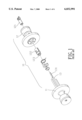
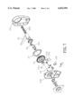
- FIG. 1 shows a typical tubular lock 10 which comprises an outer handle body 11 adapted to be mounted on the outer side of a door, and an inner handle body 12 adapted to be mounted on the inner side of the door.
- the outer and inner handle bodies 11 and 12 are interconnected by a spindle 13 which passes through a spindle hole of a latch mechanism (not shown) and which incorporates a mandrel 131 therein.
- the mandrel 131 is connected to a knob body 121 disposed inside the inner handle body 12.
- the spindle 13 also passes through a spindle hole 123 of a rotatable hollow cylinder 122.
- the mandrel 131 When the knob body 121 is turned manually, the mandrel 131 will move a locking element (not shown) disposed in the outer handle body 11 so that the hollow cylinder 122 and the spindle 13 are locked against rotation. In this situation, the tubular lock 10 is in a locked position. If the mandrel 131 is turned in a reversed direction, the locking element is moved to a releasing position, thereby releasing the cylinder 122 and the spindle 13 and unlocking the tubular lock 10. On the other hand, when the handle body 12 is rotated, the cylinder 122 and the spindle 13 can be turned to actuate the latch mechanism so that the door can be latched or unlatched.
- conventional tubular locks generally comprise a mandrel and a spindle which interconnect inner and outer handle bodies or levers and which are operable only through a manual operation. Improvements are therefore desirable so as to render conventional tubular locks operable via electric means.
- An object of the present invention is to provide a tubular lock which can be operated either manually or electrically.
- a tubular lock assembly for actuating a latch mechanism, comprises a support adapted to be mounted on an inner side of a door, a hollow cylinder having an outer end mounted on the support and an inner end extending inwardly from the support, a spindle extending axially inside the hollow cylinder and connected to the hollow cylinder for simultaneous rotation, the spindle being adapted to be connected to the latch mechanism, a rotary handle body connected to the inner end of the hollow cylinder, a driving wheel mounted on the support around the hollow cylinder and having a first gear part adjacent to the support and a second gear part adjacent to the handle body, an electric motor mounted on the support adjacent to and externally of the driving wheel, a first transmission mechanism mounted on the support and connected to the first gear part and the motor, and a second transmission mechanism mounted inside the handle body and connected to the second gear part and the spindle.
- the tubular lock assembly further includes a control unit to control the motor so as to limit the driving wheel to rotate within a limited angle.
- FIG. 1 shows a conventional tubular lock
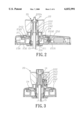
- FIG. 2 sectional side view of a first preferred embodiment of a tubular lock according to the present invention
- FIG. 3 is a sectional top view of the first embodiment
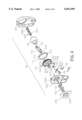
- FIG. 4 is an exploded view of the first embodiment
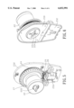
- FIG. 5 is a front perspective view of the first embodiment
- FIG. 6 is a rear perspective view of the first embodiment
- FIG. 7 shows an exploded view of a second preferred embodiment of the present invention.
- FIG. 8 is a front perspective view of the second embodiment.
- FIG. 9 is a rear perspective view of the second embodiment.
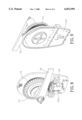
- a tubular lock embodying the present invention is designated by numeral 20 and includes a support formed by a cover 231 and a base 232 which are coupled together via interlocking means (not shown).
- a positioning plate 230 is fixed to the base 231 opposite to the cover 231.
- a hollow cylinder 221 is mounted rotatably on the base 232 and extends into a hole 2320 of a cup portion 2321 of the base 232.
- An inner end of the hollow cylinder 221, which will be located at an inner side of the door, is connected to a rotary handle body 22 which incorporates a turning knob body 222.
- the outer end of the cylinder 221 has a rectangular spindle hole 224 for passage of a rotary spindle 15 which is adapted to connect with a latch mechanism (not shown) that will be mounted inside a door.
- the spindle 15 has a rectangular cross-section to engage the spindle hole 224 of the cylinder 221 so that the spindle 15 can be turned via rotation of the rotary handle 22 and the cylinder 221 SO as to latch or unlatch the door in a conventional way.
- a torsion spring 211 and a restraining plate 230 are sleeved around the outer end of the hollow cylinder 221 between the base plate 232 and the positioning plate 230.
- the torsion spring 22 cooperates with the restraining plate 230 and controls the rotation of the hollow cylinder 221 SO that, after the cylinder 221 is turned in one direction, it can be returned to its original position by the action of the torsion spring 211.
- the spindle 15 which is shown partially in FIGS. 2 and 3, will extend towards the outer side of the door from a hole 2301 of the positioning plate 230 SO as to connect with the latch mechanism and an outer handle body (not shown) which will be mounted on the outer side of the door.
- the spindle 15 has a mandrel 14 which extends into the handle body 22 and is inserted fittingly in the knob body 222.
- the knob body 222 is in the form of a sleeve body and is provided with a plurality of axially extending gear teeth 223.
- a knob cap 222a is connected to the knob body 222 and projects outward from the handle body 22.
- a driving wheel 24 is disposed around the cylinder 221 and has a rim 243 mounted on a cup portion 2321 of the base plate 232.
- the driving wheel 24 has a varying cross-section.
- An internal gear part 241 is formed at one end of the driving wheel 24 adjacent to the handle body 22, and an external gear part 242 is formed at the other end of the driving wheel 24.
- the cross-section of the external gear part 242 is greater than that of the internal gear part 241.
- a motor 250 is mounted on the base plate 232 to operate the driving wheel 24 via a first transmission mechanism.
- the first transmission mechanism includes a bevel gear 252 mounted on an output shaft 251 of the motor 250, and a gear 253 mounted on the base plate 232 adjacent to the bevel gear 252 and including a bevel gear part 2531 and a spur gear part 2532.
- the bevel gear part 2531 engages the bevel gear 252, while the spur gear part 2532 engages the external gear part 242 of the driving wheel 24 so as to drive the driving wheel 24.
- the internal gear part 241 of the driving wheel 24 is connected to the knob body 222 via a second transmission mechanism 26 so as to rotate the knob body 222.
- the second transmission mechanism 26 is mounted inside the handle body 22 and includes a transmission shaft 261, a pair of transmission gears 262 mounted on the transmission shaft 261 in an axially spaced apart position, and another transmission gear 263.
- One of the transmission gears 262 extends into and engages the internal gear part 241.
- the other transmission gear 262 engages the transmission gear 263 which in turn engages the gear teeth 223 of the knob body 222.
- the motion of the driving wheel 24 can be transmitted to the knob body 222 and the mandrel 14 which will then move the spindle 15 to latch or unlatch the door. As such, the door can be latched or unlatched by energizing the motor 250.
- a control unit for controlling and limiting the rotation of the driving wheel 24 includes a hollow limit plate 27 disposed around and connected to the driving wheel 24 for simultaneous rotation therewith, and a pair of micro-switches 29.
- the micro-switches 29 are mounted on the base plate 232 on two sides of the motor 250.
- the limit plate 27 is provided with axially projecting tongues 272 adjacent to the external gear part 241, and the tongues 272 function to contact and actuate the micro-switches 29.
- the control unit further includes a pair of electric connectors 28 which are connected electrically to the micro-switches 29, respectively.
- the electric connectors 28 are also mounted on the base plate 232 and can be connected to an external control circuit (not shown), such as a coded control circuit, for remote control of the cylinder lock 20 of the present invention.
- FIGS. 7 and 8 A second preferred embodiment of the present invention is shown in FIGS. 7 and 8, wherein elements similar to those illustrated in the previous embodiment are represented by like numerals.
- the second embodiment differs from the previous embodiment only in that a lever handle 30 is used in the second embodiment in place of the handle body 22 of the previous embodiment.
Abstract
An electrically operable tubular lock assembly includes a support to be mounted on an inner side of a door, a hollow cylinder having an outer end mounted on the support and an inner end extending inwardly from the support, a spindle extending axially inside the hollow cylinder and connected to the hollow cylinder for simultaneous rotation therewith, a rotary handle body connected to the inner end of the hollow cylinder, a driving wheel mounted on the support around the hollow cylinder and having a first gear part adjacent to the support and a second gear part adjacent to the handle body, an electric motor mounted on the support adjacent to and externally of the driving wheel, a first transmission mechanism mounted on the support and connected to the first gear part and the motor, and a second transmission mechanism mounted inside the handle body and connected to the second gear part and the spindle.
Description
1. Field of the Invention
The invention relates to a door lock, more particularly to a tubular lock that incorporates an electrically operated driving wheel to control the latching and unlatching operations of the tubular lock.
2. Description of the Related Art
Various forms of tubular locks have existed in the art. FIG. 1 shows a typical tubular lock 10 which comprises an outer handle body 11 adapted to be mounted on the outer side of a door, and an inner handle body 12 adapted to be mounted on the inner side of the door. The outer and inner handle bodies 11 and 12 are interconnected by a spindle 13 which passes through a spindle hole of a latch mechanism (not shown) and which incorporates a mandrel 131 therein. The mandrel 131 is connected to a knob body 121 disposed inside the inner handle body 12. The spindle 13 also passes through a spindle hole 123 of a rotatable hollow cylinder 122. When the knob body 121 is turned manually, the mandrel 131 will move a locking element (not shown) disposed in the outer handle body 11 so that the hollow cylinder 122 and the spindle 13 are locked against rotation. In this situation, the tubular lock 10 is in a locked position. If the mandrel 131 is turned in a reversed direction, the locking element is moved to a releasing position, thereby releasing the cylinder 122 and the spindle 13 and unlocking the tubular lock 10. On the other hand, when the handle body 12 is rotated, the cylinder 122 and the spindle 13 can be turned to actuate the latch mechanism so that the door can be latched or unlatched. As mentioned hereinabove, conventional tubular locks generally comprise a mandrel and a spindle which interconnect inner and outer handle bodies or levers and which are operable only through a manual operation. Improvements are therefore desirable so as to render conventional tubular locks operable via electric means.
An object of the present invention is to provide a tubular lock which can be operated either manually or electrically.
According to the present invention, a tubular lock assembly for actuating a latch mechanism, comprises a support adapted to be mounted on an inner side of a door, a hollow cylinder having an outer end mounted on the support and an inner end extending inwardly from the support, a spindle extending axially inside the hollow cylinder and connected to the hollow cylinder for simultaneous rotation, the spindle being adapted to be connected to the latch mechanism, a rotary handle body connected to the inner end of the hollow cylinder, a driving wheel mounted on the support around the hollow cylinder and having a first gear part adjacent to the support and a second gear part adjacent to the handle body, an electric motor mounted on the support adjacent to and externally of the driving wheel, a first transmission mechanism mounted on the support and connected to the first gear part and the motor, and a second transmission mechanism mounted inside the handle body and connected to the second gear part and the spindle. The tubular lock assembly further includes a control unit to control the motor so as to limit the driving wheel to rotate within a limited angle.
Other features and advantages of the present invention will become apparent in the following detailed description of the preferred embodiment with reference to the accompanying drawings, of which:
FIG. 1 shows a conventional tubular lock;
FIG. 2 sectional side view of a first preferred embodiment of a tubular lock according to the present invention;
FIG. 3 is a sectional top view of the first embodiment;
FIG. 4 is an exploded view of the first embodiment;
FIG. 5 is a front perspective view of the first embodiment;
FIG. 6 is a rear perspective view of the first embodiment;
FIG. 7 shows an exploded view of a second preferred embodiment of the present invention;
FIG. 8 is a front perspective view of the second embodiment; and
FIG. 9 is a rear perspective view of the second embodiment.
Referring to FIGS. 2, 3 and 4, a tubular lock embodying the present invention is designated by numeral 20 and includes a support formed by a cover 231 and a base 232 which are coupled together via interlocking means (not shown). A positioning plate 230 is fixed to the base 231 opposite to the cover 231. A hollow cylinder 221 is mounted rotatably on the base 232 and extends into a hole 2320 of a cup portion 2321 of the base 232. An inner end of the hollow cylinder 221, which will be located at an inner side of the door, is connected to a rotary handle body 22 which incorporates a turning knob body 222. The outer end of the cylinder 221 has a rectangular spindle hole 224 for passage of a rotary spindle 15 which is adapted to connect with a latch mechanism (not shown) that will be mounted inside a door. In this embodiment, the spindle 15 has a rectangular cross-section to engage the spindle hole 224 of the cylinder 221 so that the spindle 15 can be turned via rotation of the rotary handle 22 and the cylinder 221 SO as to latch or unlatch the door in a conventional way.
A torsion spring 211 and a restraining plate 230 are sleeved around the outer end of the hollow cylinder 221 between the base plate 232 and the positioning plate 230. As in the conventional tubular lock, the torsion spring 22 cooperates with the restraining plate 230 and controls the rotation of the hollow cylinder 221 SO that, after the cylinder 221 is turned in one direction, it can be returned to its original position by the action of the torsion spring 211.
The spindle 15, which is shown partially in FIGS. 2 and 3, will extend towards the outer side of the door from a hole 2301 of the positioning plate 230 SO as to connect with the latch mechanism and an outer handle body (not shown) which will be mounted on the outer side of the door. There will be a locking element (not shown) associated with the outer handle body for locking the spindle 15 against rotation. The spindle 15 has a mandrel 14 which extends into the handle body 22 and is inserted fittingly in the knob body 222. The knob body 222 is in the form of a sleeve body and is provided with a plurality of axially extending gear teeth 223. A knob cap 222a is connected to the knob body 222 and projects outward from the handle body 22. When the mandrel 14 is turned via the knob body 222, the spindle 15 can be released from the aforesaid locking element and permitted to operate the latch mechanism in a conventional way.
A driving wheel 24 is disposed around the cylinder 221 and has a rim 243 mounted on a cup portion 2321 of the base plate 232. The driving wheel 24 has a varying cross-section. An internal gear part 241 is formed at one end of the driving wheel 24 adjacent to the handle body 22, and an external gear part 242 is formed at the other end of the driving wheel 24. The cross-section of the external gear part 242 is greater than that of the internal gear part 241. A motor 250 is mounted on the base plate 232 to operate the driving wheel 24 via a first transmission mechanism. In this embodiment, the first transmission mechanism includes a bevel gear 252 mounted on an output shaft 251 of the motor 250, and a gear 253 mounted on the base plate 232 adjacent to the bevel gear 252 and including a bevel gear part 2531 and a spur gear part 2532. The bevel gear part 2531 engages the bevel gear 252, while the spur gear part 2532 engages the external gear part 242 of the driving wheel 24 so as to drive the driving wheel 24.
The internal gear part 241 of the driving wheel 24 is connected to the knob body 222 via a second transmission mechanism 26 so as to rotate the knob body 222. In this embodiment, the second transmission mechanism 26 is mounted inside the handle body 22 and includes a transmission shaft 261, a pair of transmission gears 262 mounted on the transmission shaft 261 in an axially spaced apart position, and another transmission gear 263. One of the transmission gears 262 extends into and engages the internal gear part 241. The other transmission gear 262 engages the transmission gear 263 which in turn engages the gear teeth 223 of the knob body 222. Via the second transmission mechanism 26, the motion of the driving wheel 24 can be transmitted to the knob body 222 and the mandrel 14 which will then move the spindle 15 to latch or unlatch the door. As such, the door can be latched or unlatched by energizing the motor 250.
Referring to FIGS. 5 and 6 in combination with FIG. 4, a control unit for controlling and limiting the rotation of the driving wheel 24 includes a hollow limit plate 27 disposed around and connected to the driving wheel 24 for simultaneous rotation therewith, and a pair of micro-switches 29. The micro-switches 29 are mounted on the base plate 232 on two sides of the motor 250. The limit plate 27 is provided with axially projecting tongues 272 adjacent to the external gear part 241, and the tongues 272 function to contact and actuate the micro-switches 29. When the motor 250 is energized, the driving wheel 24 is rotated, and one of the tongues 272 will move to and then contact one of the micro-switches 29, thereby de-energizing the motor 250 and limiting the driving wheel 24 to rotate within a limited angle. The control unit further includes a pair of electric connectors 28 which are connected electrically to the micro-switches 29, respectively. The electric connectors 28 are also mounted on the base plate 232 and can be connected to an external control circuit (not shown), such as a coded control circuit, for remote control of the cylinder lock 20 of the present invention.
A second preferred embodiment of the present invention is shown in FIGS. 7 and 8, wherein elements similar to those illustrated in the previous embodiment are represented by like numerals. The second embodiment differs from the previous embodiment only in that a lever handle 30 is used in the second embodiment in place of the handle body 22 of the previous embodiment.
While the present invention has been described in connection with what is considered the most practical and preferred embodiments, it is understood that this invention is not limited to the disclosed embodiments but is intended to cover various arrangements included within the spirit and scope of the broadest interpretation so as to encompass all such modifications and equivalent arrangements.
Claims (8)
1. A tubular lock assembly for actuating a door latch mechanism, comprising:
a support adapted to be mounted on on an inner side of a door;
a hollow cylinder having an outer end mounted on said support and an inner end extending inwardly from said support;
a spindle extending axially inside said hollow cylinder and connected to said hollow cylinder for simultaneous rotation therewith, said spindle being adapted to be connected to the latch mechanism;
a rotary handle body connected to said inner end of said hollow cylinder;
a driving wheel mounted on said support around said hollow cylinder and having a first gear part adjacent to said support and a second gear part adjacent to said handle body;
an electric motor mounted on said support adjacent to and externally of said driving wheel;
a first transmission mechanism mounted on said support and connected to said first gear part and said motor; and
a second transmission mechanism mounted inside said handle body and connected to said second gear part and said spindle.
2. The tubular lock assembly as claimed in claim 1, further comprising a control unit to control said motor so as to limit said driving wheel to rotate within a limited angle.
3. The tubular lock assembly as claimed in claim 2, wherein said driving wheel is hollow and has a varying cross-section, said first gear part is an external gear part, and said second gear part is an internal gear part, said external gear part having a cross-section greater than that of said internal gear part.
4. The tubular lock assembly as claimed in claim 3, wherein said second transmission mechanism includes a transmission shaft mounted inside said handle body adjacent to said spindle and extending into said internal gear part axially of said spindle, and transmission gears mounted on said transmission shaft and driven by said internal gear part.
5. The tubular lock assembly as claimed in claim 4, further comprising a knob body sleeved around said spindle inside said handle body, said knob body having a periphery formed with axially extending gear teeth and being rotatable via said transmission gears.
6. The tubular lock assembly as claimed in claim 5, wherein said knob body has a manually operable knob cap connected thereto and projecting from said handle body to the inner side of the door.
7. The tubular lock assembly as claimed in claim 5, wherein said first transmission mechanism includes transmission gears which are connected to said motor and said external gear part.
8. The tubular lock assembly as claimed in claim 3, wherein said control unit includes a hollow limit plate disposed around said driving wheel for simultaneous rotation therewith and having tongues extending adjacent to said external gear part, and a micro-switch mounted on said base plate adjacent to said external gear part and electrically connected to said motor, said micro-switch being actuated by said tongues to control said motor.
Priority Applications (1)
| Application Number | Priority Date | Filing Date | Title |
|---|---|---|---|
| US09/300,679 US6032991A (en) | 1999-04-27 | 1999-04-27 | Electrically operable tubular lock |
Applications Claiming Priority (1)
| Application Number | Priority Date | Filing Date | Title |
|---|---|---|---|
| US09/300,679 US6032991A (en) | 1999-04-27 | 1999-04-27 | Electrically operable tubular lock |
Publications (1)
| Publication Number | Publication Date |
|---|---|
| US6032991A true US6032991A (en) | 2000-03-07 |
Family
ID=23160149
Family Applications (1)
| Application Number | Title | Priority Date | Filing Date |
|---|---|---|---|
| US09/300,679 Expired - Fee Related US6032991A (en) | 1999-04-27 | 1999-04-27 | Electrically operable tubular lock |
Country Status (1)
| Country | Link |
|---|---|
| US (1) | US6032991A (en) |
Cited By (15)
| Publication number | Priority date | Publication date | Assignee | Title |
|---|---|---|---|---|
| US6418765B1 (en) * | 2000-07-03 | 2002-07-16 | Ming-Hsiang Chiu | Motor-driven lock |
| US6460903B1 (en) * | 2000-10-31 | 2002-10-08 | Summit Automation Co., Ltd | Locking mechanism of electronic lock |
| US6609736B2 (en) * | 2001-10-17 | 2003-08-26 | Kinyo Co., Ltd. | Horizontal motor-driven lock |
| US6619710B1 (en) * | 2002-09-10 | 2003-09-16 | Taiwan Fu Hsing Industrial Co., Ltd. | Adjustable lock for various door thicknesses |
| US20030209043A1 (en) * | 2002-05-09 | 2003-11-13 | Tsun-Tsai Yeh | Electronically-driven lock |
| US20040040353A1 (en) * | 2002-08-30 | 2004-03-04 | Yu Jer Ming | Door lock with a clutch having a cam-styled axle sleeve |
| US6725693B2 (en) * | 2002-08-30 | 2004-04-27 | Jer Ming Yu | Door lock with a clutch having a cam-styled axle sleeve |
| US20060081024A1 (en) * | 2004-10-18 | 2006-04-20 | Schlage Lock Company | Door handle insert |
| DE102006039843A1 (en) * | 2006-08-25 | 2008-02-28 | Fitness Services And Finance Ag | Lock for use in doors or other devices with restricted access comprises a release element that is integrated in an actuation device and can be operated mechanically uncoupled from the actuation device |
| US20090211320A1 (en) * | 2008-02-27 | 2009-08-27 | Wen-Pin Wu | Electro-mechanical lock structure |
| US20090229328A1 (en) * | 2008-03-14 | 2009-09-17 | Taiwan Fu Hsing Industrial Co., Ltd. | Electro-mechanical lock structure |
| US20100212381A1 (en) * | 2009-02-23 | 2010-08-26 | Lien-Hsi Huang | Electro-mechanical lock assembly |
| US20110227743A1 (en) * | 2010-03-18 | 2011-09-22 | Mark Kilbourne | Remotely actuatable locking system and method for forming doors for accommodating such systems |
| US8555684B1 (en) * | 2013-01-21 | 2013-10-15 | Jie-Fu Chen | Electronic lock |
| US20140300116A1 (en) * | 2013-04-03 | 2014-10-09 | Alexander Hellwig | System For Interlocking and Unlocking a Sliding Door |
Citations (6)
| Publication number | Priority date | Publication date | Assignee | Title |
|---|---|---|---|---|
| US4438962A (en) * | 1981-10-02 | 1984-03-27 | Emhart Industries, Inc. | Alternate manually and electrically actuated bolt |
| US5040391A (en) * | 1990-08-07 | 1991-08-20 | Taiwan Fu Hsing Industry Co., Ltd. | Structure for controlling the dead bolt used in an electronic lock |
| US5544507A (en) * | 1994-02-15 | 1996-08-13 | Taiwan Fu Hsing Industrial Co., Ltd. | Door lock assembly |
| US5626039A (en) * | 1995-04-12 | 1997-05-06 | Solari; Antonio | Electronic safety-lock |
| US5782118A (en) * | 1996-07-16 | 1998-07-21 | Schlage Lock Company | Lockset with motorized system for locking and unlocking |
| US5837365A (en) * | 1996-04-08 | 1998-11-17 | The Penn State Research Foundation | Hydrophilic polypropylene membranes |
-
1999
- 1999-04-27 US US09/300,679 patent/US6032991A/en not_active Expired - Fee Related
Patent Citations (6)
| Publication number | Priority date | Publication date | Assignee | Title |
|---|---|---|---|---|
| US4438962A (en) * | 1981-10-02 | 1984-03-27 | Emhart Industries, Inc. | Alternate manually and electrically actuated bolt |
| US5040391A (en) * | 1990-08-07 | 1991-08-20 | Taiwan Fu Hsing Industry Co., Ltd. | Structure for controlling the dead bolt used in an electronic lock |
| US5544507A (en) * | 1994-02-15 | 1996-08-13 | Taiwan Fu Hsing Industrial Co., Ltd. | Door lock assembly |
| US5626039A (en) * | 1995-04-12 | 1997-05-06 | Solari; Antonio | Electronic safety-lock |
| US5837365A (en) * | 1996-04-08 | 1998-11-17 | The Penn State Research Foundation | Hydrophilic polypropylene membranes |
| US5782118A (en) * | 1996-07-16 | 1998-07-21 | Schlage Lock Company | Lockset with motorized system for locking and unlocking |
Cited By (19)
| Publication number | Priority date | Publication date | Assignee | Title |
|---|---|---|---|---|
| US6418765B1 (en) * | 2000-07-03 | 2002-07-16 | Ming-Hsiang Chiu | Motor-driven lock |
| US6460903B1 (en) * | 2000-10-31 | 2002-10-08 | Summit Automation Co., Ltd | Locking mechanism of electronic lock |
| US6609736B2 (en) * | 2001-10-17 | 2003-08-26 | Kinyo Co., Ltd. | Horizontal motor-driven lock |
| US20030209043A1 (en) * | 2002-05-09 | 2003-11-13 | Tsun-Tsai Yeh | Electronically-driven lock |
| US20040040353A1 (en) * | 2002-08-30 | 2004-03-04 | Yu Jer Ming | Door lock with a clutch having a cam-styled axle sleeve |
| US6725693B2 (en) * | 2002-08-30 | 2004-04-27 | Jer Ming Yu | Door lock with a clutch having a cam-styled axle sleeve |
| US6758070B2 (en) * | 2002-08-30 | 2004-07-06 | Jer Ming Yu | Door lock with a clutch having a cam-styled axle sleeve |
| US6619710B1 (en) * | 2002-09-10 | 2003-09-16 | Taiwan Fu Hsing Industrial Co., Ltd. | Adjustable lock for various door thicknesses |
| US20060081024A1 (en) * | 2004-10-18 | 2006-04-20 | Schlage Lock Company | Door handle insert |
| DE102006039843A1 (en) * | 2006-08-25 | 2008-02-28 | Fitness Services And Finance Ag | Lock for use in doors or other devices with restricted access comprises a release element that is integrated in an actuation device and can be operated mechanically uncoupled from the actuation device |
| US20090211320A1 (en) * | 2008-02-27 | 2009-08-27 | Wen-Pin Wu | Electro-mechanical lock structure |
| US20090229328A1 (en) * | 2008-03-14 | 2009-09-17 | Taiwan Fu Hsing Industrial Co., Ltd. | Electro-mechanical lock structure |
| US7770423B2 (en) * | 2008-03-14 | 2010-08-10 | Taiwan Fu Hsing Industrial Co., Ltd | Electro-mechanical lock structure |
| US20100212381A1 (en) * | 2009-02-23 | 2010-08-26 | Lien-Hsi Huang | Electro-mechanical lock assembly |
| US7827837B2 (en) * | 2009-02-23 | 2010-11-09 | Taiwan Fu Hsing Industrial Co., Ltd. | Electro-mechanical lock assembly |
| US20110227743A1 (en) * | 2010-03-18 | 2011-09-22 | Mark Kilbourne | Remotely actuatable locking system and method for forming doors for accommodating such systems |
| US8952782B2 (en) * | 2010-03-18 | 2015-02-10 | Mark Kilbourne | Remotely actuatable locking system and method for forming doors for accommodating such systems |
| US8555684B1 (en) * | 2013-01-21 | 2013-10-15 | Jie-Fu Chen | Electronic lock |
| US20140300116A1 (en) * | 2013-04-03 | 2014-10-09 | Alexander Hellwig | System For Interlocking and Unlocking a Sliding Door |
Similar Documents
| Publication | Publication Date | Title |
|---|---|---|
| US6032991A (en) | Electrically operable tubular lock | |
| US6807834B2 (en) | Electric door lock with a coupling mechanism for selective engagement between a deadbolt operating spindle and a door handle | |
| US6517127B1 (en) | Electric door lock | |
| US6471257B1 (en) | Electric door lock | |
| US5647234A (en) | Vehicle locking system | |
| US5531086A (en) | Keyless entry deadbolt lock | |
| US8291733B2 (en) | Electric door lock | |
| US20070051145A1 (en) | Electric lock | |
| US20090025438A1 (en) | Lockset having an electrically operated clutch to control transmission of rotation from an outside handle to an outside spindle | |
| JP2784950B2 (en) | Door lock device for automobile | |
| JP2004197377A (en) | Door opening/closing device for vehicle | |
| JP2855561B2 (en) | Super lock mechanism in vehicle door lock device | |
| US7387005B2 (en) | Bathroom lock device having an automatically unlocking structure | |
| US5460417A (en) | Tubular lock assembly | |
| US6406072B1 (en) | Drive device for an electrically operated lock | |
| US11808059B2 (en) | Lock for door | |
| US7472571B1 (en) | Two-handled lock | |
| JPH0325590B2 (en) | ||
| US5482335A (en) | Tubular lock assembly | |
| KR100543829B1 (en) | Doorlock device automatic and hand-operated control combined structure | |
| US11840868B2 (en) | Vehicle door lock device | |
| JPH0816421B2 (en) | Vehicle locking device | |
| US11499348B2 (en) | Power child lock device | |
| JPH06102943B2 (en) | Door lock device | |
| GB2291109A (en) | A vehicle locking system |
Legal Events
| Date | Code | Title | Description |
|---|---|---|---|
| REMI | Maintenance fee reminder mailed | ||
| LAPS | Lapse for failure to pay maintenance fees | ||
| FP | Lapsed due to failure to pay maintenance fee |
Effective date: 20040307 |
|
| STCH | Information on status: patent discontinuation |
Free format text: PATENT EXPIRED DUE TO NONPAYMENT OF MAINTENANCE FEES UNDER 37 CFR 1.362 |