US6032561A - Apparatus for ultrasonic cutting of food products - Google Patents
Apparatus for ultrasonic cutting of food products Download PDFInfo
- Publication number
- US6032561A US6032561A US08/933,165 US93316597A US6032561A US 6032561 A US6032561 A US 6032561A US 93316597 A US93316597 A US 93316597A US 6032561 A US6032561 A US 6032561A
- Authority
- US
- United States
- Prior art keywords
- food product
- knife assembly
- knife
- cutting
- moving
- Prior art date
- Legal status (The legal status is an assumption and is not a legal conclusion. Google has not performed a legal analysis and makes no representation as to the accuracy of the status listed.)
- Expired - Fee Related
Links
Images


Classifications
-
- B—PERFORMING OPERATIONS; TRANSPORTING
- B26—HAND CUTTING TOOLS; CUTTING; SEVERING
- B26D—CUTTING; DETAILS COMMON TO MACHINES FOR PERFORATING, PUNCHING, CUTTING-OUT, STAMPING-OUT OR SEVERING
- B26D7/00—Details of apparatus for cutting, cutting-out, stamping-out, punching, perforating, or severing by means other than cutting
- B26D7/08—Means for treating work or cutting member to facilitate cutting
- B26D7/086—Means for treating work or cutting member to facilitate cutting by vibrating, e.g. ultrasonically
-
- A—HUMAN NECESSITIES
- A21—BAKING; EDIBLE DOUGHS
- A21C—MACHINES OR EQUIPMENT FOR MAKING OR PROCESSING DOUGHS; HANDLING BAKED ARTICLES MADE FROM DOUGH
- A21C15/00—Apparatus for handling baked articles
- A21C15/04—Cutting or slicing machines or devices specially adapted for baked articles other than bread
-
- B—PERFORMING OPERATIONS; TRANSPORTING
- B26—HAND CUTTING TOOLS; CUTTING; SEVERING
- B26D—CUTTING; DETAILS COMMON TO MACHINES FOR PERFORATING, PUNCHING, CUTTING-OUT, STAMPING-OUT OR SEVERING
- B26D1/00—Cutting through work characterised by the nature or movement of the cutting member or particular materials not otherwise provided for; Apparatus or machines therefor; Cutting members therefor
- B26D1/01—Cutting through work characterised by the nature or movement of the cutting member or particular materials not otherwise provided for; Apparatus or machines therefor; Cutting members therefor involving a cutting member which does not travel with the work
- B26D1/04—Cutting through work characterised by the nature or movement of the cutting member or particular materials not otherwise provided for; Apparatus or machines therefor; Cutting members therefor involving a cutting member which does not travel with the work having a linearly-movable cutting member
- B26D1/06—Cutting through work characterised by the nature or movement of the cutting member or particular materials not otherwise provided for; Apparatus or machines therefor; Cutting members therefor involving a cutting member which does not travel with the work having a linearly-movable cutting member wherein the cutting member reciprocates
-
- B—PERFORMING OPERATIONS; TRANSPORTING
- B26—HAND CUTTING TOOLS; CUTTING; SEVERING
- B26D—CUTTING; DETAILS COMMON TO MACHINES FOR PERFORATING, PUNCHING, CUTTING-OUT, STAMPING-OUT OR SEVERING
- B26D1/00—Cutting through work characterised by the nature or movement of the cutting member or particular materials not otherwise provided for; Apparatus or machines therefor; Cutting members therefor
- B26D1/56—Cutting through work characterised by the nature or movement of the cutting member or particular materials not otherwise provided for; Apparatus or machines therefor; Cutting members therefor involving a cutting member which travels with the work otherwise than in the direction of the cut, i.e. flying cutter
- B26D1/60—Cutting through work characterised by the nature or movement of the cutting member or particular materials not otherwise provided for; Apparatus or machines therefor; Cutting members therefor involving a cutting member which travels with the work otherwise than in the direction of the cut, i.e. flying cutter and is mounted on a movable carriage
-
- B—PERFORMING OPERATIONS; TRANSPORTING
- B26—HAND CUTTING TOOLS; CUTTING; SEVERING
- B26D—CUTTING; DETAILS COMMON TO MACHINES FOR PERFORATING, PUNCHING, CUTTING-OUT, STAMPING-OUT OR SEVERING
- B26D3/00—Cutting work characterised by the nature of the cut made; Apparatus therefor
- B26D3/24—Cutting work characterised by the nature of the cut made; Apparatus therefor to obtain segments other than slices, e.g. cutting pies
-
- B—PERFORMING OPERATIONS; TRANSPORTING
- B26—HAND CUTTING TOOLS; CUTTING; SEVERING
- B26D—CUTTING; DETAILS COMMON TO MACHINES FOR PERFORATING, PUNCHING, CUTTING-OUT, STAMPING-OUT OR SEVERING
- B26D5/00—Arrangements for operating and controlling machines or devices for cutting, cutting-out, stamping-out, punching, perforating, or severing by means other than cutting
- B26D5/005—Computer numerical control means
-
- B—PERFORMING OPERATIONS; TRANSPORTING
- B26—HAND CUTTING TOOLS; CUTTING; SEVERING
- B26D—CUTTING; DETAILS COMMON TO MACHINES FOR PERFORATING, PUNCHING, CUTTING-OUT, STAMPING-OUT OR SEVERING
- B26D5/00—Arrangements for operating and controlling machines or devices for cutting, cutting-out, stamping-out, punching, perforating, or severing by means other than cutting
- B26D5/007—Control means comprising cameras, vision or image processing systems
-
- B—PERFORMING OPERATIONS; TRANSPORTING
- B26—HAND CUTTING TOOLS; CUTTING; SEVERING
- B26D—CUTTING; DETAILS COMMON TO MACHINES FOR PERFORATING, PUNCHING, CUTTING-OUT, STAMPING-OUT OR SEVERING
- B26D5/00—Arrangements for operating and controlling machines or devices for cutting, cutting-out, stamping-out, punching, perforating, or severing by means other than cutting
- B26D5/20—Arrangements for operating and controlling machines or devices for cutting, cutting-out, stamping-out, punching, perforating, or severing by means other than cutting with interrelated action between the cutting member and work feed
- B26D5/30—Arrangements for operating and controlling machines or devices for cutting, cutting-out, stamping-out, punching, perforating, or severing by means other than cutting with interrelated action between the cutting member and work feed having the cutting member controlled by scanning a record carrier
- B26D5/34—Arrangements for operating and controlling machines or devices for cutting, cutting-out, stamping-out, punching, perforating, or severing by means other than cutting with interrelated action between the cutting member and work feed having the cutting member controlled by scanning a record carrier scanning being effected by a photosensitive device
-
- B—PERFORMING OPERATIONS; TRANSPORTING
- B26—HAND CUTTING TOOLS; CUTTING; SEVERING
- B26D—CUTTING; DETAILS COMMON TO MACHINES FOR PERFORATING, PUNCHING, CUTTING-OUT, STAMPING-OUT OR SEVERING
- B26D7/00—Details of apparatus for cutting, cutting-out, stamping-out, punching, perforating, or severing by means other than cutting
- B26D7/26—Means for mounting or adjusting the cutting member; Means for adjusting the stroke of the cutting member
- B26D7/2628—Means for adjusting the position of the cutting member
-
- B—PERFORMING OPERATIONS; TRANSPORTING
- B26—HAND CUTTING TOOLS; CUTTING; SEVERING
- B26D—CUTTING; DETAILS COMMON TO MACHINES FOR PERFORATING, PUNCHING, CUTTING-OUT, STAMPING-OUT OR SEVERING
- B26D5/00—Arrangements for operating and controlling machines or devices for cutting, cutting-out, stamping-out, punching, perforating, or severing by means other than cutting
- B26D5/20—Arrangements for operating and controlling machines or devices for cutting, cutting-out, stamping-out, punching, perforating, or severing by means other than cutting with interrelated action between the cutting member and work feed
-
- Y—GENERAL TAGGING OF NEW TECHNOLOGICAL DEVELOPMENTS; GENERAL TAGGING OF CROSS-SECTIONAL TECHNOLOGIES SPANNING OVER SEVERAL SECTIONS OF THE IPC; TECHNICAL SUBJECTS COVERED BY FORMER USPC CROSS-REFERENCE ART COLLECTIONS [XRACs] AND DIGESTS
- Y10—TECHNICAL SUBJECTS COVERED BY FORMER USPC
- Y10S—TECHNICAL SUBJECTS COVERED BY FORMER USPC CROSS-REFERENCE ART COLLECTIONS [XRACs] AND DIGESTS
- Y10S83/00—Cutting
- Y10S83/929—Particular nature of work or product
- Y10S83/932—Edible
-
- Y—GENERAL TAGGING OF NEW TECHNOLOGICAL DEVELOPMENTS; GENERAL TAGGING OF CROSS-SECTIONAL TECHNOLOGIES SPANNING OVER SEVERAL SECTIONS OF THE IPC; TECHNICAL SUBJECTS COVERED BY FORMER USPC CROSS-REFERENCE ART COLLECTIONS [XRACs] AND DIGESTS
- Y10—TECHNICAL SUBJECTS COVERED BY FORMER USPC
- Y10T—TECHNICAL SUBJECTS COVERED BY FORMER US CLASSIFICATION
- Y10T83/00—Cutting
- Y10T83/04—Processes
- Y10T83/0515—During movement of work past flying cutter
-
- Y—GENERAL TAGGING OF NEW TECHNOLOGICAL DEVELOPMENTS; GENERAL TAGGING OF CROSS-SECTIONAL TECHNOLOGIES SPANNING OVER SEVERAL SECTIONS OF THE IPC; TECHNICAL SUBJECTS COVERED BY FORMER USPC CROSS-REFERENCE ART COLLECTIONS [XRACs] AND DIGESTS
- Y10—TECHNICAL SUBJECTS COVERED BY FORMER USPC
- Y10T—TECHNICAL SUBJECTS COVERED BY FORMER US CLASSIFICATION
- Y10T83/00—Cutting
- Y10T83/465—Cutting motion of tool has component in direction of moving work
- Y10T83/4757—Tool carrier shuttles rectilinearly parallel to direction of work feed
-
- Y—GENERAL TAGGING OF NEW TECHNOLOGICAL DEVELOPMENTS; GENERAL TAGGING OF CROSS-SECTIONAL TECHNOLOGIES SPANNING OVER SEVERAL SECTIONS OF THE IPC; TECHNICAL SUBJECTS COVERED BY FORMER USPC CROSS-REFERENCE ART COLLECTIONS [XRACs] AND DIGESTS
- Y10—TECHNICAL SUBJECTS COVERED BY FORMER USPC
- Y10T—TECHNICAL SUBJECTS COVERED BY FORMER US CLASSIFICATION
- Y10T83/00—Cutting
- Y10T83/869—Means to drive or to guide tool
- Y10T83/8737—With tool positioning means synchronized with cutting stroke
Definitions
- the present invention relates generally to ultrasonic cutting. More particularly, the invention pertains to an improved apparatus for ultrasonic cutting of food products for use in automated systems.
- the application of ultrasonic food cutting has been introduced which provides many significant benefits for use in commercial food processing applications.
- the quality of the cut face is especially clean in visual appearance
- multi-layer food products can be easily cut without smearing of the layers
- the cutting operation is especially sanitary in comparison to conventional cutting methods, which is of significant importance in the food preparation industry.
- a cutting blade In known ultrasonic food product cutting machines, a cutting blade is generally caused to vibrate at 20-40 kHz to move a cutting tip of the blade rapidly back and forth. This very high frequency movement effectively reduces the co-efficient of friction to a very low level, enabling the blade to slide through the food product.
- a food product After each cut, a food product can be repositioned by a rotary table, for example, where multiple cuts in the product are desired. It may be appreciated that the proper positioning of the food product with the ultrasonic cutter is important, especially in cutting bakery products, such as pies and cakes, where the multiple cuts of the bakery product are to converge at a center point. However, movements of the food product to the ultrasonic cutter can often become problematic resulting in damage to the appearance of the product. Many food products, such as multi-layer bakery products, become relatively unstable after multiple cuts have been made. Accordingly, the start and stop motion of the food product to move and position the product to the ultrasonic cutter can become undesirable where damage to an unstable product occurs.
- the apparatus of the present invention differs from those previously proposed and employs a number of novel features that render it highly advantageous over the prior art, as well as solving the aforementioned problems.
- Another object of this invention is to provide an apparatus designed for use in automated systems of commercial food processing.
- Still another object of this invention is to provide an apparatus which allows for increased production capacity.
- Yet another object of this invention is to provide an apparatus which is well suited for cutting multi-layer food products, such as cakes and other bakery products, where such products typically require multiple cuts which render the product relatively unstable.
- an ultrasonic food product cutting apparatus includes a base frame having a conveyor mounted thereto.
- An ultrasonic knife assembly has a blade adapted for cutting the food product.
- a knife positioning assembly is mounted to the base frame and supports the ultrasonic knife assembly above the conveyor for moving the knife assembly to the food product in a cutting position therewith when the conveyor has moved the food product within a cutting range of the knife positioning assembly.
- the knife assembly is moved at a rate of speed synchronous to a rate of speed of the moving conveyor means to maintain the cutting position and allow the ultrasonic knife assembly to effectuate a smooth cut in the food product.
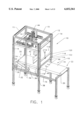
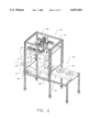
- FIG. 1 is a perspective view of a first embodiment of the present invention
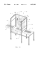
- FIG. 2 is a perspective view of a second embodiment of the present invention.
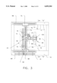
- FIG. 3 is an enlarged plan view of one embodiment of an ultrasonic knife positioning assembly for use with the first and second embodiments of the present invention
- FIG. 4 is side view of the knife positioning assembly taken along line 4--4 of FIG. 3;
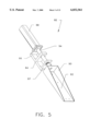
- FIG. 5 is a perspective view of a rotary axis assembly
- FIG. 6 is a diagrammatic perspective view illustrating a series of ultrasonic cuts being applied to a rectangular shaped food product
- FIG. 7 is a diagrammatic perspective view illustrating a series of ultrasonic cuts being applied to a round shaped food product
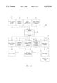
- FIG. 8 is a block diagram of the present invention.
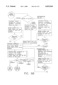
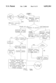
- FIG. 9 is a flowchart illustrating operational program logic of the second embodiment of the present invention.
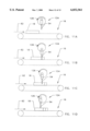
- FIGS. 10A-10D are side views diagrammatically illustrating the method of operation of the second embodiment
- FIGS. 11A-11D are side views diagrammatically illustrating the method of operation of a third embodiment.
- FIG. 12 is a perspective view of the third embodiment of the present invention.
- FIG. 1 an ultrasonic food product cutting apparatus 10 is illustrated in FIG. 1 for cutting food products.
- the apparatus 10 includes a base frame 12 formed of a plurality metal vertical and horizontal frame members 14,15 secured to one another.
- An infeed conveyor or conveyor assembly 16 is mounted to the base frame 12 for moving a food product 18 (FIG. 7) supported thereon.
- the conveyor assembly 16 includes a conveyor belt 19 mounted for rotation on an idler roller 20 mounted at a first or infeed end 22 of the conveyor assembly 16 and a drive roller 24 mounted at a second end 26 of the conveyor assembly 16.
- a drive shaft 28 extends from the drive roller 24 is connected to a sprocket 30.
- Chain 32 is operatively connected between sprocket 30 and motor sprocket 34.
- a shaft 36 is connected between sprocket 34 and an electric drive motor 38 of conventional design which provides rotational forces to drive the conveyor assembly 16 which is controlled by an infeed conveyor controller 17 (FIG. 8). It should be understood that other drive mechanisms of known design could be employed to drive the conveyor assembly 16.
- the apparatus is constructed for use in a indexing type mode where a food product is conveyed in a first direction indicated by the numeral 40 to a stationary position within a cutting range 42 of an ultrasonic knife positioning assembly 44. After cutting, as later described, the food product is conveyed away from the positioning assembly by moving the food product in the first direction 40, or alternatively in a second direction indicated by the numeral 46.
- the apparatus 10 as shown in a second embodiment of FIG. 2, includes a conveyor assembly 16 which operates continuously to move the food product 18 in a single horizontal direction indicated by the numeral 47 from an infeed end 48 to an outfeed end 50.
- Additional conveyor assemblies 53 constructed similarly to conveyor assembly 16 may be provided at the infeed and outfeed ends 48,50 for moving the food product 18 in an automated system to a succeeding food processing or packaging station.
- an ultrasonic knife assembly 52 has a blade 54 adapted for cutting the food product 18.
- the cutting action is a combination of the sharp cutting edge 56 and mechanical vibration of the blade 54.
- the edge is elongated and extends in a plane parallel with a support surface of the conveyor assembly.
- the blade 54 is designed to vibrate generally between 20 to 40 khz depending on the type of food product 18 in a longitudinal or piston type mode and is driven by an electro-mechanical transducer 58 including an ultrasonic generator and amplifier.
- the ultrasonic knife assembly 52 per se may be of the type commercially available for use in food cutting.
- the ultrasonic knife positioning assembly 44 is mounted to the base frame 12 and supports the ultrasonic knife assembly 52 above the conveyor belt 19 for moving the knife assembly 52 to the food product in a cutting position.
- the area of the cutting position is indicated by the numeral 60 (FIG. 3).
- the knife positioning assembly 44 provides movement of the knife assembly 44 about an x-axis 62, y-axis 64, and z-axis 66.
- a pair of servopneumatic x-cylinders 68 are secured to horizontal members 15 on opposite sides 70 of the frame 12.
- the x-cylinders 68 extend parallel to one another in a spaced apart relationship.
- An x-y cylinder connection bracket 72 is mounted to each of the x-cylinders 68 for movement in the x-axis 62 therewith.
- One of the x-cylinders 68 includes an x-transducer 69 operatively connected therewith.
- a servopneumatic y-cylinder 74 has opposite ends 76 with each end 76 mounted to one of the brackets 72.
- the y-cylinder 74 extends perpendicular to the x-cylinders 68 and generally across the width of the conveyor belt 19.
- a y-z connection bracket 78 is mounted to the y-cylinder 74 for movement in the y-axis 64 therewith.
- the y-cylinder 74 includes a y-transducer 75 operatively connected therewith.
- a servopneumatic z-cylinder 80 is mounted to the bracket 78 and extends vertically to provide movement in the z-axis 66 or vertical plane perpendicular to the planes of movement of the x-cylinders 68 and y-cylinder 74.
- the z-cylinder 80 includes a z-transducer 81 operatively connected therewith.
- servopneumatic cylinders 68,74,80, and corresponding transducers 69,75,81 these components per se are of conventional design and it should be understood that other known motor or actuator assemblies could be employed with the present invention, such as electric servomotors, servohydraulics, and mechanical drive mechanisms, where such assemblies would be configured in accordance with teachings of the present invention.
- a rotary motor assembly 82 is connected to the z-cylinder for movement therewith and provides rotational movement of the knife assembly 52 about the z-axis 66.
- the rotary motor assembly 82 includes a bracket 84 having upper and lower portions 86,87.
- a rotary motor and reducer 88 of conventional design is secured to the upper portion 86.
- a knife assembly support 90 is rotationally secured at the lower portion 87 of the bracket 84.
- the knife support 90 includes a mounting plate 92 adapted to mount the ultrasonic knife assembly 52 in fixed assembly therewith, as best illustrated in FIG. 4.
- a shaft 94 is interconnected between the motor 88 and knife assembly support 90 for transmitting rotational forces from the motor 88 to the knife assembly support 90.
- the motor 88 provides up to 360° of rotation to the knife assembly support 90 to allow for pie shaped cuts 92 in round food products where the blade 54 is center positioned above the food product 18 such that 180° of rotation of the blade 54 can produce cuts 92 at 360 ° around the food product 18.
- a control system 95 of the apparatus 10 is illustrated.
- Each of servopneumatic cylinders 68,74,80 are electronically connected to respective controllers 94.
- the rotary motor assembly 82 is electronically connected to controller 96.
- the controllers 94,96 work together to move the cutting blade 54 to specified positions dictated by a processor 98.
- the processor 98 is preferably a programmable logic controller or personal computer based system of conventional design.
- the controllers 94,96 and processor 98 operate using control algorithms which include a command signal to cause motion, a driver to respond to the command signal, and a feedback system which indicates the actual position of the system.
- the acceleration, speed, deceleration, and position of the cylinders can all be controlled to prescribed limits.
- the cutting blade 54 can be accelerated to the proper speed, maintained at that speed, decelerated to a stop, and returned to the stop position.
- the knife assembly 52 is moved at a rate of speed synchronous to a rate of speed of the moving conveyor 16 for maintaining the cutting position for a specific time period to allow the ultrasonic knife assembly 52 to effectuate a cut.
- the first part of the motion required for the x-axis consists of accelerating the cutting blade 54 to a linear speed that is the same as the linear speed of the conveyor 16 within the prescribed distance and time.
- the speed of the cutting blade 54 is then maintained at the matching speed to the conveyor 16 while the cut or cuts are being made.
- the cutting blade 54 is decelerated to a stop.
- the cutting blade 54 is then returned to its original position.
- the motion required for the y-axis is a movement to adjust the position to align the cutting blade 54 with the food product 18.
- the motion consists of an acceleration portion, a constant speed portion if required, and a deceleration portion to a stop at the final position.
- the motion required for the z-axis is a smooth movement down to perform the product cut and a rapid retraction of the blade 54 from the food product 18.
- the ultrasonic knife assembly 52 is activated at the start of the motion and deactivated after the return of the cutting blade to its original vertical position.
- the motion consists of a high acceleration period to obtain the required cutting speed, fast advance into the product at cutting speed, decelerating rapidly to a predetermined stop position which is sufficient to cut the product 18 but not damage the carrier of the product 18 or the conveyor 16, a rapid acceleration to the required retraction speed, retraction of the cutting blade 54 from the product 18, and then stopping at its original position.
- the stops on both the top and bottom of the travel are programmable by use of the control system 95 with processor 98.
- the motion required for rotation about an ⁇ axis 100 is a rapid rotary motion to move the cutting blade 54 from one rotary orientation to another.
- the motion consists of a high acceleration period, high speed rotary movement and high deceleration period to rotate the blade 54 from its initial position to its next required position.
- the cutting blade 54 can be activated at each position and the cutting can be accomplished by the proper movement in the z-axis as described above. After the final cut is made, the cutting blade 54 is rotated back to its original position.
- a product detector or sensor 102 such as a photoelectric sensor or vision camera of the type known in the art of optical sensing, is mounted at the infeed end 22 of the conveyor 16 and is electronically connected with the controllers 94 of the knife positioning assembly 44 through the processor 98 to sense the proximity of the food product 18 within the cutting range 42.
- the control system 95 is responsive to the sensor 102 to cause the knife positioning assembly 44 to move the knife assembly 52 to the food product 18 in the cutting position and for movement about the food product 18 for positioning the knife assembly 52 to effectuate a series of preselected cuts as desired.
- An encoder 104 is mounted at the infeed end 22 of the conveyor 16 and is electronically connected to the processor 98 for determining exact position and dimensions of the food product 18 as it moves past the product detector 102 at a specific rate of speed on the conveyor 16.
- Safety switches and electronic stop mechanisms 99 of conventional design may be employed to automatically stop the operation of the apparatus 10 when in use pursuant to a particular selected conditions being satisfied.
- an operator interface 106 is electronically connected with the processor 98.
- the operator interface 106 per se is of conventional design and when connected with the present invention it can be configured to allow a user to programmably select a shape of food product and a number of cuts to be given to the food product and where these selections may be saved as a formula for later use (FIGS. 9A and 9B). For example, referring to FIG. 6, a rectangular shaped food product is selected having a plurality of cuts 108 along the products width and length. Referring to FIG. 7, a round shaped food product is selected having a plurality of pie shaped cuts 92. It should be understood that food products of any size could be used, however, in baking applications round and rectangular shapes are particularly common.
- an infeed gate assembly 110 is provided which is raised and lowered when a food product 18 enters or exits the cutting range 42 when the apparatus 10 is operated in accordance with the first embodiment previously described.
- the gate assembly 110 includes an infeed gate controller 112 (FIG. 8) which is electronically interconnected between the processor 98 and an air piston 114 of the assembly.
- the assembly 110 includes a pair of slider brackets 116 secured to the frame 12 in opposing space apart relationship with one another at the first end 22 of the conveyor assembly 16.
- a gate member 118 has opposite sides 120.
- Each slider bracket 116 has a channel 122 for receiving a respective side 120 in slidable engagement therewith.
- the gate member has the air piston 114 connected therewith for actuating the gate member.
- FIGS. 9A and 9B a flowchart is provided which illustrates program logic being carried out during operation of the second embodiment of the apparatus 10 where the conveyor 16 moves continuously during the ultrasonic cutting. It should be understood that the program logic illustrates only one preferred embodiment and that alternative program logic could be employed in accordance with the purposes of the present invention described above.
- FIGS. 10A-10D a series of consecutive side views diagrammatically illustrate the method of operation of the second embodiment taken at various time increments.
- the blade 54 being actuated by a knife positioning assembly as previously described is caused to move towards a food product 18 which is moving continuously on a conveyor 16.
- the blade 54 meets the food product 18 and is momentarily positioned at a stationary position whereafter the blade 54 is caused to move in a common direction and speed with the food product 18 in a cutting position.
- FIG. 10C the blade 54 is shown effectuating a cut in the food product 18 while continuing to move with the food product 18.
- the blade 54 is shown in FIG. 10D as having reached an end of the cutting range of the blade 54 whereafter the blade 54 will be caused to reverse direction to move towards a succeeding food product 18 as shown in FIG. 10A.
- a third embodiment of the present invention is indicated by the numeral 123.
- the blade 54 of the third embodiment is operatively connected with an orbital knife positioning assembly 124.
- the assembly 124 provides rotary movement of the blade 54 in a vertical plane about an orbit 126 which is shown moving in a counter clockwise direction through the x-axis 62 and z-axis 66.
- Blade 54 is operatively connected with the ultrasonic knife assembly 52 as previously described.
- the knife assembly 52 is mounted to a knife support 128.
- the knife support 128 is rotatably mounted to a rotary mechanism 130 so that the blade 54 is maintained in a vertical plane.
- the rotary mechanism 130 provides the orbital movement of the assembly 124 and may include camming so that movement of the blade 54 at a lower portion of the orbit 126 (FIG. 11B) is timed to provide synchronized movement of the blade 54 with the food product 18 along the x-axis 62.
- FIGS. 11A-11D a series of consecutive side views diagrammatically illustrate the method of operation of the third embodiment taken at various time increments.
- the blade 54 is actuated by the knife positioning assembly 124 as previously described and is caused to move towards a food product 18 which is moving continuously on a conveyor 16.
- the blade 54 is shown in a cutting position as the blade 54 cuts the food product 18 and travels with the food product 18 at a common speed in the x-axis.
- the blade 54 is moved about the orbit 126 to form succeeding cuts in the food product 18, as shown in FIGS. 11C and 11D.
Abstract
Description
Claims (7)
Priority Applications (2)
| Application Number | Priority Date | Filing Date | Title |
|---|---|---|---|
| US08/933,165 US6032561A (en) | 1997-09-18 | 1997-09-18 | Apparatus for ultrasonic cutting of food products |
| PCT/US1998/019525 WO1999014021A1 (en) | 1997-09-18 | 1998-09-18 | Method and apparatus for ultrasonic cutting of food products |
Applications Claiming Priority (1)
| Application Number | Priority Date | Filing Date | Title |
|---|---|---|---|
| US08/933,165 US6032561A (en) | 1997-09-18 | 1997-09-18 | Apparatus for ultrasonic cutting of food products |
Publications (1)
| Publication Number | Publication Date |
|---|---|
| US6032561A true US6032561A (en) | 2000-03-07 |
Family
ID=25463487
Family Applications (1)
| Application Number | Title | Priority Date | Filing Date |
|---|---|---|---|
| US08/933,165 Expired - Fee Related US6032561A (en) | 1997-09-18 | 1997-09-18 | Apparatus for ultrasonic cutting of food products |
Country Status (2)
| Country | Link |
|---|---|
| US (1) | US6032561A (en) |
| WO (1) | WO1999014021A1 (en) |
Cited By (42)
| Publication number | Priority date | Publication date | Assignee | Title |
|---|---|---|---|---|
| US6368647B1 (en) * | 1998-12-29 | 2002-04-09 | Mars, Incorporated | Ultrasonically activated continuous slitter apparatus and method |
| US20020127310A1 (en) * | 1998-12-07 | 2002-09-12 | Capodieci Roberto A. | Cereal food product and method |
| US6517879B2 (en) | 1996-11-27 | 2003-02-11 | Mars Incorporated | Method and apparatus for ultrasonic molding |
| US6530767B1 (en) | 1996-08-22 | 2003-03-11 | Mars Incorporated | Ultrasonic forming of confectionery products |
| US20030097820A1 (en) * | 2001-09-26 | 2003-05-29 | Grano Gary R. | Ultrasonic method and apparatus for dividing pastries and inserting dividers |
| US6607765B2 (en) | 1996-08-22 | 2003-08-19 | Mars, Incorporated | Ultrasonic forming of confectionery products |
| NL1020274C2 (en) * | 2002-03-28 | 2003-09-30 | Storteboom Group B V | Meat cutting device, comprises meat supports and cutting knife moving perpendicular to each other |
| US6635292B2 (en) | 2001-10-26 | 2003-10-21 | Mars, Incorporated | Ultrasonic rotary forming of food products |
| US6655948B2 (en) | 2001-08-31 | 2003-12-02 | Mars, Incorporated | System of ultrasonic processing of pre-baked food product |
| US20030230054A1 (en) * | 2001-06-19 | 2003-12-18 | Capodieci Roberto A. | Method and system for ultrasonic sealing of food product packaging |
| FR2851886A1 (en) | 2003-03-07 | 2004-09-10 | Ermatec | Food slicing machine, to give cut slices for sale, has a cutting blade over the product support surface with reciprocating linear movements along the entry line and at right angles to it |
| GB2364894B (en) * | 2000-07-19 | 2004-11-03 | Fmc Corp | Three axis portioning method |
| WO2005044011A1 (en) * | 2003-11-06 | 2005-05-19 | Sarmasik Makine Sanayi Ve Ticaret A.S. | Unit cutting dough surface in equal depth |
| NL1025310C2 (en) * | 2004-01-23 | 2005-07-26 | Rademaker B V | Positioning device for croissants on conveyor belt is controlled using camera and dough product image processing system |
| WO2006030454A1 (en) * | 2004-09-16 | 2006-03-23 | Marel Hf | A portioning device |
| FR2882677A1 (en) * | 2005-03-07 | 2006-09-08 | Ermatec Sarl | Agroalimentary cutter comprises blades, which is carried by a mobile gallows by sliding with groove, belt system and engine, turret on a central shaft carrying the blades and a detector to determine the dimensions of a container |
| CN100372661C (en) * | 2005-07-13 | 2008-03-05 | 吴小良 | Machine for cutting plastic sealed body |
| US20100028516A1 (en) * | 2008-07-31 | 2010-02-04 | Kraft Foods Holding, Inc. | Production of cookies having large particulates using ultrasonic wirecutting |
| US20110000231A1 (en) * | 2009-07-01 | 2011-01-06 | Mccormick Stephen A | Method and apparatus for ultrasonic freezing |
| US20110185868A1 (en) * | 2010-01-29 | 2011-08-04 | Schmidt Richard F | Exact Weight Cutting System for Food Products |
| NL2004839C2 (en) * | 2010-06-08 | 2011-12-12 | Producon Automatisering B V | DEVICE AND METHOD FOR PROCESSING PIECES OF FOOD ON A TRANSPORT BAND. |
| FR2964586A1 (en) * | 2010-09-10 | 2012-03-16 | Sodeva Tds | Cutting system for cutting of e.g. cheese, has maintaining mechanism integrated into conveyor, and cutting blade linearly moving along vertical axis with respect to rotation axis of support allowing cut of straight and cylindrical products |
| FR2971447A1 (en) * | 2011-02-10 | 2012-08-17 | Sodeva Tds | Cutting system for cutting e.g. cheese bread, has rotary cutting blade that moves linearly along vertical axis or horizontal axis relative to axis of rotation of product for allowing portion of product to be cut |
| US20130205961A1 (en) * | 2012-02-14 | 2013-08-15 | Albert Handtmann Maschinenfabrik Gmbh & Co. Kg | Method and device for separating products |
| CN103862499A (en) * | 2014-03-13 | 2014-06-18 | 昆明理工大学 | Automatic feeding pastry slicer |
| JP2014111288A (en) * | 2012-12-05 | 2014-06-19 | Taga Electric Co Ltd | Ultrasonic wave cutter with oscillation mechanism |
| CN104369211A (en) * | 2014-09-29 | 2015-02-25 | 四川氟迪新能源有限公司 | Automatic rubber cutting machine |
| US20150343654A1 (en) * | 2011-06-07 | 2015-12-03 | Risco Usa Corporation | Machine, Method, and System for High Speed Cutting and Portioning of Extruded Products |
| CN105291156A (en) * | 2015-11-12 | 2016-02-03 | 黄积剑 | Ultrasonic automatic food cutting production line |
| US20160316770A1 (en) * | 2015-04-30 | 2016-11-03 | Radie B.V. | Device for Cutting Dough |
| CN108722578A (en) * | 2018-05-22 | 2018-11-02 | 徐州工程学院 | A kind of residents in rural community shredding facilities |
| CN110524589A (en) * | 2019-08-03 | 2019-12-03 | 广东智源机器人科技有限公司 | Food cutting device and baking machine |
| WO2020069781A1 (en) * | 2018-10-02 | 2020-04-09 | Fritsch Bakery Technologies GmbH & Co. KG | Device for stamping dough pieces |
| CN111390986A (en) * | 2020-03-20 | 2020-07-10 | 诺兰特新材料(北京)有限公司 | Cutting device of rubber material |
| CN111421599A (en) * | 2020-04-09 | 2020-07-17 | 何招香 | Cake leftover material cutting device |
| CN112476517A (en) * | 2020-11-06 | 2021-03-12 | 常德市同创包装有限公司 | Automatic shred device of banded food processing |
| US11090827B2 (en) * | 2017-08-21 | 2021-08-17 | Murata Manufacturing Co., Ltd. | Cutting device |
| US11191281B1 (en) | 2018-01-05 | 2021-12-07 | Tyson Foods, Inc. | Method and apparatus for conveying a meat product and using an ultrasonic knife for automated cutting of meat |
| US20210400992A1 (en) * | 2019-02-18 | 2021-12-30 | Cheoul Kyu SONG | Ultrasonic bread cutter |
| US11304423B2 (en) | 2018-05-01 | 2022-04-19 | Risco Usa Corporation | Apparatus, system, and method for high speed production of food product |
| US11446013B2 (en) | 2016-07-01 | 2022-09-20 | Swan Cytologics, Inc. | Method and apparatus for extracting and delivery of entities |
| US11944105B1 (en) | 2018-01-05 | 2024-04-02 | Tyson Foods, Inc. | Method and apparatus for conveying a meat product and using a knife for automated cutting of meat |
Families Citing this family (12)
| Publication number | Priority date | Publication date | Assignee | Title |
|---|---|---|---|---|
| ITBO20070562A1 (en) * | 2007-08-03 | 2009-02-04 | Machinery Innovation Engineeri | MACHINE FOR THE PRODUCTION OF CHEESE PORTIONS. |
| ITMO20080173A1 (en) * | 2008-06-12 | 2009-12-13 | Tecno Europa Srl | EQUIPMENT AND METHODS FOR FRACTIONING CERAMIC ARTICLES |
| GB2482858A (en) * | 2010-06-22 | 2012-02-22 | Noreen Salador | Hot wire food cutter |
| CN102848423A (en) * | 2012-09-29 | 2013-01-02 | 新麦机械(无锡)有限公司 | Ultrasonic cutting device for cutting cakes |
| ITPR20130071A1 (en) * | 2013-09-19 | 2015-03-20 | Corte Parma Alimentare S R L | METHOD FOR THE PRODUCTION OF A TRAY CONTAINING CHEESE PARTS |
| CN105818188B (en) * | 2016-05-30 | 2017-10-31 | 蒙城丽倩家具有限公司 | A kind of plastic plate cutting adjustable cutting mechanism in position |
| CN109169763B (en) * | 2016-11-14 | 2020-11-10 | 安徽麦吉食品有限公司 | Automatic western-style cake machine |
| CN106393244B (en) * | 2016-11-18 | 2018-06-29 | 重庆市臻憬科技开发有限公司 | Slicer knife rest |
| ES2613742B1 (en) * | 2016-12-09 | 2017-10-26 | Beorvalue, S.L. | PERSONALIZED CUTTING MACHINE OF BREAD OR SIMILAR MASS PARTS |
| CN110065151A (en) * | 2019-04-09 | 2019-07-30 | 四川科筑科技有限公司 | A kind of cutter device and its cutting method for gypsum board manufacture system |
| CN110154131A (en) * | 2019-06-02 | 2019-08-23 | 沈阳工业大学 | A kind of Boards wall formula miniature numerical control gasket cutting machine |
| CN114274197A (en) * | 2021-12-15 | 2022-04-05 | 武汉长青天成园林工程有限公司 | Device for rapidly shearing crape myrtle cuttings in large batch and using method |
Citations (20)
| Publication number | Priority date | Publication date | Assignee | Title |
|---|---|---|---|---|
| US1357241A (en) * | 1918-01-16 | 1920-11-02 | Robert C Mcgee | Cake-cutting machine |
| US3178974A (en) * | 1962-04-02 | 1965-04-20 | Moog Servocontrols Inc | Apparatus for working on a workpiece while moving |
| US3310855A (en) * | 1966-02-21 | 1967-03-28 | Orioli Alessandro | Apparatus for operating on continuously moving material with means to relate the speed of the tool carriage to that of the material |
| US3573859A (en) * | 1967-05-08 | 1971-04-06 | Cincinnatti Milacron Inc | Method for cutting sharp angles in material |
| US3800363A (en) * | 1972-12-29 | 1974-04-02 | Laitram Corp | Tuna butchering method and system |
| US3958482A (en) * | 1974-10-16 | 1976-05-25 | Nordisk Kartro Aktiebolag | Machine for cutting material |
| GB2087290A (en) * | 1980-11-14 | 1982-05-26 | Gerber Garment Technology Inc | Ultrasonic apparatus and method for cutting sheet material |
| US4386465A (en) * | 1981-03-31 | 1983-06-07 | Norio Ezaki | Cutting apparatus for frozen food |
| US4391168A (en) * | 1980-07-10 | 1983-07-05 | Gerber Garment Technology, Inc. | Method for cutting sheet material with a cutting wheel |
| US4554852A (en) * | 1983-07-26 | 1985-11-26 | Food Equipment Manufacturing Corporation | Cutting machine for slicing circular articles into wedges |
| EP0353415A1 (en) * | 1988-06-03 | 1990-02-07 | Societe Des Produits Nestle S.A. | Cutting device |
| GB2246739A (en) * | 1990-06-08 | 1992-02-12 | S R A Dev Ltd | Cutting an aperture in brittle material |
| US5195410A (en) * | 1988-05-10 | 1993-03-23 | S.R.A. Developments Limited | Cutting brittle materials |
| US5216614A (en) * | 1991-04-05 | 1993-06-01 | Gerber Garment Technology, Inc. | Apparatus and method for automatically cutting a length of sheet work material segment-by-segment |
| US5228372A (en) * | 1990-10-19 | 1993-07-20 | Nestec S.A. | Cutting device |
| US5301587A (en) * | 1991-10-30 | 1994-04-12 | Gfm Gesellschaft Fur Fertigungstechnik Und Maschinenbau Aktiengesellschaft | Method and cutting assembly for manufacturing three-dimensional shaped pieces from a pre-fabricated block of a material having large pores |
| US5365816A (en) * | 1993-06-22 | 1994-11-22 | Design Systems, Inc. | Beam cutter |
| WO1995030518A1 (en) * | 1994-05-05 | 1995-11-16 | Unilever Plc | Method of dividing a food block into portions |
| WO1996009919A1 (en) * | 1994-09-28 | 1996-04-04 | Unilever Plc | Ultrasonic cutting process |
| US5799555A (en) * | 1991-04-03 | 1998-09-01 | Fabio Perini S.P.A. | Machine for cutting logs of web material |
Family Cites Families (2)
| Publication number | Priority date | Publication date | Assignee | Title |
|---|---|---|---|---|
| US3589222A (en) * | 1970-06-12 | 1971-06-29 | Cincinnati Milacron Inc | Method for cutting material |
| ZA832592B (en) * | 1982-04-14 | 1984-01-25 | Nippon Denso Co | Method and apparatus for cutting continuous corrugated member |
-
1997
- 1997-09-18 US US08/933,165 patent/US6032561A/en not_active Expired - Fee Related
-
1998
- 1998-09-18 WO PCT/US1998/019525 patent/WO1999014021A1/en active Application Filing
Patent Citations (20)
| Publication number | Priority date | Publication date | Assignee | Title |
|---|---|---|---|---|
| US1357241A (en) * | 1918-01-16 | 1920-11-02 | Robert C Mcgee | Cake-cutting machine |
| US3178974A (en) * | 1962-04-02 | 1965-04-20 | Moog Servocontrols Inc | Apparatus for working on a workpiece while moving |
| US3310855A (en) * | 1966-02-21 | 1967-03-28 | Orioli Alessandro | Apparatus for operating on continuously moving material with means to relate the speed of the tool carriage to that of the material |
| US3573859A (en) * | 1967-05-08 | 1971-04-06 | Cincinnatti Milacron Inc | Method for cutting sharp angles in material |
| US3800363A (en) * | 1972-12-29 | 1974-04-02 | Laitram Corp | Tuna butchering method and system |
| US3958482A (en) * | 1974-10-16 | 1976-05-25 | Nordisk Kartro Aktiebolag | Machine for cutting material |
| US4391168A (en) * | 1980-07-10 | 1983-07-05 | Gerber Garment Technology, Inc. | Method for cutting sheet material with a cutting wheel |
| GB2087290A (en) * | 1980-11-14 | 1982-05-26 | Gerber Garment Technology Inc | Ultrasonic apparatus and method for cutting sheet material |
| US4386465A (en) * | 1981-03-31 | 1983-06-07 | Norio Ezaki | Cutting apparatus for frozen food |
| US4554852A (en) * | 1983-07-26 | 1985-11-26 | Food Equipment Manufacturing Corporation | Cutting machine for slicing circular articles into wedges |
| US5195410A (en) * | 1988-05-10 | 1993-03-23 | S.R.A. Developments Limited | Cutting brittle materials |
| EP0353415A1 (en) * | 1988-06-03 | 1990-02-07 | Societe Des Produits Nestle S.A. | Cutting device |
| GB2246739A (en) * | 1990-06-08 | 1992-02-12 | S R A Dev Ltd | Cutting an aperture in brittle material |
| US5228372A (en) * | 1990-10-19 | 1993-07-20 | Nestec S.A. | Cutting device |
| US5799555A (en) * | 1991-04-03 | 1998-09-01 | Fabio Perini S.P.A. | Machine for cutting logs of web material |
| US5216614A (en) * | 1991-04-05 | 1993-06-01 | Gerber Garment Technology, Inc. | Apparatus and method for automatically cutting a length of sheet work material segment-by-segment |
| US5301587A (en) * | 1991-10-30 | 1994-04-12 | Gfm Gesellschaft Fur Fertigungstechnik Und Maschinenbau Aktiengesellschaft | Method and cutting assembly for manufacturing three-dimensional shaped pieces from a pre-fabricated block of a material having large pores |
| US5365816A (en) * | 1993-06-22 | 1994-11-22 | Design Systems, Inc. | Beam cutter |
| WO1995030518A1 (en) * | 1994-05-05 | 1995-11-16 | Unilever Plc | Method of dividing a food block into portions |
| WO1996009919A1 (en) * | 1994-09-28 | 1996-04-04 | Unilever Plc | Ultrasonic cutting process |
Cited By (71)
| Publication number | Priority date | Publication date | Assignee | Title |
|---|---|---|---|---|
| US6530767B1 (en) | 1996-08-22 | 2003-03-11 | Mars Incorporated | Ultrasonic forming of confectionery products |
| US6607765B2 (en) | 1996-08-22 | 2003-08-19 | Mars, Incorporated | Ultrasonic forming of confectionery products |
| US6517879B2 (en) | 1996-11-27 | 2003-02-11 | Mars Incorporated | Method and apparatus for ultrasonic molding |
| US20020127310A1 (en) * | 1998-12-07 | 2002-09-12 | Capodieci Roberto A. | Cereal food product and method |
| US20020119225A1 (en) * | 1998-12-29 | 2002-08-29 | Capodieci Roberto A. | Ultrasonically activated continuous slitter apparatus and method |
| US6368647B1 (en) * | 1998-12-29 | 2002-04-09 | Mars, Incorporated | Ultrasonically activated continuous slitter apparatus and method |
| US8025000B2 (en) | 2000-07-19 | 2011-09-27 | John Bean Technologies Corporation | Three axis portioning method |
| GB2364894B8 (en) * | 2000-07-19 | 2010-07-07 | Fmc Corp | Three axis portioning method |
| US8166856B2 (en) | 2000-07-19 | 2012-05-01 | John Bean Technologies Corporation | Method for portioning foodstuff to user-specified shape |
| US9770838B2 (en) | 2000-07-19 | 2017-09-26 | John Bean Technologies Corporation | System for portioning foodstuff to user-specified shape |
| GB2364894B (en) * | 2000-07-19 | 2004-11-03 | Fmc Corp | Three axis portioning method |
| US8028503B2 (en) | 2001-06-19 | 2011-10-04 | Robert Bosch Gmbh | Method and system for ultrasonic sealing of food product packaging |
| US20040011452A1 (en) * | 2001-06-19 | 2004-01-22 | Capodieci Roberto A. | Method and system for ultrasonic sealing of food product packaging |
| US20030230054A1 (en) * | 2001-06-19 | 2003-12-18 | Capodieci Roberto A. | Method and system for ultrasonic sealing of food product packaging |
| US20060086068A1 (en) * | 2001-06-19 | 2006-04-27 | Capodieci Roberto A | Method and system for ultrasonic sealing of food product packaging |
| US6655948B2 (en) | 2001-08-31 | 2003-12-02 | Mars, Incorporated | System of ultrasonic processing of pre-baked food product |
| US6662529B2 (en) * | 2001-09-26 | 2003-12-16 | Foodtools, Inc. | Ultrasonic method for dividing pastries and inserting dividers |
| US6860091B2 (en) * | 2001-09-26 | 2005-03-01 | Foodtools, Inc. | Apparatus for dividing pastries and inserting dividers |
| US20040231300A1 (en) * | 2001-09-26 | 2004-11-25 | Grano Gary R. | Apparatus for dividing pastries and inserting dividers |
| US20030097820A1 (en) * | 2001-09-26 | 2003-05-29 | Grano Gary R. | Ultrasonic method and apparatus for dividing pastries and inserting dividers |
| US20050019455A1 (en) * | 2001-10-26 | 2005-01-27 | Capodieci Roberto A | Ultrasonic rotary forming of food products |
| US6635292B2 (en) | 2001-10-26 | 2003-10-21 | Mars, Incorporated | Ultrasonic rotary forming of food products |
| NL1020274C2 (en) * | 2002-03-28 | 2003-09-30 | Storteboom Group B V | Meat cutting device, comprises meat supports and cutting knife moving perpendicular to each other |
| FR2851886A1 (en) | 2003-03-07 | 2004-09-10 | Ermatec | Food slicing machine, to give cut slices for sale, has a cutting blade over the product support surface with reciprocating linear movements along the entry line and at right angles to it |
| WO2005044011A1 (en) * | 2003-11-06 | 2005-05-19 | Sarmasik Makine Sanayi Ve Ticaret A.S. | Unit cutting dough surface in equal depth |
| NL1025310C2 (en) * | 2004-01-23 | 2005-07-26 | Rademaker B V | Positioning device for croissants on conveyor belt is controlled using camera and dough product image processing system |
| US20110138977A1 (en) * | 2004-09-16 | 2011-06-16 | Marel Hf | portioning device |
| WO2006030454A1 (en) * | 2004-09-16 | 2006-03-23 | Marel Hf | A portioning device |
| FR2882677A1 (en) * | 2005-03-07 | 2006-09-08 | Ermatec Sarl | Agroalimentary cutter comprises blades, which is carried by a mobile gallows by sliding with groove, belt system and engine, turret on a central shaft carrying the blades and a detector to determine the dimensions of a container |
| CN100372661C (en) * | 2005-07-13 | 2008-03-05 | 吴小良 | Machine for cutting plastic sealed body |
| US20100028516A1 (en) * | 2008-07-31 | 2010-02-04 | Kraft Foods Holding, Inc. | Production of cookies having large particulates using ultrasonic wirecutting |
| US9339041B2 (en) | 2008-07-31 | 2016-05-17 | Intercontinental Great Brands Llc | Production of cookies having large particulates using ultrasonic wirecutting |
| US8431172B2 (en) | 2008-07-31 | 2013-04-30 | Kraft Foods Global Brands Llc | Production of cookies having large particulates using ultrasonic wirecutting |
| US20110000231A1 (en) * | 2009-07-01 | 2011-01-06 | Mccormick Stephen A | Method and apparatus for ultrasonic freezing |
| US8276490B2 (en) | 2010-01-29 | 2012-10-02 | Marchant Schmidt, Inc. | Exact weight cutting system for food products |
| US8375833B2 (en) | 2010-01-29 | 2013-02-19 | Marchant Schmidt, Inc. | Exact weight cutting system for food products |
| US20110185868A1 (en) * | 2010-01-29 | 2011-08-04 | Schmidt Richard F | Exact Weight Cutting System for Food Products |
| NL2004839C2 (en) * | 2010-06-08 | 2011-12-12 | Producon Automatisering B V | DEVICE AND METHOD FOR PROCESSING PIECES OF FOOD ON A TRANSPORT BAND. |
| FR2964586A1 (en) * | 2010-09-10 | 2012-03-16 | Sodeva Tds | Cutting system for cutting of e.g. cheese, has maintaining mechanism integrated into conveyor, and cutting blade linearly moving along vertical axis with respect to rotation axis of support allowing cut of straight and cylindrical products |
| FR2971447A1 (en) * | 2011-02-10 | 2012-08-17 | Sodeva Tds | Cutting system for cutting e.g. cheese bread, has rotary cutting blade that moves linearly along vertical axis or horizontal axis relative to axis of rotation of product for allowing portion of product to be cut |
| US9596867B2 (en) * | 2011-06-07 | 2017-03-21 | Risco Usa Corporation | Machine, method, and system for high speed cutting and portioning of extruded products |
| US20150343654A1 (en) * | 2011-06-07 | 2015-12-03 | Risco Usa Corporation | Machine, Method, and System for High Speed Cutting and Portioning of Extruded Products |
| US20130205961A1 (en) * | 2012-02-14 | 2013-08-15 | Albert Handtmann Maschinenfabrik Gmbh & Co. Kg | Method and device for separating products |
| US8997614B2 (en) * | 2012-02-14 | 2015-04-07 | Albert Handtmann Maschinenfabrik Gmbh & Co. Kg | Method and device for separating products |
| JP2014111288A (en) * | 2012-12-05 | 2014-06-19 | Taga Electric Co Ltd | Ultrasonic wave cutter with oscillation mechanism |
| CN103862499B (en) * | 2014-03-13 | 2016-01-13 | 昆明理工大学 | A kind of self-feeding pastry slicer |
| CN103862499A (en) * | 2014-03-13 | 2014-06-18 | 昆明理工大学 | Automatic feeding pastry slicer |
| CN104369211A (en) * | 2014-09-29 | 2015-02-25 | 四川氟迪新能源有限公司 | Automatic rubber cutting machine |
| US20160316770A1 (en) * | 2015-04-30 | 2016-11-03 | Radie B.V. | Device for Cutting Dough |
| US10206406B2 (en) * | 2015-04-30 | 2019-02-19 | Radie B.V. | Device for cutting dough |
| CN105291156B (en) * | 2015-11-12 | 2017-05-17 | 东莞市必达信超声波设备有限公司 | Ultrasonic automatic food cutting production line |
| CN105291156A (en) * | 2015-11-12 | 2016-02-03 | 黄积剑 | Ultrasonic automatic food cutting production line |
| US11446013B2 (en) | 2016-07-01 | 2022-09-20 | Swan Cytologics, Inc. | Method and apparatus for extracting and delivery of entities |
| US11090827B2 (en) * | 2017-08-21 | 2021-08-17 | Murata Manufacturing Co., Ltd. | Cutting device |
| US11191281B1 (en) | 2018-01-05 | 2021-12-07 | Tyson Foods, Inc. | Method and apparatus for conveying a meat product and using an ultrasonic knife for automated cutting of meat |
| US11723376B1 (en) | 2018-01-05 | 2023-08-15 | Tyson Foods, Inc. | Method and apparatus for a carriage and a conveyor for automated cutting of meat |
| US11606958B1 (en) | 2018-01-05 | 2023-03-21 | Tyson Foods, Inc. | Method and apparatus for a mounting cone and a wing support for automated cutting of meat |
| US11540525B1 (en) | 2018-01-05 | 2023-01-03 | Tyson Foods, Inc. | Method and apparatus for a breast pull system and a coracoid stabilizer for automated cutting of meat |
| US11944105B1 (en) | 2018-01-05 | 2024-04-02 | Tyson Foods, Inc. | Method and apparatus for conveying a meat product and using a knife for automated cutting of meat |
| US11606957B2 (en) | 2018-05-01 | 2023-03-21 | Risco Usa Corporation | Apparatus, system, and method for high speed production of food product |
| US11304423B2 (en) | 2018-05-01 | 2022-04-19 | Risco Usa Corporation | Apparatus, system, and method for high speed production of food product |
| CN108722578A (en) * | 2018-05-22 | 2018-11-02 | 徐州工程学院 | A kind of residents in rural community shredding facilities |
| EP3860352A1 (en) * | 2018-10-02 | 2021-08-11 | Fritsch Bakery Technologies GmbH & Co. KG | Device for stamping dough pieces |
| WO2020069781A1 (en) * | 2018-10-02 | 2020-04-09 | Fritsch Bakery Technologies GmbH & Co. KG | Device for stamping dough pieces |
| JP2022509048A (en) * | 2019-02-18 | 2022-01-20 | ギュ ソン、チョル | Ultrasonic pan cutting machine |
| US20210400992A1 (en) * | 2019-02-18 | 2021-12-30 | Cheoul Kyu SONG | Ultrasonic bread cutter |
| CN110524589A (en) * | 2019-08-03 | 2019-12-03 | 广东智源机器人科技有限公司 | Food cutting device and baking machine |
| CN111390986A (en) * | 2020-03-20 | 2020-07-10 | 诺兰特新材料(北京)有限公司 | Cutting device of rubber material |
| CN111421599B (en) * | 2020-04-09 | 2022-01-21 | 湖北优宜佳食品有限公司 | Cake leftover material cutting device |
| CN111421599A (en) * | 2020-04-09 | 2020-07-17 | 何招香 | Cake leftover material cutting device |
| CN112476517A (en) * | 2020-11-06 | 2021-03-12 | 常德市同创包装有限公司 | Automatic shred device of banded food processing |
Also Published As
| Publication number | Publication date |
|---|---|
| WO1999014021A1 (en) | 1999-03-25 |
Similar Documents
| Publication | Publication Date | Title |
|---|---|---|
| US6032561A (en) | Apparatus for ultrasonic cutting of food products | |
| US6070509A (en) | Method for ultrasonic cutting of food products | |
| US5974925A (en) | Continuous feed for food loaf slicing machine | |
| US6763750B2 (en) | Conveyor system for slicer apparatus | |
| EP1525961B1 (en) | Ultrasonic slitter | |
| US5862728A (en) | Apparatus and method for cutting food products | |
| EP3005874B1 (en) | A method and a device for cutting food dough | |
| US6227087B1 (en) | Liquid jet cutter for cutting a rolled dough product | |
| EP0614733B1 (en) | A synchronizing device, particularly for systems for the manufacture and packaging of food products | |
| CN100450764C (en) | Method for changing orders in a slitter providing a continuous trim | |
| US3855889A (en) | Slicer | |
| CN1593907A (en) | Cross cutting machine capable of moving with the cut article in same speed and direction | |
| CN112916950A (en) | Steel plate shearing device and using method | |
| WO2023088196A1 (en) | Cutting device and method | |
| CA2550972C (en) | Planar robot with parallel axes and fixed motors for a water jet cutter | |
| US6003417A (en) | Indexer for moving food along a processing line in a precise manner | |
| US3903770A (en) | Shear feeding system to front gauges using magnetic delivery means and a vertically yielding support table | |
| JP2785767B2 (en) | Numerical control cutting device for glass plate | |
| JP5122235B2 (en) | Meat slicer | |
| JP2000006092A (en) | Method and device for slicing ham or the like | |
| JPH0437748Y2 (en) | ||
| CN210538511U (en) | Crisp crust processing equipment | |
| CN213197667U (en) | Advertisement guillootine | |
| TW201103435A (en) | Dough cutting device | |
| JPH0789740A (en) | Component devices of glass cutter |
Legal Events
| Date | Code | Title | Description |
|---|---|---|---|
| AS | Assignment |
Owner name: COLBORNE CORPORATION, ILLINOIS Free format text: ASSIGNMENT OF ASSIGNORS INTEREST;ASSIGNORS:LONN, JAMES C.;RAKOWSKI, THOMAS J.;REEL/FRAME:008810/0886 Effective date: 19970918 |
|
| FPAY | Fee payment |
Year of fee payment: 4 |
|
| FPAY | Fee payment |
Year of fee payment: 8 |
|
| AS | Assignment |
Owner name: MAMACITA INC., NEW JERSEY Free format text: LIEN PROHIBITING DISPOSITION OF ASSETS;ASSIGNOR:COLBORNE CORP.;REEL/FRAME:022052/0426 Effective date: 20081216 |
|
| AS | Assignment |
Owner name: COLBORNE ACQUISITION COMPANY, LLC, ILLINOIS Free format text: ASSIGNMENT OF ASSIGNORS INTEREST;ASSIGNOR:COLBORNE CORPORATION;REEL/FRAME:022764/0201 Effective date: 20090520 |
|
| REMI | Maintenance fee reminder mailed | ||
| LAPS | Lapse for failure to pay maintenance fees | ||
| STCH | Information on status: patent discontinuation |
Free format text: PATENT EXPIRED DUE TO NONPAYMENT OF MAINTENANCE FEES UNDER 37 CFR 1.362 |
|
| FP | Lapsed due to failure to pay maintenance fee |
Effective date: 20120307 |