US6028279A - Lighted push button switch - Google Patents
Lighted push button switch Download PDFInfo
- Publication number
- US6028279A US6028279A US09/257,229 US25722999A US6028279A US 6028279 A US6028279 A US 6028279A US 25722999 A US25722999 A US 25722999A US 6028279 A US6028279 A US 6028279A
- Authority
- US
- United States
- Prior art keywords
- subminiature
- switch
- actuator
- housing
- circuit position
- Prior art date
- Legal status (The legal status is an assumption and is not a legal conclusion. Google has not performed a legal analysis and makes no representation as to the accuracy of the status listed.)
- Expired - Fee Related
Links
Images


Classifications
-
- H—ELECTRICITY
- H01—ELECTRIC ELEMENTS
- H01H—ELECTRIC SWITCHES; RELAYS; SELECTORS; EMERGENCY PROTECTIVE DEVICES
- H01H13/00—Switches having rectilinearly-movable operating part or parts adapted for pushing or pulling in one direction only, e.g. push-button switch
- H01H13/50—Switches having rectilinearly-movable operating part or parts adapted for pushing or pulling in one direction only, e.g. push-button switch having a single operating member
- H01H13/56—Switches having rectilinearly-movable operating part or parts adapted for pushing or pulling in one direction only, e.g. push-button switch having a single operating member the contact returning to its original state upon the next application of operating force
- H01H13/562—Switches having rectilinearly-movable operating part or parts adapted for pushing or pulling in one direction only, e.g. push-button switch having a single operating member the contact returning to its original state upon the next application of operating force making use of a heart shaped cam
-
- H—ELECTRICITY
- H01—ELECTRIC ELEMENTS
- H01H—ELECTRIC SWITCHES; RELAYS; SELECTORS; EMERGENCY PROTECTIVE DEVICES
- H01H13/00—Switches having rectilinearly-movable operating part or parts adapted for pushing or pulling in one direction only, e.g. push-button switch
- H01H13/02—Details
-
- H—ELECTRICITY
- H01—ELECTRIC ELEMENTS
- H01H—ELECTRIC SWITCHES; RELAYS; SELECTORS; EMERGENCY PROTECTIVE DEVICES
- H01H1/00—Contacts
- H01H1/58—Electric connections to or between contacts; Terminals
- H01H1/5822—Flexible connections between movable contact and terminal
-
- H—ELECTRICITY
- H01—ELECTRIC ELEMENTS
- H01H—ELECTRIC SWITCHES; RELAYS; SELECTORS; EMERGENCY PROTECTIVE DEVICES
- H01H11/00—Apparatus or processes specially adapted for the manufacture of electric switches
- H01H11/0006—Apparatus or processes specially adapted for the manufacture of electric switches for converting electric switches
-
- H—ELECTRICITY
- H01—ELECTRIC ELEMENTS
- H01H—ELECTRIC SWITCHES; RELAYS; SELECTORS; EMERGENCY PROTECTIVE DEVICES
- H01H13/00—Switches having rectilinearly-movable operating part or parts adapted for pushing or pulling in one direction only, e.g. push-button switch
- H01H13/02—Details
- H01H13/023—Light-emitting indicators
Definitions
- the present invention relates generally to electrical switches and, more particularly, to push button switches.
- the operator's compartment of most commercial vehicles such as the cockpit of an airplane, generally includes at least one control panel.
- the control panel includes a plurality of high and/or low current switches that are in communication with a variety of electrical or hydraulic systems. Actuation of low current switches produces a relatively low current output to activate the switching action of a larger driver circuit.
- driver circuits are used to actuate a variety of systems, such as the landing gear or running lights of the vehicle.
- Contact switches generally include a canister, a subminiature switch, an actuator and a tactile response mechanism. Located at one end of the canister is a cap assembly. Mounted at the other end is a terminal plate having a plurality of pins extending therethrough. Sub-miniature switches for such switches include a plunger reciprocally mounted to the subminiature switch. The plunger actuates the switch between an open circuit and closed circuit position in response to a linear movement. Such subminiature switches are mounted within the canister such that movement of the plunger is coaxial with the movement of the actuator.
- Typical actuators used for contact switches include spring loaded force cap actuators that reciprocate within a sleeve disposed within the canister.
- the actuator is coupled to the movement of the cap assembly, such that the actuator translates in a direction that is parallel with the cap.
- displacement of the plunger must be aligned in a direction that is parallel to the displacement of the cap and actuator stroke.
- contactless switches generally include a magnet and a sensor that is sensitive to magnetic forces to produce electronic control pulses.
- the magnets are permanently mounted to a device that is either rotated or linearly translated into close proximity with the sensors to change the state of the switch.
- the switch may also include a separate tactile mechanism coupled to the translation of the magnets to produce a tactile response while changing the state of the switch.
- a tactile response is desirable because it allows the operator to confirm actuation of a particular system without requiring visual confirmation.
- a push button switch in accordance with the present invention, includes a housing, a cap assembly reciprocally mounted within the housing and at least a first subminiature switch.
- the subminiature switch is actuatable between an open circuit position and a closed circuit position by a plunger operatively attached to the subminiature switch.
- the subminiature switch is disposed within the housing such that actuation of the plunger is substantially normal to the motion of the cap assembly.
- the push button switch also includes an actuator disposed within the housing and extending between the cap assembly and the plunger. The actuator is pivotable about the first and second pivot points in response to a linear input, thereby actuating the subminiature switch between the open and closed circuit positions.
- the push button switch further includes a tactile response mechanism disposed within the housing and in contact with the actuator.
- the tactile response mechanism produces a tactile response when the subminiature switch is actuated between the open and closed circuit positions.
- the tactile response mechanism includes a tactile housing and a slide member reciprocally received within the tactile housing. The slide member is in sliding contact with the actuator for simultaneous tactile response and actuation of the subminiature switch between the open and closed circuit positions.
- the push button switch also includes a hold down mechanism disposed within the housing and selectively in contact with a portion of the actuator to selectively lock the switch into the open circuit position.
- the first pivot point is located at the actuator and plunger contact, such that as the actuator pivots about the first pivot point, the actuator simultaneously translates within the housing along an axis that is substantially parallel with the motion of the plunger.
- a push button switch formed in accordance with the present invention has several advantages over currently available switches.
- the orientation of the subminiature switch plunger within the canister allows the end user to rearrange the external pin pattern to accommodate a variety of mating connectors. This results in a switch that is convertible to accommodate multiple end user requirements and, therefore, is more versatile.
- the combination of the tactile response mechanism with the actuator minimizes the possibility of non-simultaneous actuation of the subminiature switch.
- a switch formed in accordance with the present invention is also more reliable.
- a switch formed in accordance with the present invention has fewer parts and, therefore, is less costly to manufacture.
- such a switch uses a compound, dual axis of rotation actuator to provide precise mechanism timing.
- a push button switch formed in accordance with the present invention is economical to produce, has high reliability and produces the customary and anticipated tactile response while changing the state of the switch.
- FIG. 1A is a perspective view of a push button switch formed in accordance with the present invention with the switch assembly removed from the canister and the cap assembly shown in phantom for clarity;
- FIG. 1B is a perspective view of a push button switch formed in accordance with the present invention and shown rotated 90° from the view illustrated in FIG. 1A;
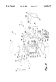
- FIG. 2 is an exploded view of a push button switch formed in accordance with the present invention showing the major elements of the switch;
- FIG. 3A is a side view of a push button switch formed in accordance with the present invention shown in the open circuit position and with the canister partially cut away for clarity;
- FIG. 3B is a rear-facing view of a push button switch formed in accordance with the present invention shown in the open circuit position with the canister partially cut away for clarity;
- FIG. 4A is a side view of a push button switch formed in accordance with the present invention shown in the open circuit position with the actuator of the switch fully translated within the canister and the canister partially cut away for clarity;
- FIG. 4B is an end view of a push button switch formed in accordance with the present invention with the switch in the open circuit position and showing the position of the hold down mechanism corresponding to the position of the actuator of FIG. 4A with the canister partially cut away for clarity;
- FIG. 5A is a side view of a push button switch formed in accordance with the present invention showing the switch in the closed circuit position
- FIG. 5B an end view of a push button switch formed in accordance with the present invention shown in the open circuit position with the canister partially cut away to illustrate the positioning of the hold down mechanism in the closed circuit position.
- FIGS. 1A-2 illustrate a preferred embodiment of a switch 20 constructed in accordance with the present invention.
- the switch 20 is designed to be used with a "pokehome" style termination header and can be installed in a variety of control panels (not shown) of a commercial vehicle, such as an airplane.
- switches 20 are used within the vehicle to actuate a variety of systems.
- switches may be configured as either a momentary switch, wherein the switch state is maintained as long as a load is applied to the switch cap, or an alternate action switch. While normally used in a substantially horizontal orientation, for ease of illustration and clarity, the switch 20 is shown in a vertical orientation. Therefore, the terminology vertical, upper, lower, etc., should be construed as descriptive, and not limiting.
- the switch 20 includes a well-known cap assembly 22, a switch module 24 and a switch can or housing 26.
- the switch 20 also includes a hold-down mechanism 28 attached to the switch module 24.
- the well known switch can 26 is a hollow and rectangularly shaped canister that is suitably extruded from a lightweight, high-strength material, such as aluminum.
- the switch can 26 is sized to slidably receive the switch module 24 therein.
- the switch module 24 may be secured within the switch can 26 by formed tab features on the switch can 26 or by well-known releasable fasteners (not shown), such as lugs pivotably attached to opposite sides of the switch module for selective engagement within corresponding holes (not shown) formed in the switch can 26.
- the cap assembly 22 is also a well-known assembly and is suitably injection-molded from a thermoplastic.
- the lower surface of the cap assembly 22 includes integrally formed and downwardly depending attachment arms 30a and 30b.
- the attachment arms 30a and 30b are horizontally aligned and includes an elongate slot 32 extending through the width of each arm 30a and 30b.
- Each slot 32 is sized to slidably receive a portion of the switch module 24 therein to selectively fasten the cap assembly 22 to the switch module 24, as is described in greater detail below.
- the switch module 24 includes a frame 40, a circuit assembly 42, a rocker 44, a tactile mechanism 46 and a foundation spring 48.
- the frame 40 is an inverted L-shaped member that is suitably injection-molded from a thermoplastic.
- the return of the frame 40 is bifurcated to define a pair of parallel arms 50a and 50b projecting normally from the spine thereof.
- Each arm 50a and 50b includes a rearwardly extending slot 52a and 52b.
- the slots 52a and 52b extend from the forward-facing surface of each arm 50a and 50b rearwardly for a predetermined distance towards the spine of the frame 40.
- the slots 52a and 52b are sized to slidably receive a slide pin 84, that slides through a portion of the rocker 44 therein to actuate the circuit assembly 42, as is described in greater detail below.
- the circuit assembly 42 includes a terminal plate 60, a plurality of flex circuits 62a-62c and a plurality of subminiature switches 64a-64d.
- the square-shaped terminal plate 60 is suitably injection-molded from a high-temperature plastic and includes a plurality of well-known terminal pins 66. Each terminal pin 66 is press-fitted into a vertically extending hole (not shown) formed in the terminal plate 60. Each pin 66 may be permanently attached to the terminal plate 60 by a well known method, such as soldering.
- the pins 66 are in electrical communication with at least one of the subminiature switches 64a-64d by the well known flex circuits 62a-62c.
- connection patterns between the pins 66 and the subminiature switches 64a-64d by the flex circuits 62a-62c are within the scope of the present invention.
- one end of the first flex circuit 62a is soldered to and in communication with a predetermined number of pins 66.
- the other end of the first flex circuit 62a is soldered to and is in communication with the subminiature switches 64a-64d.
- the second flex circuit 62b is soldered to and in communication with a predetermined number of the terminal pins 66, while and the other end thereof is soldered to and in communication with the subminiature switches 64a-64d.
- each flex circuit 62a-62c carries a level of current from the terminal pins 66 to at least one of the subminiature switches 64a-64d and/or the cap assembly 22 and back to the pins 66.
- a switch formed in accordance with the present invention includes a total of three flex circuits, a switch having more or fewer flex circuits, such as four or two flex circuits, is also within the scope of the present invention.
- flex circuits are preferred in establishing electrical communication between the terminal pins and the subminiature switches, other connection devices, such as ribbon cables, insulated individual leads or molded-in circuit traces, are also within the scope of the present invention.
- each subminiature switch 64a-64d has the capability of switching currents as low as 10 milliamps to a high of 8 amps.
- a switch includes single pull double-throw (SPDT), double break switches.
- Each subminiature switch 64a-64d includes a subminiature switch actuator 72.
- each subminiature switch actuator 72a-72d is a well known contact subminiature switch actuator, such as a plunger.
- contact subminiature switches 64a-64d are preferred, other current switching devices, such as a contactless switch, are also within the scope of the present invention.
- each actuator 72a-72d a sensor-type actuator, such as a Hall Effect sensor, is also within the scope of the present invention. Additionally, although four subminiature switches are preferred, more or fewer subminiature switches, such as five or one subminiature switch, are also within the scope of the present invention.
- the subminiature switches 64a-64d are orientated within the switch module 24, such that the axis of travel for each actuator plunger is substantially normal to the motion of the cap assembly 22. As a non-limiting example, the cap assembly 22 moves linearly in the vertical direction and, therefore, the axis of travel for the plunger is horizontal. Furthermore, the subminiature switches 64a-64d are orientated within the switch module 24, such that they are in contact with the rocker 44 for simultaneous actuation, as is described in greater detail below.
- the rocker 44 is an L-shaped member suitably injection-molded from a thermoplastic.
- the rocker 44 includes a forked upper end defining a pair of horizontally aligned arms 80a and 80b.
- the arms 80a and 80b project rearwardly and each includes an integrally formed semicircular protrusion 82a and 82b.
- the protrusions 82a and 82b extend outwardly in opposite directions from the sides of each arm 80a and 80b.
- the protrusions 82a and 82b are sized to be slidably received within the slots 32 of the cap assembly 22.
- the slots 32 and the protrusions 82a and 82b cooperate to smoothly transfer a linear load applied to the cap assembly 22 to the rocker 44 to change the state of the switch module 24, as is described in greater detail below.
- the rocker 44 is pivotably and slidably attached to the frame 40 by a pivot and slide pin 84.
- the pivot and slide pin 84 is a substantially cylindrical-shaped member and is slidably received within a pair of horizontally aligned holes 86a and 86b extending through the thickness of the arcuate section of the rocker 44.
- a retention spring 88 such as a torque spring, is pinned between the arms 80a and 80b of the rocker 44 by the pivot and slide pin 84.
- the retention spring 88 applies a substantially constant load to the rocker 44 to assist in biasing the lower end of the rocker 44 against the subminiature switch actuators 72a-72d.
- the inverted L-shaped foundation spring 48 is suitably formed from a high-strength spring material.
- the return of the foundation spring 48 is bifurcated to define rearwardly projecting attachment arms 100a and 100b.
- the attachment arms 100a and 100b may be fastened to the upper end of the frame 40 by well-known fasteners (not shown), such as screws, extending vertically through each arm 100a and 100b and into the upper portion of the frame 40.
- the foundation spring 48 is cantilevered to the frame 40.
- the arcuate portion extending between the attachment arms 100a and 100b in the spine of the foundation spring 48 has a predetermined amount of flexibility and preloads the foundation spring 48 when it is assembled to the circuit assembly 42.
- the tactile response of the switch 20 may be tuned by changing the stiffness of the arcuate portion to adjust the rigidity of the arcuate portion.
- the lower edge of the downwardly depending spine of the foundation spring 48 includes a lip 102.
- the lip 102 is sized to envelope the lower edge of the rocker 44 to provide a durable wear surface to extend the usable life of the rocker 44 due to engagement with the tactile mechanism 46, as is described in greater detail below.
- the tactile mechanism 46 includes a tactile base 110 and first and second tactile sliders 112a and 112b.
- the tactile base is suitably injection-molded from a thermoplastic and includes a planar support portion 114 and first and second tactile housings 116a and 116b integrally formed with one end of the support portion 114.
- the tactile housings 116a and 116b are horizontally aligned and project normally upward from one end of the support portion 114.
- Each tactile housing 116a and 116b includes a centrally located cavity 118a and 118b extending vertically therethrough.
- Each cavity 118a and 118b is sized to slidably receive one of the tactile sliders 112a and 112b therein.
- Each tactile slider 112a and 112b is suitably injection-molded from a thermoplastic and is substantially oval in shape.
- the upper surface of each tactile slider 112a and 112b is contoured to define a ramp 120a and 120b.
- the tactile sliders 112a and 112b are slidably received within the cavities 118a and 118b of the tactile base 110, such that the ramp angle projects upwardly from the tactile housings 116a and 116b.
- Each tactile sliders 112a and 112b are reciprocally mounted within the tactile housings 116a and 116b on a pair of coil compression springs 122a-122d.
- the support portion 114 of the tactile base 110 is sized to be received between the lower surfaces of the subminiature switches 64a-64d and the flex circuit 62a.
- the upper surfaces of the tactile sliders 112a and 112b project upwardly from the tactile base 110 and are sized and positioned to receive the lower ends of the rocker 44 and foundation spring 48 therein.
- the hold down mechanism 28 includes a heart guide wire 130 and a heart guide 132.
- the heart guide wire is a substantially V-shaped member sized to be received within a V-shaped recess 134 integrally formed in the rearwardly facing surface of the frame 40.
- the lower end of the heart guide wire 130 forms a circular loop that is sized to be received on a correspondingly shaped projection 136 integrally formed in the lower portion of the recess 134.
- One end of the heart guide wire 130 is received within a corresponding hole (not shown) formed in the upper end of the recess 134 to secure the heart guide wire 130 therein.
- the other free end of the heart guide wire 130 is sized for engagement with the heart guide 132 to selectively lock the switch 20 into a closed circuit position.
- the heart guide 132 is integrally formed with the rearwardly facing surface of the rocker 44 and is disposed substantially midway between the first and second arms 80a and 80b.
- the upper surface of the substantially heart-shaped heart guide 132 includes a centrally located yoke or saddle portion 138.
- the yoke portion 138 is sized to lockingly receive the free end of the heart guide wire 130 therein to selectively hold the switch 20 in the closed circuit condition, as described in greater detail below.
- the switch 20 has at least two distinct positions; an open circuit position and a closed circuit position.
- FIGS. 3A and 3B The open circuit position may be best understood by referring to FIGS. 3A and 3B.
- the lower end of the rocker 44 is displaced rearwardly against the subminiature switch actuator 72a-72d of each subminiature switch 64a-64d.
- the lower end of the rocker 44 is held against the subminiature switch actuator 72a-72d by the combination of the retention spring 88 and the tactile sliders 112a and 112b.
- the retention spring 88 biases the lower end of the rocker 44 rearwardly against the subminiature switch actuators 72a-72d.
- the lip 102 of the foundation spring 48 surrounds the lower end of the rocker 44 and engages the upper surface of the tactile sliders 112a and 112b, thereby limiting wear on the lower end of the rocker 44 due to frictional contact with the tactile sliders 112a and 112b.
- the free end of the heart guide wire 130 is positioned near the lower edge of the heart guide 132.
- FIGS. 4A and 4B Transition between the open circuit position and closed circuit position may be best understood by referring to FIGS. 4A and 4B.
- a downward linear load is applied to the upper surface of the cap assembly 22.
- the protrusions 82a and 82b of the rocker 44 slide rearwardly within the slot 32 of the attachment arms 30a and 30b.
- the pivot and slide pin 84 also slides rearwardly within the slots 52a and 52b of the arms 50a and 50b of the frame 40.
- the rocker 44 pivots about the contact point between the upper surface of the tactile sliders 112a and 112b and the lower edges of the rocker 44 and foundation spring 48.
- the lower end of the rocker 44 remains in contact with the subminiature switch actuators 72a-72d to maintain the switch 20 in the open circuit position.
- the rocker 44 pivots about a first pivot point defined at the lower edge portion of the rocker 44 and simultaneously translates within the frame 40 along an axis that is substantially parallel to the motion of each subminiature switch actuator 72a-72d.
- Motion of the heart guide wire 130 during this transition period may be best understood by referring to FIG. 4B.
- the cap assembly 22 translates downwardly within the switch can 26, the free end of the heart guide wire 130 engages the lower right hand side of the heart guide 132, causing the free end of the heart guide wire to slide in a counter-clockwise direction and upwardly along the heart guide 132.
- Transition to the closed circuit position may be best understood by referring to FIGS. 5A and 5B.
- the pivot and slide pin 84 is firmly seated against the closed ends of the slots 52a and 52b.
- the downward force causes a rotation of the rocker 44 within the frame 40 about a pivot point defined by a longitudinal axis extending between the ends of the pivot and slide pin 84.
- the rocker 44 rotates in a counter-clockwise direction, indicated by the arrow 140 about the pivot and slide pin 84.
- the rotation of the rocker 44 causes the lower end of the rocker 44 to pivot away from the subminiature switch actuators 72a-72d, thereby causing the subminiature switches 30 to actuate into the closed circuit position. Further, as the rocker 44 rotates about the slide and pivot pin 84, the lower end of the rocker 44 compresses the two tactile sliders 112a and 112b against the compression springs 122a-122d to provide a "snap" feel when the foundation spring 48 slides over the top of the ramp portion 120a and 120b of each tactile slider 112a and 112b. Further, because the rocker 44 is in simultaneous contact with all of the subminiature switch actuators 72a-72d, the rocker 44 prevents individual actuation of individual subminiature switch actuators.
- the free end is received within the yoke portion 138 of the heart guide 132 to selectively hold the switch 20 in the closed circuit position.
- the free end of the heart guide wire 130 was sliding along the right side of the heart guide 132 until it reached the upper end of the heart guide 132, wherein the heart guide wire 130 was free to snap, in a counter-clockwise direction, over to the yoke portion 138 and was received therein to selectively hold the switch 20 into the open circuit position.
- the cap assembly 22 is depressed a second time.
- the free end of the heart guide wire 130 moves in a counter-clockwise direction and out of locking contact with the yoke portion 138 of the heart guide 132.
- the retention spring 88 and the foundation spring 48 causes the lower end of the rocker 44 to slide down the tactile slides 112a and 112b and back into contact with the subminiature switch actuators 72a-72d, thereby returning the switch 20 back into the open circuit position as seen in FIGS. 3A and 3B.
- the previously described version of the present invention provides several advantages over switches currently available in the art.
- the orientation of the subminiature switch actuators within the subminiature switch can allow the end user to rearrange the external pin pattern to accommodate a multitude of connection pin configurations. This results in a switch that is convertible to accommodate multiple end user requirements and, therefore, is more versatile.
- the combination of the tactile mechanism 46 and the rocker 44 minimizes the possibility of non-simultaneous actuation of the subminiature switches.
- a switch formed in accordance with the present invention is also more reliable.
- a switch formed in accordance with the present invention has fewer parts and, therefore, is less costly to manufacture and again more reliable.
- a push button switch formed in accordance with the present invention is economical to produce, has a high reliability and produces the customary and anticipated tactile response while changing the state of the switch.
- a push button switch formed in accordance with the present invention incorporates many novel features and offers significant advantages over currently available switches. While presently preferred embodiments of the invention have been illustrated and described, it is to be understood that within the scope of the appended claims, various changes can be made therein without departing from the spirit of the invention.
Abstract
Description
Claims (37)
Priority Applications (1)
| Application Number | Priority Date | Filing Date | Title |
|---|---|---|---|
| US09/257,229 US6028279A (en) | 1998-02-27 | 1999-02-25 | Lighted push button switch |
Applications Claiming Priority (2)
| Application Number | Priority Date | Filing Date | Title |
|---|---|---|---|
| US7610998P | 1998-02-27 | 1998-02-27 | |
| US09/257,229 US6028279A (en) | 1998-02-27 | 1999-02-25 | Lighted push button switch |
Publications (1)
| Publication Number | Publication Date |
|---|---|
| US6028279A true US6028279A (en) | 2000-02-22 |
Family
ID=26757673
Family Applications (1)
| Application Number | Title | Priority Date | Filing Date |
|---|---|---|---|
| US09/257,229 Expired - Fee Related US6028279A (en) | 1998-02-27 | 1999-02-25 | Lighted push button switch |
Country Status (1)
| Country | Link |
|---|---|
| US (1) | US6028279A (en) |
Cited By (7)
| Publication number | Priority date | Publication date | Assignee | Title |
|---|---|---|---|---|
| US20040011635A1 (en) * | 2002-07-18 | 2004-01-22 | Adams Edward Roger | Electrical switch |
| US20040262140A1 (en) * | 2001-11-02 | 2004-12-30 | Marquardt Gmbh | Electric switch |
| US20060242105A1 (en) * | 2005-04-22 | 2006-10-26 | Microsoft Corporation | Pack URI scheme to identify and reference parts of a package |
| US20060242184A1 (en) * | 2005-04-22 | 2006-10-26 | Microsoft Corporation | Efficiently describing relationships between resources |
| US20070256048A1 (en) * | 2006-05-01 | 2007-11-01 | Microsoft Corporation | Loading application resources |
| US8970477B2 (en) | 2011-08-03 | 2015-03-03 | Blackberry Limited | Handheld device having retractable keypad assembly |
| EP2555081B1 (en) * | 2011-08-03 | 2016-08-17 | BlackBerry Limited | Handheld device having retractable keypad assembly |
Citations (18)
| Publication number | Priority date | Publication date | Assignee | Title |
|---|---|---|---|---|
| US3153714A (en) * | 1962-08-28 | 1964-10-20 | Illinois Tool Works | Alternate action snap action switch and lighted push button assembly |
| US3172296A (en) * | 1961-08-21 | 1965-03-09 | Coatrols Company Of America | Push button switch actuating mechanism |
| US3306992A (en) * | 1966-02-04 | 1967-02-28 | Teledyne Inc | Push-button switch actuating mechanism for indicator |
| US3340375A (en) * | 1965-10-07 | 1967-09-05 | Gen Electric | Electric circuit breaker with auxiliary switch means |
| US3345490A (en) * | 1964-07-14 | 1967-10-03 | Olympia Werke Ag | Manual switch actuator |
| US3776049A (en) * | 1971-05-19 | 1973-12-04 | Korry Mfg Co | Alternately released and detained reciprocable actuating mechanism |
| US3839607A (en) * | 1971-11-25 | 1974-10-01 | Seiko Koki Kk | Camera shutter power switch maintaining connection for cameras with electrically-operated shutters |
| US3866006A (en) * | 1972-08-23 | 1975-02-11 | Siemens Ag | Pushbutton switch with reciprocating cam |
| US4050670A (en) * | 1976-02-05 | 1977-09-27 | Masoneilan International, Inc. | Variable force actuator |
| US4227059A (en) * | 1978-06-19 | 1980-10-07 | Tokyo Shibaura Denki Kabushiki Kaisha | Driving mechanisms for vacuum circuit breakers |
| US4543459A (en) * | 1982-12-20 | 1985-09-24 | Hosiden Electronics Co., Ltd. | Small-sized switch |
| US4654494A (en) * | 1984-08-31 | 1987-03-31 | Sprecher & Schuh Ag | Actuating mechanism for an electrical switch with pressure contacts, especially for a vacuum switch |
| US4758694A (en) * | 1987-07-02 | 1988-07-19 | United Technologies Automotive, Inc. | Push-push type switch with tactile feedback |
| US4916269A (en) * | 1987-07-25 | 1990-04-10 | Swf Auto-Electric Gmbh | Push-button rocker electric switch |
| US5015811A (en) * | 1988-06-30 | 1991-05-14 | Omron Tateisi Electronics Co. | Snap-action pushbutton switch with click sound |
| US5057657A (en) * | 1990-07-23 | 1991-10-15 | Vedran Skulic | Electrical switch actuator mechanism |
| US5202607A (en) * | 1991-04-22 | 1993-04-13 | Gary Broyer | Adapter for fluorescent lamps |
| US5727675A (en) * | 1996-09-06 | 1998-03-17 | Eaton Corporation | Latching pushbutton switch assembly |
-
1999
- 1999-02-25 US US09/257,229 patent/US6028279A/en not_active Expired - Fee Related
Patent Citations (18)
| Publication number | Priority date | Publication date | Assignee | Title |
|---|---|---|---|---|
| US3172296A (en) * | 1961-08-21 | 1965-03-09 | Coatrols Company Of America | Push button switch actuating mechanism |
| US3153714A (en) * | 1962-08-28 | 1964-10-20 | Illinois Tool Works | Alternate action snap action switch and lighted push button assembly |
| US3345490A (en) * | 1964-07-14 | 1967-10-03 | Olympia Werke Ag | Manual switch actuator |
| US3340375A (en) * | 1965-10-07 | 1967-09-05 | Gen Electric | Electric circuit breaker with auxiliary switch means |
| US3306992A (en) * | 1966-02-04 | 1967-02-28 | Teledyne Inc | Push-button switch actuating mechanism for indicator |
| US3776049A (en) * | 1971-05-19 | 1973-12-04 | Korry Mfg Co | Alternately released and detained reciprocable actuating mechanism |
| US3839607A (en) * | 1971-11-25 | 1974-10-01 | Seiko Koki Kk | Camera shutter power switch maintaining connection for cameras with electrically-operated shutters |
| US3866006A (en) * | 1972-08-23 | 1975-02-11 | Siemens Ag | Pushbutton switch with reciprocating cam |
| US4050670A (en) * | 1976-02-05 | 1977-09-27 | Masoneilan International, Inc. | Variable force actuator |
| US4227059A (en) * | 1978-06-19 | 1980-10-07 | Tokyo Shibaura Denki Kabushiki Kaisha | Driving mechanisms for vacuum circuit breakers |
| US4543459A (en) * | 1982-12-20 | 1985-09-24 | Hosiden Electronics Co., Ltd. | Small-sized switch |
| US4654494A (en) * | 1984-08-31 | 1987-03-31 | Sprecher & Schuh Ag | Actuating mechanism for an electrical switch with pressure contacts, especially for a vacuum switch |
| US4758694A (en) * | 1987-07-02 | 1988-07-19 | United Technologies Automotive, Inc. | Push-push type switch with tactile feedback |
| US4916269A (en) * | 1987-07-25 | 1990-04-10 | Swf Auto-Electric Gmbh | Push-button rocker electric switch |
| US5015811A (en) * | 1988-06-30 | 1991-05-14 | Omron Tateisi Electronics Co. | Snap-action pushbutton switch with click sound |
| US5057657A (en) * | 1990-07-23 | 1991-10-15 | Vedran Skulic | Electrical switch actuator mechanism |
| US5202607A (en) * | 1991-04-22 | 1993-04-13 | Gary Broyer | Adapter for fluorescent lamps |
| US5727675A (en) * | 1996-09-06 | 1998-03-17 | Eaton Corporation | Latching pushbutton switch assembly |
Cited By (12)
| Publication number | Priority date | Publication date | Assignee | Title |
|---|---|---|---|---|
| US20040262140A1 (en) * | 2001-11-02 | 2004-12-30 | Marquardt Gmbh | Electric switch |
| US6965087B2 (en) * | 2001-11-02 | 2005-11-15 | Marquardt Gmbh | Electric switch |
| US20040011635A1 (en) * | 2002-07-18 | 2004-01-22 | Adams Edward Roger | Electrical switch |
| US6953905B2 (en) * | 2002-07-18 | 2005-10-11 | Maxera Llc | Electrical switch |
| US20060242105A1 (en) * | 2005-04-22 | 2006-10-26 | Microsoft Corporation | Pack URI scheme to identify and reference parts of a package |
| US20060242184A1 (en) * | 2005-04-22 | 2006-10-26 | Microsoft Corporation | Efficiently describing relationships between resources |
| US7437367B2 (en) * | 2005-04-22 | 2008-10-14 | Microsoft Corporation | Pack URI scheme to identify and reference parts of a package |
| US8135750B2 (en) | 2005-04-22 | 2012-03-13 | Microsoft Corporation | Efficiently describing relationships between resources |
| US20070256048A1 (en) * | 2006-05-01 | 2007-11-01 | Microsoft Corporation | Loading application resources |
| US7814498B2 (en) | 2006-05-01 | 2010-10-12 | Microsoft Corporation | Loading application resources |
| US8970477B2 (en) | 2011-08-03 | 2015-03-03 | Blackberry Limited | Handheld device having retractable keypad assembly |
| EP2555081B1 (en) * | 2011-08-03 | 2016-08-17 | BlackBerry Limited | Handheld device having retractable keypad assembly |
Similar Documents
| Publication | Publication Date | Title |
|---|---|---|
| US5668357A (en) | Seat combination switch | |
| US7105762B1 (en) | Rocker switch and actuator therefor | |
| US20030085110A1 (en) | Switch apparatus | |
| US5491311A (en) | Multifunction switch | |
| US6476697B2 (en) | Modular multi-phase contactor | |
| EP1898435B1 (en) | Switch and contact modules therefor | |
| US20020104748A1 (en) | Rocker switch | |
| EP0807033B1 (en) | Turn signal cancellation mechanism | |
| EP0083508B1 (en) | Contact structure for an alternate switch mechanism | |
| US6028279A (en) | Lighted push button switch | |
| US4376237A (en) | Vehicle turn signal switch actuator | |
| US5803240A (en) | Electric push-button switch | |
| US2900460A (en) | Electric switch | |
| US5120922A (en) | Momentary pushbutton slide switch | |
| US4393280A (en) | Electrical switching arrangement | |
| US6172314B1 (en) | Automotive combination switch | |
| JPH06185610A (en) | Shift lock device for automatic transmission | |
| CA1160273A (en) | Cam operated dual switch assembly | |
| US7528335B2 (en) | Light assembly for vehicle interiors | |
| US4758694A (en) | Push-push type switch with tactile feedback | |
| JPH0743901Y2 (en) | switch | |
| JPH08264075A (en) | Multifunction switch | |
| US20180114655A1 (en) | Electrical pushbutton snap switch with means for identifying the position of the pushbutton and/or of the driving member | |
| US5107085A (en) | Clustered push button switches having sheet metal conductors formed with contact tabs | |
| US7009131B2 (en) | Switch assembly |
Legal Events
| Date | Code | Title | Description |
|---|---|---|---|
| AS | Assignment |
Owner name: KORRY ELECTRONICS CO., WASHINGTON Free format text: ASSIGNMENT OF ASSIGNORS INTEREST;ASSIGNORS:SURYAN, MARK J.;GUNELL, GARY;REEL/FRAME:009794/0968 Effective date: 19990225 |
|
| CC | Certificate of correction | ||
| FPAY | Fee payment |
Year of fee payment: 4 |
|
| AS | Assignment |
Owner name: WACHOVIA BANK, NATIONAL ASSOCIATION, NORTH CAROLIN Free format text: SECURITY AGREEMENT;ASSIGNORS:ESTERLINE TECHNOLOGIES CORPORATION;ADVANCED INPUT DEVICES, INC.;ARMTEC COUNTERMAEASURES CO.;AND OTHERS;REEL/FRAME:014506/0608 Effective date: 20030611 |
|
| REMI | Maintenance fee reminder mailed | ||
| LAPS | Lapse for failure to pay maintenance fees | ||
| LAPS | Lapse for failure to pay maintenance fees |
Free format text: PATENT EXPIRED FOR FAILURE TO PAY MAINTENANCE FEES (ORIGINAL EVENT CODE: EXP.); ENTITY STATUS OF PATENT OWNER: LARGE ENTITY |
|
| STCH | Information on status: patent discontinuation |
Free format text: PATENT EXPIRED DUE TO NONPAYMENT OF MAINTENANCE FEES UNDER 37 CFR 1.362 |
|
| FP | Lapsed due to failure to pay maintenance fee |
Effective date: 20080222 |
|
| AS | Assignment |
Owner name: NORWICH AERO PRODUCTS, INC., NEW YORK Free format text: RELEASE BY SECURED PARTY;ASSIGNOR:WELLS FARGO BANK, NATIONAL ASSOCIATION, AS ADMINISTRATIVE AGENT FOR THE SECURED PARTIES AND SUCCESSOR TO WACHOVIA BANK, N.A.;REEL/FRAME:048610/0163 Effective date: 20190314 Owner name: BOYAR-SCHULTZ CORPORATION, MICHIGAN Free format text: RELEASE BY SECURED PARTY;ASSIGNOR:WELLS FARGO BANK, NATIONAL ASSOCIATION, AS ADMINISTRATIVE AGENT FOR THE SECURED PARTIES AND SUCCESSOR TO WACHOVIA BANK, N.A.;REEL/FRAME:048610/0163 Effective date: 20190314 Owner name: KORRY ELECTRONICS CO., WASHINGTON Free format text: RELEASE BY SECURED PARTY;ASSIGNOR:WELLS FARGO BANK, NATIONAL ASSOCIATION, AS ADMINISTRATIVE AGENT FOR THE SECURED PARTIES AND SUCCESSOR TO WACHOVIA BANK, N.A.;REEL/FRAME:048610/0163 Effective date: 20190314 Owner name: ADVANCED INPUT DEVICES, INC., IDAHO Free format text: RELEASE BY SECURED PARTY;ASSIGNOR:WELLS FARGO BANK, NATIONAL ASSOCIATION, AS ADMINISTRATIVE AGENT FOR THE SECURED PARTIES AND SUCCESSOR TO WACHOVIA BANK, N.A.;REEL/FRAME:048610/0163 Effective date: 20190314 Owner name: W.A. WHITNEY CO., ILLINOIS Free format text: RELEASE BY SECURED PARTY;ASSIGNOR:WELLS FARGO BANK, NATIONAL ASSOCIATION, AS ADMINISTRATIVE AGENT FOR THE SECURED PARTIES AND SUCCESSOR TO WACHOVIA BANK, N.A.;REEL/FRAME:048610/0163 Effective date: 20190314 Owner name: ARMTEC COUNTERMEASURES CO., NORTH CAROLINA Free format text: RELEASE BY SECURED PARTY;ASSIGNOR:WELLS FARGO BANK, NATIONAL ASSOCIATION, AS ADMINISTRATIVE AGENT FOR THE SECURED PARTIES AND SUCCESSOR TO WACHOVIA BANK, N.A.;REEL/FRAME:048610/0163 Effective date: 20190314 Owner name: ARMTEC DEFENSE PRODUCTS CO., CALIFORNIA Free format text: RELEASE BY SECURED PARTY;ASSIGNOR:WELLS FARGO BANK, NATIONAL ASSOCIATION, AS ADMINISTRATIVE AGENT FOR THE SECURED PARTIES AND SUCCESSOR TO WACHOVIA BANK, N.A.;REEL/FRAME:048610/0163 Effective date: 20190314 Owner name: BVR TECHNOLOGIES CO., ILLINOIS Free format text: RELEASE BY SECURED PARTY;ASSIGNOR:WELLS FARGO BANK, NATIONAL ASSOCIATION, AS ADMINISTRATIVE AGENT FOR THE SECURED PARTIES AND SUCCESSOR TO WACHOVIA BANK, N.A.;REEL/FRAME:048610/0163 Effective date: 20190314 Owner name: PRESSURE SYSTEMS, INC., VIRGINIA Free format text: RELEASE BY SECURED PARTY;ASSIGNOR:WELLS FARGO BANK, NATIONAL ASSOCIATION, AS ADMINISTRATIVE AGENT FOR THE SECURED PARTIES AND SUCCESSOR TO WACHOVIA BANK, N.A.;REEL/FRAME:048610/0163 Effective date: 20190314 Owner name: KIRKHILL-TA CO., CALIFORNIA Free format text: RELEASE BY SECURED PARTY;ASSIGNOR:WELLS FARGO BANK, NATIONAL ASSOCIATION, AS ADMINISTRATIVE AGENT FOR THE SECURED PARTIES AND SUCCESSOR TO WACHOVIA BANK, N.A.;REEL/FRAME:048610/0163 Effective date: 20190314 Owner name: EXCELLON AUTOMATION CO., CALIFORNIA Free format text: RELEASE BY SECURED PARTY;ASSIGNOR:WELLS FARGO BANK, NATIONAL ASSOCIATION, AS ADMINISTRATIVE AGENT FOR THE SECURED PARTIES AND SUCCESSOR TO WACHOVIA BANK, N.A.;REEL/FRAME:048610/0163 Effective date: 20190314 Owner name: MEMTRON TECHNOLOGIES CO., MICHIGAN Free format text: RELEASE BY SECURED PARTY;ASSIGNOR:WELLS FARGO BANK, NATIONAL ASSOCIATION, AS ADMINISTRATIVE AGENT FOR THE SECURED PARTIES AND SUCCESSOR TO WACHOVIA BANK, N.A.;REEL/FRAME:048610/0163 Effective date: 20190314 Owner name: FLUID REGULATORS CORPORATION, OHIO Free format text: RELEASE BY SECURED PARTY;ASSIGNOR:WELLS FARGO BANK, NATIONAL ASSOCIATION, AS ADMINISTRATIVE AGENT FOR THE SECURED PARTIES AND SUCCESSOR TO WACHOVIA BANK, N.A.;REEL/FRAME:048610/0163 Effective date: 20190314 |