US6009136A - Damped storage rack for nuclear fuel assemblies - Google Patents
Damped storage rack for nuclear fuel assemblies Download PDFInfo
- Publication number
- US6009136A US6009136A US09/020,981 US2098198A US6009136A US 6009136 A US6009136 A US 6009136A US 2098198 A US2098198 A US 2098198A US 6009136 A US6009136 A US 6009136A
- Authority
- US
- United States
- Prior art keywords
- support element
- corner
- adjacent
- cell
- tubular housing
- Prior art date
- Legal status (The legal status is an assumption and is not a legal conclusion. Google has not performed a legal analysis and makes no representation as to the accuracy of the status listed.)
- Expired - Lifetime
Links
- 230000000712 assembly Effects 0.000 title claims abstract description 24
- 238000000429 assembly Methods 0.000 title claims abstract description 24
- 239000003758 nuclear fuel Substances 0.000 title claims abstract description 17
- 238000013016 damping Methods 0.000 claims abstract description 22
- 210000004027 cell Anatomy 0.000 description 102
- 239000000446 fuel Substances 0.000 description 12
- 239000000463 material Substances 0.000 description 10
- 238000003466 welding Methods 0.000 description 7
- 229910001220 stainless steel Inorganic materials 0.000 description 5
- 239000010935 stainless steel Substances 0.000 description 5
- 239000003351 stiffener Substances 0.000 description 5
- 239000002574 poison Substances 0.000 description 4
- 231100000614 poison Toxicity 0.000 description 4
- XLYOFNOQVPJJNP-UHFFFAOYSA-N water Substances O XLYOFNOQVPJJNP-UHFFFAOYSA-N 0.000 description 4
- 239000011358 absorbing material Substances 0.000 description 3
- 238000005219 brazing Methods 0.000 description 3
- 238000001816 cooling Methods 0.000 description 3
- 239000011159 matrix material Substances 0.000 description 2
- 239000000853 adhesive Substances 0.000 description 1
- 230000001070 adhesive effect Effects 0.000 description 1
- XAGFODPZIPBFFR-UHFFFAOYSA-N aluminium Chemical compound [Al] XAGFODPZIPBFFR-UHFFFAOYSA-N 0.000 description 1
- 229910052782 aluminium Inorganic materials 0.000 description 1
- 210000002421 cell wall Anatomy 0.000 description 1
- 230000000295 complement effect Effects 0.000 description 1
- 230000002708 enhancing effect Effects 0.000 description 1
- 230000004907 flux Effects 0.000 description 1
- 238000009434 installation Methods 0.000 description 1
- 230000007774 longterm Effects 0.000 description 1
- 238000000034 method Methods 0.000 description 1
- NJPPVKZQTLUDBO-UHFFFAOYSA-N novaluron Chemical compound C1=C(Cl)C(OC(F)(F)C(OC(F)(F)F)F)=CC=C1NC(=O)NC(=O)C1=C(F)C=CC=C1F NJPPVKZQTLUDBO-UHFFFAOYSA-N 0.000 description 1
- 230000036316 preload Effects 0.000 description 1
- 230000002028 premature Effects 0.000 description 1
- 230000005855 radiation Effects 0.000 description 1
- 210000000352 storage cell Anatomy 0.000 description 1
- OORLZFUTLGXMEF-UHFFFAOYSA-N sulfentrazone Chemical compound O=C1N(C(F)F)C(C)=NN1C1=CC(NS(C)(=O)=O)=C(Cl)C=C1Cl OORLZFUTLGXMEF-UHFFFAOYSA-N 0.000 description 1
Images


Classifications
-
- G—PHYSICS
- G21—NUCLEAR PHYSICS; NUCLEAR ENGINEERING
- G21C—NUCLEAR REACTORS
- G21C19/00—Arrangements for treating, for handling, or for facilitating the handling of, fuel or other materials which are used within the reactor, e.g. within its pressure vessel
- G21C19/02—Details of handling arrangements
- G21C19/06—Magazines for holding fuel elements or control elements
- G21C19/07—Storage racks; Storage pools
-
- Y—GENERAL TAGGING OF NEW TECHNOLOGICAL DEVELOPMENTS; GENERAL TAGGING OF CROSS-SECTIONAL TECHNOLOGIES SPANNING OVER SEVERAL SECTIONS OF THE IPC; TECHNICAL SUBJECTS COVERED BY FORMER USPC CROSS-REFERENCE ART COLLECTIONS [XRACs] AND DIGESTS
- Y02—TECHNOLOGIES OR APPLICATIONS FOR MITIGATION OR ADAPTATION AGAINST CLIMATE CHANGE
- Y02E—REDUCTION OF GREENHOUSE GAS [GHG] EMISSIONS, RELATED TO ENERGY GENERATION, TRANSMISSION OR DISTRIBUTION
- Y02E30/00—Energy generation of nuclear origin
- Y02E30/30—Nuclear fission reactors
Definitions
- the invention relates to storage racks for storing nuclear fuel assemblies both during transport and during stationary storage.
- the racks are highly overdamped, enabling them to best withstand vibrations caused by seismic events or rough handling.
- Fuel for nuclear reactors is typically configured in the form of elongated fuel rods, which may be separate, stand-alone elements, or may be positioned within canisters.
- the fuel rods and rod/canister combinations are referred to as fuel assemblies.
- the fuel assemblies must be stored and/or transported with great care.
- storage racks are often used to support a plurality of fuel assemblies in a generally parallel, spaced-apart configuration, while maintaining the fuel assemblies in a subcritical array environment.
- the racks and the fuel assemblies contained therein may be completely submerged in a pool of water. The water provides cooling and additional shielding from nuclear radiation.
- the fuel storage racks of the prior art typically consist of an assembly of hollow cells, each defined by an array of elongated rectangular cross-section boxes or compartments.
- the boxes are typically made by forming sheets of stainless steel into elongated rectangular cross-section tubes (typically 9 inches square by 14 feet long and welding the corners of the elongated tubes together to form a matrix of elongated hollow cells, each adapted the receive a single fuel assembly.
- the tubes are joined at their corners to common rod segments that are located at various positions along the adjacent corners of the tubes.
- Exemplary storage racks are disclosed in U.S. Pat. Nos. 4,695,424, 4,857,263, 4,948,553, and 4,366,115.
- the tubes can be held in place by support bars that are welded or otherwise affixed to the top and bottom ends of each tube such as disclosed in commonly owned U.S. Pat. No. 5,384,813 entitled Highly Damped Storage Rack for Nuclear Fuel Assemblies, which is hereby incorporated by reference.
- a neutron absorbing (or "poison") material such as borated stainless steel, is typically welded or otherwise rigidly affixed to each of the walls of the boxes to absorb neutron flux from the fuel assemblies which may be positioned within the boxes, thereby avoiding an undesirable concentration of neutrons.
- the neutron absorbing material can preloaded against the walls of the tube as described in commonly owned U.S. Pat. No. 5,384,813 in order provide a coulomb damping function for improved resistance to vibration damage.
- Another object of the present invention is to provide an improved storage rack for nuclear fuel assemblies which is highly overdamped to enable the rack to withstand the vibration of seismic events or rough handling such as may be encountered during transportation of the rack.
- a further object is to provide an improved storage rack for nuclear fuel assemblies which may be easily and inexpensively manufactured.
- a rack structure for long term storage and/or transport of nuclear fuel assemblies.
- the storage rack includes an array of individual storage cells.
- the cells of the array are defined by a plurality of substantially round or polygonal cross-section, elongated cell housings, each extending along an elongated central axis, wherein the central axes are substantially parallel to each other.
- a support element includes a first portion adapted to be fixed to one of the cell housings and a second portion adapted to press or be biased against an adjacent cell housing.
- a stiffener wall may be welded to the adjacent cell housings along the perimeter of the rack to enclose the open cells along the perimeter.
- the cell housings and the stiffener walls are held in parallel alignment by support bars affixed thereto, for example by welding, at both the top and bottom ends of the array of cell housings.
- the support bars are positioned at the top and bottom ends between each row of cell housings and along the outer perimeter of the rack.
- the support bars may be recessed on one side or on alternating sides to provide positioning of the cell housings prior to affixation.
- a base plate is affixed to the bottom of the array to define the lower boundary of the respective cells and to support the fuel assemblies therein. To facilitate water flow for cooling of the nuclear fuel assemblies, the base plate may include holes at positions within each cell. Pedestals extending from the base plate may be used to raise the rack above a floor.
- the cell housings are substantially square in cross-section and positioned in alternate points of a rectangular grid configuration, so that each cell housing defines one cell in its interior and so that the outer walls of three or more adjacent cell housings define one cell.
- the first portion of the support element is adapted to be fastened to one corner of the cell housing and the second portion of the support element is adapted to engage and bear against the corner of an adjacent cell housing.
- the second portion of the support element is adapted to be pressed or biased against the outer wall of the adjacent cell housing.
- the resulting friction between the second portion and cell wall results in a coulomb damping function that is effective in damping vibration.
- the support elements also serve to align the cells during assembly and help to make the overall assembly more resistant to bowing by individual cell housings.
- the support elements can be fastened to one of the cell housings by welding, brazing or mechanical fastening.
- the second portion of the support element is merely adapted to engage and bear against an adjacent object or an adjacent cell housing.
- the second portion may also be further adapted to enhance the friction with the adjacent cell housing in order to improve coulomb damping performance.
- FIG. 1 is a plan view of a storage rack in accordance with one embodiment of the invention.
- FIG. 2 is an elevation view of the storage rack of FIG. 1.
- FIG. 3 is a plan view of a storage rack in accordance with an alternate embodiment of the invention.
- FIG. 4 is an elevation view of the storage rack of FIG. 2.
- FIG. 5A is a layout view
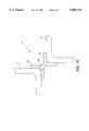
- FIG. 5B is a formal view of the support element in accordance with the present invention.
- Figure 5C is a top view of a support element installed between two cell housings in accordance with the present invention.
- FIG. 6 is a plan view of an alternative embodiment of the invention.
- FIGS. 1-4 show two embodiments of a storage rack 10 of the invention, which forms a close packed array, 3 rows by 5 columns of elongated cells C1-C15.
- the odd numbered or primary cells C1, C3, C5, C7, C9, C11, C13, C15 are formed from rectangular cell housings 3 which extend along housing axes 3'.
- the even numbered or secondary cells C2, C4, C6, C8, C10, C12, C14 are formed by the walls of the surrounding cells. It is noted that the secondary cells along the perimeter of the array C2, C4, C6, C10, C12, C14 are not completely surrounded by primary cells. If it is necessary that one of these secondary cells is to be utilized, a stiffener wall 3A is inserted substantially flush with exterior walls of the adjacent primary cell housings to completely enclose the secondary cell as shown in FIG. 3.
- the individual cell housings 3 are assembled into a rack assembly by fixturing the individual cell housings 3 and welding adjacent corners of the cell housings 3 to rod segments 5.
- the rod segments 5 can have various shapes and sizes including round, square, triangular or wedge.
- the major tolerance variation in the longitudinal bow of the cell housings 3 is from approximately ⁇ 1/8 inches to ⁇ 3/16 inches and thus the rod segments 5 can vary in diameter from zero to 5/16 inches in diameter.
- the stiffener wall 3A if required, can be welded to the adjacent cell housings 3.
- the individual cell housings 3 and the stiffener walls 3A are held in parallel alignment by upper and lower support bars 1, 7, and 8 which extend transverse to the longitudinal axis of the cell housings 3.
- the support bars 1, 7 and 8 are located between each of the rows of cells and along the perimeter of the array as shown in FIG. 3. Support bars 1, 7 and 8 are provided at both the top and bottom end portions of the rack.
- the cell housings are held in parallel alignment by welding the individual cell housings 3 to the upper and lower support bars 1, 7 and 8.
- the support bars also add strength to the upper and lower ends of the cell housings to resist damage during inserting and removal of the nuclear fuel rod assemblies.
- a base plate 2 is welded to the bottom of the rack to close the bottom of the cells and support the nuclear fuel assemblies.
- the base plate 2 may also be provided with holes 12 (shown in FIGS. 1 and 3) at locations within each cell and pedestal feet 9 to facilitate the flow of water for enhanced cooling.
- Each cell housing 3 is an elongated tube, typically having a square or rectangular cross-section.
- the housing is constructed from suitable material, for example, 0.090 inch thick stainless steel tubing.
- the tubes are square in cross-section, approximately nine inches along each side and 14 feet long.
- Each outer surface of the housing is planar, to which is applied, with or without a preload force, an elongated slab 4 constructed of a damping material.
- This damping material can also be a neutron absorbing material, such as borated stainless steel, borated aluminum, boral (such as manufactured by Brooks & Perkins, Minneapolis, Minn.), or other neutron absorbing materials may be used.
- the damping material can be fixed to outside of the cell housings (such as by welding or brazing) or the damping material can be preloaded against the outer surface by retainer clips (not shown) which are welded to the outside of the housings along the perimeter of each surface as disclosed in commonly owned U.S. Pat. No. 5,384,813.
- each of the cell housings 3 can include one or more support elements 14 fixed at one corner on the outside of the cell housing 3 which are adapted to bear against the adjacent corner of an adjacent cell housing 3.
- the support element 14 serves to align the cell housings 3 during assembly and further functions to help the cell housing resist bowing after assembly.
- the portion of the support element that bears against the adjacent corner of the adjacent cell housing 3 can provide coulomb damping of vibration in the individual cell housings 3.
- FIG. 5A shows a diagrammatic layout view of a support element 14 (prior to forming) in accordance with one embodiment of the present invention.
- Support element 14 includes a first portion adapted to engage a first cell housing and at least one second portion adapted to bear against an adjacent cell housing.
- the support element 14 has a second portion which includes upper tabs 22 and a third portion which includes lower tabs 24.
- the upper tabs 22 and the lower tabs 24 are connected by upper arm 28 and lower arm 30, respectively, to the first portion which includes central tabs 26.
- the support element 14 is formed from 0.060 inch thick stainless steel that is approximately 3 inches long.
- the upper and lower tabs 22 and 24 are approximately 0.25 inches wide and extend from approximately 0.22 inches from the upper and lower arms 28, 30.
- the central tabs 26 are approximately 0.50 inches wide and extend from approximately 0.22 inches from the upper and lower arms 28, 30.
- the width of each of the upper and lower arms 28, 30 is approximately 0.180 inches.
- FIGS. 5B and 5C shows diagrammatic views of a formed support element 14 in accordance with one embodiment of the present invention.
- Upper and lower tabs 22 and 24 are bent, toward the same side of the upper and lower arms 28, 30, to a 90 degree angle to form an inside corner that is adapted to engage the outside corner of an adjacent cell housing 3.
- the central tabs 26 are bent, toward the opposite side from the upper and lower tabs 22, 24, to a 90 degree angle to form an inside corner that is adapted to engage and be fastened the outside corner of a cell housing 3.
- the central tabs 26 can be fastened to the cell housing 3 by any fastening method including welding, brazing or the use of mechanical fasteners or adhesives.
- Upper and lower tabs 22, 24 form pads that bear against the adjacent corner of an adjacent cell housing.
- the interface between the upper and lower tabs 22, 24 and the outer surfaces that form the adjacent corner of the adjacent cell housing is such that they establish a coulomb damping function that damps vibration in the storage rack.
- the upper and lower arms 28, 30 preferably act as leaf springs to press or bias the upper and lower tabs 22, 24 respectively against the adjacent corner of the adjacent cell housing 3.
- the support elements 14 facilitated alignment of the cell housings 3 in the array during assembly and serve to maintain the array integrity by opposing bowing of individual cell housings.
- any tendency of an individual cell housing to bow is opposed by the support elements in contact therewith and the adjacent cell housings which distribute the load due to bowing over the adjacent cell housings.
- One or both of the upper and lower arms 28, 30 can be curved or formed prior to installation to enhance the bias force of the pads of upper and lower tabs 22, 24 against the adjacent cell housing.
- lower arm 30 is curved or bent away from central tab 26 in order to increase the pressure that lower tab 24 applies on the adjacent cell housing after it is installed.
- FIG. 5C shows a top view of a support element 14 installed between adjacent corners of two cell housings 3 and 3'.
- Tabs 26 of support element 14 are fastened the adjacent sides that form the corner of cell housing 3 and tabs 22 bear against the adjacent sides that form the corner of cell housing 3'.
- two support elements are installed between adjacent cell housings.
- the two support elements are fastened at positions that are equally spaced from the ends of the cell housings and from each other.
- each cell housing is fabricated with two support elements on each of two adjacent corners and each of the cell housings is positioned in the array that forms the storage rack wherein the two corners that carry the support elements are oriented in the same direction.
- FIG. 6 shows a top view of storage rack 100 in accordance with an alternative embodiment of the invention.
- the cell housings 103 are hexagonal in cross-section as opposed rectangular or square and the sides of the cell housings, as opposed to the corners of the cell housings are adjacent to one another.
- the cell housings 3, 103 can have any cross-sectional shape including round or circular cross-sections and polygonal cross-sections.
- one or more support elements 114 are disposed between two adjacent cell housings. In this embodiment, the support element 114 is formed substantially as shown in FIG. 5A and the tabs are not bent or formed.
- the central tabs 126 are fastened to one side of cell housing 103 and the upper tab 122 and the lower tab (not shown) are pressed or biased against an adjacent side of cell housing 103'.
- the support elements 114 provide a coulomb damping function to reduce vibration and help align the cell housings in the matrix as described above.
- the features (e.g. a side or corner) of one cell may be adjacent to a different feature of an adjacent cell.
- the first portion of the support element is adapted to conform to the surface contour and engage the feature or portion of the cell housing that it is to be fixed to.
- the first portion is conformed with a complementary inside corner shape.
- the first portion is adapted to be fixed to a flat surface or a curved surface, the first portion is substantially flat or curved, respectively to facilitate engagement.
- the second portion is adapted to conform to the surface contour of the feature to which it is to engage.
- either the second portion or the feature (or both) may be further adapted to change the friction between them in order to change the coulomb damping performance.
- the surface of the second portion or the feature may be textured and/or coated and/or plated with a material to change the frictional characteristics and the coulomb damping performance.
- a friction enhancing pad may be fixed to either the second portion or the feature (or both).
- the cell housings 3, 103 can be provided with neutron absorbing or "poison" material 4, 104.
- the poison material 4, 104 can be either fixed to the cell housing or the poison material 4, 104 can be held in place by clips or a cover plate as disclosed in commonly owned U.S. Pat. No. 5,348,813.
- the number, size and configuration of support elements 14, 114 can be readily determined as a function of the desired level of vibration damping.
- corner bearing or side bearing support elements one of ordinary skill in the art will appreciate that both corner bearing and side bearing support elements can be used in the same rack assembly, depending upon the level of vibration damping required.
Abstract
Description
Claims (19)
Priority Applications (1)
| Application Number | Priority Date | Filing Date | Title |
|---|---|---|---|
| US09/020,981 US6009136A (en) | 1998-02-09 | 1998-02-09 | Damped storage rack for nuclear fuel assemblies |
Applications Claiming Priority (1)
| Application Number | Priority Date | Filing Date | Title |
|---|---|---|---|
| US09/020,981 US6009136A (en) | 1998-02-09 | 1998-02-09 | Damped storage rack for nuclear fuel assemblies |
Publications (1)
| Publication Number | Publication Date |
|---|---|
| US6009136A true US6009136A (en) | 1999-12-28 |
Family
ID=21801683
Family Applications (1)
| Application Number | Title | Priority Date | Filing Date |
|---|---|---|---|
| US09/020,981 Expired - Lifetime US6009136A (en) | 1998-02-09 | 1998-02-09 | Damped storage rack for nuclear fuel assemblies |
Country Status (1)
| Country | Link |
|---|---|
| US (1) | US6009136A (en) |
Cited By (7)
| Publication number | Priority date | Publication date | Assignee | Title |
|---|---|---|---|---|
| US20050117687A1 (en) * | 2003-10-10 | 2005-06-02 | George Carver | Container and method for storing or transporting spent nuclear fuel |
| KR100844440B1 (en) | 2006-12-27 | 2008-07-07 | 한국전력기술 주식회사 | Impact absorbing insert for CEDM Seismic Plates |
| US7780833B2 (en) | 2005-07-26 | 2010-08-24 | John Hawkins | Electrochemical ion exchange with textured membranes and cartridge |
| US7959780B2 (en) | 2004-07-26 | 2011-06-14 | Emporia Capital Funding Llc | Textured ion exchange membranes |
| US20120126150A1 (en) * | 2009-07-31 | 2012-05-24 | Mitsubishi Heavy Industries, Ltd. | Transportation container of fuel assembly |
| US20130070885A1 (en) * | 2006-09-06 | 2013-03-21 | Krishna P. Singh | Canister apparatus and basket for transporting, storing and/or supporting spent nuclear fuel |
| US8562803B2 (en) | 2005-10-06 | 2013-10-22 | Pionetics Corporation | Electrochemical ion exchange treatment of fluids |
Citations (13)
| Publication number | Priority date | Publication date | Assignee | Title |
|---|---|---|---|---|
| US31661A (en) * | 1861-03-12 | Cotton-cleaner | ||
| US3900116A (en) * | 1972-09-05 | 1975-08-19 | Exxon Nuclear Co Inc | Fuel element shipping shim for nuclear reactor |
| US4042828A (en) * | 1975-11-17 | 1977-08-16 | Nuclear Services Corporation | Rack for nuclear fuel elements |
| US4177386A (en) * | 1978-05-26 | 1979-12-04 | Robbins Thomas R | Method and apparatus for storing nuclear fuel assemblies in maximum density racks |
| US4187433A (en) * | 1977-08-05 | 1980-02-05 | Automation Industries, Inc. | High density fuel storage rack |
| US4230144A (en) * | 1979-06-06 | 1980-10-28 | Hayward Tyler Pump Company | Seismic support for pendantly suspended body |
| US4342620A (en) * | 1980-04-21 | 1982-08-03 | Combustion Engineering, Inc. | Box insert for storage of spent nuclear fuel assembly |
| US4366115A (en) * | 1979-08-07 | 1982-12-28 | Schlumpf Raymond Jacques | Storage rack for assemblages of nuclear fuel elements |
| US4695424A (en) * | 1985-10-23 | 1987-09-22 | Westinghouse Electric Corp. | Cell for a spent nuclear fuel rack |
| US4800283A (en) * | 1987-05-01 | 1989-01-24 | Westinghouse Electric Corp. | Shock-absorbing and heat conductive basket for use in a fuel rod transportation cask |
| US4857263A (en) * | 1983-03-01 | 1989-08-15 | Westinghouse Electric Corp. | Storage of spent nuclear fuel |
| US4948553A (en) * | 1983-03-01 | 1990-08-14 | Westinghouse Electric Corp. | Method of making a rack for the storage of spent nuclear fuel |
| US5384813A (en) * | 1993-03-05 | 1995-01-24 | Ionics, Inc. | Highly damped storage rack for nuclear fuel assemblies |
-
1998
- 1998-02-09 US US09/020,981 patent/US6009136A/en not_active Expired - Lifetime
Patent Citations (13)
| Publication number | Priority date | Publication date | Assignee | Title |
|---|---|---|---|---|
| US31661A (en) * | 1861-03-12 | Cotton-cleaner | ||
| US3900116A (en) * | 1972-09-05 | 1975-08-19 | Exxon Nuclear Co Inc | Fuel element shipping shim for nuclear reactor |
| US4042828A (en) * | 1975-11-17 | 1977-08-16 | Nuclear Services Corporation | Rack for nuclear fuel elements |
| US4187433A (en) * | 1977-08-05 | 1980-02-05 | Automation Industries, Inc. | High density fuel storage rack |
| US4177386A (en) * | 1978-05-26 | 1979-12-04 | Robbins Thomas R | Method and apparatus for storing nuclear fuel assemblies in maximum density racks |
| US4230144A (en) * | 1979-06-06 | 1980-10-28 | Hayward Tyler Pump Company | Seismic support for pendantly suspended body |
| US4366115A (en) * | 1979-08-07 | 1982-12-28 | Schlumpf Raymond Jacques | Storage rack for assemblages of nuclear fuel elements |
| US4342620A (en) * | 1980-04-21 | 1982-08-03 | Combustion Engineering, Inc. | Box insert for storage of spent nuclear fuel assembly |
| US4857263A (en) * | 1983-03-01 | 1989-08-15 | Westinghouse Electric Corp. | Storage of spent nuclear fuel |
| US4948553A (en) * | 1983-03-01 | 1990-08-14 | Westinghouse Electric Corp. | Method of making a rack for the storage of spent nuclear fuel |
| US4695424A (en) * | 1985-10-23 | 1987-09-22 | Westinghouse Electric Corp. | Cell for a spent nuclear fuel rack |
| US4800283A (en) * | 1987-05-01 | 1989-01-24 | Westinghouse Electric Corp. | Shock-absorbing and heat conductive basket for use in a fuel rod transportation cask |
| US5384813A (en) * | 1993-03-05 | 1995-01-24 | Ionics, Inc. | Highly damped storage rack for nuclear fuel assemblies |
Cited By (14)
| Publication number | Priority date | Publication date | Assignee | Title |
|---|---|---|---|---|
| WO2005035373A3 (en) * | 2003-10-10 | 2006-09-08 | Nac International Inc | Container and method for storing or transporting spent nuclear fuel |
| US8630384B2 (en) * | 2003-10-10 | 2014-01-14 | Nac International, Inc. | Container and method for storing or transporting spent nuclear fuel |
| US20050117687A1 (en) * | 2003-10-10 | 2005-06-02 | George Carver | Container and method for storing or transporting spent nuclear fuel |
| US7959780B2 (en) | 2004-07-26 | 2011-06-14 | Emporia Capital Funding Llc | Textured ion exchange membranes |
| US7780833B2 (en) | 2005-07-26 | 2010-08-24 | John Hawkins | Electrochemical ion exchange with textured membranes and cartridge |
| US8293085B2 (en) | 2005-07-26 | 2012-10-23 | Pionetics Corporation | Cartridge having textured membrane |
| US8562803B2 (en) | 2005-10-06 | 2013-10-22 | Pionetics Corporation | Electrochemical ion exchange treatment of fluids |
| US9090493B2 (en) | 2005-10-06 | 2015-07-28 | Pionetics Corporation | Electrochemical ion exchange treatment of fluids |
| US20130070885A1 (en) * | 2006-09-06 | 2013-03-21 | Krishna P. Singh | Canister apparatus and basket for transporting, storing and/or supporting spent nuclear fuel |
| US8929504B2 (en) * | 2006-09-06 | 2015-01-06 | Holtec International, Inc. | Canister apparatus and basket for transporting, storing and/or supporting spent nuclear fuel |
| US10026514B2 (en) * | 2006-09-06 | 2018-07-17 | Holtec International, Inc. | Canister apparatus and basket for transporting, storing and/or supporting spent nuclear fuel |
| KR100844440B1 (en) | 2006-12-27 | 2008-07-07 | 한국전력기술 주식회사 | Impact absorbing insert for CEDM Seismic Plates |
| US20120126150A1 (en) * | 2009-07-31 | 2012-05-24 | Mitsubishi Heavy Industries, Ltd. | Transportation container of fuel assembly |
| US9117555B2 (en) * | 2009-07-31 | 2015-08-25 | Mitsubishi Heavy Industries, Ltd. | Transportation container of fuel assembly |
Similar Documents
| Publication | Publication Date | Title |
|---|---|---|
| US5384813A (en) | Highly damped storage rack for nuclear fuel assemblies | |
| JP5196620B2 (en) | Radioactive material storage cage | |
| US4039842A (en) | Fuel storage rack | |
| US8630384B2 (en) | Container and method for storing or transporting spent nuclear fuel | |
| US20180247720A1 (en) | High earthquake-resistant fuel storage rack system for fuel pools in nuclear plants | |
| US8009789B2 (en) | Storage device for storing and transporting nuclear fuel assemblies | |
| KR830001009B1 (en) | Rack for storing fuel assemblies | |
| JP2006162595A (en) | Storage structure | |
| US6009136A (en) | Damped storage rack for nuclear fuel assemblies | |
| US20120082285A1 (en) | Spent fuel storage rack | |
| US11670430B2 (en) | Nuclear fuel storage system with integral shimming | |
| US4305787A (en) | Storage rack for spent radioactive fuel | |
| US20170372806A1 (en) | Self-aligning neutron absorbing apparatus for reactivity mitigation in nuclear fuel storage systems | |
| US4248668A (en) | Storage module for nuclear fuel assemblies | |
| US4695424A (en) | Cell for a spent nuclear fuel rack | |
| JP5517656B2 (en) | Fuel storage rack group and fuel storage equipment | |
| US4948553A (en) | Method of making a rack for the storage of spent nuclear fuel | |
| KR910005107B1 (en) | Storage of spent nuclear fuel | |
| JP2001183491A (en) | Spent fuel storage rack | |
| JP7161960B2 (en) | Storage cell, nuclear fuel storage rack, storage cell manufacturing method, and nuclear fuel storage rack manufacturing method | |
| JP7178280B2 (en) | Restraint device, rack for nuclear fuel storage, and method for restraining rack for nuclear fuel storage | |
| JP2008281437A (en) | Fuel storage structure of spent fuel cask | |
| JPS5812158Y2 (en) | Spent fuel storage rack | |
| JP6809992B2 (en) | Cask mount, cask storage structure, and cask storage method | |
| JP3080954B1 (en) | Spent fuel storage rack |
Legal Events
| Date | Code | Title | Description |
|---|---|---|---|
| AS | Assignment |
Owner name: IONICS, INCORPORATED, MASSACHUSETTS Free format text: ASSIGNMENT OF ASSIGNORS INTEREST;ASSIGNORS:LOFTIS, JOSEPH M.;WACHTER, WILLIAM J.;REEL/FRAME:008984/0629 Effective date: 19980130 |
|
| STCF | Information on status: patent grant |
Free format text: PATENTED CASE |
|
| FPAY | Fee payment |
Year of fee payment: 4 |
|
| AS | Assignment |
Owner name: UBS AG, STAMFORD BRANCH AS COLLATERAL AGENT, CONNE Free format text: ;ASSIGNOR:IONICS, INCORPORATED;REEL/FRAME:015000/0654 Effective date: 20040213 Owner name: UBS AG, STAMFORD BRANCH AS COLLATERAL AGENT,CONNEC Free format text: SEE 015083/0722 CORRECTION OF REC. DATE;ASSIGNOR:IONICS, INCORPORATED;REEL/FRAME:015000/0654 Effective date: 20040213 |
|
| AS | Assignment |
Owner name: UBS AG, STAMFORD BRANCH AS COLLATERAL AGENT, CONNE Free format text: SECURITY AGREEMENT;ASSIGNOR:IONICS, INCORPORATED;REEL/FRAME:015083/0722 Effective date: 20040213 Owner name: UBS AG, STAMFORD BRANCH AS COLLATERAL AGENT,CONNEC Free format text: SECURITY AGREEMENT;ASSIGNOR:IONICS, INCORPORATED;REEL/FRAME:015083/0722 Effective date: 20040213 |
|
| FPAY | Fee payment |
Year of fee payment: 8 |
|
| SULP | Surcharge for late payment |
Year of fee payment: 7 |
|
| FPAY | Fee payment |
Year of fee payment: 12 |