US5972004A - Wire fasteners for use in minimally invasive surgery and apparatus and methods for handling those fasteners - Google Patents
Wire fasteners for use in minimally invasive surgery and apparatus and methods for handling those fasteners Download PDFInfo
- Publication number
- US5972004A US5972004A US09/026,671 US2667198A US5972004A US 5972004 A US5972004 A US 5972004A US 2667198 A US2667198 A US 2667198A US 5972004 A US5972004 A US 5972004A
- Authority
- US
- United States
- Prior art keywords
- fastener
- tool
- leg
- legs
- fasteners
- Prior art date
- Legal status (The legal status is an assumption and is not a legal conclusion. Google has not performed a legal analysis and makes no representation as to the accuracy of the status listed.)
- Expired - Lifetime
Links
Images


Classifications
-
- A—HUMAN NECESSITIES
- A61—MEDICAL OR VETERINARY SCIENCE; HYGIENE
- A61B—DIAGNOSIS; SURGERY; IDENTIFICATION
- A61B17/00—Surgical instruments, devices or methods, e.g. tourniquets
- A61B17/04—Surgical instruments, devices or methods, e.g. tourniquets for suturing wounds; Holders or packages for needles or suture materials
- A61B17/0469—Suturing instruments for use in minimally invasive surgery, e.g. endoscopic surgery
-
- A—HUMAN NECESSITIES
- A61—MEDICAL OR VETERINARY SCIENCE; HYGIENE
- A61B—DIAGNOSIS; SURGERY; IDENTIFICATION
- A61B17/00—Surgical instruments, devices or methods, e.g. tourniquets
- A61B17/064—Surgical staples, i.e. penetrating the tissue
- A61B17/0644—Surgical staples, i.e. penetrating the tissue penetrating the tissue, deformable to closed position
-
- A—HUMAN NECESSITIES
- A61—MEDICAL OR VETERINARY SCIENCE; HYGIENE
- A61B—DIAGNOSIS; SURGERY; IDENTIFICATION
- A61B17/00—Surgical instruments, devices or methods, e.g. tourniquets
- A61B17/068—Surgical staplers, e.g. containing multiple staples or clamps
- A61B17/0682—Surgical staplers, e.g. containing multiple staples or clamps for applying U-shaped staples or clamps, e.g. without a forming anvil
- A61B17/0684—Surgical staplers, e.g. containing multiple staples or clamps for applying U-shaped staples or clamps, e.g. without a forming anvil having a forming anvil staying above the tissue during stapling
-
- A—HUMAN NECESSITIES
- A61—MEDICAL OR VETERINARY SCIENCE; HYGIENE
- A61B—DIAGNOSIS; SURGERY; IDENTIFICATION
- A61B17/00—Surgical instruments, devices or methods, e.g. tourniquets
- A61B17/068—Surgical staplers, e.g. containing multiple staples or clamps
- A61B17/072—Surgical staplers, e.g. containing multiple staples or clamps for applying a row of staples in a single action, e.g. the staples being applied simultaneously
-
- A—HUMAN NECESSITIES
- A61—MEDICAL OR VETERINARY SCIENCE; HYGIENE
- A61F—FILTERS IMPLANTABLE INTO BLOOD VESSELS; PROSTHESES; DEVICES PROVIDING PATENCY TO, OR PREVENTING COLLAPSING OF, TUBULAR STRUCTURES OF THE BODY, e.g. STENTS; ORTHOPAEDIC, NURSING OR CONTRACEPTIVE DEVICES; FOMENTATION; TREATMENT OR PROTECTION OF EYES OR EARS; BANDAGES, DRESSINGS OR ABSORBENT PADS; FIRST-AID KITS
- A61F2/00—Filters implantable into blood vessels; Prostheses, i.e. artificial substitutes or replacements for parts of the body; Appliances for connecting them with the body; Devices providing patency to, or preventing collapsing of, tubular structures of the body, e.g. stents
- A61F2/02—Prostheses implantable into the body
- A61F2/24—Heart valves ; Vascular valves, e.g. venous valves; Heart implants, e.g. passive devices for improving the function of the native valve or the heart muscle; Transmyocardial revascularisation [TMR] devices; Valves implantable in the body
- A61F2/2409—Support rings therefor, e.g. for connecting valves to tissue
-
- A—HUMAN NECESSITIES
- A61—MEDICAL OR VETERINARY SCIENCE; HYGIENE
- A61F—FILTERS IMPLANTABLE INTO BLOOD VESSELS; PROSTHESES; DEVICES PROVIDING PATENCY TO, OR PREVENTING COLLAPSING OF, TUBULAR STRUCTURES OF THE BODY, e.g. STENTS; ORTHOPAEDIC, NURSING OR CONTRACEPTIVE DEVICES; FOMENTATION; TREATMENT OR PROTECTION OF EYES OR EARS; BANDAGES, DRESSINGS OR ABSORBENT PADS; FIRST-AID KITS
- A61F2/00—Filters implantable into blood vessels; Prostheses, i.e. artificial substitutes or replacements for parts of the body; Appliances for connecting them with the body; Devices providing patency to, or preventing collapsing of, tubular structures of the body, e.g. stents
- A61F2/02—Prostheses implantable into the body
- A61F2/24—Heart valves ; Vascular valves, e.g. venous valves; Heart implants, e.g. passive devices for improving the function of the native valve or the heart muscle; Transmyocardial revascularisation [TMR] devices; Valves implantable in the body
- A61F2/2427—Devices for manipulating or deploying heart valves during implantation
-
- A—HUMAN NECESSITIES
- A61—MEDICAL OR VETERINARY SCIENCE; HYGIENE
- A61B—DIAGNOSIS; SURGERY; IDENTIFICATION
- A61B17/00—Surgical instruments, devices or methods, e.g. tourniquets
- A61B17/04—Surgical instruments, devices or methods, e.g. tourniquets for suturing wounds; Holders or packages for needles or suture materials
- A61B17/0401—Suture anchors, buttons or pledgets, i.e. means for attaching sutures to bone, cartilage or soft tissue; Instruments for applying or removing suture anchors
-
- A—HUMAN NECESSITIES
- A61—MEDICAL OR VETERINARY SCIENCE; HYGIENE
- A61B—DIAGNOSIS; SURGERY; IDENTIFICATION
- A61B17/00—Surgical instruments, devices or methods, e.g. tourniquets
- A61B17/04—Surgical instruments, devices or methods, e.g. tourniquets for suturing wounds; Holders or packages for needles or suture materials
- A61B17/0467—Instruments for cutting sutures
-
- A—HUMAN NECESSITIES
- A61—MEDICAL OR VETERINARY SCIENCE; HYGIENE
- A61B—DIAGNOSIS; SURGERY; IDENTIFICATION
- A61B17/00—Surgical instruments, devices or methods, e.g. tourniquets
- A61B17/04—Surgical instruments, devices or methods, e.g. tourniquets for suturing wounds; Holders or packages for needles or suture materials
- A61B17/0487—Suture clamps, clips or locks, e.g. for replacing suture knots; Instruments for applying or removing suture clamps, clips or locks
-
- A—HUMAN NECESSITIES
- A61—MEDICAL OR VETERINARY SCIENCE; HYGIENE
- A61B—DIAGNOSIS; SURGERY; IDENTIFICATION
- A61B17/00—Surgical instruments, devices or methods, e.g. tourniquets
- A61B17/064—Surgical staples, i.e. penetrating the tissue
-
- A—HUMAN NECESSITIES
- A61—MEDICAL OR VETERINARY SCIENCE; HYGIENE
- A61B—DIAGNOSIS; SURGERY; IDENTIFICATION
- A61B17/00—Surgical instruments, devices or methods, e.g. tourniquets
- A61B17/11—Surgical instruments, devices or methods, e.g. tourniquets for performing anastomosis; Buttons for anastomosis
- A61B17/115—Staplers for performing anastomosis in a single operation
-
- A—HUMAN NECESSITIES
- A61—MEDICAL OR VETERINARY SCIENCE; HYGIENE
- A61B—DIAGNOSIS; SURGERY; IDENTIFICATION
- A61B17/00—Surgical instruments, devices or methods, e.g. tourniquets
- A61B17/00234—Surgical instruments, devices or methods, e.g. tourniquets for minimally invasive surgery
- A61B2017/00238—Type of minimally invasive operation
- A61B2017/00243—Type of minimally invasive operation cardiac
-
- A—HUMAN NECESSITIES
- A61—MEDICAL OR VETERINARY SCIENCE; HYGIENE
- A61B—DIAGNOSIS; SURGERY; IDENTIFICATION
- A61B17/00—Surgical instruments, devices or methods, e.g. tourniquets
- A61B17/04—Surgical instruments, devices or methods, e.g. tourniquets for suturing wounds; Holders or packages for needles or suture materials
- A61B17/0401—Suture anchors, buttons or pledgets, i.e. means for attaching sutures to bone, cartilage or soft tissue; Instruments for applying or removing suture anchors
- A61B2017/0406—Pledgets
-
- A—HUMAN NECESSITIES
- A61—MEDICAL OR VETERINARY SCIENCE; HYGIENE
- A61B—DIAGNOSIS; SURGERY; IDENTIFICATION
- A61B17/00—Surgical instruments, devices or methods, e.g. tourniquets
- A61B17/04—Surgical instruments, devices or methods, e.g. tourniquets for suturing wounds; Holders or packages for needles or suture materials
- A61B17/0401—Suture anchors, buttons or pledgets, i.e. means for attaching sutures to bone, cartilage or soft tissue; Instruments for applying or removing suture anchors
- A61B2017/0446—Means for attaching and blocking the suture in the suture anchor
- A61B2017/0458—Longitudinal through hole, e.g. suture blocked by a distal suture knot
-
- A—HUMAN NECESSITIES
- A61—MEDICAL OR VETERINARY SCIENCE; HYGIENE
- A61B—DIAGNOSIS; SURGERY; IDENTIFICATION
- A61B17/00—Surgical instruments, devices or methods, e.g. tourniquets
- A61B17/04—Surgical instruments, devices or methods, e.g. tourniquets for suturing wounds; Holders or packages for needles or suture materials
- A61B17/0401—Suture anchors, buttons or pledgets, i.e. means for attaching sutures to bone, cartilage or soft tissue; Instruments for applying or removing suture anchors
- A61B2017/0464—Suture anchors, buttons or pledgets, i.e. means for attaching sutures to bone, cartilage or soft tissue; Instruments for applying or removing suture anchors for soft tissue
-
- A—HUMAN NECESSITIES
- A61—MEDICAL OR VETERINARY SCIENCE; HYGIENE
- A61B—DIAGNOSIS; SURGERY; IDENTIFICATION
- A61B17/00—Surgical instruments, devices or methods, e.g. tourniquets
- A61B17/04—Surgical instruments, devices or methods, e.g. tourniquets for suturing wounds; Holders or packages for needles or suture materials
- A61B17/0469—Suturing instruments for use in minimally invasive surgery, e.g. endoscopic surgery
- A61B2017/047—Suturing instruments for use in minimally invasive surgery, e.g. endoscopic surgery having at least one proximally pointing needle located at the distal end of the instrument, e.g. for suturing trocar puncture wounds starting from inside the body
-
- A—HUMAN NECESSITIES
- A61—MEDICAL OR VETERINARY SCIENCE; HYGIENE
- A61B—DIAGNOSIS; SURGERY; IDENTIFICATION
- A61B17/00—Surgical instruments, devices or methods, e.g. tourniquets
- A61B17/064—Surgical staples, i.e. penetrating the tissue
- A61B2017/0641—Surgical staples, i.e. penetrating the tissue having at least three legs as part of one single body
-
- A—HUMAN NECESSITIES
- A61—MEDICAL OR VETERINARY SCIENCE; HYGIENE
- A61B—DIAGNOSIS; SURGERY; IDENTIFICATION
- A61B17/00—Surgical instruments, devices or methods, e.g. tourniquets
- A61B17/34—Trocars; Puncturing needles
- A61B2017/348—Means for supporting the trocar against the body or retaining the trocar inside the body
- A61B2017/3482—Means for supporting the trocar against the body or retaining the trocar inside the body inside
- A61B2017/3484—Anchoring means, e.g. spreading-out umbrella-like structure
- A61B2017/3486—Balloon
-
- A—HUMAN NECESSITIES
- A61—MEDICAL OR VETERINARY SCIENCE; HYGIENE
- A61B—DIAGNOSIS; SURGERY; IDENTIFICATION
- A61B90/00—Instruments, implements or accessories specially adapted for surgery or diagnosis and not covered by any of the groups A61B1/00 - A61B50/00, e.g. for luxation treatment or for protecting wound edges
- A61B90/06—Measuring instruments not otherwise provided for
- A61B2090/061—Measuring instruments not otherwise provided for for measuring dimensions, e.g. length
-
- A—HUMAN NECESSITIES
- A61—MEDICAL OR VETERINARY SCIENCE; HYGIENE
- A61B—DIAGNOSIS; SURGERY; IDENTIFICATION
- A61B90/00—Instruments, implements or accessories specially adapted for surgery or diagnosis and not covered by any of the groups A61B1/00 - A61B50/00, e.g. for luxation treatment or for protecting wound edges
- A61B90/39—Markers, e.g. radio-opaque or breast lesions markers
- A61B2090/3937—Visible markers
- A61B2090/395—Visible markers with marking agent for marking skin or other tissue
Definitions
- the method embodying the present invention encompasses two major steps: surgical access and precise fastener placement in the patient's tissue (attaching the prosthesis to the fastener as necessary); and appropriate termination and forming of those fasteners in such a way that permanently attaches the prosthesis.
- FIG. 10 shows the tool with a cassette containing a metal fastener removed from a handle of the tool.
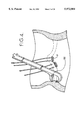
- FIG. 25 shows the tensioning tool just as it cuts the legs of the fastener.
- the handle section of tool 60 includes a gripping handle portion 200 and a trigger portion 202.
- the anvil mechanism rod 192 has a proximal end 204 and is connected to a trigger element 206 by a pin 208.
- a pivot pin 210 is mounted on handle portion 200 and trigger element 206 pivots in direction 211 when operated. Moving the trigger element 206 in direction 210 moves the anvil body 190 in direction F shown in FIG. 28 to form the fastener.
- the handle section also includes a cutter handle 212 that is also pivotally mounted on the handle 200 to be moved in direction 214 by the surgeon.
Abstract
Description
Claims (13)
Priority Applications (2)
| Application Number | Priority Date | Filing Date | Title |
|---|---|---|---|
| US09/026,671 US5972004A (en) | 1996-02-23 | 1998-02-20 | Wire fasteners for use in minimally invasive surgery and apparatus and methods for handling those fasteners |
| US09/369,196 US6162233A (en) | 1996-02-23 | 1999-08-06 | Wire fasteners for use in minimally invasive surgery and means and methods for handling those fasteners |
Applications Claiming Priority (3)
| Application Number | Priority Date | Filing Date | Title |
|---|---|---|---|
| US08/606,343 US5716370A (en) | 1996-02-23 | 1996-02-23 | Means for replacing a heart valve in a minimally invasive manner |
| US08/802,948 US6042607A (en) | 1996-02-23 | 1997-02-21 | Means and method of replacing a heart valve in a minimally invasive manner |
| US09/026,671 US5972004A (en) | 1996-02-23 | 1998-02-20 | Wire fasteners for use in minimally invasive surgery and apparatus and methods for handling those fasteners |
Related Parent Applications (1)
| Application Number | Title | Priority Date | Filing Date |
|---|---|---|---|
| US08/802,948 Continuation-In-Part US6042607A (en) | 1996-02-23 | 1997-02-21 | Means and method of replacing a heart valve in a minimally invasive manner |
Related Child Applications (1)
| Application Number | Title | Priority Date | Filing Date |
|---|---|---|---|
| US09/369,196 Division US6162233A (en) | 1996-02-23 | 1999-08-06 | Wire fasteners for use in minimally invasive surgery and means and methods for handling those fasteners |
Publications (1)
| Publication Number | Publication Date |
|---|---|
| US5972004A true US5972004A (en) | 1999-10-26 |
Family
ID=46253972
Family Applications (1)
| Application Number | Title | Priority Date | Filing Date |
|---|---|---|---|
| US09/026,671 Expired - Lifetime US5972004A (en) | 1996-02-23 | 1998-02-20 | Wire fasteners for use in minimally invasive surgery and apparatus and methods for handling those fasteners |
Country Status (1)
| Country | Link |
|---|---|
| US (1) | US5972004A (en) |
Cited By (126)
| Publication number | Priority date | Publication date | Assignee | Title |
|---|---|---|---|---|
| US6162233A (en) * | 1996-02-23 | 2000-12-19 | Cardiovascular Technologies, Llc | Wire fasteners for use in minimally invasive surgery and means and methods for handling those fasteners |
| WO2002015798A3 (en) * | 2000-08-25 | 2002-05-16 | Sulzer Carbomedics Inc | Method and apparatus for stapling an annuloplasty band in-situ |
| EP1330189A2 (en) * | 2000-06-23 | 2003-07-30 | Viacor Incorporated | Automated annular plication for mitral valve repair |
| WO2003105670A2 (en) | 2002-01-10 | 2003-12-24 | Guided Delivery Systems, Inc. | Devices and methods for heart valve repair |
| US20040050393A1 (en) * | 2002-09-12 | 2004-03-18 | Steve Golden | Anastomosis apparatus and methods |
| US20040093024A1 (en) * | 2000-09-01 | 2004-05-13 | James Lousararian | Advanced wound site management systems and methods |
| US20040167573A1 (en) * | 1996-02-23 | 2004-08-26 | Cardviovascular Technologies, L.L.C. | Extremely long wire fasteners for use in minimally invasive surgery and means and methods for handling those fasteners |
| US20040236419A1 (en) * | 2001-12-21 | 2004-11-25 | Simcha Milo | Implantation system for annuloplasty rings |
| US20050067457A1 (en) * | 2003-09-29 | 2005-03-31 | Shelton Frederick E. | Surgical stapling instrument with multistroke firing incorporating an anti-backup mechanism |
| US20050131429A1 (en) * | 2003-12-10 | 2005-06-16 | Liem Ho | Surgical connection apparatus and methods |
| US20070149845A1 (en) * | 2003-11-21 | 2007-06-28 | Kuhns Jesse J | Diagnostic device for tubular anatomical structures |
| US20070179604A1 (en) * | 2006-01-27 | 2007-08-02 | Ernest Lane | Gasket with spring collar for prosthetic heart valves and methods for making and using them |
| US20080208217A1 (en) * | 2007-02-26 | 2008-08-28 | Adams Mark L | Hemostatic clip and delivery system |
| US20090105751A1 (en) * | 2007-10-18 | 2009-04-23 | John Zentgraf | Minimally invasive repair of a valve leaflet in a beating heart |
| US7534204B2 (en) | 2003-09-03 | 2009-05-19 | Guided Delivery Systems, Inc. | Cardiac visualization devices and methods |
| US20090177277A1 (en) * | 2001-12-21 | 2009-07-09 | Simcha Milo | Implantation system for annuloplasty rings |
| US7588582B2 (en) | 2002-06-13 | 2009-09-15 | Guided Delivery Systems Inc. | Methods for remodeling cardiac tissue |
| US7666193B2 (en) | 2002-06-13 | 2010-02-23 | Guided Delivery Sytems, Inc. | Delivery devices and methods for heart valve repair |
| US7666194B2 (en) | 2000-10-20 | 2010-02-23 | Onux Medical, Inc. | Surgical suturing instrument and method of use |
| US7753924B2 (en) | 2003-09-04 | 2010-07-13 | Guided Delivery Systems, Inc. | Delivery devices and methods for heart valve repair |
| US7753922B2 (en) | 2003-09-04 | 2010-07-13 | Guided Delivery Systems, Inc. | Devices and methods for cardiac annulus stabilization and treatment |
| US7753858B2 (en) | 2002-06-13 | 2010-07-13 | Guided Delivery Systems, Inc. | Delivery devices and methods for heart valve repair |
| US7758637B2 (en) | 2003-02-06 | 2010-07-20 | Guided Delivery Systems, Inc. | Delivery devices and methods for heart valve repair |
| US7819915B2 (en) | 2000-07-27 | 2010-10-26 | Edwards Lifesciences Corporation | Heart valve holders and handling clips therefor |
| US7883538B2 (en) | 2002-06-13 | 2011-02-08 | Guided Delivery Systems Inc. | Methods and devices for termination |
| US7896892B2 (en) | 2000-03-31 | 2011-03-01 | Medtronic, Inc. | Multiple bias surgical fastener |
| US7914544B2 (en) | 2000-10-10 | 2011-03-29 | Medtronic, Inc. | Minimally invasive valve repair procedure and apparatus |
| US7951197B2 (en) | 2005-04-08 | 2011-05-31 | Medtronic, Inc. | Two-piece prosthetic valves with snap-in connection and methods for use |
| US7959674B2 (en) | 2002-07-16 | 2011-06-14 | Medtronic, Inc. | Suture locking assembly and method of use |
| US7972377B2 (en) | 2001-12-27 | 2011-07-05 | Medtronic, Inc. | Bioprosthetic heart valve |
| US7981153B2 (en) | 2002-12-20 | 2011-07-19 | Medtronic, Inc. | Biologically implantable prosthesis methods of using |
| US8021161B2 (en) | 2006-05-01 | 2011-09-20 | Edwards Lifesciences Corporation | Simulated heart valve root for training and testing |
| US8021421B2 (en) | 2003-08-22 | 2011-09-20 | Medtronic, Inc. | Prosthesis heart valve fixturing device |
| US8066766B2 (en) | 2002-06-13 | 2011-11-29 | Guided Delivery Systems Inc. | Methods and devices for termination |
| US8118822B2 (en) | 1999-03-01 | 2012-02-21 | Medtronic, Inc. | Bridge clip tissue connector apparatus and methods |
| US20120165930A1 (en) * | 2010-12-23 | 2012-06-28 | The Foundy, Llc | System for mitral valve repair and replacement |
| US8211169B2 (en) | 2005-05-27 | 2012-07-03 | Medtronic, Inc. | Gasket with collar for prosthetic heart valves and methods for using them |
| US8287555B2 (en) | 2003-02-06 | 2012-10-16 | Guided Delivery Systems, Inc. | Devices and methods for heart valve repair |
| US8308798B2 (en) | 2008-12-19 | 2012-11-13 | Edwards Lifesciences Corporation | Quick-connect prosthetic heart valve and methods |
| US8348998B2 (en) | 2009-06-26 | 2013-01-08 | Edwards Lifesciences Corporation | Unitary quick connect prosthetic heart valve and deployment system and methods |
| US8353921B2 (en) | 1999-03-01 | 2013-01-15 | Medtronic, Inc | Tissue connector apparatus and methods |
| US8449625B2 (en) | 2009-10-27 | 2013-05-28 | Edwards Lifesciences Corporation | Methods of measuring heart valve annuluses for valve replacement |
| US8506625B2 (en) | 2005-07-13 | 2013-08-13 | Edwards Lifesciences Corporation | Contoured sewing ring for a prosthetic mitral heart valve |
| US8574257B2 (en) | 2005-02-10 | 2013-11-05 | Edwards Lifesciences Corporation | System, device, and method for providing access in a cardiovascular environment |
| US8603161B2 (en) | 2003-10-08 | 2013-12-10 | Medtronic, Inc. | Attachment device and methods of using the same |
| US8641757B2 (en) | 2010-09-10 | 2014-02-04 | Edwards Lifesciences Corporation | Systems for rapidly deploying surgical heart valves |
| US8641727B2 (en) | 2002-06-13 | 2014-02-04 | Guided Delivery Systems, Inc. | Devices and methods for heart valve repair |
| US8790367B2 (en) | 2008-02-06 | 2014-07-29 | Guided Delivery Systems Inc. | Multi-window guide tunnel |
| US8795298B2 (en) | 2008-10-10 | 2014-08-05 | Guided Delivery Systems Inc. | Tether tensioning devices and related methods |
| US8821569B2 (en) | 2006-04-29 | 2014-09-02 | Medtronic, Inc. | Multiple component prosthetic heart valve assemblies and methods for delivering them |
| US8845720B2 (en) | 2010-09-27 | 2014-09-30 | Edwards Lifesciences Corporation | Prosthetic heart valve frame with flexible commissures |
| US8968338B2 (en) | 2005-01-21 | 2015-03-03 | Mayo Foundation For Medical Education And Research | Thorascopic heart valve repair method and apparatus |
| US8986374B2 (en) | 2010-05-10 | 2015-03-24 | Edwards Lifesciences Corporation | Prosthetic heart valve |
| US9044221B2 (en) | 2010-12-29 | 2015-06-02 | Neochord, Inc. | Exchangeable system for minimally invasive beating heart repair of heart valve leaflets |
| US9078747B2 (en) | 2011-12-21 | 2015-07-14 | Edwards Lifesciences Corporation | Anchoring device for replacing or repairing a heart valve |
| US9125741B2 (en) | 2010-09-10 | 2015-09-08 | Edwards Lifesciences Corporation | Systems and methods for ensuring safe and rapid deployment of prosthetic heart valves |
| US9155617B2 (en) | 2004-01-23 | 2015-10-13 | Edwards Lifesciences Corporation | Prosthetic mitral valve |
| US9248016B2 (en) | 2009-03-31 | 2016-02-02 | Edwards Lifesciences Corporation | Prosthetic heart valve system |
| US9314334B2 (en) | 2008-11-25 | 2016-04-19 | Edwards Lifesciences Corporation | Conformal expansion of prosthetic devices to anatomical shapes |
| US9370418B2 (en) | 2010-09-10 | 2016-06-21 | Edwards Lifesciences Corporation | Rapidly deployable surgical heart valves |
| US9439762B2 (en) | 2000-06-01 | 2016-09-13 | Edwards Lifesciences Corporation | Methods of implant of a heart valve with a convertible sewing ring |
| US9468527B2 (en) | 2013-06-12 | 2016-10-18 | Edwards Lifesciences Corporation | Cardiac implant with integrated suture fasteners |
| US9504566B2 (en) | 2014-06-20 | 2016-11-29 | Edwards Lifesciences Corporation | Surgical heart valves identifiable post-implant |
| US9549816B2 (en) | 2014-04-03 | 2017-01-24 | Edwards Lifesciences Corporation | Method for manufacturing high durability heart valve |
| US9554903B2 (en) | 2005-05-24 | 2017-01-31 | Edwards Lifesciences Corporation | Rapid deployment prosthetic heart valve |
| US9554901B2 (en) | 2010-05-12 | 2017-01-31 | Edwards Lifesciences Corporation | Low gradient prosthetic heart valve |
| US9572662B2 (en) | 2011-06-21 | 2017-02-21 | Twelve, Inc. | Prosthetic heart valve devices and associated systems and methods |
| US9579198B2 (en) | 2012-03-01 | 2017-02-28 | Twelve, Inc. | Hydraulic delivery systems for prosthetic heart valve devices and associated methods |
| US9585752B2 (en) | 2014-04-30 | 2017-03-07 | Edwards Lifesciences Corporation | Holder and deployment system for surgical heart valves |
| US9616197B2 (en) | 2009-01-20 | 2017-04-11 | Ancora Heart, Inc. | Anchor deployment devices and related methods |
| US9636106B2 (en) | 2008-10-10 | 2017-05-02 | Ancora Heart, Inc. | Termination devices and related methods |
| US9655722B2 (en) | 2011-10-19 | 2017-05-23 | Twelve, Inc. | Prosthetic heart valve devices, prosthetic mitral valves and associated systems and methods |
| US9763780B2 (en) | 2011-10-19 | 2017-09-19 | Twelve, Inc. | Devices, systems and methods for heart valve replacement |
| US9861350B2 (en) | 2010-09-03 | 2018-01-09 | Ancora Heart, Inc. | Devices and methods for anchoring tissue |
| US9901443B2 (en) | 2011-10-19 | 2018-02-27 | Twelve, Inc. | Prosthetic heart valve devices, prosthetic mitral valves and associated systems and methods |
| US9919137B2 (en) | 2013-08-28 | 2018-03-20 | Edwards Lifesciences Corporation | Integrated balloon catheter inflation system |
| US9949829B2 (en) | 2002-06-13 | 2018-04-24 | Ancora Heart, Inc. | Delivery devices and methods for heart valve repair |
| US10052204B2 (en) | 2011-10-19 | 2018-08-21 | Twelve, Inc. | Prosthetic heart valve devices, prosthetic mitral valves and associated systems and methods |
| US10058321B2 (en) | 2015-03-05 | 2018-08-28 | Ancora Heart, Inc. | Devices and methods of visualizing and determining depth of penetration in cardiac tissue |
| US10058425B2 (en) | 2013-03-15 | 2018-08-28 | Edwards Lifesciences Corporation | Methods of assembling a valved aortic conduit |
| US10080653B2 (en) | 2015-09-10 | 2018-09-25 | Edwards Lifesciences Corporation | Limited expansion heart valve |
| US10111747B2 (en) | 2013-05-20 | 2018-10-30 | Twelve, Inc. | Implantable heart valve devices, mitral valve repair devices and associated systems and methods |
| EP3417832A1 (en) * | 2017-06-22 | 2018-12-26 | Medtentia International Ltd Oy | Medical securing device for securing an object with a securing member |
| US10238490B2 (en) | 2015-08-21 | 2019-03-26 | Twelve, Inc. | Implant heart valve devices, mitral valve repair devices and associated systems and methods |
| USD846122S1 (en) | 2016-12-16 | 2019-04-16 | Edwards Lifesciences Corporation | Heart valve sizer |
| US10265172B2 (en) | 2016-04-29 | 2019-04-23 | Medtronic Vascular, Inc. | Prosthetic heart valve devices with tethered anchors and associated systems and methods |
| US10433961B2 (en) | 2017-04-18 | 2019-10-08 | Twelve, Inc. | Delivery systems with tethers for prosthetic heart valve devices and associated methods |
| US10441415B2 (en) | 2013-09-20 | 2019-10-15 | Edwards Lifesciences Corporation | Heart valves with increased effective orifice area |
| US10456245B2 (en) | 2016-05-16 | 2019-10-29 | Edwards Lifesciences Corporation | System and method for applying material to a stent |
| US10456246B2 (en) | 2015-07-02 | 2019-10-29 | Edwards Lifesciences Corporation | Integrated hybrid heart valves |
| US10463485B2 (en) | 2017-04-06 | 2019-11-05 | Edwards Lifesciences Corporation | Prosthetic valve holders with automatic deploying mechanisms |
| USD867594S1 (en) | 2015-06-19 | 2019-11-19 | Edwards Lifesciences Corporation | Prosthetic heart valve |
| US10543080B2 (en) | 2011-05-20 | 2020-01-28 | Edwards Lifesciences Corporation | Methods of making encapsulated heart valves |
| US10575950B2 (en) | 2017-04-18 | 2020-03-03 | Twelve, Inc. | Hydraulic systems for delivering prosthetic heart valve devices and associated methods |
| US10588620B2 (en) | 2018-03-23 | 2020-03-17 | Neochord, Inc. | Device for suture attachment for minimally invasive heart valve repair |
| US10646338B2 (en) | 2017-06-02 | 2020-05-12 | Twelve, Inc. | Delivery systems with telescoping capsules for deploying prosthetic heart valve devices and associated methods |
| US10667904B2 (en) | 2016-03-08 | 2020-06-02 | Edwards Lifesciences Corporation | Valve implant with integrated sensor and transmitter |
| US10667914B2 (en) | 2016-11-18 | 2020-06-02 | Ancora Heart, Inc. | Myocardial implant load sharing device and methods to promote LV function |
| US10695170B2 (en) | 2015-07-02 | 2020-06-30 | Edwards Lifesciences Corporation | Hybrid heart valves adapted for post-implant expansion |
| US10695178B2 (en) | 2011-06-01 | 2020-06-30 | Neochord, Inc. | Minimally invasive repair of heart valve leaflets |
| US10702380B2 (en) | 2011-10-19 | 2020-07-07 | Twelve, Inc. | Devices, systems and methods for heart valve replacement |
| US10702378B2 (en) | 2017-04-18 | 2020-07-07 | Twelve, Inc. | Prosthetic heart valve device and associated systems and methods |
| US10709591B2 (en) | 2017-06-06 | 2020-07-14 | Twelve, Inc. | Crimping device and method for loading stents and prosthetic heart valves |
| US10722316B2 (en) | 2013-11-06 | 2020-07-28 | Edwards Lifesciences Corporation | Bioprosthetic heart valves having adaptive seals to minimize paravalvular leakage |
| US10729541B2 (en) | 2017-07-06 | 2020-08-04 | Twelve, Inc. | Prosthetic heart valve devices and associated systems and methods |
| US10765517B2 (en) | 2015-10-01 | 2020-09-08 | Neochord, Inc. | Ringless web for repair of heart valves |
| US10786352B2 (en) | 2017-07-06 | 2020-09-29 | Twelve, Inc. | Prosthetic heart valve devices and associated systems and methods |
| US10792151B2 (en) | 2017-05-11 | 2020-10-06 | Twelve, Inc. | Delivery systems for delivering prosthetic heart valve devices and associated methods |
| US10799353B2 (en) | 2017-04-28 | 2020-10-13 | Edwards Lifesciences Corporation | Prosthetic heart valve with collapsible holder |
| USD908874S1 (en) | 2018-07-11 | 2021-01-26 | Edwards Lifesciences Corporation | Collapsible heart valve sizer |
| JP2021509614A (en) * | 2018-01-03 | 2021-04-01 | カーディアック・インプランツ・エルエルシー | Fasteners to hold the tightening cord in a reduced diameter around the heart valve annulus, and attachment of fasteners |
| US10966709B2 (en) | 2018-09-07 | 2021-04-06 | Neochord, Inc. | Device for suture attachment for minimally invasive heart valve repair |
| US10980973B2 (en) | 2015-05-12 | 2021-04-20 | Ancora Heart, Inc. | Device and method for releasing catheters from cardiac structures |
| US11007058B2 (en) | 2013-03-15 | 2021-05-18 | Edwards Lifesciences Corporation | Valved aortic conduits |
| US11116496B2 (en) | 2014-04-08 | 2021-09-14 | Lsi Solutions, Inc. | Surgical suturing device for a replacement anatomical structure and methods thereof |
| US11135057B2 (en) | 2017-06-21 | 2021-10-05 | Edwards Lifesciences Corporation | Dual-wireform limited expansion heart valves |
| US11173030B2 (en) | 2018-05-09 | 2021-11-16 | Neochord, Inc. | Suture length adjustment for minimally invasive heart valve repair |
| US11202704B2 (en) | 2011-10-19 | 2021-12-21 | Twelve, Inc. | Prosthetic heart valve devices, prosthetic mitral valves and associated systems and methods |
| US11253360B2 (en) | 2018-05-09 | 2022-02-22 | Neochord, Inc. | Low profile tissue anchor for minimally invasive heart valve repair |
| US11337805B2 (en) | 2018-01-23 | 2022-05-24 | Edwards Lifesciences Corporation | Prosthetic valve holders, systems, and methods |
| US11376126B2 (en) | 2019-04-16 | 2022-07-05 | Neochord, Inc. | Transverse helical cardiac anchor for minimally invasive heart valve repair |
| US11554012B2 (en) | 2019-12-16 | 2023-01-17 | Edwards Lifesciences Corporation | Valve holder assembly with suture looping protection |
| US11589989B2 (en) | 2017-03-31 | 2023-02-28 | Neochord, Inc. | Minimally invasive heart valve repair in a beating heart |
| US11672524B2 (en) | 2019-07-15 | 2023-06-13 | Ancora Heart, Inc. | Devices and methods for tether cutting |
| US11690709B2 (en) | 2015-09-02 | 2023-07-04 | Edwards Lifesciences Corporation | Methods for securing a transcatheter valve to a bioprosthetic cardiac structure |
| US11951006B2 (en) | 2023-01-04 | 2024-04-09 | Edwards Lifesciences Corporation | Valve holder assembly with suture looping protection |
Citations (2)
| Publication number | Priority date | Publication date | Assignee | Title |
|---|---|---|---|---|
| US5171250A (en) * | 1987-05-14 | 1992-12-15 | Inbae Yoon | Surgical clips and surgical clip applicator and cutting and transection device |
| US5665096A (en) * | 1995-03-07 | 1997-09-09 | Yoon; Inbae | Needle driving apparatus and methods of suturing tissue |
-
1998
- 1998-02-20 US US09/026,671 patent/US5972004A/en not_active Expired - Lifetime
Patent Citations (2)
| Publication number | Priority date | Publication date | Assignee | Title |
|---|---|---|---|---|
| US5171250A (en) * | 1987-05-14 | 1992-12-15 | Inbae Yoon | Surgical clips and surgical clip applicator and cutting and transection device |
| US5665096A (en) * | 1995-03-07 | 1997-09-09 | Yoon; Inbae | Needle driving apparatus and methods of suturing tissue |
Cited By (274)
| Publication number | Priority date | Publication date | Assignee | Title |
|---|---|---|---|---|
| US6162233A (en) * | 1996-02-23 | 2000-12-19 | Cardiovascular Technologies, Llc | Wire fasteners for use in minimally invasive surgery and means and methods for handling those fasteners |
| US20040167573A1 (en) * | 1996-02-23 | 2004-08-26 | Cardviovascular Technologies, L.L.C. | Extremely long wire fasteners for use in minimally invasive surgery and means and methods for handling those fasteners |
| US7722642B2 (en) * | 1996-02-23 | 2010-05-25 | Medtronic, Inc. | Extremely long wire fasteners for use in minimally invasive surgery and means and methods for handling those fasteners |
| US8118822B2 (en) | 1999-03-01 | 2012-02-21 | Medtronic, Inc. | Bridge clip tissue connector apparatus and methods |
| US8353921B2 (en) | 1999-03-01 | 2013-01-15 | Medtronic, Inc | Tissue connector apparatus and methods |
| US7896892B2 (en) | 2000-03-31 | 2011-03-01 | Medtronic, Inc. | Multiple bias surgical fastener |
| US8353092B2 (en) | 2000-03-31 | 2013-01-15 | Medtronic, Inc. | Multiple bias surgical fastener |
| US10238486B2 (en) | 2000-06-01 | 2019-03-26 | Edwards Lifesciences Corporation | Heart valve with integrated stent and sewing ring |
| US9439762B2 (en) | 2000-06-01 | 2016-09-13 | Edwards Lifesciences Corporation | Methods of implant of a heart valve with a convertible sewing ring |
| EP1330189A2 (en) * | 2000-06-23 | 2003-07-30 | Viacor Incorporated | Automated annular plication for mitral valve repair |
| EP1330189A4 (en) * | 2000-06-23 | 2004-09-08 | Viacor Inc | Automated annular plication for mitral valve repair |
| US20040243153A1 (en) * | 2000-06-23 | 2004-12-02 | Liddicoat John R. | Automated annular plication for mitral valve repair |
| US7819915B2 (en) | 2000-07-27 | 2010-10-26 | Edwards Lifesciences Corporation | Heart valve holders and handling clips therefor |
| WO2002015798A3 (en) * | 2000-08-25 | 2002-05-16 | Sulzer Carbomedics Inc | Method and apparatus for stapling an annuloplasty band in-situ |
| US6524338B1 (en) | 2000-08-25 | 2003-02-25 | Steven R. Gundry | Method and apparatus for stapling an annuloplasty band in-situ |
| US20040093024A1 (en) * | 2000-09-01 | 2004-05-13 | James Lousararian | Advanced wound site management systems and methods |
| US7914544B2 (en) | 2000-10-10 | 2011-03-29 | Medtronic, Inc. | Minimally invasive valve repair procedure and apparatus |
| US7666194B2 (en) | 2000-10-20 | 2010-02-23 | Onux Medical, Inc. | Surgical suturing instrument and method of use |
| US8123801B2 (en) | 2001-12-21 | 2012-02-28 | QuickRing Medical Technologies, Ltd. | Implantation system for annuloplasty rings |
| US7485142B2 (en) | 2001-12-21 | 2009-02-03 | Simcha Milo | Implantation system for annuloplasty rings |
| US20090177277A1 (en) * | 2001-12-21 | 2009-07-09 | Simcha Milo | Implantation system for annuloplasty rings |
| US20040236419A1 (en) * | 2001-12-21 | 2004-11-25 | Simcha Milo | Implantation system for annuloplasty rings |
| US7972377B2 (en) | 2001-12-27 | 2011-07-05 | Medtronic, Inc. | Bioprosthetic heart valve |
| WO2003105670A2 (en) | 2002-01-10 | 2003-12-24 | Guided Delivery Systems, Inc. | Devices and methods for heart valve repair |
| US10624741B2 (en) | 2002-06-13 | 2020-04-21 | Ancora Heart, Inc. | Delivery devices and methods for heart valve repair |
| US9072513B2 (en) | 2002-06-13 | 2015-07-07 | Guided Delivery Systems Inc. | Methods and devices for termination |
| US7588582B2 (en) | 2002-06-13 | 2009-09-15 | Guided Delivery Systems Inc. | Methods for remodeling cardiac tissue |
| US8641727B2 (en) | 2002-06-13 | 2014-02-04 | Guided Delivery Systems, Inc. | Devices and methods for heart valve repair |
| US7753858B2 (en) | 2002-06-13 | 2010-07-13 | Guided Delivery Systems, Inc. | Delivery devices and methods for heart valve repair |
| US10092402B2 (en) | 2002-06-13 | 2018-10-09 | Ancora Heart, Inc. | Devices and methods for heart valve repair |
| US8066766B2 (en) | 2002-06-13 | 2011-11-29 | Guided Delivery Systems Inc. | Methods and devices for termination |
| US9226825B2 (en) | 2002-06-13 | 2016-01-05 | Guided Delivery Systems, Inc. | Delivery devices and methods for heart valve repair |
| US7883538B2 (en) | 2002-06-13 | 2011-02-08 | Guided Delivery Systems Inc. | Methods and devices for termination |
| US7666193B2 (en) | 2002-06-13 | 2010-02-23 | Guided Delivery Sytems, Inc. | Delivery devices and methods for heart valve repair |
| US9468528B2 (en) | 2002-06-13 | 2016-10-18 | Guided Delivery Systems, Inc. | Devices and methods for heart valve repair |
| US9949829B2 (en) | 2002-06-13 | 2018-04-24 | Ancora Heart, Inc. | Delivery devices and methods for heart valve repair |
| US6986775B2 (en) | 2002-06-13 | 2006-01-17 | Guided Delivery Systems, Inc. | Devices and methods for heart valve repair |
| US9636107B2 (en) | 2002-06-13 | 2017-05-02 | Ancora Heart, Inc. | Devices and methods for heart valve repair |
| US8287557B2 (en) | 2002-06-13 | 2012-10-16 | Guided Delivery Systems, Inc. | Methods and devices for termination |
| US10898328B2 (en) | 2002-06-13 | 2021-01-26 | Ancora Heart, Inc. | Devices and methods for heart valve repair |
| US7959674B2 (en) | 2002-07-16 | 2011-06-14 | Medtronic, Inc. | Suture locking assembly and method of use |
| US8349003B2 (en) | 2002-07-16 | 2013-01-08 | Medtronic, Inc. | Suture locking assembly and method of use |
| US8066724B2 (en) | 2002-09-12 | 2011-11-29 | Medtronic, Inc. | Anastomosis apparatus and methods |
| US20040050393A1 (en) * | 2002-09-12 | 2004-03-18 | Steve Golden | Anastomosis apparatus and methods |
| US8551162B2 (en) | 2002-12-20 | 2013-10-08 | Medtronic, Inc. | Biologically implantable prosthesis |
| US9333078B2 (en) | 2002-12-20 | 2016-05-10 | Medtronic, Inc. | Heart valve assemblies |
| US7981153B2 (en) | 2002-12-20 | 2011-07-19 | Medtronic, Inc. | Biologically implantable prosthesis methods of using |
| US8623080B2 (en) | 2002-12-20 | 2014-01-07 | Medtronic, Inc. | Biologically implantable prosthesis and methods of using the same |
| US10595991B2 (en) | 2002-12-20 | 2020-03-24 | Medtronic, Inc. | Heart valve assemblies |
| US8460373B2 (en) | 2002-12-20 | 2013-06-11 | Medtronic, Inc. | Method for implanting a heart valve within an annulus of a patient |
| US8025695B2 (en) | 2002-12-20 | 2011-09-27 | Medtronic, Inc. | Biologically implantable heart valve system |
| US7758637B2 (en) | 2003-02-06 | 2010-07-20 | Guided Delivery Systems, Inc. | Delivery devices and methods for heart valve repair |
| US8287555B2 (en) | 2003-02-06 | 2012-10-16 | Guided Delivery Systems, Inc. | Devices and methods for heart valve repair |
| US8021421B2 (en) | 2003-08-22 | 2011-09-20 | Medtronic, Inc. | Prosthesis heart valve fixturing device |
| US8747463B2 (en) | 2003-08-22 | 2014-06-10 | Medtronic, Inc. | Methods of using a prosthesis fixturing device |
| US7534204B2 (en) | 2003-09-03 | 2009-05-19 | Guided Delivery Systems, Inc. | Cardiac visualization devices and methods |
| US8343173B2 (en) | 2003-09-04 | 2013-01-01 | Guided Delivery Systems Inc. | Delivery devices and methods for heart valve repair |
| US7922762B2 (en) | 2003-09-04 | 2011-04-12 | Guided Delivery Systems Inc. | Devices and methods for cardiac annulus stabilization and treatment |
| EP2374415A1 (en) | 2003-09-04 | 2011-10-12 | Guided Delivery Systems, Inc. | Delivery devices for heart valve repair |
| EP2377469A1 (en) | 2003-09-04 | 2011-10-19 | Guided Delivery Systems, Inc. | Delivery devices for heart valve repair |
| US7753924B2 (en) | 2003-09-04 | 2010-07-13 | Guided Delivery Systems, Inc. | Delivery devices and methods for heart valve repair |
| US7753922B2 (en) | 2003-09-04 | 2010-07-13 | Guided Delivery Systems, Inc. | Devices and methods for cardiac annulus stabilization and treatment |
| EP3424436A1 (en) | 2003-09-04 | 2019-01-09 | Ancora Heart, Inc. | Delivery devices for heart valve repair |
| US20050067457A1 (en) * | 2003-09-29 | 2005-03-31 | Shelton Frederick E. | Surgical stapling instrument with multistroke firing incorporating an anti-backup mechanism |
| US6959852B2 (en) * | 2003-09-29 | 2005-11-01 | Ethicon Endo-Surgery, Inc. | Surgical stapling instrument with multistroke firing incorporating an anti-backup mechanism |
| US8603161B2 (en) | 2003-10-08 | 2013-12-10 | Medtronic, Inc. | Attachment device and methods of using the same |
| US20070149845A1 (en) * | 2003-11-21 | 2007-06-28 | Kuhns Jesse J | Diagnostic device for tubular anatomical structures |
| US9173546B2 (en) * | 2003-11-21 | 2015-11-03 | Antonio Longo | Diagnostic device for tubular anatomical structures |
| US7879047B2 (en) | 2003-12-10 | 2011-02-01 | Medtronic, Inc. | Surgical connection apparatus and methods |
| US20050131429A1 (en) * | 2003-12-10 | 2005-06-16 | Liem Ho | Surgical connection apparatus and methods |
| US10342661B2 (en) | 2004-01-23 | 2019-07-09 | Edwards Lifesciences Corporation | Prosthetic mitral valve |
| US10085836B2 (en) | 2004-01-23 | 2018-10-02 | Edwards Lifesciences Corporation | Prosthetic mitral valve |
| US9155617B2 (en) | 2004-01-23 | 2015-10-13 | Edwards Lifesciences Corporation | Prosthetic mitral valve |
| US9730794B2 (en) | 2004-01-23 | 2017-08-15 | Edwards Lifesciences Corporation | Prosthetic mitral valve |
| US11534156B2 (en) | 2005-01-21 | 2022-12-27 | Mayo Foundation For Medical Education And Research | Thorascopic heart valve repair method and apparatus |
| US9364213B2 (en) | 2005-01-21 | 2016-06-14 | Mayo Foundation For Medical Education And Research | Thorascopic heart valve repair method |
| US8968338B2 (en) | 2005-01-21 | 2015-03-03 | Mayo Foundation For Medical Education And Research | Thorascopic heart valve repair method and apparatus |
| US9700300B2 (en) | 2005-01-21 | 2017-07-11 | Mayo Foundation For Medical Education And Research | Thorascopic heart valve repair apparatus |
| US10582924B2 (en) | 2005-01-21 | 2020-03-10 | Mayo Foundation For Medical Education And Research | Thorascopic heart valve repair method |
| US8574257B2 (en) | 2005-02-10 | 2013-11-05 | Edwards Lifesciences Corporation | System, device, and method for providing access in a cardiovascular environment |
| US7951197B2 (en) | 2005-04-08 | 2011-05-31 | Medtronic, Inc. | Two-piece prosthetic valves with snap-in connection and methods for use |
| US8500802B2 (en) | 2005-04-08 | 2013-08-06 | Medtronic, Inc. | Two-piece prosthetic valves with snap-in connection and methods for use |
| US9554903B2 (en) | 2005-05-24 | 2017-01-31 | Edwards Lifesciences Corporation | Rapid deployment prosthetic heart valve |
| US10130468B2 (en) | 2005-05-24 | 2018-11-20 | Edwards Lifesciences Corporation | Replacement prosthetic heart valves |
| US11284998B2 (en) | 2005-05-24 | 2022-03-29 | Edwards Lifesciences Corporation | Surgical methods of replacing prosthetic heart valves |
| US10456251B2 (en) | 2005-05-24 | 2019-10-29 | Edwards Lifesciences Corporation | Surgical methods of replacing prosthetic heart valves |
| US8211169B2 (en) | 2005-05-27 | 2012-07-03 | Medtronic, Inc. | Gasket with collar for prosthetic heart valves and methods for using them |
| US8506625B2 (en) | 2005-07-13 | 2013-08-13 | Edwards Lifesciences Corporation | Contoured sewing ring for a prosthetic mitral heart valve |
| US20070179604A1 (en) * | 2006-01-27 | 2007-08-02 | Ernest Lane | Gasket with spring collar for prosthetic heart valves and methods for making and using them |
| US7967857B2 (en) | 2006-01-27 | 2011-06-28 | Medtronic, Inc. | Gasket with spring collar for prosthetic heart valves and methods for making and using them |
| US8821569B2 (en) | 2006-04-29 | 2014-09-02 | Medtronic, Inc. | Multiple component prosthetic heart valve assemblies and methods for delivering them |
| US8021161B2 (en) | 2006-05-01 | 2011-09-20 | Edwards Lifesciences Corporation | Simulated heart valve root for training and testing |
| US8845658B2 (en) | 2007-02-26 | 2014-09-30 | Boston Scientific Scimed, Inc. | Hemostatic clip and delivery system |
| US20080208217A1 (en) * | 2007-02-26 | 2008-08-28 | Adams Mark L | Hemostatic clip and delivery system |
| US8758393B2 (en) * | 2007-10-18 | 2014-06-24 | Neochord, Inc. | Minimally invasive repair of a valve leaflet in a beating heart |
| US11419602B2 (en) | 2007-10-18 | 2022-08-23 | Neochord, Inc. | Minimally invasive repair of a valve leaflet in a beating heart |
| US10507018B2 (en) | 2007-10-18 | 2019-12-17 | Neochord, Inc. | Minimally invasive repair of a valve leaflet in a beating heart |
| US9192374B2 (en) | 2007-10-18 | 2015-11-24 | Neochord, Inc. | Minimally invasive repair of a valve leaflet in a beating heart |
| US20090105751A1 (en) * | 2007-10-18 | 2009-04-23 | John Zentgraf | Minimally invasive repair of a valve leaflet in a beating heart |
| US8790367B2 (en) | 2008-02-06 | 2014-07-29 | Guided Delivery Systems Inc. | Multi-window guide tunnel |
| US10542987B2 (en) | 2008-02-06 | 2020-01-28 | Ancora Heart, Inc. | Multi-window guide tunnel |
| US9706996B2 (en) | 2008-02-06 | 2017-07-18 | Ancora Heart, Inc. | Multi-window guide tunnel |
| US9636106B2 (en) | 2008-10-10 | 2017-05-02 | Ancora Heart, Inc. | Termination devices and related methods |
| US8795298B2 (en) | 2008-10-10 | 2014-08-05 | Guided Delivery Systems Inc. | Tether tensioning devices and related methods |
| US10667906B2 (en) | 2008-11-25 | 2020-06-02 | Edwards Lifesciences Corporation | Methods of conformal expansion of prosthetic heart valves |
| US9314334B2 (en) | 2008-11-25 | 2016-04-19 | Edwards Lifesciences Corporation | Conformal expansion of prosthetic devices to anatomical shapes |
| US10182909B2 (en) | 2008-12-19 | 2019-01-22 | Edwards Lifesciences Corporation | Methods for quickly implanting a prosthetic heart valve |
| US8308798B2 (en) | 2008-12-19 | 2012-11-13 | Edwards Lifesciences Corporation | Quick-connect prosthetic heart valve and methods |
| US11504232B2 (en) | 2008-12-19 | 2022-11-22 | Edwards Lifesciences Corporation | Rapid implant prosthetic heart valve system |
| US9561100B2 (en) | 2008-12-19 | 2017-02-07 | Edwards Lifesciences Corporation | Systems for quickly delivering a prosthetic heart valve |
| US9005278B2 (en) | 2008-12-19 | 2015-04-14 | Edwards Lifesciences Corporation | Quick-connect prosthetic heart valve |
| US10799346B2 (en) | 2008-12-19 | 2020-10-13 | Edwards Lifesciences Corporation | Methods for quickly implanting a prosthetic heart valve |
| US9616197B2 (en) | 2009-01-20 | 2017-04-11 | Ancora Heart, Inc. | Anchor deployment devices and related methods |
| US10625047B2 (en) | 2009-01-20 | 2020-04-21 | Ancora Heart, Inc. | Anchor deployment devices and related methods |
| US9980818B2 (en) | 2009-03-31 | 2018-05-29 | Edwards Lifesciences Corporation | Prosthetic heart valve system with positioning markers |
| US9248016B2 (en) | 2009-03-31 | 2016-02-02 | Edwards Lifesciences Corporation | Prosthetic heart valve system |
| US9931207B2 (en) | 2009-03-31 | 2018-04-03 | Edwards Lifesciences Corporation | Methods of implanting a heart valve at an aortic annulus |
| US10842623B2 (en) | 2009-03-31 | 2020-11-24 | Edwards Lifesciences Corporation | Methods of implanting prosthetic heart valve using position markers |
| US9005277B2 (en) | 2009-06-26 | 2015-04-14 | Edwards Lifesciences Corporation | Unitary quick-connect prosthetic heart valve deployment system |
| US10555810B2 (en) | 2009-06-26 | 2020-02-11 | Edwards Lifesciences Corporation | Prosthetic heart valve deployment systems |
| US8696742B2 (en) | 2009-06-26 | 2014-04-15 | Edwards Lifesciences Corporation | Unitary quick-connect prosthetic heart valve deployment methods |
| US8348998B2 (en) | 2009-06-26 | 2013-01-08 | Edwards Lifesciences Corporation | Unitary quick connect prosthetic heart valve and deployment system and methods |
| US9603553B2 (en) | 2009-10-27 | 2017-03-28 | Edwards Lifesciences Corporation | Methods of measuring heart valve annuluses for valve replacement |
| US10231646B2 (en) | 2009-10-27 | 2019-03-19 | Edwards Lifesciences Corporation | Device for measuring an aortic valve annulus in an expanded condition |
| US11412954B2 (en) | 2009-10-27 | 2022-08-16 | Edwards Lifesciences Corporation | Device for measuring an aortic valve annulus in an expanded condition |
| US8449625B2 (en) | 2009-10-27 | 2013-05-28 | Edwards Lifesciences Corporation | Methods of measuring heart valve annuluses for valve replacement |
| US8986374B2 (en) | 2010-05-10 | 2015-03-24 | Edwards Lifesciences Corporation | Prosthetic heart valve |
| US11571299B2 (en) | 2010-05-10 | 2023-02-07 | Edwards Lifesciences Corporation | Methods for manufacturing resilient prosthetic surgical heart valves |
| US10702383B2 (en) | 2010-05-10 | 2020-07-07 | Edwards Lifesciences Corporation | Methods of delivering and implanting resilient prosthetic surgical heart valves |
| US9554901B2 (en) | 2010-05-12 | 2017-01-31 | Edwards Lifesciences Corporation | Low gradient prosthetic heart valve |
| US11266497B2 (en) | 2010-05-12 | 2022-03-08 | Edwards Lifesciences Corporation | Low gradient prosthetic heart valves |
| US10463480B2 (en) | 2010-05-12 | 2019-11-05 | Edwards Lifesciences Corporation | Leaflet for low gradient prosthetic heart valve |
| US9861350B2 (en) | 2010-09-03 | 2018-01-09 | Ancora Heart, Inc. | Devices and methods for anchoring tissue |
| US11775613B2 (en) | 2010-09-10 | 2023-10-03 | Edwards Lifesciences Corporation | Methods of safely expanding prosthetic heart valves |
| US9504563B2 (en) | 2010-09-10 | 2016-11-29 | Edwards Lifesciences Corporation | Rapidly deployable surgical heart valves |
| US11197757B2 (en) | 2010-09-10 | 2021-12-14 | Edwards Lifesciences Corporation | Methods of safely expanding prosthetic heart valves |
| US10039641B2 (en) | 2010-09-10 | 2018-08-07 | Edwards Lifesciences Corporation | Methods of rapidly deployable surgical heart valves |
| US8641757B2 (en) | 2010-09-10 | 2014-02-04 | Edwards Lifesciences Corporation | Systems for rapidly deploying surgical heart valves |
| US9370418B2 (en) | 2010-09-10 | 2016-06-21 | Edwards Lifesciences Corporation | Rapidly deployable surgical heart valves |
| US10722358B2 (en) | 2010-09-10 | 2020-07-28 | Edwards Lifesciences Corporation | Systems for rapidly deployable surgical heart valves |
| US9125741B2 (en) | 2010-09-10 | 2015-09-08 | Edwards Lifesciences Corporation | Systems and methods for ensuring safe and rapid deployment of prosthetic heart valves |
| US9968450B2 (en) | 2010-09-10 | 2018-05-15 | Edwards Lifesciences Corporation | Methods for ensuring safe and rapid deployment of prosthetic heart valves |
| US11471279B2 (en) | 2010-09-10 | 2022-10-18 | Edwards Lifesciences Corporation | Systems for rapidly deployable surgical heart valves |
| US10548728B2 (en) | 2010-09-10 | 2020-02-04 | Edwards Lifesciences Corporation | Safety systems for expansion of prosthetic heart valves |
| US8845720B2 (en) | 2010-09-27 | 2014-09-30 | Edwards Lifesciences Corporation | Prosthetic heart valve frame with flexible commissures |
| US11207178B2 (en) | 2010-09-27 | 2021-12-28 | Edwards Lifesciences Corporation | Collapsible-expandable heart valves |
| US10736741B2 (en) | 2010-09-27 | 2020-08-11 | Edwards Lifesciences Corporation | Methods of delivery of heart valves |
| US9861479B2 (en) | 2010-09-27 | 2018-01-09 | Edwards Lifesciences Corporation | Methods of delivery of flexible heart valves |
| US20120165930A1 (en) * | 2010-12-23 | 2012-06-28 | The Foundy, Llc | System for mitral valve repair and replacement |
| US10517725B2 (en) | 2010-12-23 | 2019-12-31 | Twelve, Inc. | System for mitral valve repair and replacement |
| US11571303B2 (en) | 2010-12-23 | 2023-02-07 | Twelve, Inc. | System for mitral valve repair and replacement |
| US9421098B2 (en) * | 2010-12-23 | 2016-08-23 | Twelve, Inc. | System for mitral valve repair and replacement |
| CN103491900A (en) * | 2010-12-23 | 2014-01-01 | 第七铸造纽克公司 | System for mitral valve repair and replacement |
| US10080659B1 (en) | 2010-12-29 | 2018-09-25 | Neochord, Inc. | Devices and methods for minimally invasive repair of heart valves |
| US9044221B2 (en) | 2010-12-29 | 2015-06-02 | Neochord, Inc. | Exchangeable system for minimally invasive beating heart repair of heart valve leaflets |
| US10130474B2 (en) | 2010-12-29 | 2018-11-20 | Neochord, Inc. | Exchangeable system for minimally invasive beating heart repair of heart valve leaflets |
| US10543080B2 (en) | 2011-05-20 | 2020-01-28 | Edwards Lifesciences Corporation | Methods of making encapsulated heart valves |
| US11517426B2 (en) | 2011-05-20 | 2022-12-06 | Edwards Lifesciences Corporation | Encapsulated heart valves |
| US10695178B2 (en) | 2011-06-01 | 2020-06-30 | Neochord, Inc. | Minimally invasive repair of heart valve leaflets |
| US9579196B2 (en) | 2011-06-21 | 2017-02-28 | Twelve, Inc. | Prosthetic heart valve devices and associated systems and methods |
| US9572662B2 (en) | 2011-06-21 | 2017-02-21 | Twelve, Inc. | Prosthetic heart valve devices and associated systems and methods |
| US9585751B2 (en) | 2011-06-21 | 2017-03-07 | Twelve, Inc. | Prosthetic heart valve devices and associated systems and methods |
| US10751173B2 (en) | 2011-06-21 | 2020-08-25 | Twelve, Inc. | Prosthetic heart valve devices and associated systems and methods |
| US10028827B2 (en) | 2011-06-21 | 2018-07-24 | Twelve, Inc. | Prosthetic heart valve devices and associated systems and methods |
| US10034750B2 (en) | 2011-06-21 | 2018-07-31 | Twelve, Inc. | Prosthetic heart valve devices and associated systems and methods |
| US11523900B2 (en) | 2011-06-21 | 2022-12-13 | Twelve, Inc. | Prosthetic heart valve devices and associated systems and methods |
| US11712334B2 (en) | 2011-06-21 | 2023-08-01 | Twelve, Inc. | Prosthetic heart valve devices and associated systems and methods |
| US10702380B2 (en) | 2011-10-19 | 2020-07-07 | Twelve, Inc. | Devices, systems and methods for heart valve replacement |
| US9655722B2 (en) | 2011-10-19 | 2017-05-23 | Twelve, Inc. | Prosthetic heart valve devices, prosthetic mitral valves and associated systems and methods |
| US9901443B2 (en) | 2011-10-19 | 2018-02-27 | Twelve, Inc. | Prosthetic heart valve devices, prosthetic mitral valves and associated systems and methods |
| US9763780B2 (en) | 2011-10-19 | 2017-09-19 | Twelve, Inc. | Devices, systems and methods for heart valve replacement |
| US11617648B2 (en) | 2011-10-19 | 2023-04-04 | Twelve, Inc. | Prosthetic heart valve devices, prosthetic mitral valves and associated systems and methods |
| US11826249B2 (en) | 2011-10-19 | 2023-11-28 | Twelve, Inc. | Devices, systems and methods for heart valve replacement |
| US10299927B2 (en) | 2011-10-19 | 2019-05-28 | Twelve, Inc. | Prosthetic heart valve devices, prosthetic mitral valves and associated systems and methods |
| US11197758B2 (en) | 2011-10-19 | 2021-12-14 | Twelve, Inc. | Prosthetic heart valve devices, prosthetic mitral valves and associated systems and methods |
| US10052204B2 (en) | 2011-10-19 | 2018-08-21 | Twelve, Inc. | Prosthetic heart valve devices, prosthetic mitral valves and associated systems and methods |
| US10335278B2 (en) | 2011-10-19 | 2019-07-02 | Twelve, Inc. | Prosthetic heart valve devices, prosthetic mitral valves and associated systems and methods |
| US10299917B2 (en) | 2011-10-19 | 2019-05-28 | Twelve, Inc. | Prosthetic heart valve devices, prosthetic mitral valves and associated systems and methods |
| US11628063B2 (en) | 2011-10-19 | 2023-04-18 | Twelve, Inc. | Prosthetic heart valve devices, prosthetic mitral valves and associated systems and methods |
| US10945835B2 (en) | 2011-10-19 | 2021-03-16 | Twelve, Inc. | Prosthetic heart valve devices, prosthetic mitral valves and associated systems and methods |
| US11497603B2 (en) | 2011-10-19 | 2022-11-15 | Twelve, Inc. | Prosthetic heart valve devices, prosthetic mitral valves and associated systems and methods |
| US11202704B2 (en) | 2011-10-19 | 2021-12-21 | Twelve, Inc. | Prosthetic heart valve devices, prosthetic mitral valves and associated systems and methods |
| US10849752B2 (en) | 2011-12-21 | 2020-12-01 | Edwards Lifesciences Corporation | Methods for anchoring a device at a native heart valve annulus |
| US11452602B2 (en) | 2011-12-21 | 2022-09-27 | Edwards Lifesciences Corporation | Anchoring device for replacing or repairing a native heart valve annulus |
| US9078747B2 (en) | 2011-12-21 | 2015-07-14 | Edwards Lifesciences Corporation | Anchoring device for replacing or repairing a heart valve |
| US10238489B2 (en) | 2011-12-21 | 2019-03-26 | Edwards Lifesciences Corporation | Anchoring device and method for replacing or repairing a heart valve |
| US9579198B2 (en) | 2012-03-01 | 2017-02-28 | Twelve, Inc. | Hydraulic delivery systems for prosthetic heart valve devices and associated methods |
| US11129714B2 (en) | 2012-03-01 | 2021-09-28 | Twelve, Inc. | Hydraulic delivery systems for prosthetic heart valve devices and associated methods |
| US11007058B2 (en) | 2013-03-15 | 2021-05-18 | Edwards Lifesciences Corporation | Valved aortic conduits |
| US11648116B2 (en) | 2013-03-15 | 2023-05-16 | Edwards Lifesciences Corporation | Methods of assembling valved aortic conduits |
| US10058425B2 (en) | 2013-03-15 | 2018-08-28 | Edwards Lifesciences Corporation | Methods of assembling a valved aortic conduit |
| US11234821B2 (en) | 2013-05-20 | 2022-02-01 | Twelve, Inc. | Implantable heart valve devices, mitral valve repair devices and associated systems and methods |
| US10111747B2 (en) | 2013-05-20 | 2018-10-30 | Twelve, Inc. | Implantable heart valve devices, mitral valve repair devices and associated systems and methods |
| US9968451B2 (en) | 2013-06-12 | 2018-05-15 | Edwards Lifesciences Corporation | Cardiac implant with integrated suture fasteners |
| US11464633B2 (en) | 2013-06-12 | 2022-10-11 | Edwards Lifesciences Corporation | Heart valve implants with side slits |
| US9468527B2 (en) | 2013-06-12 | 2016-10-18 | Edwards Lifesciences Corporation | Cardiac implant with integrated suture fasteners |
| US10314706B2 (en) | 2013-06-12 | 2019-06-11 | Edwards Lifesciences Corporation | Methods of implanting a cardiac implant with integrated suture fasteners |
| US10702680B2 (en) | 2013-08-28 | 2020-07-07 | Edwards Lifesciences Corporation | Method of operating an integrated balloon catheter inflation system |
| US9919137B2 (en) | 2013-08-28 | 2018-03-20 | Edwards Lifesciences Corporation | Integrated balloon catheter inflation system |
| US11266499B2 (en) | 2013-09-20 | 2022-03-08 | Edwards Lifesciences Corporation | Heart valves with increased effective orifice area |
| US10441415B2 (en) | 2013-09-20 | 2019-10-15 | Edwards Lifesciences Corporation | Heart valves with increased effective orifice area |
| US10722316B2 (en) | 2013-11-06 | 2020-07-28 | Edwards Lifesciences Corporation | Bioprosthetic heart valves having adaptive seals to minimize paravalvular leakage |
| US9549816B2 (en) | 2014-04-03 | 2017-01-24 | Edwards Lifesciences Corporation | Method for manufacturing high durability heart valve |
| US11116496B2 (en) | 2014-04-08 | 2021-09-14 | Lsi Solutions, Inc. | Surgical suturing device for a replacement anatomical structure and methods thereof |
| US11376122B2 (en) | 2014-04-30 | 2022-07-05 | Edwards Lifesciences Corporation | Holder and deployment system for surgical heart valves |
| US10307249B2 (en) | 2014-04-30 | 2019-06-04 | Edwards Lifesciences Corporation | Holder and deployment system for surgical heart valves |
| US9585752B2 (en) | 2014-04-30 | 2017-03-07 | Edwards Lifesciences Corporation | Holder and deployment system for surgical heart valves |
| US11154394B2 (en) | 2014-06-20 | 2021-10-26 | Edwards Lifesciences Corporation | Methods of identifying and replacing implanted heart valves |
| US10130469B2 (en) | 2014-06-20 | 2018-11-20 | Edwards Lifesciences Corporation | Expandable surgical heart valve indicators |
| US9504566B2 (en) | 2014-06-20 | 2016-11-29 | Edwards Lifesciences Corporation | Surgical heart valves identifiable post-implant |
| US10058321B2 (en) | 2015-03-05 | 2018-08-28 | Ancora Heart, Inc. | Devices and methods of visualizing and determining depth of penetration in cardiac tissue |
| US10980529B2 (en) | 2015-03-05 | 2021-04-20 | Ancora Heart, Inc. | Devices and methods of visualizing and determining depth of penetration in cardiac tissue |
| US10980973B2 (en) | 2015-05-12 | 2021-04-20 | Ancora Heart, Inc. | Device and method for releasing catheters from cardiac structures |
| USD867594S1 (en) | 2015-06-19 | 2019-11-19 | Edwards Lifesciences Corporation | Prosthetic heart valve |
| USD893031S1 (en) | 2015-06-19 | 2020-08-11 | Edwards Lifesciences Corporation | Prosthetic heart valve |
| US11654020B2 (en) | 2015-07-02 | 2023-05-23 | Edwards Lifesciences Corporation | Hybrid heart valves |
| US10695170B2 (en) | 2015-07-02 | 2020-06-30 | Edwards Lifesciences Corporation | Hybrid heart valves adapted for post-implant expansion |
| US10456246B2 (en) | 2015-07-02 | 2019-10-29 | Edwards Lifesciences Corporation | Integrated hybrid heart valves |
| US11690714B2 (en) | 2015-07-02 | 2023-07-04 | Edwards Lifesciences Corporation | Hybrid heart valves adapted for post-implant expansion |
| US10820996B2 (en) | 2015-08-21 | 2020-11-03 | Twelve, Inc. | Implantable heart valve devices, mitral valve repair devices and associated systems and methods |
| US10238490B2 (en) | 2015-08-21 | 2019-03-26 | Twelve, Inc. | Implant heart valve devices, mitral valve repair devices and associated systems and methods |
| US11576782B2 (en) | 2015-08-21 | 2023-02-14 | Twelve, Inc. | Implantable heart valve devices, mitral valve repair devices and associated systems and methods |
| US11690709B2 (en) | 2015-09-02 | 2023-07-04 | Edwards Lifesciences Corporation | Methods for securing a transcatheter valve to a bioprosthetic cardiac structure |
| US10751174B2 (en) | 2015-09-10 | 2020-08-25 | Edwards Lifesciences Corporation | Limited expansion heart valve |
| US10080653B2 (en) | 2015-09-10 | 2018-09-25 | Edwards Lifesciences Corporation | Limited expansion heart valve |
| US11806232B2 (en) | 2015-09-10 | 2023-11-07 | Edwards Lifesciences Corporation | Limited expansion valve-in-valve procedures |
| US10765517B2 (en) | 2015-10-01 | 2020-09-08 | Neochord, Inc. | Ringless web for repair of heart valves |
| US11484409B2 (en) | 2015-10-01 | 2022-11-01 | Neochord, Inc. | Ringless web for repair of heart valves |
| US11471275B2 (en) | 2016-03-08 | 2022-10-18 | Edwards Lifesciences Corporation | Valve implant with integrated sensor and transmitter |
| US10667904B2 (en) | 2016-03-08 | 2020-06-02 | Edwards Lifesciences Corporation | Valve implant with integrated sensor and transmitter |
| US11033390B2 (en) | 2016-04-29 | 2021-06-15 | Medtronic Vascular, Inc. | Prosthetic heart valve devices with tethered anchors and associated systems and methods |
| US10265172B2 (en) | 2016-04-29 | 2019-04-23 | Medtronic Vascular, Inc. | Prosthetic heart valve devices with tethered anchors and associated systems and methods |
| US10456245B2 (en) | 2016-05-16 | 2019-10-29 | Edwards Lifesciences Corporation | System and method for applying material to a stent |
| US10667914B2 (en) | 2016-11-18 | 2020-06-02 | Ancora Heart, Inc. | Myocardial implant load sharing device and methods to promote LV function |
| USD846122S1 (en) | 2016-12-16 | 2019-04-16 | Edwards Lifesciences Corporation | Heart valve sizer |
| US11589989B2 (en) | 2017-03-31 | 2023-02-28 | Neochord, Inc. | Minimally invasive heart valve repair in a beating heart |
| US11376125B2 (en) | 2017-04-06 | 2022-07-05 | Edwards Lifesciences Corporation | Prosthetic valve holders with automatic deploying mechanisms |
| US10463485B2 (en) | 2017-04-06 | 2019-11-05 | Edwards Lifesciences Corporation | Prosthetic valve holders with automatic deploying mechanisms |
| US10575950B2 (en) | 2017-04-18 | 2020-03-03 | Twelve, Inc. | Hydraulic systems for delivering prosthetic heart valve devices and associated methods |
| US11654021B2 (en) | 2017-04-18 | 2023-05-23 | Twelve, Inc. | Prosthetic heart valve device and associated systems and methods |
| US11737873B2 (en) | 2017-04-18 | 2023-08-29 | Twelve, Inc. | Hydraulic systems for delivering prosthetic heart valve devices and associated methods |
| US11389295B2 (en) | 2017-04-18 | 2022-07-19 | Twelve, Inc. | Delivery systems with tethers for prosthetic heart valve devices and associated methods |
| US10702378B2 (en) | 2017-04-18 | 2020-07-07 | Twelve, Inc. | Prosthetic heart valve device and associated systems and methods |
| US10433961B2 (en) | 2017-04-18 | 2019-10-08 | Twelve, Inc. | Delivery systems with tethers for prosthetic heart valve devices and associated methods |
| US10799353B2 (en) | 2017-04-28 | 2020-10-13 | Edwards Lifesciences Corporation | Prosthetic heart valve with collapsible holder |
| US11911273B2 (en) | 2017-04-28 | 2024-02-27 | Edwards Lifesciences Corporation | Prosthetic heart valve with collapsible holder |
| US11786370B2 (en) | 2017-05-11 | 2023-10-17 | Twelve, Inc. | Delivery systems for delivering prosthetic heart valve devices and associated methods |
| US10792151B2 (en) | 2017-05-11 | 2020-10-06 | Twelve, Inc. | Delivery systems for delivering prosthetic heart valve devices and associated methods |
| US11559398B2 (en) | 2017-06-02 | 2023-01-24 | Twelve, Inc. | Delivery systems with telescoping capsules for deploying prosthetic heart valve devices and associated methods |
| US10646338B2 (en) | 2017-06-02 | 2020-05-12 | Twelve, Inc. | Delivery systems with telescoping capsules for deploying prosthetic heart valve devices and associated methods |
| US10709591B2 (en) | 2017-06-06 | 2020-07-14 | Twelve, Inc. | Crimping device and method for loading stents and prosthetic heart valves |
| US11464659B2 (en) | 2017-06-06 | 2022-10-11 | Twelve, Inc. | Crimping device for loading stents and prosthetic heart valves |
| US11135057B2 (en) | 2017-06-21 | 2021-10-05 | Edwards Lifesciences Corporation | Dual-wireform limited expansion heart valves |
| US11160549B2 (en) | 2017-06-22 | 2021-11-02 | Medtentia International Ltd. Oy | Medical securing device for securing an object with a securing member |
| EP3417832A1 (en) * | 2017-06-22 | 2018-12-26 | Medtentia International Ltd Oy | Medical securing device for securing an object with a securing member |
| US10729541B2 (en) | 2017-07-06 | 2020-08-04 | Twelve, Inc. | Prosthetic heart valve devices and associated systems and methods |
| US10786352B2 (en) | 2017-07-06 | 2020-09-29 | Twelve, Inc. | Prosthetic heart valve devices and associated systems and methods |
| US11877926B2 (en) | 2017-07-06 | 2024-01-23 | Twelve, Inc. | Prosthetic heart valve devices and associated systems and methods |
| JP2021509614A (en) * | 2018-01-03 | 2021-04-01 | カーディアック・インプランツ・エルエルシー | Fasteners to hold the tightening cord in a reduced diameter around the heart valve annulus, and attachment of fasteners |
| JP7244524B2 (en) | 2018-01-03 | 2023-03-22 | カーディアック・インプランツ・エルエルシー | A fastener for holding a tightening cord in a reduced diameter state around a heart valve annulus and attachment of the fastener |
| US11337805B2 (en) | 2018-01-23 | 2022-05-24 | Edwards Lifesciences Corporation | Prosthetic valve holders, systems, and methods |
| US10588620B2 (en) | 2018-03-23 | 2020-03-17 | Neochord, Inc. | Device for suture attachment for minimally invasive heart valve repair |
| US11612389B2 (en) | 2018-03-23 | 2023-03-28 | Neochord, Inc. | Device for suture attachment for minimally invasive heart valve repair |
| US11173030B2 (en) | 2018-05-09 | 2021-11-16 | Neochord, Inc. | Suture length adjustment for minimally invasive heart valve repair |
| US11253360B2 (en) | 2018-05-09 | 2022-02-22 | Neochord, Inc. | Low profile tissue anchor for minimally invasive heart valve repair |
| USD952143S1 (en) | 2018-07-11 | 2022-05-17 | Edwards Lifesciences Corporation | Collapsible heart valve sizer |
| USD908874S1 (en) | 2018-07-11 | 2021-01-26 | Edwards Lifesciences Corporation | Collapsible heart valve sizer |
| USD995774S1 (en) | 2018-07-11 | 2023-08-15 | Edwards Lifesciences Corporation | Collapsible heart valve sizer |
| US10966709B2 (en) | 2018-09-07 | 2021-04-06 | Neochord, Inc. | Device for suture attachment for minimally invasive heart valve repair |
| US11376126B2 (en) | 2019-04-16 | 2022-07-05 | Neochord, Inc. | Transverse helical cardiac anchor for minimally invasive heart valve repair |
| US11918468B2 (en) | 2019-04-16 | 2024-03-05 | Neochord, Inc. | Transverse helical cardiac anchor for minimally invasive heart valve repair |
| US11672524B2 (en) | 2019-07-15 | 2023-06-13 | Ancora Heart, Inc. | Devices and methods for tether cutting |
| US11554012B2 (en) | 2019-12-16 | 2023-01-17 | Edwards Lifesciences Corporation | Valve holder assembly with suture looping protection |
| US11951006B2 (en) | 2023-01-04 | 2024-04-09 | Edwards Lifesciences Corporation | Valve holder assembly with suture looping protection |
Similar Documents
| Publication | Publication Date | Title |
|---|---|---|
| US5972004A (en) | Wire fasteners for use in minimally invasive surgery and apparatus and methods for handling those fasteners | |
| US6162233A (en) | Wire fasteners for use in minimally invasive surgery and means and methods for handling those fasteners | |
| US7722642B2 (en) | Extremely long wire fasteners for use in minimally invasive surgery and means and methods for handling those fasteners | |
| US10729442B2 (en) | Surgical stapler for aortic anastomosis | |
| US5891160A (en) | Fastener delivery and deployment mechanism and method for placing the fastener in minimally invasive surgery | |
| US7033370B2 (en) | Suturing instruments and methods of use | |
| US6346111B1 (en) | Suturing instruments and methods of use | |
| US7682368B1 (en) | Anastomosis tool actuated with stored energy | |
| US8128641B2 (en) | Surgical coils and methods of deploying | |
| EP2967536B1 (en) | Securing bidirectional suture loops using coaxial mechanical fasteners | |
| US7879048B2 (en) | Suture capture device | |
| EP2282679B1 (en) | Suture based tissue repair | |
| CA2143012C (en) | Endoscopic suture system | |
| US6533795B1 (en) | Dual function suturing apparatus and method | |
| CN109106412B (en) | Medical fixation device for fixing an object with a fixation member | |
| US20210145432A1 (en) | Systems And Methods For All-Inside Suture Fixation For Implant Attachment And Soft Tissue Repair | |
| JP2005511118A (en) | Method and device for suturing with single tail | |
| EP1538992B1 (en) | Suture capture device | |
| WO2013036893A1 (en) | Surgical stapler for aortic anastomosis |
Legal Events
| Date | Code | Title | Description |
|---|---|---|---|
| STCF | Information on status: patent grant |
Free format text: PATENTED CASE |
|
| FPAY | Fee payment |
Year of fee payment: 4 |
|
| FPAY | Fee payment |
Year of fee payment: 8 |
|
| AS | Assignment |
Owner name: MEDTRONIC, INC.,MINNESOTA Free format text: ASSIGNMENT OF ASSIGNORS INTEREST;ASSIGNOR:ARBOR SURGICAL TECHNOLOGIES, INC.;REEL/FRAME:024140/0312 Effective date: 20100205 Owner name: MEDTRONIC, INC., MINNESOTA Free format text: ASSIGNMENT OF ASSIGNORS INTEREST;ASSIGNOR:ARBOR SURGICAL TECHNOLOGIES, INC.;REEL/FRAME:024140/0312 Effective date: 20100205 |
|
| AS | Assignment |
Owner name: ARBOR SURGICAL TECHNOLOGIES, INC.,CALIFORNIA Free format text: ASSIGNMENT OF ASSIGNORS INTEREST;ASSIGNOR:CARDIOVASCULAR TECHNOLOGIES, LLC;REEL/FRAME:024140/0187 Effective date: 20100203 Owner name: CARDIOVASCULAR TECHNOLOGIES, LLC,OHIO Free format text: ASSIGNMENT OF ASSIGNORS INTEREST;ASSIGNORS:WILLIAMSON, WARREN P., IV;SPENCE, PAUL A.;KELLER, GEORGE A.;AND OTHERS;SIGNING DATES FROM 20100205 TO 20100318;REEL/FRAME:024140/0181 |
|
| FEPP | Fee payment procedure |
Free format text: PAT HOLDER NO LONGER CLAIMS SMALL ENTITY STATUS, ENTITY STATUS SET TO UNDISCOUNTED (ORIGINAL EVENT CODE: STOL); ENTITY STATUS OF PATENT OWNER: LARGE ENTITY |
|
| REFU | Refund |
Free format text: REFUND - PAYMENT OF MAINTENANCE FEE, 12TH YR, SMALL ENTITY (ORIGINAL EVENT CODE: R2553); ENTITY STATUS OF PATENT OWNER: LARGE ENTITY |
|
| FPAY | Fee payment |
Year of fee payment: 12 |