US5910078A - Rotary object feeder - Google Patents
Rotary object feeder Download PDFInfo
- Publication number
- US5910078A US5910078A US08/920,880 US92088097A US5910078A US 5910078 A US5910078 A US 5910078A US 92088097 A US92088097 A US 92088097A US 5910078 A US5910078 A US 5910078A
- Authority
- US
- United States
- Prior art keywords
- axis
- planetary
- moon
- pick
- rotation
- Prior art date
- Legal status (The legal status is an assumption and is not a legal conclusion. Google has not performed a legal analysis and makes no representation as to the accuracy of the status listed.)
- Expired - Lifetime
Links
Images


Classifications
-
- B—PERFORMING OPERATIONS; TRANSPORTING
- B65—CONVEYING; PACKING; STORING; HANDLING THIN OR FILAMENTARY MATERIAL
- B65H—HANDLING THIN OR FILAMENTARY MATERIAL, e.g. SHEETS, WEBS, CABLES
- B65H3/00—Separating articles from piles
- B65H3/42—Separating articles from piles by two or more separators mounted for movement with, or relative to, rotary or oscillating bodies
-
- B—PERFORMING OPERATIONS; TRANSPORTING
- B65—CONVEYING; PACKING; STORING; HANDLING THIN OR FILAMENTARY MATERIAL
- B65H—HANDLING THIN OR FILAMENTARY MATERIAL, e.g. SHEETS, WEBS, CABLES
- B65H3/00—Separating articles from piles
- B65H3/08—Separating articles from piles using pneumatic force
- B65H3/0808—Suction grippers
- B65H3/0891—Generating or controlling the depression
-
- B—PERFORMING OPERATIONS; TRANSPORTING
- B65—CONVEYING; PACKING; STORING; HANDLING THIN OR FILAMENTARY MATERIAL
- B65H—HANDLING THIN OR FILAMENTARY MATERIAL, e.g. SHEETS, WEBS, CABLES
- B65H5/00—Feeding articles separated from piles; Feeding articles to machines
- B65H5/08—Feeding articles separated from piles; Feeding articles to machines by grippers, e.g. suction grippers
- B65H5/12—Revolving grippers, e.g. mounted on arms, frames or cylinders
-
- B—PERFORMING OPERATIONS; TRANSPORTING
- B31—MAKING ARTICLES OF PAPER, CARDBOARD OR MATERIAL WORKED IN A MANNER ANALOGOUS TO PAPER; WORKING PAPER, CARDBOARD OR MATERIAL WORKED IN A MANNER ANALOGOUS TO PAPER
- B31B—MAKING CONTAINERS OF PAPER, CARDBOARD OR MATERIAL WORKED IN A MANNER ANALOGOUS TO PAPER
- B31B2100/00—Rigid or semi-rigid containers made by folding single-piece sheets, blanks or webs
-
- B—PERFORMING OPERATIONS; TRANSPORTING
- B31—MAKING ARTICLES OF PAPER, CARDBOARD OR MATERIAL WORKED IN A MANNER ANALOGOUS TO PAPER; WORKING PAPER, CARDBOARD OR MATERIAL WORKED IN A MANNER ANALOGOUS TO PAPER
- B31B—MAKING CONTAINERS OF PAPER, CARDBOARD OR MATERIAL WORKED IN A MANNER ANALOGOUS TO PAPER
- B31B2120/00—Construction of rigid or semi-rigid containers
- B31B2120/30—Construction of rigid or semi-rigid containers collapsible; temporarily collapsed during manufacturing
-
- B—PERFORMING OPERATIONS; TRANSPORTING
- B31—MAKING ARTICLES OF PAPER, CARDBOARD OR MATERIAL WORKED IN A MANNER ANALOGOUS TO PAPER; WORKING PAPER, CARDBOARD OR MATERIAL WORKED IN A MANNER ANALOGOUS TO PAPER
- B31B—MAKING CONTAINERS OF PAPER, CARDBOARD OR MATERIAL WORKED IN A MANNER ANALOGOUS TO PAPER
- B31B50/00—Making rigid or semi-rigid containers, e.g. boxes or cartons
- B31B50/006—Controlling; Regulating; Measuring; Improving safety
-
- B—PERFORMING OPERATIONS; TRANSPORTING
- B31—MAKING ARTICLES OF PAPER, CARDBOARD OR MATERIAL WORKED IN A MANNER ANALOGOUS TO PAPER; WORKING PAPER, CARDBOARD OR MATERIAL WORKED IN A MANNER ANALOGOUS TO PAPER
- B31B—MAKING CONTAINERS OF PAPER, CARDBOARD OR MATERIAL WORKED IN A MANNER ANALOGOUS TO PAPER
- B31B50/00—Making rigid or semi-rigid containers, e.g. boxes or cartons
- B31B50/02—Feeding or positioning sheets, blanks or webs
- B31B50/04—Feeding sheets or blanks
- B31B50/06—Feeding sheets or blanks from stacks
- B31B50/062—Feeding sheets or blanks from stacks from the underside of a magazine
-
- B—PERFORMING OPERATIONS; TRANSPORTING
- B31—MAKING ARTICLES OF PAPER, CARDBOARD OR MATERIAL WORKED IN A MANNER ANALOGOUS TO PAPER; WORKING PAPER, CARDBOARD OR MATERIAL WORKED IN A MANNER ANALOGOUS TO PAPER
- B31B—MAKING CONTAINERS OF PAPER, CARDBOARD OR MATERIAL WORKED IN A MANNER ANALOGOUS TO PAPER
- B31B50/00—Making rigid or semi-rigid containers, e.g. boxes or cartons
- B31B50/74—Auxiliary operations
- B31B50/76—Opening and distending flattened articles
- B31B50/80—Pneumatically
- B31B50/804—Pneumatically using two or more suction devices on a rotating element
-
- B—PERFORMING OPERATIONS; TRANSPORTING
- B65—CONVEYING; PACKING; STORING; HANDLING THIN OR FILAMENTARY MATERIAL
- B65H—HANDLING THIN OR FILAMENTARY MATERIAL, e.g. SHEETS, WEBS, CABLES
- B65H2403/00—Power transmission; Driving means
- B65H2403/40—Toothed gearings
- B65H2403/48—Other
- B65H2403/481—Planetary
-
- B—PERFORMING OPERATIONS; TRANSPORTING
- B65—CONVEYING; PACKING; STORING; HANDLING THIN OR FILAMENTARY MATERIAL
- B65H—HANDLING THIN OR FILAMENTARY MATERIAL, e.g. SHEETS, WEBS, CABLES
- B65H2403/00—Power transmission; Driving means
- B65H2403/50—Driving mechanisms
- B65H2403/54—Driving mechanisms other
- B65H2403/543—Driving mechanisms other producing cycloids
-
- B—PERFORMING OPERATIONS; TRANSPORTING
- B65—CONVEYING; PACKING; STORING; HANDLING THIN OR FILAMENTARY MATERIAL
- B65H—HANDLING THIN OR FILAMENTARY MATERIAL, e.g. SHEETS, WEBS, CABLES
- B65H2406/00—Means using fluid
- B65H2406/40—Fluid power drive; Fluid supply elements
- B65H2406/41—Valves
Definitions
- a rotary object feeder comprises
- the size of planetary members 200, 202 and the carrier member 220 are chosen, so that two sets of three planetary members may be mounted on a single carrier member.
- Each of the sets of moon members 208 and 210 rotate three times about a planetary axes for each rotation of carrier 220 about a sun axis, in an opposite direction as carrier 220.
- the pick-up members 204 travel along the trajectory 288 but lag pick-up members 206, by 60° of rotation of carrier member 220 about sun axis 230.
- FIGS. 7, 8, 11 and 11a illustrate a rotary object feeder having six pick-up members.
- each planetary member 322a-322f is geared so that it rotates six times about planetary axes 332a-332f for each rotation of carrier member 320 about sun axis 330.
- the trajectory 388 of each planetary member is accordingly pseudo-hexagonal with six vertices, as shown in FIGS. 11 and 11a.
- Chain 499 travels along the periphery of sunwheel 438 and engages the gear teeth of sunwheel 438, and thereby moves relative to sunwheel 438. This motion of the chain, thus causes idler gears 497 and gears 498 to rotate. As gears 498 rotate, so do planetary members 322.
Abstract
The present invention is directed to a rotary object feeder, which feeds objects from a first location to a second. The object feeder feeds the object from a pick-up location to an off-loading location, by moving an object pick-up member along a trajectory formed by rotating the object pick-up member about a first axis of rotation; rotating this first axis of rotation about a second axis of rotation substantially parallel to the first axis of rotation and spaced therefrom; rotating the second axis of rotation about a third axis of rotation substantially parallel to the second axis of rotation and spaced therefrom. The invention is particularly suited for use in a rotary carton feeder having numerous suction cup pick-up members, used to feed cartons from a pick-up location, through an operating location to a drop-off location. The relative rates of rotation of the pick-up members may be chosen to minimize their tangential velocities at the pick-up, operating or drop-off locations. The invention is particular well suited for use as a rotary carton feeder.
Description
This is a continuation of application Ser. No. 08/535,945, filed Sep. 28, 1995 which was abandoned upon the filing hereof.
This invention is directed to an object feeder, more particularly to a rotary object feeder that feeds an object by rotating the object about three parallel, axes of rotation.
Numerous rotary object feeders are known. For example, U.S. Pat. No. 4,518,301 issued May 21, 1985 to R. A. Jones & Co. Inc., discloses an orbital feeder suited for picking up folded cartons from a storage magazine, unfolding them and transporting them to a conveyor, where they are released.
The difficulties with rotary feeders are numerous. The objects to be picked up, such as folded cartons in a magazine, are stationary. It is therefore not possible to simply wipe past the cartons with a pick-up member, typically a suction cup, rotating past the object, with any degree of reliability. Accordingly, a solution to overcome this problem is to alter the path of the pick-up members so that they make contact with the object as they are travelling in a direction generally perpendicular to the plane of the cartons. Rotary carton feeders implementing this solution are known, and incorporate suction cups used as pick-up members mounted on planetary elements. The suction cups move along a hypocycloidal path, and will pick-up objects at points along their path where the suction-cups are travelling in a direction which is perpendicular to the objects. However, because the additional rotation of a planetary element, the perpendicular movement may be somewhat abrupt. Additionally, the object to be picked up is rotated about an additional axis, which may significantly increase the net velocity of the object at certain points along its path. Accordingly, object feeders using this solution do not lend themselves to operation at high speeds. Furthermore to achieve the desired movement, the object is rotated inwardly toward a central axis. This restricts the size and number of objects that can be handled simultaneously by the object feeder.
The present invention is directed to a rotary object feeder, which feeds objects from a first location to a second location by rotating the object about three axes. The object feeder feeds the object from a pick-up location to an off-loading location, by moving an object pick-up member along a trajectory formed by rotating the object pick-up member about a first axis of rotation; rotating this first axis of rotation about a second axis of rotation substantially parallel to the first axis of rotation and spaced therefrom; rotating the second axis of rotation about a third axis of rotation substantially parallel to the second axis of rotation and spaced therefrom. The first, second and third axes of rotation may be analogized to moon, planet and sun axes in a solar system.
The resulting trajectory of the object about a third axis is hypocycloidal. The object passes at least one point at which the object is at a farthest distance from this third axis. This farthest location is reached when the object, the first axis, the second axis and the third axis of rotation are collinear. This location can be considered a vertex of the object's trajectory. At this point, the object will change its radial direction away from the first axis toward the second axis. The number of vertices along the object's trajectory as the object rotates about the third axis will vary depending on the relative rates of rotation of the first axis about the second axis and the second axis about the third axis.
For example, if the first axis is rotated more quickly about the second axis than the second axis is rotated about the third axis, the object's trajectory will have at least one vertex for each rotation of the object about the third axis. Similarly, if the first axis rotates about the second axis at a rate of rotation slower than that of the second axis about the third axis, the object will only reach a vertex of its trajectory after the second axis has rotated about the third axis at least once.
Additionally, the choice of distances from the third axis to the second axis; from the second axis to the third axis; and from the third axis to the object combined with the relative rates of rotation of the object about its three axes may be chosen to minimize the tangential velocity of the object in its orbit about the third axis at these vertices.
Ideally, the rate of rotation of the second axis about the third axis (angular velocity ω1), and the rate of rotation of the first axis about the second axis (angular velocity ω2) will be chosen as integer multiples of each other, with ω2 >ω1 . Thereby the trajectory of the object will have ω2 /ω1 vertices for each rotation of the second axis about the third axis. The location of these vertices relative to some fixed point, (for example, the location of the third axis) may be arbitrarily selected and will remain the same for each rotation of the second axis about the third axis.
The use of three axes of rotation further permits the object as it rotates about the third axis to face generally outward from the third axis at all times. Thus when the invention is embodied in a rotary object feeder, relatively large objects may be picked-up and transported on a rotary carrier. The objects remain generally on the periphery of the carrier without being rotated toward its centre. Additionally, the path taken by the object may be made smoother and its velocity may be minimized if the object is rotated about the third axis at an angular velocity equal in magnitude but opposite in direction to the magnitude and direction of the angular velocity of the first axis about the second axis. As a result, rotary object feeders in accordance with this invention lend themselves to use at very high speeds.
A rotary object feeder in accordance with this invention need not be limited to a single pick-up member mounted rotatable about three axis. An object feeder in accordance with this invention may have any number of pick-up members, each having arbitrary rates of rotation about a first, second and third axis. In this way, the invention may extend to a rotary carton feeder, in which the pick-up members may be analogized to moons in a solar system having numerous planets.
As the preferred embodiments detailed herein reveal, this invention is particularly well suited for use with a rotary carton feeder which will have enhanced advantages when numerous planetary members are mounted about a third axis such that the pick-up members reach vertices along their trajectories at equidistant points from the third axis. Moreover, if numerous pick-up members rotate about a third axis, it will be advantageous if a number of these pick-up members travel along identical trajectories so that they reach the vertices of their paths at the same locations. The vertices may then be used as pick-up, operating and drop-off stations for an object.
In accordance with one aspect of the present invention, there is provided, a rotary object feeder, comprising: a support; a carrier member rotatably mounted to said support at a sun axis of rotation; a planetary member rotatably mounted to said carrier member at a planetary axis of rotation spaced from said sun axis of rotation; a moon member rotatably mounted to said planetary member at a moon axis of rotation spaced from said planetary axis of rotation; an object pick-up member mounted to said moon member; said sun axis of rotation, said planetary axis of rotation and said moon axis of rotation being substantially parallel; means for continuously rotating said carrier member, said planetary member, and said moon member at fixed relative angular velocities, with at least one of said planetary member and said moon member rotating in a direction opposite to that of said carrier member, such that said pick-up member moves through a pick-up location at a reduced velocity relative to said support.
In accordance with another aspect of the invention a rotary object feeder, comprises
(a) a support;
(b) a carrier member rotatably mounted to the support at a sun axis of rotation;
(c) first and second planetary systems, each planetary system comprising:
(i) a planetary member rotatably mounted to the carrier member at a planetary axis of rotation spaced from the sun axis of rotation;
(ii) a moon member rotatably mounted to the planetary member at a moon axis of rotation spaced from the planetary axis of rotation;
(iii) an object pick-up member mounted to the moon member;
said sun axis of rotation, and said planetary axes of rotation and said moon axes of rotation being substantially parallel;
means for continuously rotating said carrier member, said planetary members, and said moon members at fixed relative angular velocities, with at least one of said planetary member and said moon member in each planetary system rotating in a direction opposite to that of said carrier member, such that each of said pick-up members moves through a pick-up location at a reduced velocity relative to said support.
In accordance with another aspect of the present invention, there is provided a method for feeding an object from a pick-up location to an off-loading location, comprising the steps of: moving an object pick-up member along a trajectory by (a) rotating said object pick-up member about a first axis of rotation; (b) rotating said first axis of rotation about a second axis of rotation substantially parallel to said first axis of rotation and spaced therefrom; (c) rotating said second axis of rotation about a third axis of rotation substantially parallel to said second axis of rotation and spaced therefrom; the rotation of at least one of steps (b) and (c) being in a direction opposite to the direction of rotation of step (a); picking up an object with said pick-up member at a pick-up location along said trajectory; and releasing said object at an off-loading location along said trajectory.
The preferred embodiments described herein are directed to
Embodiment 3--a rotary carton feeder having six pick-up members, each pick-up member travelling along an identical trajectory having three vertices; and
In the drawings which illustrate preferred embodiments of the present invention,
FIG. 1 is a perspective view of an object feeder having 3 pick-up heads, in accordance with one aspect of the present invention;
FIG. 2 is a schematic of the embodiment of FIG. 1, in operation;
FIG. 2a is another schematic of the embodiment of FIG. 1.
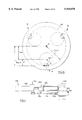
FIG. 3 is a scrap view of a portion of the object featured in FIG. 1, marked as 3 in FIG. 4;
FIG. 4 is a cross sectional view from the side, of part of the object feeder of FIG. 1;
FIG. 4a is a schematic view of a computer control system used as part of the object feeder of FIG. 1;
FIG. 5 is an end view of the embodiment of FIG. 1, taken along 5--5 of FIG. 4;
FIG. 6 is an end view of the embodiment of FIG. 1, taken along 6--6 of FIG. 4;
FIG. 7 is a perspective view of an object feeder having six pick-up heads in accordance with another embodiment of the present invention;
FIG. 8 is a plan view of the rear of the object feeder of FIG. 7;
FIG. 9 is a schematic view of another object feeder having six pick-up heads in accordance with another embodiment of the present invention in operation;
FIG. 10 is a schematic view of another object feeder having six pick-up heads in accordance with another embodiment of the present invention.
FIG. 11 is a schematic of the embodiment of FIG. 7, in operation.
FIG. 11a is a schematic view of the object feeder of FIGS. 7 and 11.
With reference to FIGS. 1-6, there is provided a rotary object feeder generally designated 18 having three identical planetary members 22a, 22b and 22c.
As shown in FIGS. 1, 3, 4, 5 and 6, there is provided a rotary object feeder 18 having a carrier member 20. Carrier member 20 is comprised of two circular disks 50 and 52. Disks 50 and 52 are made of a durable, rigid material such as steel or aluminum. A main shaft 36 is fixedly mounted to disk 52. Main shaft 36 is coaxial with a sun axis 30. A sun gear 38 is fixedly mounted on a support frame 16, adjacent to the rear side of disk 52 farthest from disk 50. Sun gear 38 is mounted on main shaft 36 and has a centre axis coincident with sun axis 30. Shaft 36 is rotatable relative to fixed sun gear 38.
Three identical planetary members 22a, 22b and 22c are mounted on carrier member 20. The three planetary members are mounted about planetary axes 32a, 32b and 32c at equal distances from sun axis 30, and at equal distances from each other. Only one planetary member 22a will be described herein in detail but it will be understood that planetary members 22b and 22c are identical in structure.
An idler gear 44a is rotatably mounted on disk 52 about shaft 33a so that it is freely rotatable about shaft 33a relative to disk 52 on the side of disk 52 farthest from disk 50. Idler gear 44a engages sun gear 38. Idler gear 44a also engages a planetary gear 46a. Planetary gear 46a is fixedly mounted on planetary shaft 48a, near an end of a planetary shaft 48a. Planetary shaft 48a extends through a cut away in circular disk 52, and through a cut away in lever 56a. A fixing shaft 58a is attached at one end to disk 54a and at another to lever 56a. Fixing shaft 58a acts as a counterweight mounted between disk 54a and lever 56a, diametrically opposite moon shaft 60a and is adapted in combination with the shaping of lever 56a to balance the weight of planetary system 22a about planetary shaft 48a, thereby providing a smooth balanced rotation about axis 32a.
A second end of planetary shaft 48a is fixedly attached to disk 54a at the centre of disk 54a. A housing 62a is fixedly mounted to the inner side of circular disk 52 and surrounds planetary shaft 48a. Ball bearings 84a are mounted in housing 62a and are interposed between planetary shaft 48a relative to housing 62a, thus permitting rotation of shaft 48a without housing 62a. Attached to the end of housing 62a proximate an inner side of lever 56a closest to lever 56a, is a planetary sun gear 70a. An idler gear 72a is rotatably mounted on an inner side of lever 56a closest to circular disk 54a on shaft 53a, and engages planetary sun gear 70a. A moon gear 74a is fixedly mounted to moon shaft 60a. Moon gear 74a is also engaged by idler gear 72a.
Mounted on shaft 42a atop suction cups 28a is a vacuum generator 102a. Vacuum generator 102a uses compressed air at one inlet and converts this compressed air into a stream of attracted air (ie. a vacuum). A vacuum generator suitable for use with this invention, is produced by Pisco™ Pneumatic Equipment, sold under model No. H10-016C or H10-018C. Vacuum generator 102a is connected to one end of hose 110a. The other end of hose 110a is connected to nib 104a. Hose 110a thus provides a means of air communication between vacuum generator 102a and nib 104a. Nib 104a extends in a direction along axis 32a from moon shaft 60a which is hollow. The hollow interior of moon shaft 60a forms an air passage 114a from an end connector 106a to nib 104a. End connector 106a is mounted on swivel joint 122a which permits end connector 106a to rotate about axis 34a. End connector 106a is connected to an end of hose 112a. The other end of hose 112a is connected to nib 108a. Nib 108a extends in a direction perpendicular to axis 32a from planetary shaft 48a which is also hollow. Planetary shaft 48a defines air passage 116a which extends from connector 117a to nib 108a. Connector 117a is mounted on swivel joint 121a permitting connector 117a to rotate about axis 32a. Hose 118a extends from connector 117a to an electronic control valve (not shown). A hose (also not shown) extends from the electronic control valve to manifold 124. The hose is connected to a nib (not shown) on the manifold. Corresponding electronic control valve 130b and nib 120b, connected to planetary member 22b, are however shown. Control valve 130b is connected by a hose to nib 120b and it controls the air flow to vacuum generator 102b. Nib 120b extends from manifold 124 and air passage 119b extends through hollow shaft 36. A suitable electronic control valve for use in this embodiment is sold by MAC™ Valves as part No. 111B/113B-111CA. Control valve 130b is connected to control wires (not shown) which extend to slip ring 37, as described below. A computer control system 140, as shown schematically in FIG. 4a provides control valve 130b with appropriate control signals to activate and de-activate the flow of compressed air to vacuum generator 102b. A connector 126 extending from an end of shaft 36 is connected to a source of air pressure (not shown).
In operation, a source of rotational power drives shaft 36 at an angular velocity of 107 1. A source of positive air pressure is fed to connector 126. Shaft 36 causes disk 52 and disk 50 along with planetary members 46a, 46b and 46c and their corresponding planetary axis, to rotate about the sun axis 30 at angular velocity ω1 and relative to sun gear 42. Consequently, idler gear 44a is driven about sun gear 38 and engages sun gear 38 to cause idler gear 44a to rotate about its shaft 33a in a direction the same as the direction of rotation of disk 52, as illustrated in FIG. 5. Planetary spur gear 46a is engaged by idler gear 44a and is rotated about its planetary axis 32a in the opposite direction as idler gear 44a and disc 52 at an angular velocity ω2. Planetary spur gear 46a, fixedly attached to planetary shaft 48a, causes planetary shaft 48a to rotate with spur gear 46a. Planetary shaft 48a, attached to disk 54a causes disk 54a to rotate along with planetary shaft 48a at an angular velocity ω2. As lever 56a is attached to disk 54a by fixing shaft 58a, lever 56a rotates with disk 54a about axis 32a. As disk 54a rotates about planetary axis 32a, so does moon shaft 60a and its moon axis 34a.
The gear ratios of sun gear 42, idler gear 44a and planetary spur gear 46a in this embodiment are chosen so that planetary system 21a and hence moon member 24a rotates 3 times about planetary axis 32a for each rotation of carrier 20 about its axis of rotation 30 (ie. ω3 /ω1 =3). The gear ratios of planetary sun gear 70a, planetary idler gear 72a and moon gear 74a are chosen so that moon member 24a rotates once about moon axis 34a for every rotation of sun member 22a about planetary axis 32a, but in the opposite direction (ie. ω2 /ω1 =-1)
As moon member 24a rotates in a direction opposite the direction of rotation of planetary member 22a at the same angular velocity as planetary member 22a, pick-up member 24a and suction cups 28a will always remain generally outwardly facing. Particularly, extension member 40a is mounted so that pick-up member 24a is always outwardly facing with respect to axis 30.
As carrier member 20 rotates, pick-up member 24a traverses a generally triangular trajectory 88 as shown in FIG. 2. At the vertices of this triangular trajectory 88, the velocity of suction cups 28a in a direction tangent to the rotation of the carrier is zero. This zero tangential velocity results from the contribution of the rotation of pick-up member 24a about axes 34a, 32a and 30. Zero tangential velocity at the vertices is achieved through a balancing choice of the ratios of rotation of planetary member 22a to carrier member 20; the positioning of axes of rotation 34a, 32a and 30 and the choice of the length of extension member 40a, as will be described later in further detail.
In FIG. 2a, the common portion of all three pic-kup members 26a, 26b and 26c is illustrated again, showing how the apparatus is arranged so that each pick up member will reach a vertex at the same instant in time.
Referring again to FIG. 2, as pick-up member 26a passes along its triangular trajectory, suction cups 28a pass through pick-up location 90. Located at pick-up location 90 is a carton magazine or feeder (not shown) for holding folded cartons. Suction cups 28a make contact with a top-most folded carton at pick-up location 90 while travelling in a direction perpendicular to the planar surface of the folded cartons. As pick-up member 24a passes through pick-up location 90, or shortly therebefore, an electric control valve (not shown) causes the inlet of vacuum generator 102a to be provided with pressurized air.
The electrical control valve is provided with control signals by means of control wires (not shown). These control wires are fixed relative to disc 52 make further contact with control wires 39 through slip ring 37. Control wires 39 are stationery relative to support 16 on the opposite side of slip ring 37. Thus, the control wires are stationary relative to disc 50 and mount 16. A suitable slip ring for use with this invention is sold by Litton™, as part No. AC4598.
The pressurized air is fed to vacuum generator 102a via air passages or cavities 126, 116a, 114a and hoses 118a and 112a. Vacuum generator 102a converts this pressurized air into a constant source of suction. This suction is fed to suction cups 28a, thereby causing a carton to adhere to suction cups 28a at pick-up location 90. In some applications, it is possible for the vacuum generator to be eliminated and a vacuum applied through the entire air system. The electrical actuator retains pressurized air at vacuum generator 102a and thereby suction at suction cup 28 until suction cup 28a reaches off-loading location 94. Suction cup 28a transports a folded carton from pick-up location 90 along trajectory 88 to operating location 92. As the folded carton travels from pick-up location 90, suction cup 28 remains outwardly facing because of suction cup 28a's rotation in an opposite direction and at an angular velocity equal to that of planetary member 22a.
As the shaft 36 and manifold 124 rotate, the distance between axis 32a and axis 30 does not change. Thus the distance between a nib on the manifold and its corresponding, connecting nibs on a planetary member does not change.
As connector 117a is attached by swivel joint 121a to swivel about axis 32a, hose 118a does not become twisted as manifold 124 rotates.
The same principle applies in respect of hose 112a between nib 108a and connector 106a, the latter which is adapted to swivel about axis 34a by means of swivel joint 122a, and in respect of hose 110a which links vacuum generator 102a to nib 104a. Nib 104a need not rotate about axis 34a because there is no movement of shaft 42a relative to shaft 60a.
Located at operating location 92 is an expansion unit (not shown). At operating location 92, the folded carton has zero tangential velocity. The carton expander, is located tangent to carrier 20 at operating location 92. The expander engages the folded carton and pulls the carton apart in a direction radial to carrier 20. Suction cup 28a further transports the unfolded carton along trajectory 88 to off-loading location 94. At off-loading location 94 the electromechanical actuator releases the negative pressure at suction cups 28a. Accordingly, the unfolded carton, having zero tangential velocity at off-loading location 94 is released. Located at off-loading location 94 is a transport mechanism (not shown) on which the unfolded carton is released. The unfolded carton is then transported by the transport mechanism away from the carton feeder to a location (not shown) where the carton is further processed.
Pick-up location 90, operating location 92 and off-loading location 94 are equally spaced from each other along the periphery of carrier 20. While pick-up member 26a follows trajectory 88, pick-up member 26c follows the same trajectory, but lags by 120° of rotation of carrier 20. Similarly, pick-up member 26c further lags 120° behind pick-up member 24b. Thus, when pick-up member 26a passes through pick-up location 90, pick-up member 24c passes through off-loading location 94, and pick-up member 24b passes through operating location 92. Vacuum generators 102b and 102c are actuated as pick-up members 26b and 26c pass through pick-up location 90. They are released as pick-up members 26b and 26c pass through off-loading location 94. Thus, for each rotation of carrier 20 about axis 30, three folded cartons are picked-up at pick-up location 90, expanded at operating location 92 and released at off-loading location 94.
With reference to FIG. 9, there is provided a rotary object feeder generally designated 218 having two sets of three identical planetary members; a first set 200a, 200b, 200c; and a second set 202a, 202b, and 202c.
The size of planetary members 200, 202 and the carrier member 220 are chosen, so that two sets of three planetary members may be mounted on a single carrier member.
In this embodiment, the six planetary members are arranged to function as two sets of three planetary members. The first set comprising planetary member 200a, 200b, and 200c having moon members 210a, 210b and 210c mounted thereon. Each moon member further comprises a pick-up member 206a, 206b and 206c. Each moon member 208a, 208b and 208c and 210a, 210b, 210c travels along trajectory 288 generally in the triangular pattern illustrated.
Each of the sets of moon members 208 and 210 rotate three times about a planetary axes for each rotation of carrier 220 about a sun axis, in an opposite direction as carrier 220. The pick-up members 204, travel along the trajectory 288 but lag pick-up members 206, by 60° of rotation of carrier member 220 about sun axis 230.
The vertices of the trajectory 288 are located at positions, 290, 292 and 294. Each of the pick-up members 204 and 206 pass through each vertex once for every rotation of carrier 220. Located at these vertices are a folded carton feeder, an operating unit and a transport unit respectively, as with the embodiment 1 shown in FIGS. 1-6. As in Embodiment 1 of FIGS. 1-6, a vacuum generator on each of members 204, and 206 is actuated as each of the pick-up members passes through the pick-up location 290. Suction cups forming pick-up members 204 and 206 pick-up a folded carton at pick-up location 290, transport it to operating location 292 where the folded carton is expanded, transport it to a further off-loading location 294 where it is released.
With the proper choice of angular velocities, position of axes and the proper mounting of the pick-up members, each suction cup will pass through pick-up 290, operating 292 and off-loading location 294 with zero tangential velocity.
It is possible that the general concept of the invention may be adapted to allow several pick-up members to each follow a different trajectory. In FIG. 10, each set of three pick-up members follow a different trajectory. Accordingly, in operation one set of pick-up members 200a, 200b, 200c follows a hypocycloidal trajectory. A second set of pick-up members 202a, 202b and 202c follows a hypocycloidal trajectory. The vertices of each trajectory are at different locations relative to the frame support (not shown). A rotary feeder according to such an embodiment may be adapted for two pick-up locations 280, 290, two operating locations 282, 292 and two off- loading locations 284, 294. Moon members 208a 208b, 208c and 210a, 210b, 210c follow paths 250 and 252, respectively. Each set of pick-up members 200 and 202 will pass along a generally hypocycloidal trajectory having one of the pick-up locations 280 or 290; one of the operating locations 282 or 292 and one of the off- loading locations 284 or 294 at its vertices. The rotary feeder may be used to feed six folded cartons from two different pick-up locations to two different off-loading locations for each rotation of carrier member 220.
The general inventive concept of the present invention, is not limited to rotary feeders having pick-up members rotating at three times the rate of a carrier member. FIGS. 7, 8, 11 and 11a, for example, illustrate a rotary object feeder having six pick-up members. In this embodiment, each planetary member 322a-322f is geared so that it rotates six times about planetary axes 332a-332f for each rotation of carrier member 320 about sun axis 330. The trajectory 388 of each planetary member is accordingly pseudo-hexagonal with six vertices, as shown in FIGS. 11 and 11a. As the relative radii and rates of rotation of carrier member 320 to planetary members 322a-322f, differs from the Embodiments 1, 2 and 3, the length of mounting shafts 326a-326f are chosen to achieve a minimum velocity of pick-up members 328a-328f at these vertices. Accordingly, the carton feeder may be adapted to have two sets of pick-up, operating, and off-loading locations, or it may be adapted to have a single pick-up and off-loading position with four operating positions, depending on the requirements of the particular application.
In the embodiment illustrated in FIG. 7, each object pick-up member will pick-up a folded carton from a magazine at a loading station 390. The folded carton is then rotated about the path shown in FIGS. 11 and 11a to a carton erection station 392. At station 392 a conventional carton erection apparatus is located, such as a vacuum source mounted on a reciprocating arm. The motion of the pick-up member may be such as to obviate the necessity for a separate reciprocating arm. Once the carton has been erected the carton is rotated to an unloading station where the vacuum at the suction cups in turned off, and the carton is allowed to be deposited onto a conveyor which removes the carton from the station. If the carton is stationary at the station 394, this carton feeder will be particularly suitable for use in combination with a hesitating carton loading system such as that disclosed in U.S. Pat. No. 5,371,995 issued Dec. 13, 1994 to Guttinger et al.
In FIG. 8 an alternate drive mechanism to the gearing mechanism described above, is shown for the planetary members in a 6 pick-up member rotary system. A sunwheel 438 is fixedly mounted to a support frame (not shown). Sunwheel 438 has mounted along its periphery a number of gear teeth. Disk 450 is mounted to shaft 436, and rotates relative to sunwheel 438. Gears 498 are rotatably mounted on one side of disk 450, and are connected to planetary members 322. Planetary members 322 are mounted on an opposite side of disk 450. A chain 499 is mounted about sunwheel 438, gears 498 and idler gears 497. In operation, shaft 436 is driven by a source of rotational power. Disk 450 rotates relative to sunwheel 438. Chain 499 travels along the periphery of sunwheel 438 and engages the gear teeth of sunwheel 438, and thereby moves relative to sunwheel 438. This motion of the chain, thus causes idler gears 497 and gears 498 to rotate. As gears 498 rotate, so do planetary members 322.
Various other types of driving mechanisms for rotary systems within the scope of the present invention are possible.
In each of the above embodiments the tangential velocity of each object-pick up member will be at or approach zero at the vertices of its trajectory. This is achieved through selection of a specific arrangement of mounting distances for planetary axis; moon axis; and pick-up member relative to a sun axis, and relative rates of rotation of carrier; planetary member and moon member. This selection may be even more clearly understood by reference to the following mathematical equations which are valid for the above embodiments:
Where,
Env /2=distance from the sun axis 30/330 to the circumferential arc created by the pick up point (eg.suction cup) of the pick-up member 28a when positioned at the vertices of its trajectory;
D/2=distance from the sun axis 30/330 to the planetary axis 32a/332a;
e=the distance from the planetary axes 32a/332a to the moon axes 34a/334a;
Vt =tangential velocity at a vertex of the path of the pick-up member;
The physical significance of these variables is shown is FIGS. 4 and 11.
The tangential velocity of the pick up point of a pick-up member Vt at a vertex of the path is calculated as follows:
V.sub.t =(E.sub.nv ×ω.sub.1)/2+{((E.sub.nv -D)×ω.sub.2 /2)+(((E.sub.nv -D)/2-e)×ω.sub.3)}
In order to obtain a minimal tangential velocity of pick-up member 28a at these vertices, Env, D, e, ω1, ω2 and ω3 must be chosen such that Vt =0 in the above equation.
Thus, in Embodiment 1 (see FIG. 2a):
Setting Vt =0; and choosing ω2 =-3ω1, and ω2 =-ω3 yields
e=Env /6
In Embodiment 4 (see FIG. 11a):
Setting Vt =0; and choosing ω2 =-6ω1, and ω2 =-ω3
e=Env /12
In both embodiments, D may be calculated by noting:
D=Env -2e
It will be understood by a person skilled in the art that many different variations are possible. Depending on the choice of sizes of the carrier and the planetary members, it is possible to construct a rotary feeder with an arbitrary number of carrier members. These carrier members may be adapted to rotate at any rate. By choosing the proper length of mounting shafts and/or extension members it is possible to balance the rotary feeder so that these pick-up members reach a minimum tangential velocity at the vertices of their trajectory(ies).
It will be further understood that the invention is not limited to the illustrations described and shown herein, which are deemed to be merely illustrative of the best modes of carrying out the invention, and which are susceptible to modification of form, size, arrangement of parts and details of operation. The invention, rather, is intended to encompass all such modifications which are within its spirit and scope as defined by the claims.
Claims (40)
1. A rotary object feeder, comprising:
a support;
a carrier member rotatably mounted to said support at a sun axis of rotation for rotation at a constant angular velocity ω1 about said sun axis;
a planetary member rotatably mounted to said carrier member at a planetary axis of rotation spaced from said sun axis of rotation at a distance D/2, said planetary member mounted for rotation at a constant planetary angular velocity ω2 about said planetary axis;
a moon member rotatably mounted to said planetary member at a moon axis of rotation spaced from said planetary axis of rotation at a distance e, said moon member mounted for rotation at a constant moon angular velocity ω3 about said moon axis;
an object pick-up member mounted to said moon member, having a pick-up surface at an outermost distance Env /2 from said sun axis;
said sun axis of rotation, said planetary axis of rotation and said moon axis of rotation being substantially parallel; and
wherein (Env ×ω1)/2+{((Env -D)×ω2 /2)+(((Env -D)/2-e)×ω3)} substantially equals zero.
2. The rotary object feeder of claim 1, further comprising a motor operably interconnected with said carrier member to rotate said carrier member, said planetary member and said moon member.
3. The rotary object feeder of claim 2, wherein (Env ×ω1)/2+{((Env -D)×ω2 /2)+(((Env -D)/2-e)×ω3)} equals zero.
4. A rotary object feeder, comprising:
a support;
a carrier member rotatably mounted to said support at a sun axis of rotation;
a planetary member rotatably mounted to said carrier member at a planetary axis of rotation spaced from said sun axis of rotation at a distance D/2;
a moon member rotatably mounted to said planetary member at a moon axis of rotation spaced from said planetary axis of rotation at a distance e;
an object pick-up member mounted to said moon member, having a pick-up surface at an outermost distance Env /2 from said sun axis;
said sun axis of rotation, said planetary axis of rotation and said moon axis of rotation being substantially parallel;
means for continuously rotating said carrier member at a constant carrier angular velocity ω1, said planetary member at a constant planetary angular velocity ω2, and said moon member at a constant moon angular velocity ω3,
wherein (Env ×ω1)/2+{((Env -D)×ω2 /2)+(((Env -D)/2-e)×ω3)} substantially equals zero.
5. The feeder of claim 4 wherein said means for rotating is arranged to rotate said planetary member in a direction opposite a direction of rotation of said sun member and said moon member.
6. The feeder of claim 5, wherein said means for rotating is arranged such that ω1 :ω2 =-1 and ω1 :ω3 =-1.
7. The feeder of claim 6 wherein said means for rotating comprises a drive train.
8. The feeder of claim 7 wherein said means for rotating is arranged to move said pick-up member through an operating location between said pick-up location and said off-loading location at a reduced velocity.
9. The feeder of claim 4 wherein said means for rotating is arranged such that said moon member angular velocity, ω3 is equal in magnitude to said planetary member angular velocity, ω2 and said planetary member angular velocity, ω2 and said moon member angular velocity are an integer multiple of said carrier member angular velocity, ω1.
10. The feeder of claim 9 wherein said pick-up member comprises a suction cup.
11. The feeder of claim 10 further comprising electrical control means to actuate said pick-up member to pick up said object at said pick-up location and to release said object at said off-loading location.
12. The feeder of claim 11 wherein said means for rotating comprises a motor and wherein said drive train comprises gearing operably connected between said motor and said carrier member, said planetary member and said moon member.
13. The feeder of claim 12 further comprising
a storage cartridge for holding folded cartons at said pick-up location;
means to erect said folded cartons located at said operating location;
a transport apparatus for transporting said cartons away from said feeder at said off-loading location;
wherein said pick-up member picks up a folded carton from said storage cartridge, said means to erect said folded cartons unfolds and erects said folded carton at said operating location and then said erected carton is transported to and then released at said off-loading location by said pick-up member.
14. The feeder of claim 4 wherein said pick-up member comprises a suction cup and said feeder further comprises an actuatable vacuum generator, said vacuum generator comprises an air input and an air output, said output in fluid communication with said suction cup, said generator for converting a source of positive air pressure supplied to said input to a vacuum at said output to provide a source of vacuum for said suction cup.
15. The feeder of claim 14 wherein:
said moon member has a hollow moon shaft with first and second ends, said hollow moon shaft having an elongated cavity, a first opening, and a second opening, said moon shaft having air communication through said elongated cavity between said first and second openings, said moon shaft positioned coaxially with said moon axis;
said planetary member has a hollow planetary shaft with first and second ends, said hollow planetary shaft having an elongated cavity with a first opening and a second opening, said planetary shaft having air communication through said cavity between said first and second openings of said cavity in said planetary shaft, said planetary shaft positioned coaxially with said planetary axis;
said carrier member being mounted on a hollow main shaft with a first end and a second end, said hollow main shaft having an elongated cavity with a first opening and a second opening, said shaft having air communication through said cavity between said first and second openings of said cavity of said main shaft, said main shaft being positioned coaxially with said sun axis;
and wherein said source of air pressure supplied to said vacuum generator comprises:
a first air pipe means connecting said vacuum generator to said first opening of said moon shaft;
a second air pipe means connecting said second opening of said moon shaft to said first opening of said planetary shaft, said second air pipe means having at least one swivel connection to permit said second air pipe means to swivel about at least one of said moon axis or said planetary axis;
a third air pipe means connecting said second opening of said planetary shaft to said first opening of said main shaft, said third air pipe means having at least one swivel connection to permit said third air pipe means to swivel about at least one of said planetary axis or said sun axis;
a source of air pressure connected to said second opening of said main shaft;
a control valve for controlling the vacuum for said suction cup.
16. A feeder as claimed in claim 15 wherein said first opening and said second opening of said cavity in said moon member are respectively positioned proximate said first and second ends of said moon member and said first opening and said second opening of said cavity in said planetary member are respectively positioned proximate said first and second ends of said planetary member.
17. The feeder of claim 4 wherein:
said pick-up member has a suction cup;
said moon member has a hollow moon shaft with first and second ends, said hollow moon shaft having an elongated cavity with a first opening and a second opening, said moon shaft having air communication through said cavity between said first and second openings of said cavity of said moon shaft, said moon shaft positioned coaxially with said moon axis;
said planetary member has a hollow planetary shaft with first and second ends, said planetary shaft having an elongated cavity with a first opening and a second opening, said shaft having air communication through said cavity between said first and second openings of said cavity of said planetary member, said planetary shaft positioned coaxially with said planetary axis;
said carrier member is mounted on a hollow main shaft with a first end and a second end, said main shaft having an elongated cavity with a first opening and a second opening, said main shaft having air communication through said cavity between said first and second openings of said cavity of said main shaft, said main shaft positioned coaxially with said sun axis;
an air communication system comprising:
a first air communication means connecting said suction cup and said first opening of said moon shaft;
a second air communication means connecting said second opening of said moon shaft to said first opening of said planetary shaft;
a third air communication means connecting said second opening of said planetary shaft to said first opening of said main shaft;
whereby a supply of air may be applied at said second opening of said main shaft to pass a supply of air through said air communication means and said cavities in said moon shaft, said planetary shaft and said main shaft to provide a vacuum at said suction cup.
18. The feeder of claim 17, further comprising a vacuum generator for converting a source of positive air pressure to a vacuum, disposed within said air communication system, such that if a supply of positively pressurized air is applied at said second opening of said main shaft, a vacuum is generated at said suction cup.
19. A feeder as claimed in claim 18 wherein said vacuum generator is included in said first air communication means.
20. A feeder as claimed in claim 17 wherein said first opening and said second opening of said cavity in said moon member are respectively positioned proximate said first and second ends of said moon member and said first opening and said second opening of said cavity in said planetary member are respectively positioned proximate said first and second ends of said planetary member.
21. A rotary object feeder, comprising:
a support;
a carrier member rotatably mounted to said support at a sun axis of rotation;
a planetary member rotatably mounted to said carrier member at
a planetary axis of rotation spaced from said sun axis of rotation at a distance D/2;
a moon member rotatably mounted to said planetary member at a moon axis of rotation spaced from said planetary axis of rotation at a distance e;
an object pick-up member mounted to said moon member, having a pick-up surface at an outermost distance Env /2 from said sun axis;
said sun axis of rotation, said planetary axis of rotation and said moon axis of rotation being substantially parallel;
means for continuously rotating said carrier member at a constant carrier angular velocity ω1, said planetary member at a constant planetary angular velocity ω2, and said moon member at a constant moon angular velocity ω3,
wherein Env, D and e are chosen so that (Env ×ω1)/2+{((Env -D)×ω2 /2)+((Env -D)/2-e)×ω3)} substantially equals zero.
22. A rotary object feeder comprising
a support;
a carrier member, rotatably mounted to said support at a sun axis of rotation;
a planetary member, rotatably mounted to said carrier member at a planetary axis of rotation, said planetary axis parallel to said sun axis and spaced therefrom;
an extension member rotatably mounted to said planetary member at a moon axis of rotation, said moon axis parallel to said planetary axis and spaced therefrom, said extension member mounted for rotation about said moon axis, and extending radially from said moon axis;
a shaft extending away from said extension member in a direction generally parallel to said moon axis and spaced from said moon axis; and
an object pick-up member mounted to said shaft having a pick-up surface for selective pick-up and release of objects proximate a periphery of said feeder, said pick-up surface extending toward said moor axis as said pick-up member picks-up and releases objects.
23. The rotary feeder of claim 22, further comprising a motor operably interconnected with said carrier member to rotate said carrier member, said planetary member and said extension member.
24. The rotary feeder of claim 23, wherein
said planetary axis is spaced from said sun axis a distance of D/2;
said moon axis is spaced from said planetary axis a distance of e;
said pick-up surface is spaced from said sun axis at a distance Env /2;
said carrier member, said planetary member and said moon member are adapted to rotate at rates of rotation ω1, ω2, and ω3 about said sun, planetary and moon axes, respectively; and wherein
(Env ×ω1)/2+{((Env -D)×ω2 /2)+(((Env -D)/2-e)×ω3)} substantially equals zero.
25. The rotary feeder of claim 22, wherein said object pick-up member is fixedly mounted to said shaft.
26. The rotary object feeder of claim 22 wherein
three substantially identical planetary members arc rotatably mounted to said carrier member at equal angular spacings about said sun axis,
each planetary member is associated with an extension member rotatably mounted to an associated planetary member at an associated moon axis and extending radially therefrom, each moon axis generally parallel to said sun axis,
each extension member is associated with a shaft extending from an associated extension member, in a direction generally parallel to an associated moon axis and spaced therefrom,
each shaft is associated with an object pick-up member mounted to an associated shaft,
each pick-up member has a pick-up surface for selective pick-up and release of objects proximate a periphery of said feeder, and
each pick-up member extends toward an associated moon axis as said each pick-up member picks-up and releases objects.
27. A rotary object feeder comprising
a support;
a carrier member, rotatably mounted to said support at a sun axis of rotation;
a planetary member, rotatably mounted to said carrier member at a planetary axis of rotation, said planetary axis parallel to said sun axis and spaced therefrom;
an extension member rotatably mounted to said planetary member at a moon axis of rotation, said moon axis parallel to said planetary axis and spaced therefrom, said extension member mounted for rotation about said moon axis, and extending radially from said moon axis;
a shaft extending away from said extension member in a direction generally parallel to said moon axis and spaced from said moon axis; and
an object pick up member mounted to said shaft having a pick-up surface extending toward said moon axis for selective pick-up and release of objects proximate a periphery of said feeder at a distance less than or equal to the distance of said moon axis from said sun axis.
28. The rotary feeder of claim 27, further comprising a motor operably interconnected with said carrier member to rotate said carrier member, said planetary member and said extension member.
29. The rotary feeder of claim 28, wherein
said planetary axis is spaced from said sun axis a distance of D/2;
said moon axis is spaced from said planetary axis a distance of e;
said pick-up surface is spaced from said sun axis at a distance Env /2;
said carrier member, said planetary member and said moon member are adapted to rotate at rates of rotation ω1, ω2, and ω3 about said sun, planetary and moon axes, respectively; and wherein
(Env ×ω1)/2+{((Env -D)×ω2 /2)+(((Env -D)/2-e)×ω3)} substantially equals zero.
30. The rotary feeder of claim 27, wherein said object pick-up member is fixedly mounted to said shaft.
31. The rotary object feeder of claim 27, wherein
a total of three substantially identical planetary members, are rotatably mounted to said carrier member at substantially equal angular spacings about said sun axis,
each planetary member is associated with an extension member rotatably mounted to an associated planetary member at an associated moon axis and extending radially therefrom, each moon axis generally parallel to said sun axis,
each extension member is associated with a shaft extending from an associated extension member, in a direction generally parallel to an associated moon axis and spaced therefrom,
each shaft is associated with an object pick-up member mounted to an associated shaft,
each pick-up member has a pick-up surface for selective pick-up and release of objects proximate a periphery of said feeder, and
each pick-up member extends toward an associated moon axis as said each pick-up member picks-up and releases objects.
32. A rotary object feeder, comprising:
(a) a support;
(b) a carrier member rotatably mounted to said support at a sun axis of rotation;
(c) first and second planetary systems, each planetary system comprising:
(i) a planetary member rotatably mounted to said carrier member at a planetary axis of rotation spaced from said sun axis of rotation;
(ii) a moon member rotatably mounted to said planetary member at a moon axis of rotation spaced from said planetary axis of rotation;
(iii) an object pick-up member mounted to said moon member;
said sun axis of rotation, and said planetary axes of rotation and said moon axes of rotation being substantially parallel;
means for continuously rotating said carrier member, said planetary members, and said moon members at fixed relative angular velocities, with at least one of said planetary member and said moon member in each planetary system rotating in a direction opposite to that of said carrier member, such that each of said pick-up members moves through a pick-up location at a reduced velocity relative to said support,
wherein a moon member, planetary member and object pick-up member of said first planetary system and a moon member, planetary member and object pick-up member of said second planetary system are mounted to said carrier member so that said object pick-up member of said first system travels along a first path about said sun axis, and said object pick-up member of said second planetary system travels along a second path about said sun axis, different than said first path.
33. A feeder as claimed in claim 32 wherein the angular velocities of said moon member and said planetary member of said first planetary system are the same as the respective angular velocities of said moon member and said planetary member of said second planetary system.
34. A feeder as claimed in claim 33, wherein the angular position of said moon member of said first planetary system is in phase with the angular position of said moon member of said second planetary system.
35. A feeder as claimed in claim 33 wherein said means for rotating is arranged to rotate said moon member of said first planetary system at a first moon member angular velocity and said planetary member of said first planetary system at a first planetary member angular velocity, and said moon member of said second planetary system at a second moon member angular velocity and said planetary member of said second planetary system at a second planetary member angular velocity, with said first moon member angular velocity being equal in magnitude to said first planetary member angular velocity, and said second moon member angular velocity being equal in magnitude to said second planetary member angular velocity, said first planetary member angular velocity being a first integer multiple of the carrier member angular velocity and said second planetary member angular velocity being a second integer multiple of the carrier member angular velocity.
36. A feeder as claimed in claim 35 wherein said first integer multiple and said second integer multiple are the same.
37. A rotary object feeder comprising
a support;
a carrier member, rotatably mounted to said support at a sun axis of rotation;
three planetary members, rotatably mounted to said carrier member at associated planetary axes of rotation, each planetary axis parallel to said sun axis and spaced therefrom;
an associated extension member rotatably mounted to each planetary member at an associated moon axis of rotation, each moon axis parallel to an associated planetary axis and spaced therefrom, each associated extension member mounted for rotation about an associated moon axis, and extending radially from an associated moon axis;
an associated shaft extending away from an associated extension member in a direction generally parallel to an associated moon axis and spaced therefrom; and
an object pick-up member mounted to each associated shaft having a pick-up surface for selective pick-up and release of objects proximate a periphery of said feeder, said pick-up surface extending toward said associated moon axis as said pick-up member picks-up and releases objects.
38. A method for feeding an object from a pick-up location to an off-loading location, comprising the steps of:
moving an object pick-up member having a pick-up surface along a trajectory by
(a) rotating said object pick-up member about a first axis of rotation at a constant object pick-up member angular velocity, ω3 ;
(b) rotating said first axis of rotation at a constant angular velocity ω2 about a second axis of rotation substantially parallel to said first axis of rotation and spaced a distance e therefrom;
(c) rotating said second axis of rotation at a constant angular velocity ω1 about a third axis of rotation substantially parallel to said second axis of rotation and spaced a distance D/2 from said second axis of rotation;
wherein said pick-up member is spaced from said first axis so that said pick-up surface is at an outermost distance of Env /2 from said third axis;
and wherein
(E.sub.nv ×ω.sub.1)/2+{((E.sub.nv -D)×ω.sub.2 /2)+(((E.sub.nv -D)/2-e)×ω.sub.3)} substantially equals zero;
said method further comprising:
picking up said object with said pick-up member at a pick-up location along said trajectory; and
releasing said object at an off-loading location along said trajectory.
39. The method of claim 38 wherein
said second axis of rotation is rotated in a direction opposite the direction of rotation of said first and third axes of rotation.
40. The method of claim 39 wherein ω2 =-ω3.
Priority Applications (1)
| Application Number | Priority Date | Filing Date | Title |
|---|---|---|---|
| US08/920,880 US5910078A (en) | 1995-09-28 | 1997-08-29 | Rotary object feeder |
Applications Claiming Priority (2)
| Application Number | Priority Date | Filing Date | Title |
|---|---|---|---|
| US53594595A | 1995-09-28 | 1995-09-28 | |
| US08/920,880 US5910078A (en) | 1995-09-28 | 1997-08-29 | Rotary object feeder |
Related Parent Applications (1)
| Application Number | Title | Priority Date | Filing Date |
|---|---|---|---|
| US53594595A Continuation | 1995-09-28 | 1995-09-28 |
Publications (1)
| Publication Number | Publication Date |
|---|---|
| US5910078A true US5910078A (en) | 1999-06-08 |
Family
ID=24136474
Family Applications (2)
| Application Number | Title | Priority Date | Filing Date |
|---|---|---|---|
| US08/828,589 Expired - Lifetime US5997458A (en) | 1995-09-28 | 1997-03-31 | Rotary object feeder |
| US08/920,880 Expired - Lifetime US5910078A (en) | 1995-09-28 | 1997-08-29 | Rotary object feeder |
Family Applications Before (1)
| Application Number | Title | Priority Date | Filing Date |
|---|---|---|---|
| US08/828,589 Expired - Lifetime US5997458A (en) | 1995-09-28 | 1997-03-31 | Rotary object feeder |
Country Status (3)
| Country | Link |
|---|---|
| US (2) | US5997458A (en) |
| EP (1) | EP0765736B1 (en) |
| DE (1) | DE69616930T2 (en) |
Cited By (29)
| Publication number | Priority date | Publication date | Assignee | Title |
|---|---|---|---|---|
| US6273242B1 (en) | 2000-02-29 | 2001-08-14 | Riverwood International Corporation | Rotary transfer apparatus with an in-line cam mechanism |
| US20020119879A1 (en) * | 2001-02-23 | 2002-08-29 | Thomas Wyss | Device for unfolding of folded boxes |
| US6594969B2 (en) * | 2000-07-24 | 2003-07-22 | Esatec Etudes Services Automatismes Techniques S.A. | Equipment for assembling products such as packages for compact discs |
| US6651800B2 (en) * | 2001-02-12 | 2003-11-25 | Langen Packaging Inc. | Object orientation system |
| US6659928B2 (en) | 2001-01-11 | 2003-12-09 | Rovema Verpackungsmaschinen Gmbh | Device for removing flat articles |
| US20040013508A1 (en) * | 2001-09-05 | 2004-01-22 | Kelly Ziegler | Rotary pick and place technology |
| US20040221549A1 (en) * | 2003-05-05 | 2004-11-11 | Peter Guttinger | Tray loader |
| US20040245697A1 (en) * | 2003-05-14 | 2004-12-09 | Heidelberger Druckmaschinen Ag | Sheet material feeder |
| EP1496000A2 (en) * | 2003-07-09 | 2005-01-12 | Langen Packaging Inc. | Rotary Object Feeder |
| EP1595828A2 (en) * | 2004-05-14 | 2005-11-16 | UHLMANN PAC-SYSTEME GmbH & Co. KG | Transfer device for packages |
| WO2006097831A1 (en) * | 2005-03-18 | 2006-09-21 | I.M.A. Industria Macchine Automatiche S.P.A. | Device for feeding carton blanks to a packaging machine |
| US20070022714A1 (en) * | 2005-07-29 | 2007-02-01 | Flagg Michael F | Carton feeder with positionable vacuum cups |
| EP1770030A2 (en) * | 2005-09-29 | 2007-04-04 | Robert Bosch Gmbh | Device for manipulating blister strips |
| US20070257416A1 (en) * | 2006-02-01 | 2007-11-08 | Graphic Packaging International, Inc. | Rotary carton feeder |
| WO2009083791A1 (en) * | 2008-01-03 | 2009-07-09 | Gdm S.P.A. | A unit for transferring products |
| US20100032882A1 (en) * | 2008-08-08 | 2010-02-11 | Mueller Martini Holding Ag | Device for supplying printed products to a processing section |
| CN103303708A (en) * | 2013-05-20 | 2013-09-18 | 浙江华岳包装机械有限公司 | Automatic picking and placing mechanism for film pasting of visible window of package box |
| US20140250651A1 (en) * | 2013-03-07 | 2014-09-11 | Cosmetic Laboratories Of America, Llc | Article assembly apparatus having rotary article pick and place |
| US20150031517A1 (en) * | 2013-07-23 | 2015-01-29 | G.D Societa' Per Azioni | Packing method and unit for folding a blank on a packing machine |
| TWI505901B (en) * | 2012-12-04 | 2015-11-01 | Ueno Seiki Co Ltd | Transfer equipment |
| ES2559304R1 (en) * | 2014-08-11 | 2016-06-23 | Monolab S.R.L. | Device for gripping a packaging case in a flattened configuration and opening it in a tubular configuration, and machine comprising said device. |
| CN107322982A (en) * | 2017-08-17 | 2017-11-07 | 海宁诚达机械有限公司 | A kind of suction mechanism of paper of paper cup making machine |
| FR3051773A1 (en) * | 2016-05-26 | 2017-12-01 | Construction Machines Automatiques Speciales | DEVICE FOR PACKAGING LOTS OF CARDS |
| JP2018012504A (en) * | 2016-07-19 | 2018-01-25 | 株式会社京都製作所 | Carton blank taking-out method and carton blank taking-out device |
| KR102032706B1 (en) | 2019-04-04 | 2019-11-08 | 주식회사 뉴팩코리아 | Rotary object feeder |
| US10850881B2 (en) | 2017-05-04 | 2020-12-01 | Afa Systems Ltd. | Method and apparatus for reconfiguring containers |
| WO2020252509A1 (en) | 2019-06-17 | 2020-12-24 | Knapp Ag | Vertical conveyor for a conveying installation |
| JP2021084634A (en) * | 2019-11-25 | 2021-06-03 | 株式会社旭金属 | Small bag supply apparatus |
| WO2023018416A1 (en) | 2021-08-12 | 2023-02-16 | R.A Jones & Co. | Rotary carton feeder |
Families Citing this family (38)
| Publication number | Priority date | Publication date | Assignee | Title |
|---|---|---|---|---|
| US5979889A (en) * | 1997-04-15 | 1999-11-09 | Heidelberger, Druckmaschinen Ag | Apparatus for generating a vacuum |
| IT1294186B1 (en) * | 1997-09-04 | 1999-03-22 | Gd Spa | METHOD AND UNIT OF FEEDING BLANK BLANKS TO A USING MACHINE |
| DE19909754A1 (en) * | 1999-03-05 | 2000-09-07 | Iwk Verpackungstechnik Gmbh | Device for transferring a folding box |
| GB2388107B (en) * | 2000-02-16 | 2004-05-12 | Hewlett Packard Co | Vacuum feeder for imaging device |
| US6467895B1 (en) * | 2000-02-16 | 2002-10-22 | Hewlett-Packard Company | Vacuum feeder for imaging device |
| US6557320B2 (en) * | 2001-08-31 | 2003-05-06 | Chen Hsien Chang | Compact disk packing machine |
| US20030181288A1 (en) * | 2002-03-21 | 2003-09-25 | Phillippe Gary E. | Drive efficiency enhancing system |
| US6837664B2 (en) | 2002-09-10 | 2005-01-04 | Douglas Machine, Inc. | Multiple head rotary set-up |
| WO2004087548A1 (en) * | 2003-03-31 | 2004-10-14 | Hewlett-Packard Development Company, L.P. | Rotor inverter |
| DE502005006128D1 (en) * | 2004-09-15 | 2009-01-15 | Ferag Ag | Method and device for separating flat objects from a horizontal stack |
| DE102005017962A1 (en) * | 2005-04-19 | 2006-10-26 | Iwk Verpackungstechnik Gmbh | Transfer device in a packaging machine |
| DE102005018391A1 (en) * | 2005-04-20 | 2006-10-26 | Uhlmann Pac-Systeme Gmbh & Co Kg | Device for removing, transporting, erecting and inserting folding boxes |
| US8302955B2 (en) | 2005-06-17 | 2012-11-06 | Hewlett-Packard Development Company, L.P. | Rotating vacuum fingers for removal of printing media from an impression drum |
| US7329218B2 (en) * | 2005-09-16 | 2008-02-12 | Raymond George Montague Kisch | Feed apparatus and method for feeding blanks into container forming machines |
| DE202006005312U1 (en) * | 2006-01-10 | 2006-06-01 | Wohlenberg Buchbindesysteme Gmbh | Device for tipping off a part of a signature to be separated from a stack |
| US20080072548A1 (en) | 2006-09-05 | 2008-03-27 | Peter Guttinger | Continuous loading system |
| US20120067004A1 (en) * | 2010-09-17 | 2012-03-22 | R.A. Jones & Co. Inc. | Orbital feeder |
| IT1401817B1 (en) * | 2010-09-20 | 2013-08-28 | Baumer Srl | ROTARY SYSTEM FOR TAKING, CARRYING AND FEEDING DIE CUTS |
| CN102085969B (en) * | 2010-09-25 | 2016-03-02 | 深圳市中钞科信金融科技有限公司 | Feed system |
| KR101205888B1 (en) | 2011-04-08 | 2012-11-28 | 주식회사 흥아기연 | Line-up device for packaging blister |
| US8870519B2 (en) | 2011-09-13 | 2014-10-28 | Graphic Packaging International, Inc. | Carton feeding system |
| US8807318B2 (en) * | 2011-09-20 | 2014-08-19 | International Business Machines Corporation | Multi-generational carrier platform |
| CN102627201A (en) * | 2012-04-10 | 2012-08-08 | 上海派莎实业有限公司 | Automatic sheet separator |
| US20150324893A1 (en) | 2012-04-24 | 2015-11-12 | H. J. Paul Langen | Method and system for order fulfilment |
| CN102795492B (en) * | 2012-08-27 | 2014-10-29 | 浙江上易机械有限公司 | Rotary paper suction mechanism |
| US9238558B2 (en) | 2012-09-12 | 2016-01-19 | Graphic Packaging International, Inc. | Reciprocating placer system |
| CA2980192C (en) | 2015-04-29 | 2019-05-07 | Graphic Packaging International, Inc. | Method and system for forming packages |
| CA2980354C (en) | 2015-04-29 | 2020-08-18 | Graphic Packaging International, Inc. | Method and system for forming packages |
| AU2016291771B2 (en) | 2015-07-14 | 2019-10-31 | Graphic Packaging International, Llc | Method and system for forming packages |
| CN106516814A (en) * | 2016-12-19 | 2017-03-22 | 深圳市乐彩智能卡科技有限公司 | Automatic card pasting device |
| WO2019032436A1 (en) | 2017-08-09 | 2019-02-14 | Graphic Packaging International, Llc | Method and system for forming packages |
| DE102019107451A1 (en) * | 2018-06-19 | 2019-12-19 | Windmöller & Hölscher Kg | Supply of negative pressure |
| MX2021000248A (en) | 2018-07-09 | 2021-03-25 | Graphic Packaging Int Llc | Method and system for forming packages. |
| WO2020097015A1 (en) | 2018-11-06 | 2020-05-14 | Graphic Packaging International LLC | Method and system for processing blanks for forming constructs |
| EP3917848A4 (en) | 2019-01-28 | 2022-11-02 | Graphic Packaging International, LLC | Reinforced package |
| US11390049B2 (en) | 2019-11-07 | 2022-07-19 | H. J. Paul Langen | Method and apparatus for erecting cartons |
| US11752723B2 (en) | 2019-11-07 | 2023-09-12 | H. J. Paul Langen | Method and apparatus for erecting cartons and for order fulfilment and packing |
| CN113232360A (en) * | 2021-04-14 | 2021-08-10 | 浙江新发现机械制造有限公司 | Rotary paper suction mechanism |
Citations (42)
| Publication number | Priority date | Publication date | Assignee | Title |
|---|---|---|---|---|
| US3026989A (en) * | 1959-08-17 | 1962-03-27 | Afico Sa | Machine for loading articles from the top and for transferring said articles |
| US3882998A (en) * | 1973-09-10 | 1975-05-13 | George T Hunter | Rotary feeder apparatus |
| US4194442A (en) * | 1977-03-18 | 1980-03-25 | Guglielmo Martelli | Device for picking up semi-rigid sheet-like elements from a magazine and transferring them onto a conveyor |
| FR2487310A1 (en) * | 1980-07-26 | 1982-01-29 | Weiersmueller Verpacksyst | Continuous pick=up mechanism for foils - has suction heads carried on rods rotated via levers, radial arms, and gears to move tangentially to foils |
| EP0132617A1 (en) * | 1982-07-06 | 1985-02-13 | R. A. JONES & CO. INC. | A transfer apparatus for articles |
| EP0134628A2 (en) * | 1983-08-09 | 1985-03-20 | H.J. Langen & Sons Limited | Carton opening mechanism |
| US4514181A (en) * | 1983-09-15 | 1985-04-30 | R. A. Jones & Co. Inc. | Apparatus for forming a flip top carton |
| EP0148345A2 (en) * | 1981-06-22 | 1985-07-17 | R. A. JONES & CO. INC. | Apparatus for feeding cartons from a stack |
| US4530686A (en) * | 1982-11-03 | 1985-07-23 | Everson William G | Rotary packaging technology |
| US4582315A (en) * | 1981-06-22 | 1986-04-15 | R. A. Jones & Co. Inc. | High speed carton feeder |
| US4596545A (en) * | 1982-07-06 | 1986-06-24 | R. A. Jones & Co. Inc. | Orbital feeder |
| US4601691A (en) * | 1984-11-19 | 1986-07-22 | R. A. Jones & Co. Inc. | Carton feeder |
| US4625575A (en) * | 1984-11-13 | 1986-12-02 | The Mead Corporation | Cam assembly for a feeder mechanism |
| US4643633A (en) * | 1984-02-17 | 1987-02-17 | Minnesota Automation | Rotary transfer device |
| CA1225109A (en) * | 1982-07-06 | 1987-08-04 | Jones (R.A.) & Co., Inc. | Orbital feeder |
| GB2192602A (en) * | 1986-06-27 | 1988-01-20 | Bradman Lake Ltd | Improvements relating to conveyors for closing cartons |
| US4773525A (en) * | 1986-05-23 | 1988-09-27 | Josef Uhlmann Maschinenfabrik Gmbh & Co. Kg | Transfer conveyor for packaging plant |
| US4830172A (en) * | 1985-12-17 | 1989-05-16 | Fmc Corporation | Rotary feeder |
| US4869486A (en) * | 1988-01-19 | 1989-09-26 | R. A. Jones & Co. Inc. | Method and apparatus for feeding carton blanks |
| US4871348A (en) * | 1986-12-19 | 1989-10-03 | Shibuya Kogyo Co. Ltd. | Carton erecting apparatus |
| US4902192A (en) * | 1988-05-19 | 1990-02-20 | Minnesota Automation, Inc. | Article control assembly for article transfer device |
| US4901843A (en) * | 1986-04-02 | 1990-02-20 | Minnesota Automation, Inc. | Advancing motion rotary apparatus |
| US4934682A (en) * | 1989-03-13 | 1990-06-19 | R. A. Jones & Co. Inc. | Apparatus for feeding cartons |
| US4998910A (en) * | 1987-04-21 | 1991-03-12 | R. A. Jones & Co. Inc. | Packaging container ejection apparatus |
| US5023974A (en) * | 1989-02-01 | 1991-06-18 | Conveyor Co. Of Australia Pty. Ltd. | Rotation method and apparatus |
| US5028044A (en) * | 1986-10-31 | 1991-07-02 | Wilhelm Fischer | Rotary feeder for blanks |
| US5037018A (en) * | 1988-06-10 | 1991-08-06 | Seikosha Co., Ltd. | Automatic feeder |
| CA2066837A1 (en) * | 1991-04-24 | 1992-10-25 | Pascal Portrait | Cam assembly and feeder mechanism for use in a packaging machine |
| US5176612A (en) * | 1991-12-13 | 1993-01-05 | The Mead Corporation | High speed erecting mechanism for sleeve type carton |
| US5188411A (en) * | 1991-01-24 | 1993-02-23 | John A. Blatt | Vacuum cup control apparatus |
| US5201560A (en) * | 1991-01-24 | 1993-04-13 | John A. Blatt | Vacuum cup control apparatus |
| US5215515A (en) * | 1992-11-05 | 1993-06-01 | Boris Bershadsky | Automatic carton opening and feeding apparatus with improved breaking and supporting mechanism |
| US5234314A (en) * | 1992-01-21 | 1993-08-10 | Riverwood International Corporation | Rotary hopper transfer mechanism |
| US5234304A (en) * | 1990-03-26 | 1993-08-10 | Japan Tobacco Inc. | Method and apparatus for workpiece installation |
| US5249916A (en) * | 1992-01-29 | 1993-10-05 | The Mead Corporation | Cam assembly and feeder mechanism for use in a packaging machine |
| US5254071A (en) * | 1990-07-20 | 1993-10-19 | Societe Anonyme Etudes Services Automatismes Techniques Esatec | Rotary feeder for the accurate placing of sheet elements on flat supports |
| EP0580958A1 (en) * | 1992-07-28 | 1994-02-02 | UHLMANN PAC-SYSTEME GmbH & Co. KG | Apparatus for taking, conveying, erecting and positionning folding boxes |
| US5371995A (en) * | 1993-05-20 | 1994-12-13 | H. J. Langen & Sons, Inc. | Hesitating carton loading machine |
| US5411464A (en) * | 1993-11-16 | 1995-05-02 | The Mead Corporation | Machine for erecting cartons having collapsible bottoms |
| US5431274A (en) * | 1993-06-02 | 1995-07-11 | Hms Label Specialties, Inc. | Rotary electronic profile placer |
| US5456570A (en) * | 1993-04-19 | 1995-10-10 | Bill Davis Engineering, Inc. | Rotary placer |
| US5603599A (en) * | 1994-09-28 | 1997-02-18 | Tetra Laval Holdings & Finance S.A. | Vacuum system |
Family Cites Families (6)
| Publication number | Priority date | Publication date | Assignee | Title |
|---|---|---|---|---|
| US4391372A (en) * | 1976-11-04 | 1983-07-05 | Industrial Dynamics Company, Ltd. | Vacuum starwheel |
| US4425075A (en) * | 1981-04-20 | 1984-01-10 | The Perkin-Elmer Corporation | Wafer aligners |
| DE3617259A1 (en) * | 1986-05-22 | 1987-11-26 | Haensel Otto Gmbh | METHOD AND DEVICE FOR THE TRANSFER OF PACKAGES, BAGS, BLISTERS OR THE LIKE FROM A PACKING MACHINE TO A CARTONING MACHINE |
| GB9017889D0 (en) * | 1990-08-15 | 1990-09-26 | Gersan Ets | Controlling a feed of objects |
| US5183145A (en) * | 1991-10-11 | 1993-02-02 | Sequa Corporation | Apparatus and method for automatically positioning valve means controlling the application of pressurized air to mandrels on a rotating carrier |
| US5421447A (en) * | 1992-04-07 | 1995-06-06 | Omega Design Corp. | High rate transfer wheel for orienting unscrambled containers |
-
1996
- 1996-09-25 DE DE69616930T patent/DE69616930T2/en not_active Expired - Lifetime
- 1996-09-25 EP EP96306957A patent/EP0765736B1/en not_active Expired - Lifetime
-
1997
- 1997-03-31 US US08/828,589 patent/US5997458A/en not_active Expired - Lifetime
- 1997-08-29 US US08/920,880 patent/US5910078A/en not_active Expired - Lifetime
Patent Citations (45)
| Publication number | Priority date | Publication date | Assignee | Title |
|---|---|---|---|---|
| US3026989A (en) * | 1959-08-17 | 1962-03-27 | Afico Sa | Machine for loading articles from the top and for transferring said articles |
| US3882998A (en) * | 1973-09-10 | 1975-05-13 | George T Hunter | Rotary feeder apparatus |
| US4194442A (en) * | 1977-03-18 | 1980-03-25 | Guglielmo Martelli | Device for picking up semi-rigid sheet-like elements from a magazine and transferring them onto a conveyor |
| FR2487310A1 (en) * | 1980-07-26 | 1982-01-29 | Weiersmueller Verpacksyst | Continuous pick=up mechanism for foils - has suction heads carried on rods rotated via levers, radial arms, and gears to move tangentially to foils |
| EP0148345A2 (en) * | 1981-06-22 | 1985-07-17 | R. A. JONES & CO. INC. | Apparatus for feeding cartons from a stack |
| US4582315A (en) * | 1981-06-22 | 1986-04-15 | R. A. Jones & Co. Inc. | High speed carton feeder |
| CA1204798A (en) * | 1982-07-06 | 1986-05-20 | Joseph D. Greenwell | Orbital feeder |
| EP0132617A1 (en) * | 1982-07-06 | 1985-02-13 | R. A. JONES & CO. INC. | A transfer apparatus for articles |
| CA1225109A (en) * | 1982-07-06 | 1987-08-04 | Jones (R.A.) & Co., Inc. | Orbital feeder |
| US4518301A (en) * | 1982-07-06 | 1985-05-21 | R. A. Jones & Co. Inc. | Orbital feeder |
| US4596545A (en) * | 1982-07-06 | 1986-06-24 | R. A. Jones & Co. Inc. | Orbital feeder |
| US4530686A (en) * | 1982-11-03 | 1985-07-23 | Everson William G | Rotary packaging technology |
| US4537587A (en) * | 1983-08-09 | 1985-08-27 | H. J. Langen & Sons Limited | Carton opening mechanism |
| EP0134628A2 (en) * | 1983-08-09 | 1985-03-20 | H.J. Langen & Sons Limited | Carton opening mechanism |
| US4514181A (en) * | 1983-09-15 | 1985-04-30 | R. A. Jones & Co. Inc. | Apparatus for forming a flip top carton |
| US4643633A (en) * | 1984-02-17 | 1987-02-17 | Minnesota Automation | Rotary transfer device |
| US4625575A (en) * | 1984-11-13 | 1986-12-02 | The Mead Corporation | Cam assembly for a feeder mechanism |
| US4601691A (en) * | 1984-11-19 | 1986-07-22 | R. A. Jones & Co. Inc. | Carton feeder |
| US4830172A (en) * | 1985-12-17 | 1989-05-16 | Fmc Corporation | Rotary feeder |
| US4901843A (en) * | 1986-04-02 | 1990-02-20 | Minnesota Automation, Inc. | Advancing motion rotary apparatus |
| US4773525A (en) * | 1986-05-23 | 1988-09-27 | Josef Uhlmann Maschinenfabrik Gmbh & Co. Kg | Transfer conveyor for packaging plant |
| GB2192602A (en) * | 1986-06-27 | 1988-01-20 | Bradman Lake Ltd | Improvements relating to conveyors for closing cartons |
| US5028044A (en) * | 1986-10-31 | 1991-07-02 | Wilhelm Fischer | Rotary feeder for blanks |
| US4871348A (en) * | 1986-12-19 | 1989-10-03 | Shibuya Kogyo Co. Ltd. | Carton erecting apparatus |
| US4998910A (en) * | 1987-04-21 | 1991-03-12 | R. A. Jones & Co. Inc. | Packaging container ejection apparatus |
| US4869486A (en) * | 1988-01-19 | 1989-09-26 | R. A. Jones & Co. Inc. | Method and apparatus for feeding carton blanks |
| US4902192A (en) * | 1988-05-19 | 1990-02-20 | Minnesota Automation, Inc. | Article control assembly for article transfer device |
| US5037018A (en) * | 1988-06-10 | 1991-08-06 | Seikosha Co., Ltd. | Automatic feeder |
| US5023974A (en) * | 1989-02-01 | 1991-06-18 | Conveyor Co. Of Australia Pty. Ltd. | Rotation method and apparatus |
| US4934682A (en) * | 1989-03-13 | 1990-06-19 | R. A. Jones & Co. Inc. | Apparatus for feeding cartons |
| US5234304A (en) * | 1990-03-26 | 1993-08-10 | Japan Tobacco Inc. | Method and apparatus for workpiece installation |
| US5254071A (en) * | 1990-07-20 | 1993-10-19 | Societe Anonyme Etudes Services Automatismes Techniques Esatec | Rotary feeder for the accurate placing of sheet elements on flat supports |
| US5201560A (en) * | 1991-01-24 | 1993-04-13 | John A. Blatt | Vacuum cup control apparatus |
| US5188411A (en) * | 1991-01-24 | 1993-02-23 | John A. Blatt | Vacuum cup control apparatus |
| CA2066837A1 (en) * | 1991-04-24 | 1992-10-25 | Pascal Portrait | Cam assembly and feeder mechanism for use in a packaging machine |
| US5176612A (en) * | 1991-12-13 | 1993-01-05 | The Mead Corporation | High speed erecting mechanism for sleeve type carton |
| US5234314A (en) * | 1992-01-21 | 1993-08-10 | Riverwood International Corporation | Rotary hopper transfer mechanism |
| US5249916A (en) * | 1992-01-29 | 1993-10-05 | The Mead Corporation | Cam assembly and feeder mechanism for use in a packaging machine |
| EP0580958A1 (en) * | 1992-07-28 | 1994-02-02 | UHLMANN PAC-SYSTEME GmbH & Co. KG | Apparatus for taking, conveying, erecting and positionning folding boxes |
| US5215515A (en) * | 1992-11-05 | 1993-06-01 | Boris Bershadsky | Automatic carton opening and feeding apparatus with improved breaking and supporting mechanism |
| US5456570A (en) * | 1993-04-19 | 1995-10-10 | Bill Davis Engineering, Inc. | Rotary placer |
| US5371995A (en) * | 1993-05-20 | 1994-12-13 | H. J. Langen & Sons, Inc. | Hesitating carton loading machine |
| US5431274A (en) * | 1993-06-02 | 1995-07-11 | Hms Label Specialties, Inc. | Rotary electronic profile placer |
| US5411464A (en) * | 1993-11-16 | 1995-05-02 | The Mead Corporation | Machine for erecting cartons having collapsible bottoms |
| US5603599A (en) * | 1994-09-28 | 1997-02-18 | Tetra Laval Holdings & Finance S.A. | Vacuum system |
Cited By (50)
| Publication number | Priority date | Publication date | Assignee | Title |
|---|---|---|---|---|
| US6273242B1 (en) | 2000-02-29 | 2001-08-14 | Riverwood International Corporation | Rotary transfer apparatus with an in-line cam mechanism |
| US6594969B2 (en) * | 2000-07-24 | 2003-07-22 | Esatec Etudes Services Automatismes Techniques S.A. | Equipment for assembling products such as packages for compact discs |
| US6659928B2 (en) | 2001-01-11 | 2003-12-09 | Rovema Verpackungsmaschinen Gmbh | Device for removing flat articles |
| US6651800B2 (en) * | 2001-02-12 | 2003-11-25 | Langen Packaging Inc. | Object orientation system |
| US6872176B2 (en) * | 2001-02-23 | 2005-03-29 | Rovema Verpackungsmaschinen Gmbh | Device for unfolding of folded boxes |
| US20020119879A1 (en) * | 2001-02-23 | 2002-08-29 | Thomas Wyss | Device for unfolding of folded boxes |
| US20040013508A1 (en) * | 2001-09-05 | 2004-01-22 | Kelly Ziegler | Rotary pick and place technology |
| US7273343B2 (en) | 2001-09-05 | 2007-09-25 | Graphic Packaging International, Inc. | Rotary pick and place technology |
| US7089717B2 (en) | 2003-05-05 | 2006-08-15 | Langen Packaging Inc. | Tray loader |
| US20040221549A1 (en) * | 2003-05-05 | 2004-11-11 | Peter Guttinger | Tray loader |
| US20040245697A1 (en) * | 2003-05-14 | 2004-12-09 | Heidelberger Druckmaschinen Ag | Sheet material feeder |
| US7306222B2 (en) * | 2003-05-14 | 2007-12-11 | Goss International Americas, Inc. | Sheet material feeder |
| US7081079B2 (en) | 2003-07-09 | 2006-07-25 | Langen Packaging Inc. | Rotary object feeder |
| EP1496000A3 (en) * | 2003-07-09 | 2005-02-16 | Langen Packaging Inc. | Rotary Object Feeder |
| US20050008470A1 (en) * | 2003-07-09 | 2005-01-13 | Petar Baclija | Rotary object feeder |
| US20060264311A1 (en) * | 2003-07-09 | 2006-11-23 | Langen Packaging Inc. | Rotary object feeder |
| US7326165B2 (en) | 2003-07-09 | 2008-02-05 | Langen Packaging Inc. | Rotary object feeder |
| EP1496000A2 (en) * | 2003-07-09 | 2005-01-12 | Langen Packaging Inc. | Rotary Object Feeder |
| EP1595828A2 (en) * | 2004-05-14 | 2005-11-16 | UHLMANN PAC-SYSTEME GmbH & Co. KG | Transfer device for packages |
| EP1595828A3 (en) * | 2004-05-14 | 2007-08-15 | UHLMANN PAC-SYSTEME GmbH & Co. KG | Transfer device for packages |
| US20080159844A1 (en) * | 2005-03-18 | 2008-07-03 | I.M.A. Industria Macchine Automatiche S.P.A. | Device For Feeding Carton Blanks To A Packaging Machine |
| CN101142123B (en) * | 2005-03-18 | 2010-09-01 | I.M.A.工业机械自动装置股份公司 | Device for feeding carton blanks to a packaging machine |
| US7603835B2 (en) | 2005-03-18 | 2009-10-20 | I.M.A. Industria Macchine Automatiche | Device for feeding carton blanks to a packaging machine |
| WO2006097831A1 (en) * | 2005-03-18 | 2006-09-21 | I.M.A. Industria Macchine Automatiche S.P.A. | Device for feeding carton blanks to a packaging machine |
| US20070022714A1 (en) * | 2005-07-29 | 2007-02-01 | Flagg Michael F | Carton feeder with positionable vacuum cups |
| EP1770030A3 (en) * | 2005-09-29 | 2008-05-21 | Robert Bosch Gmbh | Device for manipulating blister strips |
| EP1770030A2 (en) * | 2005-09-29 | 2007-04-04 | Robert Bosch Gmbh | Device for manipulating blister strips |
| US7695421B2 (en) | 2006-02-01 | 2010-04-13 | Graphic Packaging International, Inc. | Rotary carton feeder |
| US20070257416A1 (en) * | 2006-02-01 | 2007-11-08 | Graphic Packaging International, Inc. | Rotary carton feeder |
| WO2009083791A1 (en) * | 2008-01-03 | 2009-07-09 | Gdm S.P.A. | A unit for transferring products |
| US20100270126A1 (en) * | 2008-01-03 | 2010-10-28 | Gdm S.P.A. | unit for transferring products |
| US8281918B2 (en) | 2008-01-03 | 2012-10-09 | Gdm S.P.A. | Unit for transferring products |
| US20100032882A1 (en) * | 2008-08-08 | 2010-02-11 | Mueller Martini Holding Ag | Device for supplying printed products to a processing section |
| TWI505901B (en) * | 2012-12-04 | 2015-11-01 | Ueno Seiki Co Ltd | Transfer equipment |
| US20140250651A1 (en) * | 2013-03-07 | 2014-09-11 | Cosmetic Laboratories Of America, Llc | Article assembly apparatus having rotary article pick and place |
| CN103303708A (en) * | 2013-05-20 | 2013-09-18 | 浙江华岳包装机械有限公司 | Automatic picking and placing mechanism for film pasting of visible window of package box |
| US20150031517A1 (en) * | 2013-07-23 | 2015-01-29 | G.D Societa' Per Azioni | Packing method and unit for folding a blank on a packing machine |
| US9821526B2 (en) * | 2013-07-23 | 2017-11-21 | G. D. Societa' Per Azioni | Packing method and unit for folding a blank on a packing machine |
| ES2559304R1 (en) * | 2014-08-11 | 2016-06-23 | Monolab S.R.L. | Device for gripping a packaging case in a flattened configuration and opening it in a tubular configuration, and machine comprising said device. |
| FR3051773A1 (en) * | 2016-05-26 | 2017-12-01 | Construction Machines Automatiques Speciales | DEVICE FOR PACKAGING LOTS OF CARDS |
| JP2018012504A (en) * | 2016-07-19 | 2018-01-25 | 株式会社京都製作所 | Carton blank taking-out method and carton blank taking-out device |
| US10850881B2 (en) | 2017-05-04 | 2020-12-01 | Afa Systems Ltd. | Method and apparatus for reconfiguring containers |
| US11820542B2 (en) | 2017-05-04 | 2023-11-21 | Afa Systems Ltd. | Method and apparatus for reconfiguring containers |
| CN107322982A (en) * | 2017-08-17 | 2017-11-07 | 海宁诚达机械有限公司 | A kind of suction mechanism of paper of paper cup making machine |
| KR102032706B1 (en) | 2019-04-04 | 2019-11-08 | 주식회사 뉴팩코리아 | Rotary object feeder |
| WO2020252509A1 (en) | 2019-06-17 | 2020-12-24 | Knapp Ag | Vertical conveyor for a conveying installation |
| AT522732A1 (en) * | 2019-06-17 | 2021-01-15 | Knapp Ag | VERTICAL TRANSFORMER FOR A CONVEYOR |
| US11780680B2 (en) | 2019-06-17 | 2023-10-10 | Knapp Ag | Vertical conveyor for a conveying installation |
| JP2021084634A (en) * | 2019-11-25 | 2021-06-03 | 株式会社旭金属 | Small bag supply apparatus |
| WO2023018416A1 (en) | 2021-08-12 | 2023-02-16 | R.A Jones & Co. | Rotary carton feeder |
Also Published As
| Publication number | Publication date |
|---|---|
| EP0765736B1 (en) | 2001-11-14 |
| DE69616930T2 (en) | 2002-04-11 |
| DE69616930D1 (en) | 2001-12-20 |
| EP0765736A1 (en) | 1997-04-02 |
| US5997458A (en) | 1999-12-07 |
Similar Documents
| Publication | Publication Date | Title |
|---|---|---|
| US5910078A (en) | Rotary object feeder | |
| US7326165B2 (en) | Rotary object feeder | |
| CN101277884B (en) | Device for varying the separation pitch between articles conveyed | |
| US5025910A (en) | Rotary pad turner | |
| US5603599A (en) | Vacuum system | |
| JPH02502626A (en) | Device for transferring articles from the first conveyor to the second conveyor | |
| US7958801B2 (en) | Harmonic force generator for an active vibration control system | |
| CN1339010A (en) | Method and device for transportation | |
| GB2198711A (en) | Carton delivery apparatus | |
| US4530686A (en) | Rotary packaging technology | |
| JP3879044B2 (en) | A device for taking out the folded folding box from the storage chute and delivering it to the conveyor | |
| JP2006298491A (en) | Apparatus for take-out, transfer, assembly and insertion of folding box | |
| EP0642975B1 (en) | Device with a packaging wheel, for supplying sheets, in particular in cigarette packaging machines | |
| EP3802379B1 (en) | Carousel for transportation of articles | |
| KR970005736B1 (en) | Working mounting apparatus | |
| KR102193463B1 (en) | Extension spindle jig of spindle conveyor for transfer of workpiece | |
| KR960010032B1 (en) | Work mounting apparatus | |
| JPH09315412A (en) | Device for taking out box | |
| EP0534453B1 (en) | Method and apparatus for carrying workpiece in a continuous operation | |
| JP3225829B2 (en) | Article transfer device | |
| CA3228724A1 (en) | Rotary carton feeder | |
| JP3133791B2 (en) | Work transfer device | |
| JPH0590791A (en) | Work mounting apparatus | |
| JPH0590790A (en) | Work mounting apparatus | |
| JPS5917704B2 (en) | Transfer device for plate material |
Legal Events
| Date | Code | Title | Description |
|---|---|---|---|
| STCF | Information on status: patent grant |
Free format text: PATENTED CASE |
|
| FEPP | Fee payment procedure |
Free format text: PAYOR NUMBER ASSIGNED (ORIGINAL EVENT CODE: ASPN); ENTITY STATUS OF PATENT OWNER: LARGE ENTITY |
|
| FPAY | Fee payment |
Year of fee payment: 4 |
|
| AS | Assignment |
Owner name: LANGEN PACKAGING INC., CANADA Free format text: ASSIGNMENT OF ASSIGNORS INTEREST;ASSIGNOR:H.J. LANGEN INC.;REEL/FRAME:016513/0694 Effective date: 19980211 |
|
| FPAY | Fee payment |
Year of fee payment: 8 |
|
| FPAY | Fee payment |
Year of fee payment: 12 |