US5907796A - Cradle for an operating device - Google Patents
Cradle for an operating device Download PDFInfo
- Publication number
- US5907796A US5907796A US08/803,419 US80341997A US5907796A US 5907796 A US5907796 A US 5907796A US 80341997 A US80341997 A US 80341997A US 5907796 A US5907796 A US 5907796A
- Authority
- US
- United States
- Prior art keywords
- cradle
- connector
- locking member
- operating device
- locking
- Prior art date
- Legal status (The legal status is an assumption and is not a legal conclusion. Google has not performed a legal analysis and makes no representation as to the accuracy of the status listed.)
- Expired - Fee Related
Links
Images

Classifications
-
- B—PERFORMING OPERATIONS; TRANSPORTING
- B60—VEHICLES IN GENERAL
- B60R—VEHICLES, VEHICLE FITTINGS, OR VEHICLE PARTS, NOT OTHERWISE PROVIDED FOR
- B60R11/00—Arrangements for holding or mounting articles, not otherwise provided for
- B60R11/02—Arrangements for holding or mounting articles, not otherwise provided for for radio sets, television sets, telephones, or the like; Arrangement of controls thereof
- B60R11/0241—Arrangements for holding or mounting articles, not otherwise provided for for radio sets, television sets, telephones, or the like; Arrangement of controls thereof for telephones
-
- H—ELECTRICITY
- H04—ELECTRIC COMMUNICATION TECHNIQUE
- H04M—TELEPHONIC COMMUNICATION
- H04M1/00—Substation equipment, e.g. for use by subscribers
- H04M1/02—Constructional features of telephone sets
- H04M1/04—Supports for telephone transmitters or receivers
- H04M1/06—Hooks; Cradles
-
- B—PERFORMING OPERATIONS; TRANSPORTING
- B60—VEHICLES IN GENERAL
- B60R—VEHICLES, VEHICLE FITTINGS, OR VEHICLE PARTS, NOT OTHERWISE PROVIDED FOR
- B60R11/00—Arrangements for holding or mounting articles, not otherwise provided for
- B60R2011/0042—Arrangements for holding or mounting articles, not otherwise provided for characterised by mounting means
- B60R2011/0049—Arrangements for holding or mounting articles, not otherwise provided for characterised by mounting means for non integrated articles
- B60R2011/0064—Connection with the article
- B60R2011/0071—Connection with the article using latches, clips, clamps, straps or the like
Definitions
- the invention relates to electronic devices, such as mobile phones, and it is directed to a cradle having fastening means to retain a device in the cradle.
- the invention can be used for instance to attach a telephone to the dashboard of a car.
- a cradle is often used for a mobile phone so that the telephone can be inserted in the cradle.
- the cradle can be fastened e.g. to the dashboard of a car.
- the device has also some kind of locking means, so that the telephone is kept in its place also during movement.
- the cradle can also contain different connectors, with the aid of which the telephone can be connected for instance to the power supply of the vehicle and to an external telephone antenna of the vehicle or to a microphone or speaker external to the telephone.
- the cradle according to the invention has a locking member, with which a device inserted in the cradle is retained in its place. Then also the contacts operate reliably. Further the cradle has a connector, which moves as a response to the movement of the locking member. Thus, when the locking member is open, the connector can be hidden, whereby it will not be damaged or get dirty. Further, when the locking member moves into its locking position, the connector can retreat into the operating device against a connector in the operating device, whereby a particularly reliable contact is obtained.
- the cradle can be vertical, whereby it corresponds to the normal operating position of a mobile phone. If the depression then is at the base of the cradle the device cannot be easily dislodged by accident.
- the locking member can be such that it stays open by itself, whereby the operating device can be inserted in the cradle without opening the locking member.
- the locking member can function automatically when the operating device is inserted in the cradle, or it can be separately closed.
- the locking member can be at the opposite end or on the side regarding the depression, and it can be e.g. a catch pivoting about an axis.
- the connector can be in the stationary part of the frame or in the locking member. Its path of motion can be linear, whereby the construction is simple (for instance if it is desirable to have the connector and the counterpart to move into each other).
- the connector can have a linear motion controlled by the movement of the locking member, or an acting means, such as a spring actuated by the locking member, can be connected with the connector.
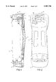
- FIG. 1 is a side elevation showing the cradle and a telephone inserted in it
- FIG. 2 is a view elevation showing the cradle and a telephone to be inserted in it
- FIG. 3 is a top view of the top support of the cradle.
- Main parts of the cradle are a back wall 1, a base support 2, a top support 3 and a locking nose 4.
- the cradle is intended to be fixed with suitable fixing means to the dashboard of a car, for instance.
- the base support 2 has a depression, into which the base of a telephone 5 is inserted. At the bottom of the depression there are contact terminals 6, which correspond to terminals 7 in the telephone, and with the aid of which the telephone in the cradle is connected to external circuits, such as a power supply, a microphone and a speaker. On the inner walls of the base support there are elastic paddings 8, which aid to keep the telephone firmly inserted.
- the top support 3 has a frame which laterally supports the telephone's top end.
- the locking nose 4 is pivoting attached to the back wall of the top support frame with the aid of a pin 9 and a spacer 10.
- the locking nose When the locking nose is in a lowered position the downwards extending supporting extension on the front wall of the nose is in front of the telephone preventing the telephone from moving forwards. Thus the operating device can not be accidentally dislodged.
- the locking nose When the locking nose is in its upper position the top end of the telephone can be pressed against the top support or pulled out from it when the base of the telephone at the same time is in the base support 2.
- a locking and releasing mechanism is connected with the locking nose 4, with which mechanism the nose can be locked in its lowered position whereby the telephone 5 is locked in the cradle, and with which the nose can be released so that it can pivot to its upper position whereby the telephone can be removed from the cradle or inserted in it.
- the mechanism has a button 11 projecting from the front wall of the locking nose, and squeezing the button can release the mechanism.
- a return spring 12 pushing the button into its front position is connected with the button 11 of the locking and releasing mechanism.
- On both sides of the button there are sliding pins 13.
- the body of the locking nose has a groove 14 in the form of a lying V opening towards the front.
- a lift spring 15 is connected with the locking nose 4, and this spring is located below the pivot pin 9 and pushes the nose forwards from the back wall of the cradle.
- the construction can also be realized without lifting spring 15 of the locking nose 4, whereby fewer parts are required and the telephone will not be immediately dislodged when the locking is released.
- the top support 3 further comprises a connector 16 and the telephone 5 has a corresponding connector 17.
- the connector is particularly a so called RF connector, through which the telephone can be connected to an external antenna.
- the connector may also serve other functions.
- the connector 16 moves according to the movement of the locking nose 4, so that also the connector moves up when the nose moves up.
- the connector located at the top is hidden within the top support 3, whereby it is well protected against dirt or mechanical damage.
- the connector moves downwards to rest against the connector 17 of the telephone.
- the connector 16 moves along linear path.
- the top support 3 has a vertical motion path 18 for the connector
- the connector has on its side towards the locking nose 4 a sliding pin 19
- the locking nose has a guiding groove 20 in the corresponding place.
- the guiding groove is formed so that the guiding groove forces the connector into vertical movement when the locking nose pivots (i.e., in a side elevation the groove is forward sloping).
Abstract
Description
Claims (11)
Applications Claiming Priority (2)
| Application Number | Priority Date | Filing Date | Title |
|---|---|---|---|
| FI960831 | 1996-02-23 | ||
| FI960831A FI960831A (en) | 1996-02-23 | 1996-02-23 | Actuator stand |
Publications (1)
| Publication Number | Publication Date |
|---|---|
| US5907796A true US5907796A (en) | 1999-05-25 |
Family
ID=8545519
Family Applications (1)
| Application Number | Title | Priority Date | Filing Date |
|---|---|---|---|
| US08/803,419 Expired - Fee Related US5907796A (en) | 1996-02-23 | 1997-02-20 | Cradle for an operating device |
Country Status (3)
| Country | Link |
|---|---|
| US (1) | US5907796A (en) |
| FI (1) | FI960831A (en) |
| GB (1) | GB2310564B (en) |
Cited By (21)
| Publication number | Priority date | Publication date | Assignee | Title |
|---|---|---|---|---|
| EP1093972A2 (en) * | 1999-10-21 | 2001-04-25 | Andreas Peiker | Holder for a radiotelephone |
| EP1164055A2 (en) | 2000-06-12 | 2001-12-19 | Nokia Mobile Phones Ltd. | Mounting system for portable telephone |
| EP1233598A1 (en) * | 2001-02-19 | 2002-08-21 | Sony International (Europe) GmbH | Holding device for a mobile telecommunication means |
| US20050113150A1 (en) * | 2002-03-08 | 2005-05-26 | Thomas Schlegel | Hands-free device for operating mobile telephones in motor vehicles with a module-changing mechanism |
| US7072689B1 (en) * | 2000-06-05 | 2006-07-04 | Qualcomm, Inc. | Lock and release mechanism for a wireless device |
| US20070121279A1 (en) * | 2005-11-25 | 2007-05-31 | Motorola, Inc. | Translating axes slide mechanism |
| US20070197271A1 (en) * | 2004-05-27 | 2007-08-23 | Pasi Haikola | Holding Device For A Cellular Phone |
| DE102007028763A1 (en) * | 2007-06-22 | 2008-12-24 | Audi Ag | Mobile terminal e.g. laptop, connecting device arrangement for vehicle, has evaluation and control unit for producing diagnosis information signal, where information signal is transmitted to vehicle control device over diagnosis line |
| US20100097239A1 (en) * | 2007-01-23 | 2010-04-22 | Campbell Douglas C | Mobile device gateway systems and methods |
| US20100100310A1 (en) * | 2006-12-20 | 2010-04-22 | Johnson Controls Technology Company | System and method for providing route calculation and information to a vehicle |
| US20100144284A1 (en) * | 2008-12-04 | 2010-06-10 | Johnson Controls Technology Company | System and method for configuring a wireless control system of a vehicle using induction field communication |
| US20100220250A1 (en) * | 2006-12-20 | 2010-09-02 | Johnson Controls Technology Company | Remote display reproduction system and method |
| US8029443B2 (en) | 2003-07-15 | 2011-10-04 | Abbott Diabetes Care Inc. | Glucose measuring device integrated into a holster for a personal area network device |
| US8460243B2 (en) | 2003-06-10 | 2013-06-11 | Abbott Diabetes Care Inc. | Glucose measuring module and insulin pump combination |
| US20170018156A1 (en) * | 2015-07-15 | 2017-01-19 | Kum Oh Electronics Co., Ltd. | Anti-theft apparatus for mobile device |
| US9776577B2 (en) | 2012-08-13 | 2017-10-03 | Jeffrey D. Carnevali | Modular electronics platform |
| USD890740S1 (en) | 2020-01-17 | 2020-07-21 | Davinci Ii Csj, Llc | Appliance holder |
| USD907029S1 (en) | 2020-04-09 | 2021-01-05 | Davinci Ii Csj, Llc | Device holder and stand combination |
| US10933815B1 (en) | 2020-02-04 | 2021-03-02 | Da Vinci II CSJ, LLC | Apparatus for holding mobile device |
| US10963417B2 (en) | 2004-06-04 | 2021-03-30 | Abbott Diabetes Care Inc. | Systems and methods for managing diabetes care data |
| US11534089B2 (en) | 2011-02-28 | 2022-12-27 | Abbott Diabetes Care Inc. | Devices, systems, and methods associated with analyte monitoring devices and devices incorporating the same |
Families Citing this family (1)
| Publication number | Priority date | Publication date | Assignee | Title |
|---|---|---|---|---|
| WO2008058523A1 (en) * | 2006-11-13 | 2008-05-22 | Peiker Acustic Gmbh & Co. Kg | Holding apparatus for an electronic appliance |
Citations (16)
| Publication number | Priority date | Publication date | Assignee | Title |
|---|---|---|---|---|
| US3818150A (en) * | 1972-04-27 | 1974-06-18 | Nitsuko Ltd | Telephone switchhook with bi-directional operation |
| US3889071A (en) * | 1973-10-01 | 1975-06-10 | Lockheed Aircraft Corp | Handset cradle |
| US4360714A (en) * | 1980-09-02 | 1982-11-23 | Burroughs Corporation | Telephone moveable cradle lock |
| US4406928A (en) * | 1981-04-02 | 1983-09-27 | International Telephone And Telegraph Corporation | Multi-purpose telephone holder apparatus |
| US4957264A (en) * | 1989-02-08 | 1990-09-18 | Nokia-Mobira Oy | Mounting base for a telephone device, such as a mobile telephone |
| US5016851A (en) * | 1989-02-03 | 1991-05-21 | Nokia Mobile Phones | Attachment system for the holder of the operating device of a radiophone |
| US5040712A (en) * | 1989-02-03 | 1991-08-20 | Nokia Mobile Phones Ltd. | Mounting system for car telephone |
| DE4008618A1 (en) * | 1990-03-17 | 1991-09-26 | Philips Patentverwaltung | Holder for car radio telephone handpiece - has spring and spring-loaded pressure block cooperating with opposite end faces of telephone handpiece |
| GB2243049A (en) * | 1990-04-12 | 1991-10-16 | Technophone Ltd | Holder for portable telephone |
| US5121863A (en) * | 1989-02-03 | 1992-06-16 | Nokia Mobile Phones Ltd. | Rack for telephone hand set |
| US5189698A (en) * | 1990-04-12 | 1993-02-23 | Nokia Mobile Phones Ltd. | Holder suitable for preventing inadvertent detachment of a telephone or its operating handpiece held by the holder |
| EP0590450A1 (en) * | 1992-09-30 | 1994-04-06 | Robert Bosch Gmbh | Telephone handset support |
| US5333176A (en) * | 1992-04-30 | 1994-07-26 | Murata Machinery, Ltd. | Cellular hand held portable speakerphone system having an interface adapter |
| DE4405506A1 (en) * | 1994-02-21 | 1995-08-31 | Aeg Mobile Communication | Holder for a hand-held radio telephone |
| US5555448A (en) * | 1995-02-27 | 1996-09-10 | Delco Electronics Corporation | Combined wireless/wired phone handset system |
| US5597102A (en) * | 1994-05-18 | 1997-01-28 | Nokia Mobile Phones Ltd. | Attachment device for a mobile station |
-
1996
- 1996-02-23 FI FI960831A patent/FI960831A/en unknown
-
1997
- 1997-02-05 GB GB9702291A patent/GB2310564B/en not_active Expired - Fee Related
- 1997-02-20 US US08/803,419 patent/US5907796A/en not_active Expired - Fee Related
Patent Citations (16)
| Publication number | Priority date | Publication date | Assignee | Title |
|---|---|---|---|---|
| US3818150A (en) * | 1972-04-27 | 1974-06-18 | Nitsuko Ltd | Telephone switchhook with bi-directional operation |
| US3889071A (en) * | 1973-10-01 | 1975-06-10 | Lockheed Aircraft Corp | Handset cradle |
| US4360714A (en) * | 1980-09-02 | 1982-11-23 | Burroughs Corporation | Telephone moveable cradle lock |
| US4406928A (en) * | 1981-04-02 | 1983-09-27 | International Telephone And Telegraph Corporation | Multi-purpose telephone holder apparatus |
| US5121863A (en) * | 1989-02-03 | 1992-06-16 | Nokia Mobile Phones Ltd. | Rack for telephone hand set |
| US5016851A (en) * | 1989-02-03 | 1991-05-21 | Nokia Mobile Phones | Attachment system for the holder of the operating device of a radiophone |
| US5040712A (en) * | 1989-02-03 | 1991-08-20 | Nokia Mobile Phones Ltd. | Mounting system for car telephone |
| US4957264A (en) * | 1989-02-08 | 1990-09-18 | Nokia-Mobira Oy | Mounting base for a telephone device, such as a mobile telephone |
| DE4008618A1 (en) * | 1990-03-17 | 1991-09-26 | Philips Patentverwaltung | Holder for car radio telephone handpiece - has spring and spring-loaded pressure block cooperating with opposite end faces of telephone handpiece |
| GB2243049A (en) * | 1990-04-12 | 1991-10-16 | Technophone Ltd | Holder for portable telephone |
| US5189698A (en) * | 1990-04-12 | 1993-02-23 | Nokia Mobile Phones Ltd. | Holder suitable for preventing inadvertent detachment of a telephone or its operating handpiece held by the holder |
| US5333176A (en) * | 1992-04-30 | 1994-07-26 | Murata Machinery, Ltd. | Cellular hand held portable speakerphone system having an interface adapter |
| EP0590450A1 (en) * | 1992-09-30 | 1994-04-06 | Robert Bosch Gmbh | Telephone handset support |
| DE4405506A1 (en) * | 1994-02-21 | 1995-08-31 | Aeg Mobile Communication | Holder for a hand-held radio telephone |
| US5597102A (en) * | 1994-05-18 | 1997-01-28 | Nokia Mobile Phones Ltd. | Attachment device for a mobile station |
| US5555448A (en) * | 1995-02-27 | 1996-09-10 | Delco Electronics Corporation | Combined wireless/wired phone handset system |
Cited By (36)
| Publication number | Priority date | Publication date | Assignee | Title |
|---|---|---|---|---|
| EP1093972A3 (en) * | 1999-10-21 | 2003-04-02 | Andreas Peiker | Holder for a radiotelephone |
| US6775561B1 (en) | 1999-10-21 | 2004-08-10 | Andreas Peiker | Holder for radio telephone |
| EP1093972A2 (en) * | 1999-10-21 | 2001-04-25 | Andreas Peiker | Holder for a radiotelephone |
| US7072689B1 (en) * | 2000-06-05 | 2006-07-04 | Qualcomm, Inc. | Lock and release mechanism for a wireless device |
| EP1164055A2 (en) | 2000-06-12 | 2001-12-19 | Nokia Mobile Phones Ltd. | Mounting system for portable telephone |
| EP1233598A1 (en) * | 2001-02-19 | 2002-08-21 | Sony International (Europe) GmbH | Holding device for a mobile telecommunication means |
| US6993368B2 (en) * | 2002-03-08 | 2006-01-31 | Audioton Kabelwerk Gmbh Zweigniederlassung Scheinfeld | Hands-free device for operating mobile telephones in motor vehicles with a module-changing mechanism |
| US20050113150A1 (en) * | 2002-03-08 | 2005-05-26 | Thomas Schlegel | Hands-free device for operating mobile telephones in motor vehicles with a module-changing mechanism |
| US8460243B2 (en) | 2003-06-10 | 2013-06-11 | Abbott Diabetes Care Inc. | Glucose measuring module and insulin pump combination |
| US8029443B2 (en) | 2003-07-15 | 2011-10-04 | Abbott Diabetes Care Inc. | Glucose measuring device integrated into a holster for a personal area network device |
| US7756552B2 (en) * | 2004-05-27 | 2010-07-13 | Nokia Corporation | Holding device for a cellular phone |
| US20070197271A1 (en) * | 2004-05-27 | 2007-08-23 | Pasi Haikola | Holding Device For A Cellular Phone |
| US10963417B2 (en) | 2004-06-04 | 2021-03-30 | Abbott Diabetes Care Inc. | Systems and methods for managing diabetes care data |
| US11182332B2 (en) | 2004-06-04 | 2021-11-23 | Abbott Diabetes Care Inc. | Systems and methods for managing diabetes care data |
| US11507530B2 (en) | 2004-06-04 | 2022-11-22 | Abbott Diabetes Care Inc. | Systems and methods for managing diabetes care data |
| US20070121279A1 (en) * | 2005-11-25 | 2007-05-31 | Motorola, Inc. | Translating axes slide mechanism |
| US8634033B2 (en) | 2006-12-20 | 2014-01-21 | Johnson Controls Technology Company | Remote display reproduction system and method |
| US20100220250A1 (en) * | 2006-12-20 | 2010-09-02 | Johnson Controls Technology Company | Remote display reproduction system and method |
| US20100100310A1 (en) * | 2006-12-20 | 2010-04-22 | Johnson Controls Technology Company | System and method for providing route calculation and information to a vehicle |
| US9430945B2 (en) | 2006-12-20 | 2016-08-30 | Johnson Controls Technology Company | System and method for providing route calculation and information to a vehicle |
| US9587958B2 (en) | 2007-01-23 | 2017-03-07 | Visteon Global Technologies, Inc. | Mobile device gateway systems and methods |
| US20100097239A1 (en) * | 2007-01-23 | 2010-04-22 | Campbell Douglas C | Mobile device gateway systems and methods |
| DE102007028763A1 (en) * | 2007-06-22 | 2008-12-24 | Audi Ag | Mobile terminal e.g. laptop, connecting device arrangement for vehicle, has evaluation and control unit for producing diagnosis information signal, where information signal is transmitted to vehicle control device over diagnosis line |
| DE102007028763B4 (en) * | 2007-06-22 | 2009-12-31 | Audi Ag | Device arrangement for connection of a mobile terminal in a vehicle |
| US20120184200A1 (en) * | 2007-12-05 | 2012-07-19 | Johnson Controls Technology Company | System and method for configuring a wireless control system of a vehicle using induction field communication |
| US8843066B2 (en) * | 2007-12-05 | 2014-09-23 | Gentex Corporation | System and method for configuring a wireless control system of a vehicle using induction field communication |
| US10045183B2 (en) | 2008-12-04 | 2018-08-07 | Gentex Corporation | System and method for configuring a wireless control system of a vehicle |
| US9324230B2 (en) | 2008-12-04 | 2016-04-26 | Gentex Corporation | System and method for configuring a wireless control system of a vehicle using induction field communication |
| US20100144284A1 (en) * | 2008-12-04 | 2010-06-10 | Johnson Controls Technology Company | System and method for configuring a wireless control system of a vehicle using induction field communication |
| US11534089B2 (en) | 2011-02-28 | 2022-12-27 | Abbott Diabetes Care Inc. | Devices, systems, and methods associated with analyte monitoring devices and devices incorporating the same |
| US9776577B2 (en) | 2012-08-13 | 2017-10-03 | Jeffrey D. Carnevali | Modular electronics platform |
| US20170018156A1 (en) * | 2015-07-15 | 2017-01-19 | Kum Oh Electronics Co., Ltd. | Anti-theft apparatus for mobile device |
| US9659471B2 (en) * | 2015-07-15 | 2017-05-23 | Kum Oh Electronics Co., Ltd. | Anti-theft apparatus for mobile device |
| USD890740S1 (en) | 2020-01-17 | 2020-07-21 | Davinci Ii Csj, Llc | Appliance holder |
| US10933815B1 (en) | 2020-02-04 | 2021-03-02 | Da Vinci II CSJ, LLC | Apparatus for holding mobile device |
| USD907029S1 (en) | 2020-04-09 | 2021-01-05 | Davinci Ii Csj, Llc | Device holder and stand combination |
Also Published As
| Publication number | Publication date |
|---|---|
| GB2310564A (en) | 1997-08-27 |
| FI960831A0 (en) | 1996-02-23 |
| FI960831A (en) | 1997-08-24 |
| GB9702291D0 (en) | 1997-03-26 |
| GB2310564B (en) | 2000-01-12 |
Similar Documents
| Publication | Publication Date | Title |
|---|---|---|
| US5907796A (en) | Cradle for an operating device | |
| US6785567B2 (en) | Radio device holder including device locking member and tray having tray locking member | |
| US6370362B1 (en) | Slide cover for a communication unit | |
| US6963756B2 (en) | Electronic equipment comprising a retractable screen | |
| US5828750A (en) | Positive holding rack | |
| US6829495B2 (en) | Battery pack locking apparatus for a mobile telephone | |
| JPH10513614A (en) | Cradles for mobile phones or other electrical devices | |
| ITMI950293A1 (en) | PORTABLE MOBILE PHONE SUPPORT | |
| US20080142651A1 (en) | Cradle for Mobile Phones and Ejector Device Thereof | |
| EP1439685B1 (en) | Flip-phone cover | |
| KR200261161Y1 (en) | a hands free cradle of a phone | |
| US6212276B1 (en) | Hanging latch hook mechanism for telephones | |
| EP1672888A1 (en) | Accessory with speaker module for portable wireless terminal | |
| JP3373411B2 (en) | Station and information processing apparatus using the same | |
| US6775561B1 (en) | Holder for radio telephone | |
| US20020061733A1 (en) | Unfolding apparatus for foldable electronic device | |
| EP1220367B1 (en) | Electronic device, accessory for electronic device and support element | |
| EP1233598A1 (en) | Holding device for a mobile telecommunication means | |
| JPH01212052A (en) | Collapsible telephone set | |
| CN214203541U (en) | Switch convenient for wiring and mounting | |
| KR200307484Y1 (en) | Hands-free cradle for cellular phone | |
| KR20020010027A (en) | Battery cover automatic opening/closing device for portable radiotelephone | |
| KR200155804Y1 (en) | Structure of hook-switch actuator of telephone | |
| KR100365854B1 (en) | Antenna device for portable radiotelephone | |
| JP2001023723A (en) | Interface connector plug |
Legal Events
| Date | Code | Title | Description |
|---|---|---|---|
| AS | Assignment |
Owner name: NOKIA MOBILE PHONES LTD., FINLAND Free format text: ASSIGNMENT OF ASSIGNORS INTEREST;ASSIGNORS:MATCHETT, BOB;HEBBLEWHITE, MALCOLM;REEL/FRAME:008499/0220 Effective date: 19961125 |
|
| FPAY | Fee payment |
Year of fee payment: 4 |
|
| FPAY | Fee payment |
Year of fee payment: 8 |
|
| FEPP | Fee payment procedure |
Free format text: PAYOR NUMBER ASSIGNED (ORIGINAL EVENT CODE: ASPN); ENTITY STATUS OF PATENT OWNER: LARGE ENTITY |
|
| REMI | Maintenance fee reminder mailed | ||
| LAPS | Lapse for failure to pay maintenance fees | ||
| STCH | Information on status: patent discontinuation |
Free format text: PATENT EXPIRED DUE TO NONPAYMENT OF MAINTENANCE FEES UNDER 37 CFR 1.362 |
|
| FP | Lapsed due to failure to pay maintenance fee |
Effective date: 20110525 |