US5907596A - Calling party identification device with message function - Google Patents
Calling party identification device with message function Download PDFInfo
- Publication number
- US5907596A US5907596A US08/602,003 US60200396A US5907596A US 5907596 A US5907596 A US 5907596A US 60200396 A US60200396 A US 60200396A US 5907596 A US5907596 A US 5907596A
- Authority
- US
- United States
- Prior art keywords
- telephone
- line
- caller
- caller identification
- coupled
- Prior art date
- Legal status (The legal status is an assumption and is not a legal conclusion. Google has not performed a legal analysis and makes no representation as to the accuracy of the status listed.)
- Expired - Fee Related
Links
Images


Classifications
-
- H—ELECTRICITY
- H04—ELECTRIC COMMUNICATION TECHNIQUE
- H04M—TELEPHONIC COMMUNICATION
- H04M1/00—Substation equipment, e.g. for use by subscribers
- H04M1/57—Arrangements for indicating or recording the number of the calling subscriber at the called subscriber's set
- H04M1/575—Means for retrieving and displaying personal data about calling party
-
- H—ELECTRICITY
- H04—ELECTRIC COMMUNICATION TECHNIQUE
- H04M—TELEPHONIC COMMUNICATION
- H04M1/00—Substation equipment, e.g. for use by subscribers
- H04M1/66—Substation equipment, e.g. for use by subscribers with means for preventing unauthorised or fraudulent calling
- H04M1/663—Preventing unauthorised calls to a telephone set
-
- H—ELECTRICITY
- H04—ELECTRIC COMMUNICATION TECHNIQUE
- H04M—TELEPHONIC COMMUNICATION
- H04M1/00—Substation equipment, e.g. for use by subscribers
- H04M1/64—Automatic arrangements for answering calls; Automatic arrangements for recording messages for absent subscribers; Arrangements for recording conversations
- H04M1/65—Recording arrangements for recording a message from the calling party
- H04M1/658—Means for redirecting recorded messages to other extensions or equipment
Definitions
- the present invention relates generally to caller identification devices, and more particularly, is directed to a caller identification device with a message function.
- CPID calling party identification
- caller identification devices do not provide any additional information that indicates the caller's intentions. Accordingly, a caller identification device is not sufficient to replace the "while you were out” message slips.
- U.S. Reissue Pat. No. 31,789 to Hashimoto discloses a device for displaying a caller's telephone number while the telephone is ringing. Although Hashimoto does disclose providing the device with an electronic printer in order to print out a record of the telephone numbers of calls received while the owner of the device is absent, there is no disclosure of using the device to relay messages from the caller to the owner.
- U.S. Pat. No. 4,582,956 to Doughty discloses a method and apparatus for displaying CPID information at a called telephone station during the silent interval between ringing.
- Doughty describes an apparatus that can be used to receive alphanumeric messages from a caller, but these messages are not stored. Rather, these messages are only displayed during the silent interval.
- LCD liquid crystal display
- the present invention comprises a caller identification device attachable to a telephone line and having a message function.
- the device includes a line interface coupled to the telephone line, a ring detector coupled to the telephone line for detecting rings of an incoming telephone call, and a line monitor coupled to the telephone line for receiving an incoming telephone call signal (which can be caller ID information, or DTMF signals or the like) from the telephone line in an on-hook state.
- the device further includes a caller identification detector, coupled to the line monitor, for detecting caller identification information including at least the caller's telephone number when the line monitor receives an incoming telephone call signal, and a speech synthesizer coupled to the line interface for generating and transmitting speech signals along the telephone line.
- the device still further includes a remote detector coupled to the line monitor for detecting a remote command tone signal.
- a controller is provided for controlling the line interface to seize the telephone line when the ring detector detects rings of an incoming call. Prior to the line interface seizing the telephone line, the controller controls recording of the caller identification information detected by the caller identification detector. The controller also causes the speech synthesizer to generate and transmit to the caller a menu of spoken options prompting the caller to enter a remote command tone signal corresponding to a message when the line interface seizes the telephone line, and records the message corresponding to the entered remote command tone signal detected by the remote detector.
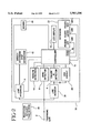
- FIG. 1 is a block diagram of a caller identification device in accordance with one embodiment of the present invention
- FIG. 2 is a block diagram of a caller identification device in accordance with another embodiment of the present invention.
- FIG. 3 is a block diagram of a caller identification device in accordance with still another embodiment of the present invention.
- the present invention relates to calling party identification (CPID) devices, and more particularly, to a caller identification device that, in addition to storing the caller's name and telephone number, will prompt the caller to enter a number that corresponds to a particular message.
- the caller enters the number using the keypad of the telephone from which he is calling.
- the owner of the caller identification device upon his or her return, can then retrieve the caller's name, telephone number and the general nature of the call.
- Most caller identification devices have certain components, namely a ring detector, a caller identification modem, a liquid crystal display (LCD) to display the name and number of the caller, and some kind of controller that contains random access memory (RAM) to store identification information for later recall.
- the present invention adds a speech synthesizer and a dual tone multi-frequency (DTMF) receiver to the basic caller identification device to provide enhanced usability.
- the controller, the RAM and the speech synthesizer may be combined into a single integrated circuit (IC), such as the TSP50C10/11 chip manufactured by Texas Instruments.
- a caller identification device 20 is connected in parallel with a telephone 26 to a telephone line 2.
- device 20 could be incorporated into a specially designed telephone (not shown).
- Telephone line 2 is coupled to a line interface circuit 4, a ring detector 6 and a line monitor 24, all part of caller identification device 20.
- Ring detector 6 monitors telephone line 2 for the detection of ringing signals sent from a telephone company central office.
- Line monitor 24 is a high input impedance circuit that allows device 20 to monitor telephone line 2 without being in an off-hook state.
- line monitor 24 is coupled to a caller identification detector 8 which is used to detect information about the caller, that is, the caller's name and telephone number.
- Line monitor 24 is further coupled to a remote detector 10, and allows remote detector 10 to detect DTMF tones on the telephone line 2 that are entered by a caller.
- the output port of line monitor 24 and the input port of caller identification detector 8 are coupled to the input port of VOX circuit 25.
- the output port of VOX circuit 25 is coupled to controller 14.
- Line interface circuit 4 is coupled to a speech synthesis/DTMF generator 12 which is used to play a message to the caller (described in more detail hereinbelow) after a certain number of rings have gone unanswered.
- a controller 14 of device 20 controls or monitors the operations of line interface circuit 4, ring detector 6, caller identification detector 8, remote detection circuit 10, speech synthesis/DTMF generator 12 and a keyboard 22.
- controller 14 monitors ring detector 6, waiting for an incoming ring.
- the caller identification detector 8 detects CPID information, that is, the caller's name and telephone number. This information is stored in a RAM 16 coupled to controller 14, and is displayed on a LCD 18. If a predetermined number of rings, such as four, occurs with no answer, controller 14 commands line interface circuit 4 to seize telephone line 2, and then instructs speech synthesis/DTMF generator 12 to play a message on telephone line 2. This message instructs the caller to enter a number, that is, a DTMF tone corresponding to the option that the caller wishes to select.
- the caller can then enter a DTMF tone, using his or her telephone keypad, to choose a desired option or options.
- Remote detection circuit 10 detects the DTMF tone entered by the caller and sends it to controller 14 which implements the command.
- the remote detection circuit 10 can be provided with a voice signal detector in addition to or in place of a DTMF tone detector. The information obtained from the caller would then be indicated on the LCD display 18.
- speech synthesizer/DTMF generator 12 would prompt the caller to enter the month, date and time of the proposed meeting.
- speech synthesis/DTMF generator 12 pages the owner of the device 20 and transmits the number that was obtained by the caller identification operation.
- speech synthesis/DTMF generator 12 sends the caller's telephone number to the owner's pager unit via a pager service.
- LCD 18 displays the information obtained from the caller via the DTMF tone as well as the caller's name and telephone number.
- the owner of device 20 can then obtain this information upon his or her return. If desired, as discussed below, the owner of device 20 has the option of disabling the paging feature by pressing a "Pager/Off" key.
- Keyboard 22 is provided with at least the following three keys: Pager/Off key 22A, Pager Learn key 22B, and Pager Test key 22C. These keys allow device 20 to be programmed to page the owner of the device 20 and transmit CPID information to the owner's paging device.
- Pager Learn key 22B is pressed when the owner wants to program his or her pager number into device 20. After pressing Pager Learn key 22B, the owner then takes off-hook any telephone 26 which is connected to the same telephone line 2 as device 20, and dials his or her pager service on the touch tone keypad of telephone 26. After the owner's pager service has answered and prompts him to enter the telephone number to be displayed, the owner then presses a predetermined series of keys (such as * * *) to end the learning process. Controller 14 stores the telephone number of the pager service in memory 16 as well as the duration of the pauses between the dialed digits and the predetermined series of keys.
- the predetermined series of tones that are entered after the owner's pager number instruct controller 14 to pause and then cause the speech synthesis/DTMF generator 12 to transmit a caller's telephone number obtained from caller identification detector 8, as described above, via the pager service to the owner's pager unit.
- the pager feature use can be made in the present invention of the pager system disclosed in copending U.S. application Ser. No. 08/588,123 filed Jan. 18, 1996 (inventor: Mark J. Karnowski), now U.S. Pat. No. 5,761,271, and assigned to the same assignee as the present application, the entire contents of which are incorporated herein by reference.
- Pager Test key 22C allows the owner to test the device after his pager number has been programmed into it. Controller 14 accesses the pager service and then transmits a predetermined test code, such as "123", via the speech synthesis/DTMF generator 12 to the owner's pager. In this manner, the owner can be assured that device 20 is programmed correctly.
- Pager/Off key 22A allows the owner to selectively set the device to forward all calls to his pager.
- device 20 is set to Pager mode, every time a telephone call is received, CPID information will be transmitted to the owner's pager.
- the Pager mode is turned off by pressing the Pager/Off key 22A, only CPID information of those caller's that select the "page" option 6 from the synthesized voice menu will be transmitted to the owner's pager.
- a modem 28 is coupled between controller 14 and line interface 4, and device 30 can transmit the name, telephone number and a message of a caller, such as "CALL BACK", to a pager via modem 28, in response to a caller's responses.
- a caller identification device 40 in accordance with still another embodiment of the present invention is shown. Again, elements corresponding to those of FIG. 1 are identified by the same reference numerals and a detailed description of the common elements will not be described for the sake of brevity.
- a record/playback unit 35 is coupled between controller 14 and line interface 4.
- caller identification device 40 is integrated into a telephone answering device (TAD).
- TAD telephone answering device
- the synthesized voice menu can be replaced by the owner's recorded greeting.
- the TAD transmits CPID information to the owner's pager every time a call is received, whether or not the caller leaves a message on record/playback unit 35.
- the Pager mode is turned off by means of Pager/Off key 22A, the TAD records messages as usual.
- a modem 28 can be optionally added between the controller 14 and the line interface 4, and works in the same manner as discussed above with reference to FIG. 2.
Abstract
Description
Claims (17)
Priority Applications (1)
| Application Number | Priority Date | Filing Date | Title |
|---|---|---|---|
| US08/602,003 US5907596A (en) | 1996-02-15 | 1996-02-15 | Calling party identification device with message function |
Applications Claiming Priority (1)
| Application Number | Priority Date | Filing Date | Title |
|---|---|---|---|
| US08/602,003 US5907596A (en) | 1996-02-15 | 1996-02-15 | Calling party identification device with message function |
Publications (1)
| Publication Number | Publication Date |
|---|---|
| US5907596A true US5907596A (en) | 1999-05-25 |
Family
ID=24409583
Family Applications (1)
| Application Number | Title | Priority Date | Filing Date |
|---|---|---|---|
| US08/602,003 Expired - Fee Related US5907596A (en) | 1996-02-15 | 1996-02-15 | Calling party identification device with message function |
Country Status (1)
| Country | Link |
|---|---|
| US (1) | US5907596A (en) |
Cited By (48)
| Publication number | Priority date | Publication date | Assignee | Title |
|---|---|---|---|---|
| US6094475A (en) * | 1996-12-21 | 2000-07-25 | Samsung Electronics Co., Ltd. | Apparatus and method for controlling automatic answering service of portable telephone in a base station unit |
| US6192116B1 (en) * | 1998-08-31 | 2001-02-20 | Lucent Technologies Inc. | System and method for generating CID/CIDCW information with a user inputted message |
| US6212265B1 (en) * | 1998-01-27 | 2001-04-03 | Darin Duphorne | Method and apparatus for electronic mail notification |
| DE19949532A1 (en) * | 1999-10-14 | 2001-04-19 | Deutsche Telekom Ag | Telephone answering device for analogue telecommunications terminal identifies caller number for storage together with date and time of incoming call |
| US6289070B1 (en) | 1997-04-22 | 2001-09-11 | Silicon Laboratories, Inc. | Digital isolation system with ADC offset calibration including coarse offset |
| US6297755B2 (en) | 1997-04-22 | 2001-10-02 | Silicon Laboratories, Inc. | Analog isolation system with digital communication across a capacitive barrier |
| US6298133B1 (en) * | 1997-04-22 | 2001-10-02 | Silicon Laboratories, Inc. | Telephone line interface architecture using ringer inputs for caller ID data |
| US6307891B1 (en) | 1997-04-22 | 2001-10-23 | Silicon Laboratories, Inc. | Method and apparatus for freezing a communication link during a disruptive event |
| US6323796B1 (en) | 1997-04-22 | 2001-11-27 | Silicon Laboratories, Inc. | Digital isolation system with ADC offset calibration |
| US6330330B2 (en) | 1997-04-22 | 2001-12-11 | Silicon Laboratories, Inc. | External resistor and method to minimize power dissipation in DC holding circuitry for a communication system |
| US6359983B1 (en) | 1997-04-22 | 2002-03-19 | Silicon Laboratories, Inc. | Digital isolation system with data scrambling |
| US6385235B1 (en) | 1997-04-22 | 2002-05-07 | Silicon Laboratories, Inc. | Direct digital access arrangement circuitry and method for connecting to phone lines |
| US6389061B1 (en) | 1997-04-22 | 2002-05-14 | Silicon Laboratories Inc. | Isolation system with digital communication across a capacitive barrier |
| US6389134B1 (en) | 1997-04-22 | 2002-05-14 | Silicon Laboratories, Inc. | Call progress monitor circuitry and method for a communication system |
| US6408034B1 (en) | 1997-04-22 | 2002-06-18 | Silicon Laboratories, Inc. | Framed delta sigma data with unlikely delta sigma data patterns |
| US6430229B1 (en) | 1997-04-22 | 2002-08-06 | Silicon Laboratories Inc. | Capacitive isolation system with digital communication and power transfer |
| US6442271B1 (en) | 1997-04-22 | 2002-08-27 | Silicon Laboratories, Inc. | Digital isolation system with low power mode |
| US6442213B1 (en) | 1997-04-22 | 2002-08-27 | Silicon Laboratories Inc. | Digital isolation system with hybrid circuit in ADC calibration loop |
| US6456712B1 (en) | 1997-04-22 | 2002-09-24 | Silicon Laboratories Inc. | Separation of ring detection functions across isolation barrier for minimum power |
| WO2002078299A2 (en) * | 2001-03-22 | 2002-10-03 | Koninklijke Philips Electronics N.V. | Telephone memory aid |
| US6480602B1 (en) | 1997-04-22 | 2002-11-12 | Silicon Laboratories, Inc. | Ring-detect interface circuitry and method for a communication system |
| US6498825B1 (en) | 1997-04-22 | 2002-12-24 | Silicon Laboratories Inc. | Digital access arrangement circuitry and method for connecting to phone lines having a DC holding circuit with programmable current limiting |
| US20020196913A1 (en) * | 2001-06-25 | 2002-12-26 | Bellsouth Intellectual Property Corporation | Visual caller identification |
| US6504864B1 (en) | 1997-04-22 | 2003-01-07 | Silicon Laboratories Inc. | Digital access arrangement circuitry and method for connecting to phone lines having a second order DC holding circuit |
| US20030022718A1 (en) * | 2001-07-17 | 2003-01-30 | Salerno Victor J. | Remote wagering system |
| US6516024B1 (en) | 1997-04-22 | 2003-02-04 | Silicon Laboratories Inc. | Digital access arrangement circuitry and method for connecting to phone lines having a DC holding circuit with low distortion and current limiting |
| US6587560B1 (en) | 1997-04-22 | 2003-07-01 | Silicon Laboratories Inc. | Low voltage circuits powered by the phone line |
| EP1383300A1 (en) * | 2002-07-17 | 2004-01-21 | Timothy M. Harris | Telephone call messaging device |
| US6738613B1 (en) * | 1998-05-08 | 2004-05-18 | Matsushita Electric Industrial Co., Ltd. | Telephone set having automatic incoming-call acknowledgement detection |
| US20040209661A1 (en) * | 2003-04-17 | 2004-10-21 | Gregorin Adam C. | System and method for employee incentive game |
| US20040209605A1 (en) * | 2003-04-18 | 2004-10-21 | Urban Blake R. | Caller ID Messaging |
| US20050036604A1 (en) * | 1997-04-22 | 2005-02-17 | Silicon Laboratories Inc. | Direct digital access arrangement circuitry and method for connecting DSL circuitry to phone lines |
| US20050094788A1 (en) * | 2003-10-30 | 2005-05-05 | International Business Machines Corporation | Method and system for enhancement of caller identification |
| US6917671B1 (en) | 2001-10-25 | 2005-07-12 | At&T Corp. | Network-based method for notification of the best time to call |
| US7218713B1 (en) | 2003-04-15 | 2007-05-15 | Silicon Laboratories Inc. | Telephone line interface for DAA circuitry |
| US20090202058A1 (en) * | 2008-02-07 | 2009-08-13 | Mamoon Tariq Khan | Telephonic automated action system |
| US7672444B2 (en) | 2003-12-24 | 2010-03-02 | At&T Intellectual Property, I, L.P. | Client survey systems and methods using caller identification information |
| US7945253B2 (en) | 2003-11-13 | 2011-05-17 | At&T Intellectual Property I, L.P. | Method, system, and storage medium for providing comprehensive originator identification services |
| US7978841B2 (en) | 2002-07-23 | 2011-07-12 | At&T Intellectual Property I, L.P. | System and method for gathering information related to a geographical location of a caller in a public switched telephone network |
| US7978833B2 (en) | 2003-04-18 | 2011-07-12 | At&T Intellectual Property I, L.P. | Private caller ID messaging |
| US8019064B2 (en) | 2001-08-14 | 2011-09-13 | At&T Intellectual Property I, L.P. | Remote notification of communications |
| US8139758B2 (en) | 2001-12-27 | 2012-03-20 | At&T Intellectual Property I, L.P. | Voice caller ID |
| US8155287B2 (en) | 2001-09-28 | 2012-04-10 | At&T Intellectual Property I, L.P. | Systems and methods for providing user profile information in conjunction with an enhanced caller information system |
| US8160226B2 (en) | 2007-08-22 | 2012-04-17 | At&T Intellectual Property I, L.P. | Key word programmable caller ID |
| US8195136B2 (en) | 2004-07-15 | 2012-06-05 | At&T Intellectual Property I, L.P. | Methods of providing caller identification information and related registries and radiotelephone networks |
| US8243909B2 (en) | 2007-08-22 | 2012-08-14 | At&T Intellectual Property I, L.P. | Programmable caller ID |
| US8452268B2 (en) | 2002-07-23 | 2013-05-28 | At&T Intellectual Property I, L.P. | System and method for gathering information related to a geographical location of a callee in a public switched telephone network |
| US11729309B1 (en) | 2022-02-22 | 2023-08-15 | Wells Fargo Bank, N.A. | Ring and hardware characteristic identification techniques to identify call devices |
Citations (16)
| Publication number | Priority date | Publication date | Assignee | Title |
|---|---|---|---|---|
| USRE31789E (en) * | 1976-05-08 | 1985-01-01 | Telephone information displaying device | |
| US4582956A (en) * | 1983-07-12 | 1986-04-15 | At&T Bell Laboratories | Method and apparatus for displaying at a selected station special service information during a silent interval between ringing |
| US4623758A (en) * | 1985-04-12 | 1986-11-18 | Fortel, Inc. | Hybrid system for recording voice and data signals |
| US4942598A (en) * | 1988-03-04 | 1990-07-17 | Motorola, Inc. | Telephone answering machine in paging systems with automatic number identification based message operations |
| US4961216A (en) * | 1988-12-30 | 1990-10-02 | Baehr G Geoffrey | Telephone answering and paging system |
| US5111500A (en) * | 1990-01-04 | 1992-05-05 | Phonemate, Inc. | Handset or speaker message retrieval system |
| US5128980A (en) * | 1989-09-08 | 1992-07-07 | Samsung Electronics Co., Ltd. | Automatic paging telephone set and method for controlling thereof |
| US5327486A (en) * | 1993-03-22 | 1994-07-05 | Bell Communications Research, Inc. | Method and system for managing telecommunications such as telephone calls |
| US5390236A (en) * | 1992-03-31 | 1995-02-14 | Klausner Patent Technologies | Telephone answering device linking displayed data with recorded audio message |
| US5561703A (en) * | 1994-07-06 | 1996-10-01 | Rolm Company | System and method for integration of a paging server into a private branch exchange environment |
| US5574771A (en) * | 1994-08-15 | 1996-11-12 | Lucent Technologies Inc. | Integrated communication system |
| US5581593A (en) * | 1994-06-10 | 1996-12-03 | Ultratec, Inc. | Combination telephone and alphanumeric entry device |
| US5604492A (en) * | 1994-08-15 | 1997-02-18 | Motorola, Inc. | Apparatus and method for directory-linked canned pager messages |
| US5604791A (en) * | 1993-10-13 | 1997-02-18 | Lee; Shonh S. | Single line telephone answering system with access security features |
| US5661783A (en) * | 1996-05-22 | 1997-08-26 | Assis; Offer | Electronic secretary |
| US5668852A (en) * | 1995-01-18 | 1997-09-16 | Holmes; Terry M. | Automatic caller-associated information provision system, improvement and method for paging system |
-
1996
- 1996-02-15 US US08/602,003 patent/US5907596A/en not_active Expired - Fee Related
Patent Citations (18)
| Publication number | Priority date | Publication date | Assignee | Title |
|---|---|---|---|---|
| USRE31789E (en) * | 1976-05-08 | 1985-01-01 | Telephone information displaying device | |
| USRE31789F1 (en) * | 1976-05-08 | 1995-03-07 | Hashimoto Corp | Telephone information displaying device |
| US4582956B1 (en) * | 1983-07-12 | 1994-09-20 | Bell Telephone Labor Inc | Method and apparatus for displaying at a selected station special service information during a silent interval between ringing |
| US4582956A (en) * | 1983-07-12 | 1986-04-15 | At&T Bell Laboratories | Method and apparatus for displaying at a selected station special service information during a silent interval between ringing |
| US4623758A (en) * | 1985-04-12 | 1986-11-18 | Fortel, Inc. | Hybrid system for recording voice and data signals |
| US4942598A (en) * | 1988-03-04 | 1990-07-17 | Motorola, Inc. | Telephone answering machine in paging systems with automatic number identification based message operations |
| US4961216A (en) * | 1988-12-30 | 1990-10-02 | Baehr G Geoffrey | Telephone answering and paging system |
| US5128980A (en) * | 1989-09-08 | 1992-07-07 | Samsung Electronics Co., Ltd. | Automatic paging telephone set and method for controlling thereof |
| US5111500A (en) * | 1990-01-04 | 1992-05-05 | Phonemate, Inc. | Handset or speaker message retrieval system |
| US5390236A (en) * | 1992-03-31 | 1995-02-14 | Klausner Patent Technologies | Telephone answering device linking displayed data with recorded audio message |
| US5327486A (en) * | 1993-03-22 | 1994-07-05 | Bell Communications Research, Inc. | Method and system for managing telecommunications such as telephone calls |
| US5604791A (en) * | 1993-10-13 | 1997-02-18 | Lee; Shonh S. | Single line telephone answering system with access security features |
| US5581593A (en) * | 1994-06-10 | 1996-12-03 | Ultratec, Inc. | Combination telephone and alphanumeric entry device |
| US5561703A (en) * | 1994-07-06 | 1996-10-01 | Rolm Company | System and method for integration of a paging server into a private branch exchange environment |
| US5574771A (en) * | 1994-08-15 | 1996-11-12 | Lucent Technologies Inc. | Integrated communication system |
| US5604492A (en) * | 1994-08-15 | 1997-02-18 | Motorola, Inc. | Apparatus and method for directory-linked canned pager messages |
| US5668852A (en) * | 1995-01-18 | 1997-09-16 | Holmes; Terry M. | Automatic caller-associated information provision system, improvement and method for paging system |
| US5661783A (en) * | 1996-05-22 | 1997-08-26 | Assis; Offer | Electronic secretary |
Non-Patent Citations (4)
| Title |
|---|
| Brochure of Fans Telecom, Inc., Scottsdale, Arizona, describing Caller ID Products, Jan., 1995. * |
| Copy of an article from "Telecommunications" entitled New Telegenies Calling describing Caller ID Products. |
| Copy of an article from Telecommunications entitled New Telegenies Calling describing Caller ID Products. * |
| Design Manual from Texas Instruments TSP50C10/11 Speech Synthesizer, Linear Products, Mar. 1990. * |
Cited By (76)
| Publication number | Priority date | Publication date | Assignee | Title |
|---|---|---|---|---|
| US6094475A (en) * | 1996-12-21 | 2000-07-25 | Samsung Electronics Co., Ltd. | Apparatus and method for controlling automatic answering service of portable telephone in a base station unit |
| US20040057524A1 (en) * | 1997-04-22 | 2004-03-25 | Silicon Laboratories Inc. | Digital isolation system with ADC offset calibration |
| US20050036604A1 (en) * | 1997-04-22 | 2005-02-17 | Silicon Laboratories Inc. | Direct digital access arrangement circuitry and method for connecting DSL circuitry to phone lines |
| US6683548B2 (en) | 1997-04-22 | 2004-01-27 | Silicon Laboratories Inc. | Analog isolation system with digital communication across a capacitive barrier |
| US6289070B1 (en) | 1997-04-22 | 2001-09-11 | Silicon Laboratories, Inc. | Digital isolation system with ADC offset calibration including coarse offset |
| US6297755B2 (en) | 1997-04-22 | 2001-10-02 | Silicon Laboratories, Inc. | Analog isolation system with digital communication across a capacitive barrier |
| US6298133B1 (en) * | 1997-04-22 | 2001-10-02 | Silicon Laboratories, Inc. | Telephone line interface architecture using ringer inputs for caller ID data |
| US6307891B1 (en) | 1997-04-22 | 2001-10-23 | Silicon Laboratories, Inc. | Method and apparatus for freezing a communication link during a disruptive event |
| US6323796B1 (en) | 1997-04-22 | 2001-11-27 | Silicon Laboratories, Inc. | Digital isolation system with ADC offset calibration |
| US6330330B2 (en) | 1997-04-22 | 2001-12-11 | Silicon Laboratories, Inc. | External resistor and method to minimize power dissipation in DC holding circuitry for a communication system |
| US6359983B1 (en) | 1997-04-22 | 2002-03-19 | Silicon Laboratories, Inc. | Digital isolation system with data scrambling |
| US6385235B1 (en) | 1997-04-22 | 2002-05-07 | Silicon Laboratories, Inc. | Direct digital access arrangement circuitry and method for connecting to phone lines |
| US6389061B1 (en) | 1997-04-22 | 2002-05-14 | Silicon Laboratories Inc. | Isolation system with digital communication across a capacitive barrier |
| US6389134B1 (en) | 1997-04-22 | 2002-05-14 | Silicon Laboratories, Inc. | Call progress monitor circuitry and method for a communication system |
| US6408034B1 (en) | 1997-04-22 | 2002-06-18 | Silicon Laboratories, Inc. | Framed delta sigma data with unlikely delta sigma data patterns |
| US6430229B1 (en) | 1997-04-22 | 2002-08-06 | Silicon Laboratories Inc. | Capacitive isolation system with digital communication and power transfer |
| US20050100104A1 (en) * | 1997-04-22 | 2005-05-12 | Silicon Laboratories Inc. | Digital access arrangement circuitry and method for connecting to phone lines having a DC holding circuit with programmable current limiting |
| US6442213B1 (en) | 1997-04-22 | 2002-08-27 | Silicon Laboratories Inc. | Digital isolation system with hybrid circuit in ADC calibration loop |
| US6456712B1 (en) | 1997-04-22 | 2002-09-24 | Silicon Laboratories Inc. | Separation of ring detection functions across isolation barrier for minimum power |
| US20040228475A1 (en) * | 1997-04-22 | 2004-11-18 | Silicon Laboratories Inc. | External resistor and method to minimize power dissipation in DC holding circuitry for a communication system |
| US20020150151A1 (en) * | 1997-04-22 | 2002-10-17 | Silicon Laboratories Inc. | Digital isolation system with hybrid circuit in ADC calibration loop |
| US20020154702A1 (en) * | 1997-04-22 | 2002-10-24 | Silicon Laboratories Inc. | Direct digital access arrangement circuitry and method for connecting to phone lines |
| US6480602B1 (en) | 1997-04-22 | 2002-11-12 | Silicon Laboratories, Inc. | Ring-detect interface circuitry and method for a communication system |
| US20040190670A1 (en) * | 1997-04-22 | 2004-09-30 | Silicon Laboratories Inc. | Digital access arrangement circuitry and method for connecting to phone lines having a DC holding circuit with switchable time constants |
| US6498825B1 (en) | 1997-04-22 | 2002-12-24 | Silicon Laboratories Inc. | Digital access arrangement circuitry and method for connecting to phone lines having a DC holding circuit with programmable current limiting |
| US20040161024A1 (en) * | 1997-04-22 | 2004-08-19 | Silicon Laboratories, Inc. | Direct digital access arrangement circuitry and method for connecting to phone lines |
| US20030002571A1 (en) * | 1997-04-22 | 2003-01-02 | Silicon Laboratories Inc. | Direct digital access arrangement circuitry and method for connecting to phone lines |
| US6504864B1 (en) | 1997-04-22 | 2003-01-07 | Silicon Laboratories Inc. | Digital access arrangement circuitry and method for connecting to phone lines having a second order DC holding circuit |
| US6754341B2 (en) | 1997-04-22 | 2004-06-22 | Silicon Laboratories, Inc. | External resistor and method to minimize power dissipation in DC holding circuitry for a communication system |
| US6516024B1 (en) | 1997-04-22 | 2003-02-04 | Silicon Laboratories Inc. | Digital access arrangement circuitry and method for connecting to phone lines having a DC holding circuit with low distortion and current limiting |
| US20030091140A1 (en) * | 1997-04-22 | 2003-05-15 | Silicon Laboratories Inc. | Digital access arrangment circuitry and method for connecting to phone lines having a DC holding circuit with switchable DC termination impedance |
| US6570513B2 (en) | 1997-04-22 | 2003-05-27 | Silicon Laboratories Inc. | Isolation system with digital communication across a capacitive barrier |
| US6587560B1 (en) | 1997-04-22 | 2003-07-01 | Silicon Laboratories Inc. | Low voltage circuits powered by the phone line |
| US6611553B1 (en) | 1997-04-22 | 2003-08-26 | Silicon Laboratories Inc. | Isolation system with digital communication across a capacitive barrier |
| US20030194083A1 (en) * | 1997-04-22 | 2003-10-16 | Scott Jeffrey W. | Separation of ring detection functions across isolation barrier for minimum power |
| US20030206626A1 (en) * | 1997-04-22 | 2003-11-06 | Scott Jeffrey W. | Low voltage circuits powered by the phone line |
| US6654409B1 (en) | 1997-04-22 | 2003-11-25 | Silicon Laboratories, Inc. | Direct digital access arrangement circuitry and method for connecting DSL circuitry to phone lines |
| US6442271B1 (en) | 1997-04-22 | 2002-08-27 | Silicon Laboratories, Inc. | Digital isolation system with low power mode |
| US20040101132A1 (en) * | 1997-04-22 | 2004-05-27 | Silicon Laboratories Inc. | Analog isolation system with digital communication across a capacitive barrier |
| US20040091100A1 (en) * | 1997-04-22 | 2004-05-13 | Silicon Laboratories Inc. | Loop current monitor circuitry and method for a communication system |
| US20040081232A1 (en) * | 1997-04-22 | 2004-04-29 | Silicon Laboratories Inc. | Isolation system with digital communication across a capacitive barrier |
| US6212265B1 (en) * | 1998-01-27 | 2001-04-03 | Darin Duphorne | Method and apparatus for electronic mail notification |
| US6738613B1 (en) * | 1998-05-08 | 2004-05-18 | Matsushita Electric Industrial Co., Ltd. | Telephone set having automatic incoming-call acknowledgement detection |
| US6192116B1 (en) * | 1998-08-31 | 2001-02-20 | Lucent Technologies Inc. | System and method for generating CID/CIDCW information with a user inputted message |
| DE19949532A1 (en) * | 1999-10-14 | 2001-04-19 | Deutsche Telekom Ag | Telephone answering device for analogue telecommunications terminal identifies caller number for storage together with date and time of incoming call |
| WO2002078299A2 (en) * | 2001-03-22 | 2002-10-03 | Koninklijke Philips Electronics N.V. | Telephone memory aid |
| WO2002078299A3 (en) * | 2001-03-22 | 2002-12-12 | Koninkl Philips Electronics Nv | Telephone memory aid |
| US20020196913A1 (en) * | 2001-06-25 | 2002-12-26 | Bellsouth Intellectual Property Corporation | Visual caller identification |
| US7929675B2 (en) | 2001-06-25 | 2011-04-19 | At&T Intellectual Property I, L.P. | Visual caller identification |
| US20030022718A1 (en) * | 2001-07-17 | 2003-01-30 | Salerno Victor J. | Remote wagering system |
| US7083517B2 (en) * | 2001-07-17 | 2006-08-01 | American Wagering, Inc. | Remote wagering system |
| US8019064B2 (en) | 2001-08-14 | 2011-09-13 | At&T Intellectual Property I, L.P. | Remote notification of communications |
| US8155287B2 (en) | 2001-09-28 | 2012-04-10 | At&T Intellectual Property I, L.P. | Systems and methods for providing user profile information in conjunction with an enhanced caller information system |
| US6917671B1 (en) | 2001-10-25 | 2005-07-12 | At&T Corp. | Network-based method for notification of the best time to call |
| US8139758B2 (en) | 2001-12-27 | 2012-03-20 | At&T Intellectual Property I, L.P. | Voice caller ID |
| EP1383300A1 (en) * | 2002-07-17 | 2004-01-21 | Timothy M. Harris | Telephone call messaging device |
| US8452268B2 (en) | 2002-07-23 | 2013-05-28 | At&T Intellectual Property I, L.P. | System and method for gathering information related to a geographical location of a callee in a public switched telephone network |
| US7978841B2 (en) | 2002-07-23 | 2011-07-12 | At&T Intellectual Property I, L.P. | System and method for gathering information related to a geographical location of a caller in a public switched telephone network |
| US9532175B2 (en) | 2002-07-23 | 2016-12-27 | At&T Intellectual Property I, L.P. | System and method for gathering information related to a geographical location of a callee in a public switched telephone network |
| US7218713B1 (en) | 2003-04-15 | 2007-05-15 | Silicon Laboratories Inc. | Telephone line interface for DAA circuitry |
| US20040209661A1 (en) * | 2003-04-17 | 2004-10-21 | Gregorin Adam C. | System and method for employee incentive game |
| US7978833B2 (en) | 2003-04-18 | 2011-07-12 | At&T Intellectual Property I, L.P. | Private caller ID messaging |
| US20040209605A1 (en) * | 2003-04-18 | 2004-10-21 | Urban Blake R. | Caller ID Messaging |
| US8073121B2 (en) | 2003-04-18 | 2011-12-06 | At&T Intellectual Property I, L.P. | Caller ID messaging |
| US7274781B2 (en) * | 2003-10-30 | 2007-09-25 | International Business Machines Corporation | Method and system for enhancement of caller identification |
| US20050094788A1 (en) * | 2003-10-30 | 2005-05-05 | International Business Machines Corporation | Method and system for enhancement of caller identification |
| US7945253B2 (en) | 2003-11-13 | 2011-05-17 | At&T Intellectual Property I, L.P. | Method, system, and storage medium for providing comprehensive originator identification services |
| US8102994B2 (en) | 2003-12-24 | 2012-01-24 | At&T Intellectual Property I, L.P. | Client survey systems and methods using caller identification information |
| US7672444B2 (en) | 2003-12-24 | 2010-03-02 | At&T Intellectual Property, I, L.P. | Client survey systems and methods using caller identification information |
| US8195136B2 (en) | 2004-07-15 | 2012-06-05 | At&T Intellectual Property I, L.P. | Methods of providing caller identification information and related registries and radiotelephone networks |
| US8160226B2 (en) | 2007-08-22 | 2012-04-17 | At&T Intellectual Property I, L.P. | Key word programmable caller ID |
| US8243909B2 (en) | 2007-08-22 | 2012-08-14 | At&T Intellectual Property I, L.P. | Programmable caller ID |
| US8416938B2 (en) | 2007-08-22 | 2013-04-09 | At&T Intellectual Property I, L.P. | Programmable caller ID |
| US8787549B2 (en) | 2007-08-22 | 2014-07-22 | At&T Intellectual Property I, L.P. | Programmable caller ID |
| US20090202058A1 (en) * | 2008-02-07 | 2009-08-13 | Mamoon Tariq Khan | Telephonic automated action system |
| US11729309B1 (en) | 2022-02-22 | 2023-08-15 | Wells Fargo Bank, N.A. | Ring and hardware characteristic identification techniques to identify call devices |
Similar Documents
| Publication | Publication Date | Title |
|---|---|---|
| US5907596A (en) | Calling party identification device with message function | |
| US5631745A (en) | Multi-function telecommunications instrument | |
| EP1001588B1 (en) | Telephone answering device linking displayed data with recorded audio message | |
| US5349638A (en) | Universal calling/originating number identification | |
| KR100308348B1 (en) | Ring count controlled by incoming call related information | |
| US20030112938A1 (en) | Telephone answering machine and method employing caller identification data | |
| US5761271A (en) | Telephone answering device with improved pager access feature | |
| US5909647A (en) | Portable telephone system with telephone answering device | |
| US5870463A (en) | Answering telephone using three-party call service | |
| KR930009849B1 (en) | Memorized phone number displaying and automatic dialing method | |
| JPH06232962A (en) | Mobile communication terminal equipment | |
| US6307646B1 (en) | Communication device and storage medium | |
| KR930009850B1 (en) | Memorized phone number displaying and automatic dialing method | |
| KR970011418B1 (en) | A.r.s. telephone | |
| KR0128239B1 (en) | Auto-answering system | |
| JP3332828B2 (en) | Answering machine | |
| CA2429739C (en) | Telephone answering device linking displayed data with recorded audio message | |
| JPH08228227A (en) | Method and device for selecting registration of voice data | |
| JPH04306038A (en) | Automatic answering telephone set | |
| JP2000059491A (en) | Telephone set | |
| JPH11112644A (en) | Communication terminal equipment with recording function | |
| JPH07212839A (en) | Automatic answering telephone equipment with paging function | |
| JPH07131517A (en) | Automatic answering telephone set | |
| JPH04151945A (en) | Multi-function telephone set | |
| JPH037455A (en) | Automatic answering telephone set |
Legal Events
| Date | Code | Title | Description |
|---|---|---|---|
| AS | Assignment |
Owner name: CASIO PHONEMATE, INC., CALIFORNIA Free format text: ASSIGNMENT OF ASSIGNORS INTEREST;ASSIGNOR:KARNOWSKI, MARK J.;REEL/FRAME:007900/0904 Effective date: 19960214 |
|
| AS | Assignment |
Owner name: CASIO COMMUNICATIONS, INC., CALIFORNIA Free format text: ASSIGNMENT OF ASSIGNORS INTEREST;ASSIGNOR:CASIO PHONEMATE, INC.;REEL/FRAME:010506/0001 Effective date: 19991119 |
|
| FEPP | Fee payment procedure |
Free format text: PAYOR NUMBER ASSIGNED (ORIGINAL EVENT CODE: ASPN); ENTITY STATUS OF PATENT OWNER: LARGE ENTITY |
|
| FPAY | Fee payment |
Year of fee payment: 4 |
|
| AS | Assignment |
Owner name: TRONTECH LICENSING INCORPORATED, TEXAS Free format text: ASSIGNMENT OF ASSIGNORS INTEREST;ASSIGNOR:CASIO COMMUNICATIONS, INC.;REEL/FRAME:015074/0376 Effective date: 20040301 |
|
| REMI | Maintenance fee reminder mailed | ||
| REIN | Reinstatement after maintenance fee payment confirmed | ||
| FP | Lapsed due to failure to pay maintenance fee |
Effective date: 20070525 |
|
| FEPP | Fee payment procedure |
Free format text: PETITION RELATED TO MAINTENANCE FEES FILED (ORIGINAL EVENT CODE: PMFP); ENTITY STATUS OF PATENT OWNER: LARGE ENTITY |
|
| FEPP | Fee payment procedure |
Free format text: PETITION RELATED TO MAINTENANCE FEES GRANTED (ORIGINAL EVENT CODE: PMFG); ENTITY STATUS OF PATENT OWNER: LARGE ENTITY |
|
| FPAY | Fee payment |
Year of fee payment: 8 |
|
| SULP | Surcharge for late payment | ||
| PRDP | Patent reinstated due to the acceptance of a late maintenance fee |
Effective date: 20090323 |
|
| REMI | Maintenance fee reminder mailed | ||
| LAPS | Lapse for failure to pay maintenance fees | ||
| STCH | Information on status: patent discontinuation |
Free format text: PATENT EXPIRED DUE TO NONPAYMENT OF MAINTENANCE FEES UNDER 37 CFR 1.362 |
|
| FP | Lapsed due to failure to pay maintenance fee |
Effective date: 20110525 |