US5905826A - Conspicuity marking system including light guide and retroreflective structure - Google Patents

Conspicuity marking system including light guide and retroreflective structure Download PDF

Info

Publication number
US5905826A
US5905826A US08/590,746 US59074696A US5905826A US 5905826 A US5905826 A US 5905826A US 59074696 A US59074696 A US 59074696A US 5905826 A US5905826 A US 5905826A
Authority
US
United States
Prior art keywords
light
retroreflective
marking system
light guide
optical fiber
Prior art date
Legal status (The legal status is an assumption and is not a legal conclusion. Google has not performed a legal analysis and makes no representation as to the accuracy of the status listed.)
Expired - Lifetime
Application number
US08/590,746
Inventor
Olester Benson, Jr.
David J. Lundin
Current Assignee (The listed assignees may be inaccurate. Google has not performed a legal analysis and makes no representation or warranty as to the accuracy of the list.)
3M Co
Original Assignee
Minnesota Mining and Manufacturing Co
Priority date (The priority date is an assumption and is not a legal conclusion. Google has not performed a legal analysis and makes no representation as to the accuracy of the date listed.)
Filing date
Publication date
Application filed by Minnesota Mining and Manufacturing Co filed Critical Minnesota Mining and Manufacturing Co
Assigned to MINNESOTA MINING AND MANUFACTURING COMPANY reassignment MINNESOTA MINING AND MANUFACTURING COMPANY ASSIGNMENT OF ASSIGNORS INTEREST (SEE DOCUMENT FOR DETAILS). Assignors: BENSON, OLESTER JR., LUNDIN, DAVID J.
Priority to US08/590,746 priority Critical patent/US5905826A/en
Priority to JP9526844A priority patent/JP2000505167A/en
Priority to AU14301/97A priority patent/AU1430197A/en
Priority to CN96180139A priority patent/CN1209195A/en
Priority to PCT/US1996/020535 priority patent/WO1997027423A1/en
Priority to CA002242233A priority patent/CA2242233A1/en
Priority to KR1019980705599A priority patent/KR19990081887A/en
Priority to DE69628766T priority patent/DE69628766T2/en
Priority to EP96944524A priority patent/EP0876566B1/en
Publication of US5905826A publication Critical patent/US5905826A/en
Application granted granted Critical
Anticipated expiration legal-status Critical
Expired - Lifetime legal-status Critical Current

Links

Images

Classifications

    • GPHYSICS
    • G02OPTICS
    • G02BOPTICAL ELEMENTS, SYSTEMS OR APPARATUS
    • G02B6/00Light guides; Structural details of arrangements comprising light guides and other optical elements, e.g. couplings
    • G02B6/0001Light guides; Structural details of arrangements comprising light guides and other optical elements, e.g. couplings specially adapted for lighting devices or systems
    • G02B6/0011Light guides; Structural details of arrangements comprising light guides and other optical elements, e.g. couplings specially adapted for lighting devices or systems the light guides being planar or of plate-like form
    • G02B6/0033Means for improving the coupling-out of light from the light guide
    • G02B6/005Means for improving the coupling-out of light from the light guide provided by one optical element, or plurality thereof, placed on the light output side of the light guide
    • G02B6/0053Prismatic sheet or layer; Brightness enhancement element, sheet or layer
    • BPERFORMING OPERATIONS; TRANSPORTING
    • B60VEHICLES IN GENERAL
    • B60QARRANGEMENT OF SIGNALLING OR LIGHTING DEVICES, THE MOUNTING OR SUPPORTING THEREOF OR CIRCUITS THEREFOR, FOR VEHICLES IN GENERAL
    • B60Q1/00Arrangement of optical signalling or lighting devices, the mounting or supporting thereof or circuits therefor
    • B60Q1/26Arrangement of optical signalling or lighting devices, the mounting or supporting thereof or circuits therefor the devices being primarily intended to indicate the vehicle, or parts thereof, or to give signals, to other traffic
    • B60Q1/30Arrangement of optical signalling or lighting devices, the mounting or supporting thereof or circuits therefor the devices being primarily intended to indicate the vehicle, or parts thereof, or to give signals, to other traffic for indicating rear of vehicle, e.g. by means of reflecting surfaces
    • BPERFORMING OPERATIONS; TRANSPORTING
    • B60VEHICLES IN GENERAL
    • B60QARRANGEMENT OF SIGNALLING OR LIGHTING DEVICES, THE MOUNTING OR SUPPORTING THEREOF OR CIRCUITS THEREFOR, FOR VEHICLES IN GENERAL
    • B60Q1/00Arrangement of optical signalling or lighting devices, the mounting or supporting thereof or circuits therefor
    • B60Q1/26Arrangement of optical signalling or lighting devices, the mounting or supporting thereof or circuits therefor the devices being primarily intended to indicate the vehicle, or parts thereof, or to give signals, to other traffic
    • B60Q1/32Arrangement of optical signalling or lighting devices, the mounting or supporting thereof or circuits therefor the devices being primarily intended to indicate the vehicle, or parts thereof, or to give signals, to other traffic for indicating vehicle sides, e.g. clearance lights
    • GPHYSICS
    • G02OPTICS
    • G02BOPTICAL ELEMENTS, SYSTEMS OR APPARATUS
    • G02B5/00Optical elements other than lenses
    • G02B5/12Reflex reflectors
    • GPHYSICS
    • G02OPTICS
    • G02BOPTICAL ELEMENTS, SYSTEMS OR APPARATUS
    • G02B6/00Light guides; Structural details of arrangements comprising light guides and other optical elements, e.g. couplings
    • G02B6/24Coupling light guides
    • G02B6/26Optical coupling means
    • G02B6/28Optical coupling means having data bus means, i.e. plural waveguides interconnected and providing an inherently bidirectional system by mixing and splitting signals
    • G02B6/2804Optical coupling means having data bus means, i.e. plural waveguides interconnected and providing an inherently bidirectional system by mixing and splitting signals forming multipart couplers without wavelength selective elements, e.g. "T" couplers, star couplers
    • G02B6/2817Optical coupling means having data bus means, i.e. plural waveguides interconnected and providing an inherently bidirectional system by mixing and splitting signals forming multipart couplers without wavelength selective elements, e.g. "T" couplers, star couplers using reflective elements to split or combine optical signals
    • FMECHANICAL ENGINEERING; LIGHTING; HEATING; WEAPONS; BLASTING
    • F21LIGHTING
    • F21WINDEXING SCHEME ASSOCIATED WITH SUBCLASSES F21K, F21L, F21S and F21V, RELATING TO USES OR APPLICATIONS OF LIGHTING DEVICES OR SYSTEMS
    • F21W2111/00Use or application of lighting devices or systems for signalling, marking or indicating, not provided for in codes F21W2102/00 – F21W2107/00
    • F21W2111/02Use or application of lighting devices or systems for signalling, marking or indicating, not provided for in codes F21W2102/00 – F21W2107/00 for roads, paths or the like
    • GPHYSICS
    • G02OPTICS
    • G02BOPTICAL ELEMENTS, SYSTEMS OR APPARATUS
    • G02B6/00Light guides; Structural details of arrangements comprising light guides and other optical elements, e.g. couplings
    • G02B6/0001Light guides; Structural details of arrangements comprising light guides and other optical elements, e.g. couplings specially adapted for lighting devices or systems
    • G02B6/0011Light guides; Structural details of arrangements comprising light guides and other optical elements, e.g. couplings specially adapted for lighting devices or systems the light guides being planar or of plate-like form
    • G02B6/0033Means for improving the coupling-out of light from the light guide
    • G02B6/0035Means for improving the coupling-out of light from the light guide provided on the surface of the light guide or in the bulk of it
    • G02B6/00362-D arrangement of prisms, protrusions, indentations or roughened surfaces
    • GPHYSICS
    • G02OPTICS
    • G02BOPTICAL ELEMENTS, SYSTEMS OR APPARATUS
    • G02B6/00Light guides; Structural details of arrangements comprising light guides and other optical elements, e.g. couplings
    • G02B6/0001Light guides; Structural details of arrangements comprising light guides and other optical elements, e.g. couplings specially adapted for lighting devices or systems
    • G02B6/0011Light guides; Structural details of arrangements comprising light guides and other optical elements, e.g. couplings specially adapted for lighting devices or systems the light guides being planar or of plate-like form
    • G02B6/0033Means for improving the coupling-out of light from the light guide
    • G02B6/0035Means for improving the coupling-out of light from the light guide provided on the surface of the light guide or in the bulk of it
    • G02B6/0038Linear indentations or grooves, e.g. arc-shaped grooves or meandering grooves, extending over the full length or width of the light guide

Definitions

  • the present invention relates to conspicuity marking systems. More particularly, the present invention relates to a conspicuity marking system that extracts light propagating through a light guide and that retroreflects light from an external light source which is incident on the light guide.
  • Retroreflective conspicuity marking systems are used widely in traffic control systems and personal safety systems to increase the visibility of objects in poor lighting conditions such as, for example, night lighting conditions or conditions of inclement weather.
  • Common examples include retroreflective sheeting for highway signing applications, construction work zone markers such as traffic cones, and retroreflective pavement marking systems.
  • Such retroreflective conspicuity marking systems may be considered passive systems in that they serve only to retroreflect light incident on the object from an external light source. In some applications it may be desirable to provide an active conspicuity marking system which illuminates an object to increase its conspicuity in typical daylight conditions and which also provides retroreflective conspicuity marking.
  • the present invention provides a conspicuity marking system which comprises a light guide having at least one optically reflective surface for propagating light through the light guide and retroreflective light extraction means optically coupled with a portion of the reflective surface of the light guide.
  • the retroreflective light extraction means functions to (1) reflect a portion of the light propagating through the light guide such that the light is transmitted from a surface of the light guide at a location displaced from the retroreflective light extraction means, and (2) to retroreflect light from an external light source which is incident on the light guide.
  • the present invention employs a large core optical fiber to transport light.
  • Large core optical fibers are to be distinguished from small diameter optical fibers commonly used in data communication applications and typically measure at least one millimeter in diameter, and preferably measure between about 3 and 20 millimeters in diameter.
  • the base surface of a retroreflective sheeting is optically coupled with a portion of the surface of the optical fiber core.
  • the refractive index of the retroreflective sheeting is approximately equal to or higher than the refractive index of the optical fiber core material to allow for efficient light transmission between these two media.
  • a portion of the light propagating through the optical fiber is transmitted from the fiber into the retroreflective sheeting, is retroreflected by the sheeting back into the optical fiber and is transmitted from the surface of the fiber at a location displaced from the sheeting.
  • light from a remote light source which is incident on the fiber may be transmitted through the optical fiber core, into the retroreflective sheeting and be retroreflected back toward light source. Accordingly, the present invention provides both active and passive conspicuity enhancement.
  • the retroreflective sheeting is such that it can be flexed through a relatively small radius of curvature without significantly distorting the optical properties of the cube corner elements.
  • FIG. 1 is a schematic, cross-sectional view of a portion of one embodiment of a conspicuity enhancement system in accordance with the present invention, taken along a longitudinal axis, which illustrates the principles of its operation;
  • FIG. 2 is a schematic, cross-sectional view of a portion of a conspicuity enhancement system in accordance with FIG. 1, taken in a plane perpendicular to its longitudinal axis, which further illustrates the principles of its operation;
  • FIG. 3 is a plan view of the structured surface of one embodiment of retroreflective sheeting suitable for use in accordance with the present invention
  • FIG. 4 is a schematic, cross-sectional view of the sheeting illustrated in FIG. 3;
  • FIG. 5 is a plan view of a the structured surface of a second embodiment of retroreflective sheeting suitable for use in accordance with the present invention.
  • FIG. 6 is a front plan view of a highway traffic sign incorporating a conspicuity enhancement system in accordance with the present invention.
  • FIG. 7 is a perspective view of a highway vehicle incorporating a conspicuity enhancement system in accordance with the present invention.
  • FIG. 8 is a schematic, cross-sectional view of a portion of a second embodiment of a conspicuity enhancement system in accordance with the present invention, taken perpendicular to a longitudinal axis, which illustrates the principles of its operation.
  • the present invention provides a conspicuity marking system useful on a wide variety of objects and in a wide variety of environments.
  • One aspect of the present invention is the ability to provide both active marking (e.g. illumination) and passive marking (e.g. retroreflection) of an article.
  • An active conspicuity marking system improves the daytime conspicuity of an object.
  • the combination of both active and passive conspicuity marking also provides a redundancy in the conspicuity marking system; if the active system fails due to, for example, a failure of the light source, the passive system remains effective to provide conspicuity marking.
  • a conspicuity marking system which includes a light guide that has at least one optically reflective surface which allows light to propagate through the light guide.
  • the term light guide refers generally to optically transmissive media which are capable of receiving light from a light source and propagating the light through the media.
  • Common examples of light guides include optical fibers and planar waveguides.
  • the light guide includes an optical fiber which preferably measures at least about 3 millimeters in diameter.
  • an optically retroreflective surface is optically coupled to a portion of the optically reflective surface of the optical fiber such that a portion of the light propagating axially through the fiber may become incident on the retroreflective surface and is driven radially from the fiber.
  • light from an external source which is incident on the light guide may be transmitted through the light guide, retroreflected from the retroreflective surface, and redirected toward the light source. Accordingly a system in accordance with the present invention may provide both active and passive conspicuity marking.
  • FIGS. 1 and 2 schematically illustrate the basic principles of construction and operation of a conspicuity marking system in accordance with the present invention.
  • a conspicuity marking system 10 which includes an optical fiber 12 having a segment of retroreflective sheeting 20 optically coupled along a portion of its length.
  • Optical fiber 12 includes an optical fiber core 14 formed from an optically transmissive material and a cladding layer 16 formed from a material having a lower refractive index than the optical fiber core 14.
  • Cladding layer 16 serves to protect optical fiber core 14.
  • the interface between the optical fiber core 14 and the interior surface of cladding material 16 defines a substantially optically smooth reflective surface which enables light to be transmitted through optical fiber core 14 according to principles of total internal reflection.
  • optical fibers may include additional protective jacketing layers. Additionally, it will be understood by those of ordinary skill in the optical arts that an optical fiber does not require a cladding layer. In such a fiber the ambient medium, typically air, performs the optical function of the cladding layer.
  • retroreflective sheeting 20 comprises materials having a refractive index equal to or greater than the refractive index of the optical fiber core material.
  • light rays injected into the fiber from a light source propagate along the length of the fiber as discussed above.
  • a conspicuity marking system in conformity with the present invention provides both active illumination of an object by directing light rays from optical fiber 12 and passive conspicuity marking of an object by retroreflection of light rays from an external light source.
  • retroreflective sheeting 20 may be optically coupled to optical fiber core 14 using conventional chemical or mechanical processes.
  • optically clear adhesives including acrylate transfer adhesives are commercially available and are particularly useful for securing retroreflective sheeting 20 to optical fiber core 14.
  • Cladding 16 may be removed by conventional mechanical or chemical processes.
  • optical fiber 12 may be manufactured with portions of cladding 16 missing at predetermined locations along its length.
  • FIGS. 1-2 illustrate an optical fiber having a substantially circular cross-section, it will be appreciated that optical fibers having different cross sectional shapes (e.g. square, rectangular, polygonal, elliptical) are contemplated by present invention. Additionally, planar waveguides should be considered within the scope of the present invention.
  • optical fiber 12 includes a core 14 which may comprise any suitable optical fiber core material known to the art, including both inorganic glass and synthetic resin fibers, although core materials having a refractive index of from 1.4 to 1.66 are generally preferred.
  • Core 14 is preferably substantially free from impurities which may cause light propagating through optical fiber 12 to disperse.
  • Common optical fiber materials include polymethylmethacrylate and polycarbonate (refractive index 1.58).
  • Cladding layer 16 (where present) may comprise any suitable material known in the art having a refractive index appropriate for the chosen core material.
  • Common optical fiber cladding materials include polyvinylidene fluoride (refractive index 1.42), perfluoroacrylate (refractive index 1.35) and polytetrafuloroethylene (refractive index 1.40), and tetrafluoroethylene-hexafluoropropylene-vinylidene fluoride, the refractive index of which varies with the relative concentration of its constituents, but may generally considered as approximately 1.36.
  • optical fiber 12 may vary depending upon its intended use.
  • fibers having a diameter ranging from approximately 3 millimeters to 20 millimeters are known to be useful. However it will be appreciated that fibers having lesser or greater diameters are contemplated by the present invention.
  • the fiber depicted in FIGS. 1-2 has a circular lateral cross-section, it will be appreciated that optical fibers having varied cross-sectional shapes (e.g. rectangular, square, elliptical) are equally applicable to the present invention.
  • the desired length of the fiber is determined by the conspicuity marking application. It is known that fiber lengths ranging from 0 to 100 meters are presently commercially useful for illumination purposes. Improved optical efficiency would allow for the use of longer optical fibers.
  • FIG. 3 is a schematic, cross-sectional view of one embodiment of cube-corner retroreflective sheeting 20 useful in conspicuity marking applications in accordance with the present invention.
  • FIG. 4 is a plan view of the structured surface of the sheeting 20 depicted in FIG. 3.
  • sheeting 20 comprises a substantially optically transparent substrate 22 having a base surface 24 and a structured surface 26 opposite base surface 24. Structured surface 26 comprises an array of cube corner elements 28.
  • Each cube corner element 28 is in the shape of a trihedral prism having three substantially mutually perpendicular faces 30 which intersect at a point to define the apex 32 of the cube corner element 28.
  • the cube corner elements 28 may be canted to improve the retroreflective performance of the sheeting as disclosed in U.S. Pat. No. 4,588,258, incorporated herein by reference. Additionally, the cube corner elements may be formed such that the faces 30 intersect at angles which deviate slightly from orthogonal angles, as disclosed in U.S. Pat. No. 4,775,219, incorporated herein by reference.
  • Retroreflective sheeting 20 may be of a single layer construction, wherein substrate 22 and cube corner elements 28 are composed of the same materials.
  • retroreflective sheeting 20 may be of a multi-layer construction, wherein substrate 22 and cube corner elements 28 are composed of materials having different properties.
  • retroreflective sheeting 20 is manufactured in accordance with U.S. Pat. No. 5,450,235, incorporated herein by reference.
  • retroreflective sheeting 20 is manufactured in accordance with principles of the invention disclosed in U.S. Ser. No. 08/472,444, incorporated herein by reference.
  • these disclosures are directed toward flexible, multi-layer retroreflective sheeting constructions wherein the substrate is formed from a relatively flexible material and the cube corner elements are formed from a relatively rigid material. These constructions provide a retroreflective sheeting which can be flexed or curved through a relatively small radius of curvature without causing significant distortion of the optical properties of the sheeting.
  • a retroreflective sheeting for use in accordance with the present invention comprises a body layer which contains a light transmissible polymeric material having an elastic modulus less than 7 ⁇ 10 8 pascals and a plurality of cube corner elements comprising a light transmissible polymeric material having an elastic modulus greater than 18 ⁇ 10 8 pascals.
  • retroreflective sheeting for use in accordance with the present invention comprises an overlay film comprising a flexible material and an array of cube corner elements formed from a relatively rigid material bonded to the overlay film.
  • the material composing the overlay film has an elastic modulus of less than about 13 ⁇ 10 8 pascals and the cube corner elements have and elastic modulus greater than about 25 ⁇ 10 8 pascals.
  • Additional materials suitable for forming the cube-corner elements are reactive resin systems capable of being crosslinked by a free radical polymerization mechanism by exposure to actinic radiation. For example, electron beam, ultraviolet light, or visible light. Additionally, these materials may be polymerized by thermal means with the addition of a thermal initiator such as benzoyl peroxide. Radiation-initiated cationically polymerizable resins also may be used.
  • Reactive resins suitable for forming the cube-corner elements may be blends of photoinitiator and at least one compound bearing an acrylate group.
  • the resin blend contains a difunctional or polyfunctional compound to ensure formation of a crosslinked polymeric network upon irradiation.
  • Illustrative examples of resins that are capable of being polymerized by a free radical mechanism include acrylic-based resins derived from epoxies, polyesters, polyethers and urethanes, ethylenically unsaturated compounds, aminoplast derivatives having at least one pendant acrylate group, isocyanate derivatives having at least one pendant acrylate group, epoxy resins other than acrylated epoxies, and mixtures and combinations thereof
  • the term acrylate is used here to encompass both acrylates and methacrylates.
  • U.S. Pat. No. 4,576,850 to Martens discloses examples of crosslinked resins that may be used in the cube-corner elements of the present invention.
  • Ethylenically unsaturated resins include both monomeric and polymeric compounds that contain atoms of carbon, hydrogen and oxygen, and optionally nitrogen, sulfur and the halogens. Oxygen or nitrogen atoms or both are generally present in ether, ester, urethane, amide and urea groups. Ethylenically unsaturated compounds preferably have a molecular weight of less than about 4,000 and preferably are esters made from the reaction of compounds containing aliphatic monohydroxy groups or aliphatic polyhydroxy groups and unsaturated carboxylic acids, such as acrylic acid, methacrylic acid, itaconic acid, crotonic acid, isocrotonic acid, maleic acid, and the like.
  • trimethylolpropane triacrylate glyceroltriacrylate, pentaerythritol triacrylate, pentaerythritol tetraacrylate, and tris(2-acryloyloxyethyl)isocyanurate.
  • ethylenically unsaturated compounds and resins include styrene, divinylbenzene, vinyl toluene, N-vinyl pyrrolidone, N-vinyl caprolactam, monoallyl, polyallyl, and polymethallyl esters such as diallyl phthalate and diallyl adipate, and amides of carboxylic acids such as and N,N-diallyladipamide.
  • Photopolymerization initiators which can be blended with the acrylic compounds include the following: benzil, methyl o-benzoate, benzoin, benzoin ethyl ether, benzoin isopropyl ether, benzoin isobutyl ether, etc., benzophenone/tertiary amine, acetophenones such as 2,2-diethoxyacetophenone, benzil methyl ketal, 1-hydroxycyclohexyl phenyl ketone, 2-hydroxy-2-methyl-1-phenylpropan-1-one, 1-(4-isopropylphenyl)-2-hydroxy-2-methylpropan-1-one, 2-benzyl-2-N,N-dimethylamino-1-(4-morpholinophenyl)-1-butanone, 2,4,6-trimethylbenzoyldiphenylphosphine oxide, 2-methyl-1-4-(methylthio)phenyl-2-morpholino-1-propanone, et
  • Cationically polymerizable materials include but are not limited to materials containing epoxy and vinyl ethers functional groups. These systems are photoinitiated by onium salt initiators such as triarylsulfonium, and diaryliodonium salts.
  • Preferred polymers for the cube-corner elements include poly(carbonate), poly(methylmethacrylate), poly(ethyleneterephthalate), and crosslinked acrylates such as multi-functional acrylates or epoxies and acrylated urethanes blended with mono- and multi-functional monomers. These polymers are preferred for one or more of the following reasons: thermal stability, environmental stability, clarity, excellent release from the tooling or mold, and capable of receiving a reflective coating.
  • polymers that may be employed in the body layer include:
  • fluorinated polymers such as: poly(chlorotrifluoroethylene), for example Kel-F800TM available from 3M St. Paul, Minn.; poly(tetrafluoroethylene-co-hexafluoropropylene), for example Exac FEPTM available from Norton Performance, Brampton, Mass.; poly(tetrafluoroethylene-co-perfluoro(alkyl)vinylether), for example, Exac PEATM also available from Norton Performance; and poly(vinylidene fluoride-co-hexafluoropropylene), for example, Kynar Flex-2800TM available from Pennwalt Corporation, Philadelphia, Pa.;
  • ionomeric ethylene copolymers such as: poly(ethylene-co-methacrylic acid) with sodium or zinc ions such as Surlyn-8920TM and Surlyn-9910TM available from E. I. duPont Nemours, Wilmington, Del.;
  • low density polyethylenes such as: low density polyethylene; linear low density polyethylene; and very low density polyethylene;
  • plasticized vinyl halide polymers such as plasticized poly(vinylchloride);
  • polyethylene copolymers including: acid functional polymers such as poly(ethylene-co-acrylic acid) and poly(ethylene-co-methacrylic acid) poly(ethylene-co-maleic acid), and poly(ethylene-co-fumaric acid); acrylic functional polymers such as poly(ethylene-co-alkylacrylates) where the alkyl group is methyl, ethyl, propyl, butyl, et cetera, or CH 3 (CH 2 ) n -- where n is 0-12, and poly(ethylene-co-vinylacetate); and
  • aliphatic and aromatic polyurethanes derived from the following monomers (1)-(3): (1) diisocyanates such as dicyclohexylmethane-4,4'-diisocyanate, isophorone diisocyanate, 1,6-hexamethylene diisocyanate, cyclohexyl diisocyanate, diphenylmethane diisocyanate, and combinations of these diisocyanates, (2) polydiols such as polypentyleneadipate glycol, polytetramethylene ether glycol, polyethylene glycol, polycaprolactone diol, poly-1,2-butylene oxide glycol, and combinations of these polydiols, and (3) chain extenders such as butanediol or hexanediol.
  • Commercially available urethane polymers include: PN-03, or 3429 from Morton International Inc., Seabrook, N.H.
  • Preferred polymers for the body layer include: the ethylene copolymers that contain units that contain carboxyl groups or esters of carboxylic acids such as poly(ethylene-co-acrylic acid), poly(ethylene-co-methacrylic acid), poly(ethylene-co-vinylacetate); the ionomeric ethylene copolymers; plasticized poly(vinylchloride); and the aliphatic urethanes. These polymers are preferred for one or more of the following reasons: suitable mechanical properties, good adhesion to the land layer, clarity, and environmental stability.
  • a seal film can be applied to the backside of the cube-corner elements; see, for example, U.S. Pat. Nos. 4,025,159 and 5,117,304.
  • the sealing film maintains an air interface at the backside of the cubes to provide retroreflectivity according to the principles of total internal reflection.
  • a specular reflective coating such as a metallic coating (not shown) can be placed on the backside of the cube-corner elements 28 to promote retroreflection by specular reflection.
  • Metallic coatings also prevent light leakage from the retroreflective sheeting.
  • the metallic coating can be applied by known techniques such as vapor depositing or chemically depositing a metal such as aluminum, silver, or nickel.
  • a primer layer may be applied to the backside of the cube-corner elements to promote the adherence of the metallic coating.
  • a backing and/or an adhesive layer also can be disposed behind the cube-corner elements to enable the cube-corner retroreflective sheeting 20 to be secured to a substrate.
  • Another aspect of the present invention relates to the ability to design a conspicuity marking system for particular viewing and lighting geometries.
  • the optical profile of light retroreflected from retroreflective sheeting is a function of the geometry of the retroreflective elements on the sheeting.
  • a wide variety of cube corner sheeting optics are presently commercially available.
  • the system may be tailored to exhibit its optimal performance at predetermined illumination and viewing angles.
  • FIG. 5 is a plan view of the structured surface of a second embodiment of a cube corner retroreflective sheeting 40 which may be used in conspicuity marking systems according to the present invention.
  • Retroreflective sheeting 40 is designed to retroreflect light incident on sheeting 40 at high entrance angles relative to an axis extending normally from the plane of the sheeting. See U.S. Pat. No. 4,938,563, incorporated herein by reference.
  • a conspicuity marking system which incorporates retroreflective sheeting in accordance with FIG. 5 is particularly well adapted for use in conspicuity marking applications which are characterized by high incidence angle lighting conditions. Examples include: jersey barrier marking applications, pavement marking applications.
  • An important advantage of the present invention is the ability to select a retroreflective sheeting design according to the particular requirements of an application.
  • a retroreflective surface may be formed into a portion of the reflective surface of the light guide.
  • a retroreflective surface may be formed into a portion of optical fiber core 14.
  • FIG. 6 is a schematic plan view of a highway traffic sign 60 which incorporates a conspicuity marking system 10 in accordance with aspects of the present invention.
  • a conspicuity marking system 10 in accordance with the present invention may extend substantially entirely around the perimeter of the sign 60.
  • Light source 62 injects light into optical fiber 12 to provide active illumination of the stop sign.
  • conspicuity marking system 10 will retroreflect light incident on sign 60 from an external light source such as, for example, automobile headlights.
  • Light source 62 is preferably capable of injecting light into optical fiber 12 in a cone which is less than the acceptance angle of the optical fiber.
  • the acceptance angle of a light guide is a function of the difference in refractive indices of the optical fiber core 14 and the cladding 16, if any.
  • Commercially available light sources suitable for injecting light into large diameter optical fibers include quartz-halogen lamps, metal halide lamps, and xenon-metal halide lamps.
  • a conspicuity marking system in accordance with the present invention may be positioned along the entire length of a vehicle such as, for example, an automobile, a school bus or a semi-truck trailer, boats, boat trailers, etc.
  • a conspicuity marking system may extend around the full contour of the side or rear wall of a vehicle or around the perimeter of a road sign or traffic cone.
  • retro-fitting a vehicle with a conspicuity system in accordance with the present invention requires relatively minimal expense and relatively little physical alteration of the vehicle.
  • FIG. 7 is a perspective view of a highway vehicle 70 which incorporates a conspicuity marking system 10 in accordance with aspects of the present invention. Because both the optical fiber and the retroreflective sheeting are relatively flexible, the fiber may extend around the full contour of the surface of the vehicle.
  • Optical fiber 12 may be formed from a substantially transparent material or, if desired, may include colorants, pigments, or dyes to change the color of the system. Additionally, optical fiber 12 may be supplied with white light or with colored light to change the color of the system.
  • FIG. 8 depicts an embodiment of a conspicuity marking system 80 in accordance with the present invention in which one surface of a substantially rectangular light guide 82 is optically coupled with retroreflective sheeting 84.
  • Optical fiber 82 is shown without a cladding layer surrounding fiber 82, however it will be appreciated that optical fiber 82 could include a cladding layer in accordance with the discussion pertaining to FIGS. 1-2 above.
  • Retroreflective sheeting 84 comprises a single layer substrate 86 which comprises a base surface 87 and structured surface including an array of cube corner elements 88 opposite base surface 88. Additionally, a seal film 90 is connected to the structured surface to provide an air interface such that cube corner elements reflect light according to the principles of total internal reflection.
  • Conspicuity marking system 80 functions according to the same principles discussed in conjunction with FIGS. 1-2.
  • conspicuity marking system which comprises at least one optically reflective surface and retroreflective light extraction means optically coupled with a portion of the surface.
  • a conspicuity marking system in accordance with the present invention was constructed at the 3M Center in St. Paul, Minn., U.S.A.
  • a 6 mil polyurethane film (commerically available as 3M ScotchTM brand polyurethane protective tape) was laminated to a polyester siliconized release liner. This film was used as an overlay film to which an array of cube corner elements could be cured.
  • the polyurethane surface of the adhesive laminate was then laminated onto the resin, using an ink roller to minimize the resin thickness.
  • the sheeting was cured using high intensity UV-visible light from a Fusion-EPIQ 6000 "V" lamp (operating at 600 W/in).
  • the replicated laminate was stepped from the tool and annealed in an oven at 200 degrees Fahrenheit for five minutes.
  • a one inch section of cladding was removed from a 13.5" (343 millimeter) length of 3/8" (9.5 millimeter) diameter optical fiber, exposing the optical fiber core.
  • the fiber used is commercially available as Lumenyte Optical Fiber EL-400 from Lumenyte International Corporation in Costa Mesa, Calif., U.S.A.
  • a 1/4" ⁇ 2" (6.35 millimeter ⁇ 50.8 millimeter) piece of the retroreflective sheeting discussed above was adhered to the surface of the optical fiber core such that the base surface of the sheeting was optically coupled with the surface of the optical fiber core.
  • Light was injected into one end of the optical fiber using a tungsten-halogen light source equipped with a fiber optic light guide.
  • the opposing end of the fiber was covered with a reflective coating.
  • the optical fiber emitted light from its surface in a region approximately opposite the location of the retroreflective sheeting.
  • a light source was directed through the optical fiber toward the retroreflective sheeting. The incident light was effectively retroreflected toward the light source.
  • a conspicuity marking system in accordance with the present invention was constructed at the 3M Center in St. Paul, Minn., U.S.A.
  • a one inch section of cladding was removed from a 13.5" (343 millimeter) length of 3/8" (9.5 millimeter) diameter optical fiber, exposing the optical fiber core.
  • the fiber used is commercially available as Lumenyte Optical Fiber EL-400 from Lumenyte Corporation in Costa Mesa, Calif., U.S.A.
  • Light was injected into one end of the optical fiber using tungsten-halogen light source equipped with a fiber optic light guide.
  • the opposing end of the fiber was covered with a reflective coating.
  • the retroreflective laminate extracted light from the fiber in a region approximately opposite the fiber from the sheeting.
  • the light source was removed from the fiber and a separate light source was directed at the through the fiber from a position approximately opposite the retroreflective laminate.
  • the retroreflective laminate effectively retroreflected the light toward the light source.

Abstract

A conspicuity marking system includes a light guide which has at least one optically reflective surface for propagating light through the light guide and a retroreflective light extractor for extracting light propagating through the light guide and for retroreflecting light from an external light source incident upon the system. Light propagating through the light guide which is transmitted into the light extractor is reflected back through the light guide such that it exits the light guide at a location displaced from the retroreflective light extractor. Light from an external light source which is incident on the system passes through the light guide and is retroreflected toward the light source by the retroreflective light extractor.

Description

FIELD OF THE INVENTION
The present invention relates to conspicuity marking systems. More particularly, the present invention relates to a conspicuity marking system that extracts light propagating through a light guide and that retroreflects light from an external light source which is incident on the light guide.
BACKGROUND
Retroreflective conspicuity marking systems are used widely in traffic control systems and personal safety systems to increase the visibility of objects in poor lighting conditions such as, for example, night lighting conditions or conditions of inclement weather. Common examples include retroreflective sheeting for highway signing applications, construction work zone markers such as traffic cones, and retroreflective pavement marking systems.
Such retroreflective conspicuity marking systems may be considered passive systems in that they serve only to retroreflect light incident on the object from an external light source. In some applications it may be desirable to provide an active conspicuity marking system which illuminates an object to increase its conspicuity in typical daylight conditions and which also provides retroreflective conspicuity marking.
Commonly assigned, co-pending patent application U.S. Ser. No. 08/518,337 discloses and claims a light distribution system which comprises a light guide and at least one light extraction overlay optically coupled with the light guide for extracting light from the light guide.
SUMMARY OF THE INVENTION
The present invention provides a conspicuity marking system which comprises a light guide having at least one optically reflective surface for propagating light through the light guide and retroreflective light extraction means optically coupled with a portion of the reflective surface of the light guide. The retroreflective light extraction means functions to (1) reflect a portion of the light propagating through the light guide such that the light is transmitted from a surface of the light guide at a location displaced from the retroreflective light extraction means, and (2) to retroreflect light from an external light source which is incident on the light guide.
In one embodiment the present invention employs a large core optical fiber to transport light. Large core optical fibers are to be distinguished from small diameter optical fibers commonly used in data communication applications and typically measure at least one millimeter in diameter, and preferably measure between about 3 and 20 millimeters in diameter. According to a preferred practice of the present invention, the base surface of a retroreflective sheeting is optically coupled with a portion of the surface of the optical fiber core. Preferably, the refractive index of the retroreflective sheeting is approximately equal to or higher than the refractive index of the optical fiber core material to allow for efficient light transmission between these two media. In use, a portion of the light propagating through the optical fiber is transmitted from the fiber into the retroreflective sheeting, is retroreflected by the sheeting back into the optical fiber and is transmitted from the surface of the fiber at a location displaced from the sheeting. Additionally, light from a remote light source which is incident on the fiber may be transmitted through the optical fiber core, into the retroreflective sheeting and be retroreflected back toward light source. Accordingly, the present invention provides both active and passive conspicuity enhancement.
In a preferred embodiment, the retroreflective sheeting is such that it can be flexed through a relatively small radius of curvature without significantly distorting the optical properties of the cube corner elements.
BRIEF DESCRIPTION OF THE DRAWINGS
FIG. 1 is a schematic, cross-sectional view of a portion of one embodiment of a conspicuity enhancement system in accordance with the present invention, taken along a longitudinal axis, which illustrates the principles of its operation;
FIG. 2 is a schematic, cross-sectional view of a portion of a conspicuity enhancement system in accordance with FIG. 1, taken in a plane perpendicular to its longitudinal axis, which further illustrates the principles of its operation;
FIG. 3 is a plan view of the structured surface of one embodiment of retroreflective sheeting suitable for use in accordance with the present invention;
FIG. 4 is a schematic, cross-sectional view of the sheeting illustrated in FIG. 3;
FIG. 5 is a plan view of a the structured surface of a second embodiment of retroreflective sheeting suitable for use in accordance with the present invention;
FIG. 6 is a front plan view of a highway traffic sign incorporating a conspicuity enhancement system in accordance with the present invention;
FIG. 7 is a perspective view of a highway vehicle incorporating a conspicuity enhancement system in accordance with the present invention;
FIG. 8 is a schematic, cross-sectional view of a portion of a second embodiment of a conspicuity enhancement system in accordance with the present invention, taken perpendicular to a longitudinal axis, which illustrates the principles of its operation.
DETAILED DESCRIPTION OF ILLUSTRATIVE EMBODIMENTS
In describing preferred embodiments of the invention, specific terminology will be used for the sake of clarity. The invention, however, is not intended to be limited to the specific terms so selected, and it is to be understood that each term so selected includes all technical equivalents that operate similarly.
The present invention provides a conspicuity marking system useful on a wide variety of objects and in a wide variety of environments. One aspect of the present invention is the ability to provide both active marking (e.g. illumination) and passive marking (e.g. retroreflection) of an article. An active conspicuity marking system improves the daytime conspicuity of an object. The combination of both active and passive conspicuity marking also provides a redundancy in the conspicuity marking system; if the active system fails due to, for example, a failure of the light source, the passive system remains effective to provide conspicuity marking.
The present invention addresses these and other issues by providing a conspicuity marking system which includes a light guide that has at least one optically reflective surface which allows light to propagate through the light guide. As used herein, the term light guide refers generally to optically transmissive media which are capable of receiving light from a light source and propagating the light through the media. Common examples of light guides include optical fibers and planar waveguides. According to one embodiment of the invention the light guide includes an optical fiber which preferably measures at least about 3 millimeters in diameter. To extract light from the fiber, an optically retroreflective surface is optically coupled to a portion of the optically reflective surface of the optical fiber such that a portion of the light propagating axially through the fiber may become incident on the retroreflective surface and is driven radially from the fiber. Advantageously, light from an external source which is incident on the light guide may be transmitted through the light guide, retroreflected from the retroreflective surface, and redirected toward the light source. Accordingly a system in accordance with the present invention may provide both active and passive conspicuity marking.
FIGS. 1 and 2 schematically illustrate the basic principles of construction and operation of a conspicuity marking system in accordance with the present invention. Referring to FIGS. 1 and 2 there is shown a conspicuity marking system 10 which includes an optical fiber 12 having a segment of retroreflective sheeting 20 optically coupled along a portion of its length. Optical fiber 12 includes an optical fiber core 14 formed from an optically transmissive material and a cladding layer 16 formed from a material having a lower refractive index than the optical fiber core 14. Cladding layer 16 serves to protect optical fiber core 14. Further, the interface between the optical fiber core 14 and the interior surface of cladding material 16 defines a substantially optically smooth reflective surface which enables light to be transmitted through optical fiber core 14 according to principles of total internal reflection. It will be understood by those of ordinary skill in the optical arts that optical fibers may include additional protective jacketing layers. Additionally, it will be understood by those of ordinary skill in the optical arts that an optical fiber does not require a cladding layer. In such a fiber the ambient medium, typically air, performs the optical function of the cladding layer.
Briefly, a portion of cladding 16 is removed from optical fiber 12 and a strip of retroreflective sheeting 20 is secured to a portion of the surface of optical fiber core 14 such that the base surface of sheeting 20 is optically coupled with optical fiber core 14. Importantly, retroreflective sheeting 20 comprises materials having a refractive index equal to or greater than the refractive index of the optical fiber core material. In use, light rays injected into the fiber from a light source (not shown) propagate along the length of the fiber as discussed above. Some light rays, illustrated by rays 52 traverse the interface between the optical fiber core and are transmitted into retroreflective sheeting 20, where they impinge upon the retroreflective surface of sheeting 20 and are reflected back into optical fiber 12 at an angle which enables rays 52 to be transmitted from the surface of optical fiber 12 at a location displaced from sheeting 20. Additionally, light rays from an external light source which are incident on the system, illustrated by rays 54, are transmitted through optical fiber 12 into retroreflective sheeting 20 and are retroreflected back through the fiber toward the light source. Accordingly, a conspicuity marking system in conformity with the present invention provides both active illumination of an object by directing light rays from optical fiber 12 and passive conspicuity marking of an object by retroreflection of light rays from an external light source.
As used herein, the term optically coupled refers to media which are in intimate optical contact. For the purposes of this disclosure, two media shall be considered optically coupled if a light ray passing through one media may be transmitted directly into the second media. According to the present invention, retroreflective sheeting 20 may be optically coupled to optical fiber core 14 using conventional chemical or mechanical processes. For example, optically clear adhesives including acrylate transfer adhesives are commercially available and are particularly useful for securing retroreflective sheeting 20 to optical fiber core 14. Cladding 16 may be removed by conventional mechanical or chemical processes. Alternatively, optical fiber 12 may be manufactured with portions of cladding 16 missing at predetermined locations along its length.
Without wishing to be bound by a specific theory, applicants believe that light extraction in accordance with the present invention is attributable to the divergence profile assumed by light which is retroreflected by retroreflective sheeting 20. One would expect that light which is transmitted from optical fiber core 14 into retroreflective sheeting 20 would be retroreflected by sheeting 20 and would propagate along its original path, but in the opposite direction, in optical fiber core 14. Light which is incident on a retroreflective sheeting along an axis at a given incidence angle is retroreflected from the sheeting in cone centered approximately about the incidence axis. The cross-sectional shape of the cone (e.g. the divergence profile) is a function of the cube corner sheeting design and the incidence angle. Applicants believe that light rays propagating through optical fiber which are transmitted into retroreflective sheeting are retroreflected into a cone having a divergence profile which is sufficiently broad to cause some portion of the retroreflected light rays to strike the surface of the optical fiber 12 at an angle which is less than the critical angle necessary for total internal reflection. Accordingly, some of these light rays are transmitted from the surface of optical fiber 12.
The present invention contemplates the use of a wide variety of light guides. Functional considerations will typically determine the type of light guide used in a particular conspicuity marking application. Although FIGS. 1-2 illustrate an optical fiber having a substantially circular cross-section, it will be appreciated that optical fibers having different cross sectional shapes (e.g. square, rectangular, polygonal, elliptical) are contemplated by present invention. Additionally, planar waveguides should be considered within the scope of the present invention.
Referring to FIGS. 1-2, optical fiber 12 includes a core 14 which may comprise any suitable optical fiber core material known to the art, including both inorganic glass and synthetic resin fibers, although core materials having a refractive index of from 1.4 to 1.66 are generally preferred. Core 14 is preferably substantially free from impurities which may cause light propagating through optical fiber 12 to disperse. Common optical fiber materials include polymethylmethacrylate and polycarbonate (refractive index 1.58). Cladding layer 16 (where present) may comprise any suitable material known in the art having a refractive index appropriate for the chosen core material. Common optical fiber cladding materials include polyvinylidene fluoride (refractive index 1.42), perfluoroacrylate (refractive index 1.35) and polytetrafuloroethylene (refractive index 1.40), and tetrafluoroethylene-hexafluoropropylene-vinylidene fluoride, the refractive index of which varies with the relative concentration of its constituents, but may generally considered as approximately 1.36.
The dimensions of optical fiber 12 may vary depending upon its intended use. For conspicuity marking purposes in accordance with the present invention, fibers having a diameter ranging from approximately 3 millimeters to 20 millimeters are known to be useful. However it will be appreciated that fibers having lesser or greater diameters are contemplated by the present invention. Additionally, while the fiber depicted in FIGS. 1-2 has a circular lateral cross-section, it will be appreciated that optical fibers having varied cross-sectional shapes (e.g. rectangular, square, elliptical) are equally applicable to the present invention. The desired length of the fiber is determined by the conspicuity marking application. It is known that fiber lengths ranging from 0 to 100 meters are presently commercially useful for illumination purposes. Improved optical efficiency would allow for the use of longer optical fibers.
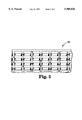
A wide variety of retroreflective sheeting designs are useful in conspicuity marking systems according to the present invention. The present invention contemplates the use of either beaded retroreflective sheetings or cube-corner type retroreflective sheetings. FIG. 3 is a schematic, cross-sectional view of one embodiment of cube-corner retroreflective sheeting 20 useful in conspicuity marking applications in accordance with the present invention. FIG. 4 is a plan view of the structured surface of the sheeting 20 depicted in FIG. 3. Referring to FIGS. 3 and 4, sheeting 20 comprises a substantially optically transparent substrate 22 having a base surface 24 and a structured surface 26 opposite base surface 24. Structured surface 26 comprises an array of cube corner elements 28. Each cube corner element 28 is in the shape of a trihedral prism having three substantially mutually perpendicular faces 30 which intersect at a point to define the apex 32 of the cube corner element 28. The cube corner elements 28 may be canted to improve the retroreflective performance of the sheeting as disclosed in U.S. Pat. No. 4,588,258, incorporated herein by reference. Additionally, the cube corner elements may be formed such that the faces 30 intersect at angles which deviate slightly from orthogonal angles, as disclosed in U.S. Pat. No. 4,775,219, incorporated herein by reference.
Retroreflective sheeting 20 may be of a single layer construction, wherein substrate 22 and cube corner elements 28 are composed of the same materials. Alternatively, retroreflective sheeting 20 may be of a multi-layer construction, wherein substrate 22 and cube corner elements 28 are composed of materials having different properties. According to one embodiment of the present invention, retroreflective sheeting 20 is manufactured in accordance with U.S. Pat. No. 5,450,235, incorporated herein by reference. In another embodiment, retroreflective sheeting 20 is manufactured in accordance with principles of the invention disclosed in U.S. Ser. No. 08/472,444, incorporated herein by reference. In brief summary, these disclosures are directed toward flexible, multi-layer retroreflective sheeting constructions wherein the substrate is formed from a relatively flexible material and the cube corner elements are formed from a relatively rigid material. These constructions provide a retroreflective sheeting which can be flexed or curved through a relatively small radius of curvature without causing significant distortion of the optical properties of the sheeting.
According to an embodiment disclosed in U.S. Pat. No. 5,450,235, a retroreflective sheeting for use in accordance with the present invention comprises a body layer which contains a light transmissible polymeric material having an elastic modulus less than 7×10⁸ pascals and a plurality of cube corner elements comprising a light transmissible polymeric material having an elastic modulus greater than 18×108 pascals. According to the embodiment disclosed in U.S. Ser. No. 08/472,444, retroreflective sheeting for use in accordance with the present invention comprises an overlay film comprising a flexible material and an array of cube corner elements formed from a relatively rigid material bonded to the overlay film. Preferably, the material composing the overlay film has an elastic modulus of less than about 13×108 pascals and the cube corner elements have and elastic modulus greater than about 25×108 pascals.
Illustrative examples of thermoplastic polymers that may be used in the cube-corner elements include acrylic polymers such as poly(methyl methacrylate); polycarbonates; cellulosics such as cellulose acetate, cellulose (acetate-co-butyrate), cellulose nitrate; epoxies; polyesters such as poly(butylene terephthalate), poly(ethylene terephthalate); fluoropolymers such as poly(chlorofluoroethylene), poly(vinylidene fluororide); polyamides such as poly(caprolactam), poly(amino caproic acid), poly(hexamethylene diamine-co-adipic acid), poly(amide-co-imide), and poly(ester-co-imide); polyetherketones; poly(etherimide); polyolefins such as poly(methylpentene); poly(phenylene ether); poly(phenylene sulfide); poly(styrene) and poly(styrene) copolymers such as poly(styrene-co-acrylonitrile), poly(styrene-co-acrylonitrile-co-butadiene); polysulfone; silicone modified polymers (i.e., polymers that contain a small weight percent (less than 10 weight percent) of silicone) such as silicone polyamide and silicone polycarbonate; fluorine modified polymers such as perfluoropoly(ethyleneterephthalate); and mixtures of the above polymers such as a poly(ester) and poly(carbonate) blend, and a fluoropolymer and acrylic polymer blend.
Additional materials suitable for forming the cube-corner elements are reactive resin systems capable of being crosslinked by a free radical polymerization mechanism by exposure to actinic radiation. for example, electron beam, ultraviolet light, or visible light. Additionally, these materials may be polymerized by thermal means with the addition of a thermal initiator such as benzoyl peroxide. Radiation-initiated cationically polymerizable resins also may be used.
Reactive resins suitable for forming the cube-corner elements may be blends of photoinitiator and at least one compound bearing an acrylate group. Preferably the resin blend contains a difunctional or polyfunctional compound to ensure formation of a crosslinked polymeric network upon irradiation.
Illustrative examples of resins that are capable of being polymerized by a free radical mechanism include acrylic-based resins derived from epoxies, polyesters, polyethers and urethanes, ethylenically unsaturated compounds, aminoplast derivatives having at least one pendant acrylate group, isocyanate derivatives having at least one pendant acrylate group, epoxy resins other than acrylated epoxies, and mixtures and combinations thereof The term acrylate is used here to encompass both acrylates and methacrylates. U.S. Pat. No. 4,576,850 to Martens (disclosure incorporated herein in its entirety by reference) discloses examples of crosslinked resins that may be used in the cube-corner elements of the present invention.
Ethylenically unsaturated resins include both monomeric and polymeric compounds that contain atoms of carbon, hydrogen and oxygen, and optionally nitrogen, sulfur and the halogens. Oxygen or nitrogen atoms or both are generally present in ether, ester, urethane, amide and urea groups. Ethylenically unsaturated compounds preferably have a molecular weight of less than about 4,000 and preferably are esters made from the reaction of compounds containing aliphatic monohydroxy groups or aliphatic polyhydroxy groups and unsaturated carboxylic acids, such as acrylic acid, methacrylic acid, itaconic acid, crotonic acid, isocrotonic acid, maleic acid, and the like.
Some examples of compounds having an acrylic or methacrylic group are listed below. The listed compounds are illustrative and not limiting.
(1) Monofunctional compounds:
ethylacrylate, n-butylacrylate, isobutylacrylate, 2-ethylhexylacrylate, n-hexylacrylate, n-octylacrylate, isobornyl acrylate, tetrahydrofurfuryl acrylate, 2-phenoxyethyl acrylate, and N,N-dimethylacrylamide;
(2) Difunctional compounds:
1,4-butanediol diacrylate, 1,6-hexanediol diacrylate, neopentylglycol diacrylate, ethylene glycol diacrylate, triethyleneglycol diacrylate, and tetraethylene glycol diacrylate;
(3) Polyfunctional compounds:
trimethylolpropane triacrylate, glyceroltriacrylate, pentaerythritol triacrylate, pentaerythritol tetraacrylate, and tris(2-acryloyloxyethyl)isocyanurate.
Some representative examples of other ethylenically unsaturated compounds and resins include styrene, divinylbenzene, vinyl toluene, N-vinyl pyrrolidone, N-vinyl caprolactam, monoallyl, polyallyl, and polymethallyl esters such as diallyl phthalate and diallyl adipate, and amides of carboxylic acids such as and N,N-diallyladipamide.
Illustrative examples of photopolymerization initiators which can be blended with the acrylic compounds include the following: benzil, methyl o-benzoate, benzoin, benzoin ethyl ether, benzoin isopropyl ether, benzoin isobutyl ether, etc., benzophenone/tertiary amine, acetophenones such as 2,2-diethoxyacetophenone, benzil methyl ketal, 1-hydroxycyclohexyl phenyl ketone, 2-hydroxy-2-methyl-1-phenylpropan-1-one, 1-(4-isopropylphenyl)-2-hydroxy-2-methylpropan-1-one, 2-benzyl-2-N,N-dimethylamino-1-(4-morpholinophenyl)-1-butanone, 2,4,6-trimethylbenzoyldiphenylphosphine oxide, 2-methyl-1-4-(methylthio)phenyl-2-morpholino-1-propanone, et cetera. These compounds may be used individually or in combination.
Cationically polymerizable materials include but are not limited to materials containing epoxy and vinyl ethers functional groups. These systems are photoinitiated by onium salt initiators such as triarylsulfonium, and diaryliodonium salts.
Preferred polymers for the cube-corner elements include poly(carbonate), poly(methylmethacrylate), poly(ethyleneterephthalate), and crosslinked acrylates such as multi-functional acrylates or epoxies and acrylated urethanes blended with mono- and multi-functional monomers. These polymers are preferred for one or more of the following reasons: thermal stability, environmental stability, clarity, excellent release from the tooling or mold, and capable of receiving a reflective coating.
Illustrative examples of polymers that may be employed in the body layer include:
fluorinated polymers such as: poly(chlorotrifluoroethylene), for example Kel-F800™ available from 3M St. Paul, Minn.; poly(tetrafluoroethylene-co-hexafluoropropylene), for example Exac FEP™ available from Norton Performance, Brampton, Mass.; poly(tetrafluoroethylene-co-perfluoro(alkyl)vinylether), for example, Exac PEA™ also available from Norton Performance; and poly(vinylidene fluoride-co-hexafluoropropylene), for example, Kynar Flex-2800™ available from Pennwalt Corporation, Philadelphia, Pa.;
ionomeric ethylene copolymers such as: poly(ethylene-co-methacrylic acid) with sodium or zinc ions such as Surlyn-8920™ and Surlyn-9910™ available from E. I. duPont Nemours, Wilmington, Del.;
low density polyethylenes such as: low density polyethylene; linear low density polyethylene; and very low density polyethylene;
plasticized vinyl halide polymers such as plasticized poly(vinylchloride);
polyethylene copolymers including: acid functional polymers such as poly(ethylene-co-acrylic acid) and poly(ethylene-co-methacrylic acid) poly(ethylene-co-maleic acid), and poly(ethylene-co-fumaric acid); acrylic functional polymers such as poly(ethylene-co-alkylacrylates) where the alkyl group is methyl, ethyl, propyl, butyl, et cetera, or CH3 (CH2)n -- where n is 0-12, and poly(ethylene-co-vinylacetate); and
aliphatic and aromatic polyurethanes derived from the following monomers (1)-(3): (1) diisocyanates such as dicyclohexylmethane-4,4'-diisocyanate, isophorone diisocyanate, 1,6-hexamethylene diisocyanate, cyclohexyl diisocyanate, diphenylmethane diisocyanate, and combinations of these diisocyanates, (2) polydiols such as polypentyleneadipate glycol, polytetramethylene ether glycol, polyethylene glycol, polycaprolactone diol, poly-1,2-butylene oxide glycol, and combinations of these polydiols, and (3) chain extenders such as butanediol or hexanediol. Commercially available urethane polymers include: PN-03, or 3429 from Morton International Inc., Seabrook, N.H.
Combinations of the above polymers also may be employed in the body layer of the body portion. Preferred polymers for the body layer include: the ethylene copolymers that contain units that contain carboxyl groups or esters of carboxylic acids such as poly(ethylene-co-acrylic acid), poly(ethylene-co-methacrylic acid), poly(ethylene-co-vinylacetate); the ionomeric ethylene copolymers; plasticized poly(vinylchloride); and the aliphatic urethanes. These polymers are preferred for one or more of the following reasons: suitable mechanical properties, good adhesion to the land layer, clarity, and environmental stability.
A seal film can be applied to the backside of the cube-corner elements; see, for example, U.S. Pat. Nos. 4,025,159 and 5,117,304. The sealing film maintains an air interface at the backside of the cubes to provide retroreflectivity according to the principles of total internal reflection. Alternatively, a specular reflective coating such as a metallic coating (not shown) can be placed on the backside of the cube-corner elements 28 to promote retroreflection by specular reflection. Metallic coatings also prevent light leakage from the retroreflective sheeting. The metallic coating can be applied by known techniques such as vapor depositing or chemically depositing a metal such as aluminum, silver, or nickel. A primer layer may be applied to the backside of the cube-corner elements to promote the adherence of the metallic coating. A backing and/or an adhesive layer also can be disposed behind the cube-corner elements to enable the cube-corner retroreflective sheeting 20 to be secured to a substrate.
Another aspect of the present invention relates to the ability to design a conspicuity marking system for particular viewing and lighting geometries. The optical profile of light retroreflected from retroreflective sheeting is a function of the geometry of the retroreflective elements on the sheeting. A wide variety of cube corner sheeting optics are presently commercially available. By selecting a retroreflective sheeting having the appropriate retroreflective element geometry, the system may be tailored to exhibit its optimal performance at predetermined illumination and viewing angles.
For example, FIG. 5 is a plan view of the structured surface of a second embodiment of a cube corner retroreflective sheeting 40 which may be used in conspicuity marking systems according to the present invention. Retroreflective sheeting 40 is designed to retroreflect light incident on sheeting 40 at high entrance angles relative to an axis extending normally from the plane of the sheeting. See U.S. Pat. No. 4,938,563, incorporated herein by reference. A conspicuity marking system which incorporates retroreflective sheeting in accordance with FIG. 5 is particularly well adapted for use in conspicuity marking applications which are characterized by high incidence angle lighting conditions. Examples include: jersey barrier marking applications, pavement marking applications. An important advantage of the present invention is the ability to select a retroreflective sheeting design according to the particular requirements of an application.
In yet another embodiment of a conspicuity marking system according to the present invention a retroreflective surface may be formed into a portion of the reflective surface of the light guide. For example, in the system depicted in FIGS. 1-2, a retroreflective surface may be formed into a portion of optical fiber core 14.
FIG. 6 is a schematic plan view of a highway traffic sign 60 which incorporates a conspicuity marking system 10 in accordance with aspects of the present invention. Referring to FIG. 6 a conspicuity marking system 10 in accordance with the present invention may extend substantially entirely around the perimeter of the sign 60. Light source 62 injects light into optical fiber 12 to provide active illumination of the stop sign. Advantageously, conspicuity marking system 10 will retroreflect light incident on sign 60 from an external light source such as, for example, automobile headlights. Light source 62 is preferably capable of injecting light into optical fiber 12 in a cone which is less than the acceptance angle of the optical fiber. The acceptance angle of a light guide is a function of the difference in refractive indices of the optical fiber core 14 and the cladding 16, if any. Commercially available light sources suitable for injecting light into large diameter optical fibers include quartz-halogen lamps, metal halide lamps, and xenon-metal halide lamps.
Another aspect of the present invention is the ability to provide conspicuity marking along a length or following a contour of an article. For example, a conspicuity marking system in accordance with the present invention may be positioned along the entire length of a vehicle such as, for example, an automobile, a school bus or a semi-truck trailer, boats, boat trailers, etc. Alternatively, a conspicuity marking system may extend around the full contour of the side or rear wall of a vehicle or around the perimeter of a road sign or traffic cone. Additionally, retro-fitting a vehicle with a conspicuity system in accordance with the present invention requires relatively minimal expense and relatively little physical alteration of the vehicle.
FIG. 7 is a perspective view of a highway vehicle 70 which incorporates a conspicuity marking system 10 in accordance with aspects of the present invention. Because both the optical fiber and the retroreflective sheeting are relatively flexible, the fiber may extend around the full contour of the surface of the vehicle. Optical fiber 12 may be formed from a substantially transparent material or, if desired, may include colorants, pigments, or dyes to change the color of the system. Additionally, optical fiber 12 may be supplied with white light or with colored light to change the color of the system.
As discussed briefly above, another aspect of the present invention is the ability to incorporate a wide variety of configurations of light guides. FIG. 8 depicts an embodiment of a conspicuity marking system 80 in accordance with the present invention in which one surface of a substantially rectangular light guide 82 is optically coupled with retroreflective sheeting 84. Optical fiber 82 is shown without a cladding layer surrounding fiber 82, however it will be appreciated that optical fiber 82 could include a cladding layer in accordance with the discussion pertaining to FIGS. 1-2 above. Retroreflective sheeting 84 comprises a single layer substrate 86 which comprises a base surface 87 and structured surface including an array of cube corner elements 88 opposite base surface 88. Additionally, a seal film 90 is connected to the structured surface to provide an air interface such that cube corner elements reflect light according to the principles of total internal reflection. Conspicuity marking system 80 functions according to the same principles discussed in conjunction with FIGS. 1-2.
The above discussion discloses a conspicuity marking system which comprises at least one optically reflective surface and retroreflective light extraction means optically coupled with a portion of the surface. Although multiple embodiments of the present invention has been illustrated and described, it will be appreciated by those of ordinary skill in the art that insubstantial changes calculated to achieve the same result may be substituted for the specific embodiments and steps disclosed above. This application is intended to cover any such adaptations or variations of the present invention. Therefore, it is intended that this invention be limited only by the appended claims and equivalents thereof.
EXAMPLES Cube Corner Retroreflective Sheeting
A conspicuity marking system in accordance with the present invention was constructed at the 3M Center in St. Paul, Minn., U.S.A. A 6 mil polyurethane film (commerically available as 3M Scotch™ brand polyurethane protective tape) was laminated to a polyester siliconized release liner. This film was used as an overlay film to which an array of cube corner elements could be cured. A resin blend of 25 percent by weight trishydroxyethyl isocyanurate triacrylate, 50 percent by weight trimethylolpropane triacrylate, and 25 percent by weight tetrahydrofurfuryl acrylate containing 6.62×10⁻² mol/kg of photoinitiator CGI-1700, commercially available from Ciba-Geigy Corporation, was coated into the cavities of a cube corner mold having a cube corner geometry as disclosed in U.S. Pat. No. 4,588,258. The polyurethane surface of the adhesive laminate was then laminated onto the resin, using an ink roller to minimize the resin thickness. The sheeting was cured using high intensity UV-visible light from a Fusion-EPIQ 6000 "V" lamp (operating at 600 W/in). The replicated laminate was stepped from the tool and annealed in an oven at 200 degrees Fahrenheit for five minutes.
A one inch section of cladding was removed from a 13.5" (343 millimeter) length of 3/8" (9.5 millimeter) diameter optical fiber, exposing the optical fiber core. The fiber used is commercially available as Lumenyte Optical Fiber EL-400 from Lumenyte International Corporation in Costa Mesa, Calif., U.S.A. A 1/4"×2" (6.35 millimeter×50.8 millimeter) piece of the retroreflective sheeting discussed above was adhered to the surface of the optical fiber core such that the base surface of the sheeting was optically coupled with the surface of the optical fiber core.
Light was injected into one end of the optical fiber using a tungsten-halogen light source equipped with a fiber optic light guide. The opposing end of the fiber was covered with a reflective coating. The optical fiber emitted light from its surface in a region approximately opposite the location of the retroreflective sheeting. To test the retroreflective capabilities of the sheeting a light source was directed through the optical fiber toward the retroreflective sheeting. The incident light was effectively retroreflected toward the light source.
Beaded Retroreflective Sheeting
A conspicuity marking system in accordance with the present invention was constructed at the 3M Center in St. Paul, Minn., U.S.A. A one inch section of cladding was removed from a 13.5" (343 millimeter) length of 3/8" (9.5 millimeter) diameter optical fiber, exposing the optical fiber core. The fiber used is commercially available as Lumenyte Optical Fiber EL-400 from Lumenyte Corporation in Costa Mesa, Calif., U.S.A. A 6"×6" (152.4×152.4 mm) sheet of 3M VHB Adhesive (F9460PC) was laminated onto the front surface of a 7"×7" (177.8 mm×177.8 mm) sheet of 3M Reflecto-Lite retroreflective sheeting. A 1/4"×1" piece was cut from the the retroreflective sheeting laminate and adhered to the surface of the optical fiber core.
Light was injected into one end of the optical fiber using tungsten-halogen light source equipped with a fiber optic light guide. The opposing end of the fiber was covered with a reflective coating. The retroreflective laminate extracted light from the fiber in a region approximately opposite the fiber from the sheeting. The light source was removed from the fiber and a separate light source was directed at the through the fiber from a position approximately opposite the retroreflective laminate. The retroreflective laminate effectively retroreflected the light toward the light source.

Claims (16)

What is claimed is:
1. A conspicuity marking system, comprising:
a light guide having at least one optically reflective surface for propagating light through the light guide; and
retroreflective light extraction means optically coupled with a portion of the optically reflective surface of the light guide for (1) reflecting a portion of the light propagating axially through the light guide such that the light is transmitted from a surface of the light guide at a location displaced from the retroreflective light extraction means, and (2) retroreflecting light from an external light source which is incident on the light guide.
2. A conspicuity marking system according to claim 1, wherein:
the light guide comprises an optical fiber having a length extending along a longitudinal axis of the fiber.
3. A conspicuity marking system according to claim 1, wherein the optical fiber includes:
an optical fiber core measuring between at least about 3.0 millimeters in diameter and comprising a substantially optically transparent material; and
a cladding layer surrounding the optical fiber core, the cladding formed from a material having a refractive index less than the refractive index of the optical core such that light injected into one end of the optical fiber propagates through the fiber according to the principles of total internal reflection.
4. A conspicuity marking system according to claim 3, wherein:
the optical fiber core comprises a material having a refractive index of between 1.46 and 1.6; and
the cladding layer is formed from a material having a refractive index of between 1.35 and 1.42.
5. A conspicuity marking system according to claim 3, wherein:
the optical fiber core contains a polymer selected from the group consisting of polymethylmethacrylate and polycarbonate.
6. A conspicuity marking system according to claim 2, wherein:
the optical fiber has a cross-sectional shape selected from the group consisting of circular, elliptical, and polygonal.
7. A conspicuity marking system according to claim 2, wherein:
the light guide comprises a planar wave guide.
8. A conspicuity marking system according to claim 1, wherein:
the retroreflective light extraction means comprise a microstructured retroreflective surface formed in the optically reflective surface.
9. A conspicuity marking system according to claim 1, wherein:
the retroreflective light extraction means comprise a thin, flexible strip of beaded retroreflective sheeting.
10. A conspicuity marking system according to claim 1, wherein:
the retroreflective light extraction means comprise a thin, flexible strip of cube-corner retroreflective sheeting.
11. A conspicuity marking system according to claim 10, wherein the cube-corner retroreflective sheeting comprises:
a body layer comprising a first material having an elastic modulus less than 7×10⁸ pascals; and
a plurality of cube corner elements comprising a second material having an elastic modulus greater than about 18×108 pascals.
12. A conspicuity marking system according to claim 10, wherein the cube-corner retroreflective sheeting comprises:
a body layer comprising a first material having an elastic modulus less than 13×108 pascals; and
a plurality of cube corner elements comprising a second material having an elastic modulus greater than about 25×108 pascals.
13. A conspicuity marking system, comprising:
a light guide having at least one optically reflective surface for propagating light along the light guide; and
retroreflective sheeting optically coupled with a portion of the optically reflective surface of the light guide.
14. A conspicuity marking system according to claim 13, wherein the retroreflective sheeting comprises a retroreflective structured surface.
15. A conspicuity marking system according to claim 13, wherein the retroreflective sheeting comprises a plurality of retroreflective beads.
16. A conspicuity marking system, comprising:
a light guide having at least one optically reflective surface for propagating light along the light guide, wherein at least portion of the optically reflective surface includes an array of retroreflective cube corner elements formed therein.
US08/590,746 1996-01-24 1996-01-24 Conspicuity marking system including light guide and retroreflective structure Expired - Lifetime US5905826A (en)

Priority Applications (9)

Application Number Priority Date Filing Date Title
US08/590,746 US5905826A (en) 1996-01-24 1996-01-24 Conspicuity marking system including light guide and retroreflective structure
PCT/US1996/020535 WO1997027423A1 (en) 1996-01-24 1996-12-17 Conspicuity marking system
AU14301/97A AU1430197A (en) 1996-01-24 1996-12-17 Conspicuity marking system
CN96180139A CN1209195A (en) 1996-01-24 1996-12-17 Conspicuity marking system
JP9526844A JP2000505167A (en) 1996-01-24 1996-12-17 Significant signage system
CA002242233A CA2242233A1 (en) 1996-01-24 1996-12-17 Conspicuity marking system
KR1019980705599A KR19990081887A (en) 1996-01-24 1996-12-17 Prominence display system
DE69628766T DE69628766T2 (en) 1996-01-24 1996-12-17 EASILY DETECTABLE MARKING SYSTEM
EP96944524A EP0876566B1 (en) 1996-01-24 1996-12-17 Conspicuity marking system

Applications Claiming Priority (1)

Application Number Priority Date Filing Date Title
US08/590,746 US5905826A (en) 1996-01-24 1996-01-24 Conspicuity marking system including light guide and retroreflective structure

Publications (1)

Publication Number Publication Date
US5905826A true US5905826A (en) 1999-05-18

Family

ID=24363531

Family Applications (1)

Application Number Title Priority Date Filing Date
US08/590,746 Expired - Lifetime US5905826A (en) 1996-01-24 1996-01-24 Conspicuity marking system including light guide and retroreflective structure

Country Status (9)

Country Link
US (1) US5905826A (en)
EP (1) EP0876566B1 (en)
JP (1) JP2000505167A (en)
KR (1) KR19990081887A (en)
CN (1) CN1209195A (en)
AU (1) AU1430197A (en)
CA (1) CA2242233A1 (en)
DE (1) DE69628766T2 (en)
WO (1) WO1997027423A1 (en)

Cited By (43)

* Cited by examiner, † Cited by third party
Publication number Priority date Publication date Assignee Title
US6039553A (en) * 1998-12-02 2000-03-21 3M Innovative Properties Company Apparatus for molding light extraction structures onto a light guide
US6195016B1 (en) * 1999-08-27 2001-02-27 Advance Display Technologies, Inc. Fiber optic display system with enhanced light efficiency
US6253477B1 (en) * 1998-09-23 2001-07-03 Hallmark Technologies, Inc. Retro-reflective sign
EP1127984A1 (en) * 1999-08-30 2001-08-29 Matsushita Shokai Co., LTD. Planar light emitting device and light-emitting guide
US20020075545A1 (en) * 1998-12-22 2002-06-20 Harrison Daniel David Optcal high speed communications for a computed tomography x-ray machine
US6425342B1 (en) * 1997-10-23 2002-07-30 Dale E. Hohman Method of cautionary warning on vessels and a removable cautionary warning device
US6431717B1 (en) 2000-03-07 2002-08-13 Federal-Mogul World Wide, Inc. Keyed waveguide assembly and method for making same
US6470114B1 (en) * 1999-08-23 2002-10-22 Infineon Technologies Ag Retroreflective conductors for optical fiber interconnects
US6535667B1 (en) 2001-12-31 2003-03-18 3M Innovative Properties Company Light fiber comprising continuous outer cladding and method of making
US20030128956A1 (en) * 2002-01-08 2003-07-10 Photon-X, Inc. Optical polymer blends with adjustable refractive index and optical waveguides using same
US20030156426A1 (en) * 2000-08-07 2003-08-21 Marcello Givoletti Textile product with illuminated fibres, article made therefrom and production method of the same
US20030156431A1 (en) * 2001-12-31 2003-08-21 Gozum John E. Illumination device
WO2003098276A2 (en) * 2002-05-15 2003-11-27 Reflexite Corporation Retroreflective sheeting with air-backed microstructures
US20040033048A1 (en) * 2002-08-15 2004-02-19 Visteon Global Technologies,Inc. Light channel communication system
US20040169928A1 (en) * 2002-05-15 2004-09-02 Reflexite Corporation Optical structures
US20040208463A1 (en) * 2003-04-15 2004-10-21 Kyung-Tae Park Cable for use in an air blowing installation and apparatus for manufacturing the same
US6825987B2 (en) * 2002-07-17 2004-11-30 C.R.F. Societa Consortile Per Azioni Light guide for display devices of the head-mounted or head-up type
US20060138694A1 (en) * 2004-12-23 2006-06-29 Biernath Rolf W Method of making a polymeric film having structured surfaces via replication
US20060138686A1 (en) * 2004-12-23 2006-06-29 Ouderkirk Andrew J Method of making a uniaxially stretched polymeric film having structured surface
US20060141218A1 (en) * 2004-12-23 2006-06-29 Biernath Rolf W Uniaxially oriented articles having structured surface
US20060138705A1 (en) * 2004-12-23 2006-06-29 Korba Gary A Method of making a structured surface article
US20060138702A1 (en) * 2004-12-23 2006-06-29 Biernath Rolf W Method of making uniaxially oriented articles having structured surfaces
US20060141219A1 (en) * 2004-12-23 2006-06-29 Benson Olester Jr Roll of a uniaxially oriented article having a structured surface
US20060141220A1 (en) * 2004-12-23 2006-06-29 Merrill William W Uniaxially oriented article having a structured surface
US20060204720A1 (en) * 2004-12-23 2006-09-14 Biernath Rolf W Uniaxially oriented birefringent article having a structured surface
US20070031140A1 (en) * 2005-08-04 2007-02-08 Biernath Rolf W Article having a birefringent surface and microstructured features having a variable pitch or angles for use as a blur filter
WO2007149890A2 (en) * 2006-06-22 2007-12-27 3M Innovative Properties Company Birefringent structured film for led color mixing in a backlight
US20080014410A1 (en) * 2006-06-28 2008-01-17 3M Innovative Properties Company Oriented Polymeric Articles and Method
US20080053800A1 (en) * 2006-08-30 2008-03-06 3M Innovative Properties Company Keypad light guide
US20090064993A1 (en) * 2007-09-10 2009-03-12 Banyan Energy, Inc. Solar energy concentrator
US20090067784A1 (en) * 2007-09-10 2009-03-12 Banyan Energy, Inc. Compact optics for concentration, aggregation and illumination of light energy
US20090173654A1 (en) * 2008-01-04 2009-07-09 Nanoventions Holdings, Llc Merchandising Systems, Methods of Merchandising, and Point-Of-Sale Devices Comprising Micro-Optics Technology
WO2010005810A2 (en) * 2008-07-10 2010-01-14 3M Innovative Properties Company Retroreflective articles and devices having viscoelastic lightguide
US20110122494A1 (en) * 2008-07-10 2011-05-26 Sherman Audrey A Retroreflective articles and devices having viscoelastic lightguide
US20110148661A1 (en) * 2008-07-02 2011-06-23 Shinichi Shikii Guiding device
US20110293219A1 (en) * 2010-05-28 2011-12-01 Gary Weiner Chiral Fiber System and Method for Providing Configurable Light Extraction from Optical Waveguides in Accordance with at Least One Predetermined Light Extraction Profile
US8412010B2 (en) 2007-09-10 2013-04-02 Banyan Energy, Inc. Compact optics for concentration and illumination systems
US8705914B2 (en) 2007-09-10 2014-04-22 Banyan Energy, Inc. Redirecting optics for concentration and illumination systems
US9285531B2 (en) 2008-08-08 2016-03-15 3M Innovative Properties Company Lightguide having a viscoelastic layer for managing light
US9308051B2 (en) 2011-11-15 2016-04-12 Smiths Medical Asd, Inc. Illuminated tubing set
US9308323B2 (en) 2011-11-15 2016-04-12 Smiths Medical Asd, Inc. Systems and methods for illuminated medical tubing detection and management indicating a characteristic of at least one infusion pump
US20180186282A1 (en) * 2016-12-30 2018-07-05 Valeo North America, Inc. Integration of side reflex and light pipe side marker
US10228507B2 (en) 2008-07-10 2019-03-12 3M Innovative Properties Company Light source and optical article including viscoelastic lightguide disposed on a substrate

Families Citing this family (3)

* Cited by examiner, † Cited by third party
Publication number Priority date Publication date Assignee Title
US5995690A (en) * 1996-11-21 1999-11-30 Minnesota Mining And Manufacturing Company Front light extraction film for light guiding systems and method of manufacture
DE102009059797A1 (en) 2009-12-21 2011-06-22 Krauss-Maffei Wegmann GmbH & Co. KG, 80997 Optical marker and object detection device
CN114484377A (en) * 2022-03-04 2022-05-13 浙江极氪智能科技有限公司 Illumination structure, car lamp and vehicle utilizing retro-reflector to emit light

Citations (50)

* Cited by examiner, † Cited by third party
Publication number Priority date Publication date Assignee Title
US4025159A (en) * 1976-02-17 1977-05-24 Minnesota Mining And Manufacturing Company Cellular retroreflective sheeting
US4059916A (en) * 1975-01-30 1977-11-29 Copal Company Limited Light diffusing device
JPS5329740A (en) * 1976-08-31 1978-03-20 Nippon Telegr & Teleph Corp <Ntt> Light branch and connecting circuit by use of optical fiber
US4171844A (en) * 1977-06-30 1979-10-23 Landaal Calvin L Tailgate shaft and loading ramp for pick-up trucks
US4173390A (en) * 1976-03-16 1979-11-06 Patelhold Patentverwertungs- & Electro-Holding Ag Fiber optic T-coupler
US4234907A (en) * 1979-01-29 1980-11-18 Maurice Daniel Light emitting fabric
US4285889A (en) * 1979-12-26 1981-08-25 Hughes Aircraft Company Method for fabricating thin panel illuminator
US4307932A (en) * 1977-09-30 1981-12-29 Siemens Aktiengesellschaft Arrangement for detecting a branched off signal
US4422719A (en) * 1981-05-07 1983-12-27 Space-Lyte International, Inc. Optical distribution system including light guide
US4447118A (en) * 1981-09-21 1984-05-08 The Boeing Company Optical information transfer system
US4460940A (en) * 1981-11-07 1984-07-17 Kei Mori Apparatus for uniform illumination employing light diffuser
US4466697A (en) * 1981-11-12 1984-08-21 Maurice Daniel Light dispersive optical lightpipes and method of making the same
US4471412A (en) * 1982-01-09 1984-09-11 Kei Mori Illumination device
US4519017A (en) * 1982-09-29 1985-05-21 Maurice Daniel Light emitting optical fiber assemblies and method for forming the same
US4576436A (en) * 1983-01-31 1986-03-18 Maurice Daniel Light distribution and collection assemblies and methods
US4576850A (en) * 1978-07-20 1986-03-18 Minnesota Mining And Manufacturing Company Shaped plastic articles having replicated microstructure surfaces
US4588258A (en) * 1983-09-12 1986-05-13 Minnesota Mining And Manufacturing Company Cube-corner retroreflective articles having wide angularity in multiple viewing planes
JPS629206A (en) * 1985-07-06 1987-01-17 Fujiyama Giken:Kk Seal width measuring instrument for continuous seal machine
JPS629205A (en) * 1985-07-05 1987-01-17 Mita Ind Co Ltd Original size detecting device
US4642736A (en) * 1984-07-02 1987-02-10 Mitsubishi Rayon Company, Ltd. Light diffuser
US4648690A (en) * 1984-08-27 1987-03-10 Mitsubishi Rayon Company, Ltd. Light diffusing device
US4690490A (en) * 1983-09-27 1987-09-01 Kei Mori Light diverting device
US4729068A (en) * 1986-10-01 1988-03-01 Mitsubishi Rayon Company Ltd. Light diffusing device
US4743410A (en) * 1985-03-29 1988-05-10 Siemens Aktiengesellschaft Method for manufacturing a flat illumination unit
JPS63121002A (en) * 1986-11-08 1988-05-25 Hiromasa Kitaguchi Optical fiber capable of emitting light in transverse direction
US4775219A (en) * 1986-11-21 1988-10-04 Minnesota Mining & Manufacturing Company Cube-corner retroreflective articles having tailored divergence profiles
US4822123A (en) * 1981-07-13 1989-04-18 Kei Mori Optical radiator
US4845596A (en) * 1987-07-29 1989-07-04 E. I. Du Pont De Nemours And Company Surface illumination device using optical conductors
DE3801385A1 (en) * 1988-01-19 1989-07-27 Aristo Graphic Systeme Photographic drawing-head arrangement
FR2626381A1 (en) * 1988-01-21 1989-07-28 Solvay OPTICAL GUIDE OF LIGHT
US4865417A (en) * 1986-06-18 1989-09-12 Mitsubishi Rayon Co., Ltd. Optical fiber device
US4885663A (en) * 1988-03-22 1989-12-05 Lumitex, Inc. Fiber optic light emitting panel and method of making same
US4907132A (en) * 1988-03-22 1990-03-06 Lumitex, Inc. Light emitting panel assemblies and method of making same
US4929169A (en) * 1987-06-19 1990-05-29 Mitsubishi Rayon Co. Working equipment for roughening the side of optical fiber
US4938563A (en) * 1986-11-21 1990-07-03 Minnesota Mining And Manufacturing Company High efficiency cube corner retroflective material
US5005931A (en) * 1989-03-13 1991-04-09 Kei Mori Light radiator
US5009020A (en) * 1987-11-25 1991-04-23 Sakae Riken Kogyo Co., Ltd. Light-passing decorative object
US5027259A (en) * 1990-03-05 1991-06-25 Chujko Daniel A Flexible light pipe with improved performance coating
US5037172A (en) * 1989-03-22 1991-08-06 Teledyne Industry, Inc. Fiber optic device with a reflective notch coupler
US5050946A (en) * 1990-09-27 1991-09-24 Compaq Computer Corporation Faceted light pipe
US5117304A (en) * 1990-09-21 1992-05-26 Minnesota Mining And Manufacturing Company Retroreflective article
US5122939A (en) * 1991-06-07 1992-06-16 David Kazdan Safety lighting and reflector system
US5187765A (en) * 1991-07-23 1993-02-16 Fostec, Inc. Backlighted panel
US5226105A (en) * 1991-06-27 1993-07-06 Poly-Optical Products, Inc. Fiber optic backlighting panel and dot process for making same
US5298327A (en) * 1986-07-08 1994-03-29 Lumenyte International Corporation High temperature plastic light conduit and composition of matter therefor
WO1994020871A1 (en) * 1993-03-11 1994-09-15 Nioptics Corporation Tapered multilayer luminaire devices
US5432876A (en) * 1992-10-19 1995-07-11 Minnesota Mining And Manufacturing Company Illumination devices and optical fibres for use therein
US5450235A (en) * 1993-10-20 1995-09-12 Minnesota Mining And Manufacturing Company Flexible cube-corner retroreflective sheeting
DE4419544A1 (en) * 1994-06-03 1995-12-07 Wolfgang Dammert Warning device for alerting to danger in accident black spots, building sites, etc.
US5506929A (en) * 1994-10-19 1996-04-09 Clio Technologies, Inc. Light expanding system for producing a linear or planar light beam from a point-like light source

Patent Citations (51)

* Cited by examiner, † Cited by third party
Publication number Priority date Publication date Assignee Title
US4059916A (en) * 1975-01-30 1977-11-29 Copal Company Limited Light diffusing device
US4025159A (en) * 1976-02-17 1977-05-24 Minnesota Mining And Manufacturing Company Cellular retroreflective sheeting
US4173390A (en) * 1976-03-16 1979-11-06 Patelhold Patentverwertungs- & Electro-Holding Ag Fiber optic T-coupler
JPS5329740A (en) * 1976-08-31 1978-03-20 Nippon Telegr & Teleph Corp <Ntt> Light branch and connecting circuit by use of optical fiber
US4171844A (en) * 1977-06-30 1979-10-23 Landaal Calvin L Tailgate shaft and loading ramp for pick-up trucks
US4307932A (en) * 1977-09-30 1981-12-29 Siemens Aktiengesellschaft Arrangement for detecting a branched off signal
US4576850A (en) * 1978-07-20 1986-03-18 Minnesota Mining And Manufacturing Company Shaped plastic articles having replicated microstructure surfaces
US4234907A (en) * 1979-01-29 1980-11-18 Maurice Daniel Light emitting fabric
US4285889A (en) * 1979-12-26 1981-08-25 Hughes Aircraft Company Method for fabricating thin panel illuminator
US4422719A (en) * 1981-05-07 1983-12-27 Space-Lyte International, Inc. Optical distribution system including light guide
US4822123A (en) * 1981-07-13 1989-04-18 Kei Mori Optical radiator
US4447118A (en) * 1981-09-21 1984-05-08 The Boeing Company Optical information transfer system
US4460940A (en) * 1981-11-07 1984-07-17 Kei Mori Apparatus for uniform illumination employing light diffuser
US4466697A (en) * 1981-11-12 1984-08-21 Maurice Daniel Light dispersive optical lightpipes and method of making the same
US4471412A (en) * 1982-01-09 1984-09-11 Kei Mori Illumination device
US4519017A (en) * 1982-09-29 1985-05-21 Maurice Daniel Light emitting optical fiber assemblies and method for forming the same
US4576436A (en) * 1983-01-31 1986-03-18 Maurice Daniel Light distribution and collection assemblies and methods
US4588258A (en) * 1983-09-12 1986-05-13 Minnesota Mining And Manufacturing Company Cube-corner retroreflective articles having wide angularity in multiple viewing planes
US4690490A (en) * 1983-09-27 1987-09-01 Kei Mori Light diverting device
US4642736A (en) * 1984-07-02 1987-02-10 Mitsubishi Rayon Company, Ltd. Light diffuser
US4648690A (en) * 1984-08-27 1987-03-10 Mitsubishi Rayon Company, Ltd. Light diffusing device
US4743410A (en) * 1985-03-29 1988-05-10 Siemens Aktiengesellschaft Method for manufacturing a flat illumination unit
JPS629205A (en) * 1985-07-05 1987-01-17 Mita Ind Co Ltd Original size detecting device
JPS629206A (en) * 1985-07-06 1987-01-17 Fujiyama Giken:Kk Seal width measuring instrument for continuous seal machine
US4865417A (en) * 1986-06-18 1989-09-12 Mitsubishi Rayon Co., Ltd. Optical fiber device
US5298327A (en) * 1986-07-08 1994-03-29 Lumenyte International Corporation High temperature plastic light conduit and composition of matter therefor
US4729068A (en) * 1986-10-01 1988-03-01 Mitsubishi Rayon Company Ltd. Light diffusing device
JPS63121002A (en) * 1986-11-08 1988-05-25 Hiromasa Kitaguchi Optical fiber capable of emitting light in transverse direction
US4938563A (en) * 1986-11-21 1990-07-03 Minnesota Mining And Manufacturing Company High efficiency cube corner retroflective material
US4775219A (en) * 1986-11-21 1988-10-04 Minnesota Mining & Manufacturing Company Cube-corner retroreflective articles having tailored divergence profiles
US4929169A (en) * 1987-06-19 1990-05-29 Mitsubishi Rayon Co. Working equipment for roughening the side of optical fiber
US4845596A (en) * 1987-07-29 1989-07-04 E. I. Du Pont De Nemours And Company Surface illumination device using optical conductors
US5009020A (en) * 1987-11-25 1991-04-23 Sakae Riken Kogyo Co., Ltd. Light-passing decorative object
DE3801385A1 (en) * 1988-01-19 1989-07-27 Aristo Graphic Systeme Photographic drawing-head arrangement
FR2626381A1 (en) * 1988-01-21 1989-07-28 Solvay OPTICAL GUIDE OF LIGHT
US4885663A (en) * 1988-03-22 1989-12-05 Lumitex, Inc. Fiber optic light emitting panel and method of making same
US4907132A (en) * 1988-03-22 1990-03-06 Lumitex, Inc. Light emitting panel assemblies and method of making same
US5005931A (en) * 1989-03-13 1991-04-09 Kei Mori Light radiator
US5037172A (en) * 1989-03-22 1991-08-06 Teledyne Industry, Inc. Fiber optic device with a reflective notch coupler
US5027259A (en) * 1990-03-05 1991-06-25 Chujko Daniel A Flexible light pipe with improved performance coating
US5117304A (en) * 1990-09-21 1992-05-26 Minnesota Mining And Manufacturing Company Retroreflective article
US5050946A (en) * 1990-09-27 1991-09-24 Compaq Computer Corporation Faceted light pipe
US5122939A (en) * 1991-06-07 1992-06-16 David Kazdan Safety lighting and reflector system
US5226105A (en) * 1991-06-27 1993-07-06 Poly-Optical Products, Inc. Fiber optic backlighting panel and dot process for making same
US5187765A (en) * 1991-07-23 1993-02-16 Fostec, Inc. Backlighted panel
US5432876A (en) * 1992-10-19 1995-07-11 Minnesota Mining And Manufacturing Company Illumination devices and optical fibres for use therein
US5432876C1 (en) * 1992-10-19 2002-05-21 Minnesota Mining & Mfg Illumination devices and optical fibres for use therein
WO1994020871A1 (en) * 1993-03-11 1994-09-15 Nioptics Corporation Tapered multilayer luminaire devices
US5450235A (en) * 1993-10-20 1995-09-12 Minnesota Mining And Manufacturing Company Flexible cube-corner retroreflective sheeting
DE4419544A1 (en) * 1994-06-03 1995-12-07 Wolfgang Dammert Warning device for alerting to danger in accident black spots, building sites, etc.
US5506929A (en) * 1994-10-19 1996-04-09 Clio Technologies, Inc. Light expanding system for producing a linear or planar light beam from a point-like light source

Cited By (72)

* Cited by examiner, † Cited by third party
Publication number Priority date Publication date Assignee Title
US6425342B1 (en) * 1997-10-23 2002-07-30 Dale E. Hohman Method of cautionary warning on vessels and a removable cautionary warning device
US6253477B1 (en) * 1998-09-23 2001-07-03 Hallmark Technologies, Inc. Retro-reflective sign
US6039553A (en) * 1998-12-02 2000-03-21 3M Innovative Properties Company Apparatus for molding light extraction structures onto a light guide
US20020075545A1 (en) * 1998-12-22 2002-06-20 Harrison Daniel David Optcal high speed communications for a computed tomography x-ray machine
US6580853B2 (en) * 1998-12-22 2003-06-17 Daniel David Harrison Optical high speed communications for a computed tomography x-ray machine
US6470114B1 (en) * 1999-08-23 2002-10-22 Infineon Technologies Ag Retroreflective conductors for optical fiber interconnects
US6195016B1 (en) * 1999-08-27 2001-02-27 Advance Display Technologies, Inc. Fiber optic display system with enhanced light efficiency
WO2001016908A1 (en) * 1999-08-27 2001-03-08 Advance Display Technologies, Inc. Fiber optic display system with enhanced light efficiency
EP1127984A1 (en) * 1999-08-30 2001-08-29 Matsushita Shokai Co., LTD. Planar light emitting device and light-emitting guide
EP1127984A4 (en) * 1999-08-30 2004-12-15 Matsushita Shokai Co Ltd Planar light emitting device and light-emitting guide
US6431717B1 (en) 2000-03-07 2002-08-13 Federal-Mogul World Wide, Inc. Keyed waveguide assembly and method for making same
US20030156426A1 (en) * 2000-08-07 2003-08-21 Marcello Givoletti Textile product with illuminated fibres, article made therefrom and production method of the same
US7234853B2 (en) * 2000-08-07 2007-06-26 Luminex S.P.A. Textile product with illuminated fibers manufacturing process
US6535667B1 (en) 2001-12-31 2003-03-18 3M Innovative Properties Company Light fiber comprising continuous outer cladding and method of making
US20030156431A1 (en) * 2001-12-31 2003-08-21 Gozum John E. Illumination device
US6799880B2 (en) 2001-12-31 2004-10-05 3M Innovative Properties Company Illumination device
US20030128956A1 (en) * 2002-01-08 2003-07-10 Photon-X, Inc. Optical polymer blends with adjustable refractive index and optical waveguides using same
WO2003057774A2 (en) * 2002-01-08 2003-07-17 Photon-X,Inc. Optical polymer blends with adjustable refractive index and optical waveguides using same
WO2003057774A3 (en) * 2002-01-08 2004-03-25 Photon X Inc Optical polymer blends with adjustable refractive index and optical waveguides using same
WO2003098276A3 (en) * 2002-05-15 2004-05-13 Reflexite Corp Retroreflective sheeting with air-backed microstructures
US20040169928A1 (en) * 2002-05-15 2004-09-02 Reflexite Corporation Optical structures
US7364314B2 (en) 2002-05-15 2008-04-29 Reflexite Corporation Optical structures
WO2003098276A2 (en) * 2002-05-15 2003-11-27 Reflexite Corporation Retroreflective sheeting with air-backed microstructures
US6825987B2 (en) * 2002-07-17 2004-11-30 C.R.F. Societa Consortile Per Azioni Light guide for display devices of the head-mounted or head-up type
US6975805B2 (en) * 2002-08-15 2005-12-13 Visteon Global Technologies, Inc. Light channel communication system
US20040033048A1 (en) * 2002-08-15 2004-02-19 Visteon Global Technologies,Inc. Light channel communication system
US20040208463A1 (en) * 2003-04-15 2004-10-21 Kyung-Tae Park Cable for use in an air blowing installation and apparatus for manufacturing the same
US20060138705A1 (en) * 2004-12-23 2006-06-29 Korba Gary A Method of making a structured surface article
US20060141218A1 (en) * 2004-12-23 2006-06-29 Biernath Rolf W Uniaxially oriented articles having structured surface
US20060138702A1 (en) * 2004-12-23 2006-06-29 Biernath Rolf W Method of making uniaxially oriented articles having structured surfaces
US20060141219A1 (en) * 2004-12-23 2006-06-29 Benson Olester Jr Roll of a uniaxially oriented article having a structured surface
US20060141220A1 (en) * 2004-12-23 2006-06-29 Merrill William W Uniaxially oriented article having a structured surface
US20060204720A1 (en) * 2004-12-23 2006-09-14 Biernath Rolf W Uniaxially oriented birefringent article having a structured surface
US20060138686A1 (en) * 2004-12-23 2006-06-29 Ouderkirk Andrew J Method of making a uniaxially stretched polymeric film having structured surface
US20060138694A1 (en) * 2004-12-23 2006-06-29 Biernath Rolf W Method of making a polymeric film having structured surfaces via replication
US20070031140A1 (en) * 2005-08-04 2007-02-08 Biernath Rolf W Article having a birefringent surface and microstructured features having a variable pitch or angles for use as a blur filter
US7418202B2 (en) 2005-08-04 2008-08-26 3M Innovative Properties Company Article having a birefringent surface and microstructured features having a variable pitch or angles for use as a blur filter
US20070297747A1 (en) * 2006-06-22 2007-12-27 3M Innovative Properties Company Birefringent structured film for led color mixing in a backlight
WO2007149890A3 (en) * 2006-06-22 2008-02-07 3M Innovative Properties Co Birefringent structured film for led color mixing in a backlight
US7843637B2 (en) 2006-06-22 2010-11-30 3M Innovative Properties Company Birefringent structured film for LED color mixing in a backlight
WO2007149890A2 (en) * 2006-06-22 2007-12-27 3M Innovative Properties Company Birefringent structured film for led color mixing in a backlight
US9259885B2 (en) 2006-06-28 2016-02-16 3M Innovative Properties Company Oriented polymeric articles and method
US20080014410A1 (en) * 2006-06-28 2008-01-17 3M Innovative Properties Company Oriented Polymeric Articles and Method
US9134471B2 (en) 2006-06-28 2015-09-15 3M Innovative Properties Company Oriented polymeric articles and method
WO2008002805A3 (en) * 2006-06-28 2008-02-14 3M Innovative Properties Co Oriented polymeric articles and method
US20080053800A1 (en) * 2006-08-30 2008-03-06 3M Innovative Properties Company Keypad light guide
US7498534B2 (en) * 2006-08-30 2009-03-03 3M Innovative Properties Company Keypad light guide
US20090064993A1 (en) * 2007-09-10 2009-03-12 Banyan Energy, Inc. Solar energy concentrator
US7664350B2 (en) 2007-09-10 2010-02-16 Banyan Energy, Inc. Compact optics for concentration, aggregation and illumination of light energy
US7672549B2 (en) 2007-09-10 2010-03-02 Banyan Energy, Inc. Solar energy concentrator
US9229144B2 (en) 2007-09-10 2016-01-05 Banyan Energy Inc. Redirecting optics for concentration and illumination systems
US20100142891A1 (en) * 2007-09-10 2010-06-10 Banyan Energy, Inc. Compact optics for concentration, aggregation and illumination of light energy
US8412010B2 (en) 2007-09-10 2013-04-02 Banyan Energy, Inc. Compact optics for concentration and illumination systems
US7925129B2 (en) 2007-09-10 2011-04-12 Banyan Energy, Inc. Compact optics for concentration, aggregation and illumination of light energy
US20090067784A1 (en) * 2007-09-10 2009-03-12 Banyan Energy, Inc. Compact optics for concentration, aggregation and illumination of light energy
US8705914B2 (en) 2007-09-10 2014-04-22 Banyan Energy, Inc. Redirecting optics for concentration and illumination systems
US20090173654A1 (en) * 2008-01-04 2009-07-09 Nanoventions Holdings, Llc Merchandising Systems, Methods of Merchandising, and Point-Of-Sale Devices Comprising Micro-Optics Technology
US20110148661A1 (en) * 2008-07-02 2011-06-23 Shinichi Shikii Guiding device
WO2010005810A2 (en) * 2008-07-10 2010-01-14 3M Innovative Properties Company Retroreflective articles and devices having viscoelastic lightguide
US9851482B2 (en) 2008-07-10 2017-12-26 3M Innovative Properties Company Retroreflective articles and devices having viscoelastic lightguide
US9086535B2 (en) 2008-07-10 2015-07-21 3M Innovative Properties Company Retroreflective articles and devices having viscoelastic lightguide
US20110122494A1 (en) * 2008-07-10 2011-05-26 Sherman Audrey A Retroreflective articles and devices having viscoelastic lightguide
WO2010005810A3 (en) * 2008-07-10 2010-04-15 3M Innovative Properties Company Retroreflective articles and devices having viscoelastic lightguide
US10228507B2 (en) 2008-07-10 2019-03-12 3M Innovative Properties Company Light source and optical article including viscoelastic lightguide disposed on a substrate
US8651720B2 (en) 2008-07-10 2014-02-18 3M Innovative Properties Company Retroreflective articles and devices having viscoelastic lightguide
US9551475B2 (en) 2008-07-10 2017-01-24 3M Innovative Properties Company Retroreflective articles and devices having viscoelastic lightguide
US9285531B2 (en) 2008-08-08 2016-03-15 3M Innovative Properties Company Lightguide having a viscoelastic layer for managing light
US20110293219A1 (en) * 2010-05-28 2011-12-01 Gary Weiner Chiral Fiber System and Method for Providing Configurable Light Extraction from Optical Waveguides in Accordance with at Least One Predetermined Light Extraction Profile
US9308323B2 (en) 2011-11-15 2016-04-12 Smiths Medical Asd, Inc. Systems and methods for illuminated medical tubing detection and management indicating a characteristic of at least one infusion pump
US9308051B2 (en) 2011-11-15 2016-04-12 Smiths Medical Asd, Inc. Illuminated tubing set
US20180186282A1 (en) * 2016-12-30 2018-07-05 Valeo North America, Inc. Integration of side reflex and light pipe side marker
US10160379B2 (en) * 2016-12-30 2018-12-25 Valeo North America, Inc. Integration of side reflex and light pipe side marker

Also Published As

Publication number Publication date
JP2000505167A (en) 2000-04-25
CA2242233A1 (en) 1997-07-31
DE69628766D1 (en) 2003-07-24
WO1997027423A1 (en) 1997-07-31
KR19990081887A (en) 1999-11-15
EP0876566A1 (en) 1998-11-11
EP0876566B1 (en) 2003-06-18
AU1430197A (en) 1997-08-20
CN1209195A (en) 1999-02-24
DE69628766T2 (en) 2004-04-22

Similar Documents

Publication Publication Date Title
US5905826A (en) Conspicuity marking system including light guide and retroreflective structure
US6350035B1 (en) Flexible cube-corner retroreflective sheeting
EP0875008B1 (en) Dual orientation retroreflective sheeting
US6770225B2 (en) Textured retroreflective prism structures and molds for forming same
US5491586A (en) Elastomeric retroreflective structure
EP0891567B1 (en) Bonded structured retroreflective sheeting
AU700594B2 (en) Tiled retroreflective sheeting
JP4113981B2 (en) Bidirectional retroreflective sheet
JPH08201608A (en) Internal total reflection type retroreflection sheet

Legal Events

Date Code Title Description
AS Assignment

Owner name: MINNESOTA MINING AND MANUFACTURING COMPANY, MINNES

Free format text: ASSIGNMENT OF ASSIGNORS INTEREST;ASSIGNORS:BENSON, OLESTER JR.;LUNDIN, DAVID J.;REEL/FRAME:007900/0112

Effective date: 19960124

STCF Information on status: patent grant

Free format text: PATENTED CASE

FPAY Fee payment

Year of fee payment: 4

FEPP Fee payment procedure

Free format text: PAYOR NUMBER ASSIGNED (ORIGINAL EVENT CODE: ASPN); ENTITY STATUS OF PATENT OWNER: LARGE ENTITY

FPAY Fee payment

Year of fee payment: 8

FPAY Fee payment

Year of fee payment: 12