US5867017A - Energy control system with remote switching - Google Patents
Energy control system with remote switching Download PDFInfo
- Publication number
- US5867017A US5867017A US08/837,583 US83758397A US5867017A US 5867017 A US5867017 A US 5867017A US 83758397 A US83758397 A US 83758397A US 5867017 A US5867017 A US 5867017A
- Authority
- US
- United States
- Prior art keywords
- master controller
- coupled
- traveler
- wire
- command
- Prior art date
- Legal status (The legal status is an assumption and is not a legal conclusion. Google has not performed a legal analysis and makes no representation as to the accuracy of the status listed.)
- Expired - Lifetime
Links
Images


Classifications
-
- H—ELECTRICITY
- H02—GENERATION; CONVERSION OR DISTRIBUTION OF ELECTRIC POWER
- H02J—CIRCUIT ARRANGEMENTS OR SYSTEMS FOR SUPPLYING OR DISTRIBUTING ELECTRIC POWER; SYSTEMS FOR STORING ELECTRIC ENERGY
- H02J3/00—Circuit arrangements for ac mains or ac distribution networks
- H02J3/12—Circuit arrangements for ac mains or ac distribution networks for adjusting voltage in ac networks by changing a characteristic of the network load
- H02J3/14—Circuit arrangements for ac mains or ac distribution networks for adjusting voltage in ac networks by changing a characteristic of the network load by switching loads on to, or off from, network, e.g. progressively balanced loading
-
- H—ELECTRICITY
- H02—GENERATION; CONVERSION OR DISTRIBUTION OF ELECTRIC POWER
- H02J—CIRCUIT ARRANGEMENTS OR SYSTEMS FOR SUPPLYING OR DISTRIBUTING ELECTRIC POWER; SYSTEMS FOR STORING ELECTRIC ENERGY
- H02J13/00—Circuit arrangements for providing remote indication of network conditions, e.g. an instantaneous record of the open or closed condition of each circuitbreaker in the network; Circuit arrangements for providing remote control of switching means in a power distribution network, e.g. switching in and out of current consumers by using a pulse code signal carried by the network
- H02J13/00032—Systems characterised by the controlled or operated power network elements or equipment, the power network elements or equipment not otherwise provided for
- H02J13/00036—Systems characterised by the controlled or operated power network elements or equipment, the power network elements or equipment not otherwise provided for the elements or equipment being or involving switches, relays or circuit breakers
-
- Y—GENERAL TAGGING OF NEW TECHNOLOGICAL DEVELOPMENTS; GENERAL TAGGING OF CROSS-SECTIONAL TECHNOLOGIES SPANNING OVER SEVERAL SECTIONS OF THE IPC; TECHNICAL SUBJECTS COVERED BY FORMER USPC CROSS-REFERENCE ART COLLECTIONS [XRACs] AND DIGESTS
- Y02—TECHNOLOGIES OR APPLICATIONS FOR MITIGATION OR ADAPTATION AGAINST CLIMATE CHANGE
- Y02B—CLIMATE CHANGE MITIGATION TECHNOLOGIES RELATED TO BUILDINGS, e.g. HOUSING, HOUSE APPLIANCES OR RELATED END-USER APPLICATIONS
- Y02B70/00—Technologies for an efficient end-user side electric power management and consumption
- Y02B70/30—Systems integrating technologies related to power network operation and communication or information technologies for improving the carbon footprint of the management of residential or tertiary loads, i.e. smart grids as climate change mitigation technology in the buildings sector, including also the last stages of power distribution and the control, monitoring or operating management systems at local level
- Y02B70/3225—Demand response systems, e.g. load shedding, peak shaving
-
- Y—GENERAL TAGGING OF NEW TECHNOLOGICAL DEVELOPMENTS; GENERAL TAGGING OF CROSS-SECTIONAL TECHNOLOGIES SPANNING OVER SEVERAL SECTIONS OF THE IPC; TECHNICAL SUBJECTS COVERED BY FORMER USPC CROSS-REFERENCE ART COLLECTIONS [XRACs] AND DIGESTS
- Y04—INFORMATION OR COMMUNICATION TECHNOLOGIES HAVING AN IMPACT ON OTHER TECHNOLOGY AREAS
- Y04S—SYSTEMS INTEGRATING TECHNOLOGIES RELATED TO POWER NETWORK OPERATION, COMMUNICATION OR INFORMATION TECHNOLOGIES FOR IMPROVING THE ELECTRICAL POWER GENERATION, TRANSMISSION, DISTRIBUTION, MANAGEMENT OR USAGE, i.e. SMART GRIDS
- Y04S20/00—Management or operation of end-user stationary applications or the last stages of power distribution; Controlling, monitoring or operating thereof
- Y04S20/20—End-user application control systems
- Y04S20/222—Demand response systems, e.g. load shedding, peak shaving
Definitions
- the present invention relates to the general subject of energy control systems and, in particular, to an energy control system with remote switching.
- Energy control systems provide sophisticated, centralized control of loads in building electrical systems.
- the simplest types of energy control systems such as triac light dimmers, operate by directly manipulating the AC current delivered to the loads.
- a serious disadvantage of such systems is that all loads downstream from the control station are affected, thus precluding control of the loads on an individual basis.
- More advanced types of energy control systems provide individualized control of loads through communication between a centralized control station and the loads.
- the control station includes a transmitter for sending commands to the loads, and the loads contain receiver circuitry for accepting commands sent by the control station.
- the shortcomings of existing energy control systems become problematic when attempting to implement remote switching by which one or more loads can be controlled from multiple physical locations within a room or given area. Any provision for control of the loads from locations remote from the control station typically requires special communication wires and, in some cases, dictates that the control station be installed at a specific location in the branch circuit.
- Other options include employment of multiple central control stations and use of wireless or powerline communication methods to relay commands from the remote switches to the control station. Either way, the resulting systems tend to be materially expensive, difficult and time-consuming to install, and ill-suited for retrofit applications in conventional electrical systems. Consequently, deployment of such systems has been largely limited to high-end industrial and business applications.
- FIG. 1 is a block diagram of an energy control system with a single controllable load and a single remote switch, in accordance with the present invention.
- FIG. 2 is a block diagram of an energy control system with multiple controllable loads and multiple remote switches, in accordance with the present invention.
- FIG. 3 describes preferred structures for the master controller and remote switch, in accordance with a preferred embodiment of the present invention.
- FIG. 4 illustrates an example application of an energy control system, in accordance with one embodiment of the present invention.
- FIG. 5 describes an energy control system with a single remote switch implemented within a standard three-way switch branch circuit, in accordance with the present invention.
- FIG. 6 describes an energy control system implemented within a standard three-way switch branch circuit and expanded to include multiple remote switches, in accordance with the present invention.
- FIG. 7 illustrates an alternative installation for the energy control system of FIG. 6.
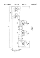
- FIG. 1 describes an energy control system 10 for use with an alternating current (AC) source 60 having a hot wire 62 and a neutral wire 64.
- Energy control system 10 comprises at least one controllable load 110, a master controller 200, a traveler wire 300, and a remote switch 400.
- Controllable load 110 includes a hot terminal 112 and a neutral terminal 114, the latter being coupled to the neutral wire 64 of AC source 60.
- Master controller 200 has an AC input connection 202 coupled to hot wire 62, an AC output connection 204 coupled to the hot terminal 112 of controllable load 110 via a main power wire 310, a traveler connection 206 coupled to traveler wire 300, and an earth ground connection 208 coupled to earth ground 70.
- Master controller 200 is operable to transmit a control command that is received and executed by controllable load 110.
- Remote switch 400 includes a hot connection 404 coupled to the hot terminal 112 of controllable load 110, a traveler connection 406 coupled to traveler wire 300, and an earth ground connection 408 coupled to earth ground 70.
- Remote switch 400 is operable to electrically transmit a remote command to master controller 200 via traveler wire 300.
- Master controller 200 is operable to receive the remote command and to transmit a corresponding control command to controllable load 110.
- traveler wire 300 and main power wire 310 are typically located within the same conduit or cable. That is, traveler wire 300 is not necessarily an additional wire that must be added as part of the installation of energy control system 10. Furthermore, in contrast with many existing energy control systems, master controller 200 and remote switch 400 do not require connections to neutral wire 64. Since neutral wire 64 is often inaccessible at each switchbox in the branch circuit, energy control system 10 is thus well-suited for installation within conventional electrical systems.
- Energy control system 10 is expandable to include multiple remote switches and multiple controllable loads.
- energy control system 10' comprises N remote switches 400, . . . ,480 and a plurality of loads 100 that includes M controllable loads 110, . . . ,160.
- Each of the controllable loads 110, . . . , 160 includes a hot terminal 112, . . . , 162 and a neutral terminal 114, . . . , 164.
- master controller 200 and remote switches 400, . . . , 480 are not limited to those shown in FIG. 2.
- master controller 200 may be positioned to the right of, or interposed between, remote switches 400, . . . , 480 without compromising or otherwise detracting from the functionality of energy control system 10'.
- the plurality of loads 100 may include one or more conventional loads, such as ordinary incandescent lights, that are not subject to control by master controller 200.
- the plurality of loads 100 includes at least two controllable loads and master controller 200 is operable to transmit an individualized command that effects a corresponding control action in only one of the controllable loads, while leaving the other controllable loads unaffected.
- Master controller 200 is also operable to transmit a master command that effects a control action in all of the controllable loads.
- master controller 200 is operable to transmit a group command that effects a control action in at least two, but not all, of the controllable loads.
- energy control system 10' may be employed to provide different levels of control (i.e., individual, group, and master) over a given set of controllable loads.
- master controller 200 comprises a power line transmitter 220, a user interface 240, and a master receiver 260.
- Power line transmitter 220 is coupled between AC input connection 202, AC output connection 204, and earth ground 70.
- Power line transmitter 220 preferably transmits control commands to controllable load 110 by inducing a sequence of depressions 280 in the voltage, V AC , supplied by AC source 60.
- power line transmitter 220 inserts a depression 280 in V AC by coupling AC input connection 202 to earth ground connection 208 for a brief period of time that is preferably on the order of 100 microseconds or less. This causes a relatively large current to flow from AC source 60 to earth ground 70.
- AC source 60 has an internal source impedance 68 (denoted Z s ), the relatively large current that flows produces a considerable voltage drop across source impedance 68, with the result that V AC decreases significantly.
- user interface 240 is coupled to power line transmitter 220 and is operable to accept a user command (entered by way of a keypad or an array of pushbuttons or switches, for example) and to subsequently direct power line transmitter 220 to transmit a corresponding control command to load 110.
- Master receiver 260 coupled between traveler connection 206 and power line transmitter 220, accepts remote commands from remote switch 400 and then directs power line transmitter 220 to transmit corresponding control commands to load 110.
- remote switch 400 comprises a pulse transmitter 414 and a user interface 416.
- Pulse transmitter 414 coupled between hot connection 404 and earth ground connection 408, is coupled to traveler connection 406 and is operable to send remote commands to master controller 200.
- pulse transmitter 414 sends remote commands to master controller 200 by transmitting a predetermined sequence of voltage pulses 418 (denoted V TRAV ) over traveler wire 300.
- User interface 416 which preferably includes a keypad or an array of pushbuttons or switches, is coupled to pulse transmitter 414 and is operable to accept a user command and to direct pulse transmitter 414 to send a corresponding remote command to master controller 200.
- the voltage pulses 418 sent by pulse transmitter 414 are received by master receiver 260, which then directs power line transmitter 220 to transmit a corresponding control command to load 110.
- Remote switch 400 may be implemented in a relatively simple and low-cost manner, with the greater complexity being placed in master controller 200. Since only one master controller 200 is required, this strategy optimizes the cost-effectiveness of the overall system 10 for those applications in which multiple remote switches are employed.
- At least one controllable load 110 comprises a controllable electronic ballast 180 for powering at least one fluorescent lamp 190.
- ballast 180 includes a ground terminal 184 coupled to earth ground 70.
- Ballast 180 also includes a receiver 182 for receiving control commands sent by master controller 200 and is operable, in response to control commands sent by master controller 200, to turn on, turn off, and vary the illumination level of lamp 190.
- remote switch 400 is operable to send remote commands to master controller 200 corresponding to control commands that effect turn on and turn off of ballast 180, as well as adjustment of the illumination level of lamp 190.
- energy control system 20 includes three controllable electronic ballasts 110,120,130 along with their associated lamps (not shown) and two remote switches 400,420.
- master controller 200 and remote switches 400,420 preferably include user interfaces having arrays of pushbuttons by which user commands can be entered.
- the pushbuttons are shown numerically labeled according to their "type,” which uniquely specifies the sequence of pulses that will be sent when that button is pressed.
- button "1" of master controller 200 produces the same sequence of voltage pulses when pressed as button "1" of first remote switch 400.
- master controller 200 executes an appropriate configuration routine that provides: (i) assignment of a unique address to each of the ballasts 110,120,130; and (ii) assignment of a particular control command and a corresponding ballast or group of ballasts to each pushbutton "type" on the user interfaces of master controller 200 and remote switches 400,420.
- a "type 1" pushbutton is assigned to control turn on of all three ballasts 110,120,130, while a "type 9" pushbutton controls increases in the light output of ballast 120 and its associated lamps.
- the configuration routine will typically require interaction of the part of the installer with regard to designating the ballast(s) and control action(s) to be assigned to each pushbutton type.
- the user interfaces of master controller 200, first remote switch 400, and second remote switch 420 are configured to accept various individual, group, and master commands.
- master controller 200 is configured to accept user commands that control: (i) turn on and turn off of all three ballasts 110,120,130 (buttons 1,2); (ii) turn on and turn off of ballasts 120,130 (buttons 3,4); and (iii) dimming of ballast 130 ("arrow" buttons 5,6).
- First remote switch 400 includes pushbuttons that control: (i) turn on and turn off of all three ballasts 110,120,130 (buttons 1,2); and (ii) turn on and turn off of ballasts 1,2 (buttons 3,4).
- remote switch 420 is configured to provide turn on, turn off, and dimming of ballast 120 (buttons 7-10).
- a remote command is sent to master controller 200 by placing a "type 7" sequence of voltage pulses on traveler wire 300.
- the sequence of voltage pulses need only convey enough information to uniquely identify the "type” of the remote button that was pressed.
- Master controller 200 receives the voltage pulses and, by way of a "look-up" table or similar means generated in the configuration routine, identifies the corresponding control command (turn on) as well as the load (ballast #3) for which the control command is intended.
- Master receiver 260 then directs power line transmitter 220 to induce a sequence of depressions in V AC that conveys both the assigned address of ballast 110 and the control command to turn on.
- a power line receiver internal to ballast 130 accepts the control command and directs ballast 130 to execute the control action. Since the sequence of depressions in V AC does not specify their assigned addresses, ballasts 110,120 ignore the control command and thus do not execute any control action in response. In this way, energy control system 10 provides control over an individual load even when multiple controllable loads are present.
- Master controller 200 may likewise be configured to accept user commands corresponding to individualized, group, and master commands.
- buttons 1 and 2 of master controller 200 are assigned to correspond to master ON and master OFF commands.
- master controller 200 induces a sequence of depressions in V AC that specify a master address and a control command to turn on.
- the depressions in V AC are accepted and processed by all three ballasts 110,120,130, with the result that all three ballasts turn on.
- Other pushbuttons on the user interface of master controller 200 are assigned to accept group commands.
- buttons 3 and 4 are assigned to correspond to group commands that effect turn on and turn off of ballasts 120,130, while buttons 5 and 6 are assigned to correspond to group commands that control dimming in ballasts 110,120.
- Master controller 200 may also include functions that are not readily available on its user interface, but that may be accessed via key combinations or special switches.
- master controller 200 may be programmed to automatically implement energy conservation strategies, such as reducing the light output of a certain group of ballasts in response to variation in natural ambient light levels during the daytime, or regularly turning the ballasts off at a certain time (e.g. late evening) and then back on again at another time (e.g. early morning).
- FIG. 5 describes the installation of energy control system 10 within the framework of a standard electrical system that is wired for conventional three-way or four-way switches.
- energy control system 30 comprises a plurality of loads 100, a master controller 200, a traveler wire 300, a main power wire 310, a remote switch 400, a first switchbox 500, and a second switchbox 600.
- the plurality of loads 100 includes multiple controllable loads 110, . . . ,160, each having a hot terminal 112, . . . ,162 and a neutral terminal 114, . . . ,164.
- First switchbox 500 has an input hot connection 502 coupled to hot wire 62, an output hot connection 504 coupled to main power wire 310, a traveler connection 506 coupled to traveler wire 300, and an earth ground connection 508 coupled to earth ground 70.
- Second switchbox 600 has an input hot connection 602 coupled to main power wire 310, an output hot connection 604 coupled to the hot terminals 112, . . . ,162 of controllable loads 110, . . . ,160, a traveler connection 606 coupled to traveler wire 300, and an earth ground connection 608 coupled to earth ground 70.
- master controller 200 is shown installed in first switchbox 500, and remote switch 400 is shown installed in second switchbox 600.
- master controller 200 may just as well be installed in second switchbox 600, and remote switch 400 installed in first switchbox 500, without compromising or otherwise detracting from the resulting functionality of energy control system 30.
- energy control system 30 has an inherent symmetry that greatly simplifies installation by allowing placement of master controller 200 in any available switchbox of the branch circuit.
- main power wire 310 and traveler wire 300 are physically located within the same cable or conduit.
- energy control system 30 is well-suited for retrofit applications and requires no additional wiring or conduit beyond that which is already present in existing three-way and four-way branch circuits.
- energy control system 30 is expandable to accommodate multiple remote switches.
- energy control system 40 includes a second remote switch 420 installed in a third switchbox 700.
- Third switchbox 700 which is electrically situated between first switchbox 500 and second switchbox 600, includes an input hot connection 702 coupled to the output hot connection 504 of first switchbox 500 via main power wire 310, an output hot connection 704 coupled to the input hot connection 602 of second switchbox 600 via a second portion 310' of main power wire 310, a first traveler connection 710 coupled via traveler wire 300 to the traveler connection 506 of first switchbox 500, a second traveler connection 712 coupled via a second portion 300' of traveler wire 300 to the traveler connection 606 of second switchbox 600, and an earth ground connection 708 coupled to earth ground 70. Additional switchboxes and remote switches may be added in an analogous manner.
- master controller 200 may just as well be installed in third switchbox 700, and remote switches 400,420 installed in switchboxes 500,600, with no detriment to system function or performance.
- Energy control system 10 provides a number of important advantages over existing approaches.
- energy control system 10 is a "plug and play" type of system that offers exceptional ease of installation in new buildings and in existing electrical systems.
- energy control system 10 requires no dedicated control wiring, does not require that the master controller 200 be installed in a particular switchbox, and utilizes a single traveler wire 300 (that is already present in existing three-way and four-way switching systems) to convey remote commands from the remote switches 400, . . . ,480 to the master controller 200.
- energy control system 10 provides not only remote on/off control, but other functions such as dimming of fluorescent lamps. The result is an energy control system that offers a full range of control over multiple loads, but that is materially economical and relatively easy to install.
Abstract
Description
Claims (18)
Priority Applications (2)
| Application Number | Priority Date | Filing Date | Title |
|---|---|---|---|
| US08/837,583 US5867017A (en) | 1997-04-21 | 1997-04-21 | Energy control system with remote switching |
| PCT/US1998/000561 WO1998048335A1 (en) | 1997-04-21 | 1998-01-13 | Energy control system with remote switching |
Applications Claiming Priority (1)
| Application Number | Priority Date | Filing Date | Title |
|---|---|---|---|
| US08/837,583 US5867017A (en) | 1997-04-21 | 1997-04-21 | Energy control system with remote switching |
Publications (1)
| Publication Number | Publication Date |
|---|---|
| US5867017A true US5867017A (en) | 1999-02-02 |
Family
ID=25274882
Family Applications (1)
| Application Number | Title | Priority Date | Filing Date |
|---|---|---|---|
| US08/837,583 Expired - Lifetime US5867017A (en) | 1997-04-21 | 1997-04-21 | Energy control system with remote switching |
Country Status (2)
| Country | Link |
|---|---|
| US (1) | US5867017A (en) |
| WO (1) | WO1998048335A1 (en) |
Cited By (15)
| Publication number | Priority date | Publication date | Assignee | Title |
|---|---|---|---|---|
| US6252311B1 (en) | 1998-10-02 | 2001-06-26 | Donald L. West | Load sensor and controller/manager |
| US6380696B1 (en) | 1998-12-24 | 2002-04-30 | Lutron Electronics Co., Inc. | Multi-scene preset lighting controller |
| US6657321B2 (en) * | 2001-10-02 | 2003-12-02 | General Electric Company | Direct current uninterruptible power supply method and system |
| US6693395B2 (en) * | 2001-05-26 | 2004-02-17 | Nextek Power Systems, Inc. | Remote control of electronic light ballast and other devices |
| US20060097890A1 (en) * | 2004-10-28 | 2006-05-11 | Desa Ip, Llc | AC powered wireless control 3-way light switch transmitter |
| US20080106147A1 (en) * | 2006-11-08 | 2008-05-08 | General Electric Company | Apparatus and system for measurement and control of electrical power consumption |
| US20110307309A1 (en) * | 2010-01-29 | 2011-12-15 | Avery Dennison Corporation | Smart Sign Box Using Electronic Interactions |
| US9734365B2 (en) | 2012-09-10 | 2017-08-15 | Avery Dennison Retail Information Services, Llc | Method for preventing unauthorized diversion of NFC tags |
| US9767329B2 (en) | 2012-11-19 | 2017-09-19 | Avery Dennison Retail Information Services, Llc | NFC tags with proximity detection |
| US9858583B2 (en) | 2011-09-01 | 2018-01-02 | Avery Dennison Retail Information Services, Llc | Apparatus, system and method for tracking consumer product interest using mobile devices |
| US9892398B2 (en) | 2011-11-02 | 2018-02-13 | Avery Dennison Retail Information Services, Llc | Distributed point of sale, electronic article surveillance, and product information system, apparatus and method |
| US20180191159A1 (en) * | 2017-01-04 | 2018-07-05 | David Moody | Auxiliary Signaling in Light Switch Traveler Line |
| US10540527B2 (en) | 2012-10-18 | 2020-01-21 | Avery Dennison Retail Information Services Llc | Method, system and apparatus for NFC security |
| US10977969B2 (en) | 2010-01-29 | 2021-04-13 | Avery Dennison Retail Information Services, Llc | RFID/NFC panel and/or array used in smart signage applications and method of using |
| US11074807B2 (en) | 2018-07-03 | 2021-07-27 | George Goin | Remote three-way switch |
Families Citing this family (7)
| Publication number | Priority date | Publication date | Assignee | Title |
|---|---|---|---|---|
| US9303878B2 (en) | 2008-09-15 | 2016-04-05 | General Electric Company | Hybrid range and method of use thereof |
| US8548638B2 (en) | 2008-09-15 | 2013-10-01 | General Electric Company | Energy management system and method |
| US8843242B2 (en) | 2008-09-15 | 2014-09-23 | General Electric Company | System and method for minimizing consumer impact during demand responses |
| US20100207728A1 (en) * | 2009-02-18 | 2010-08-19 | General Electric Corporation | Energy management |
| US8869569B2 (en) | 2009-09-15 | 2014-10-28 | General Electric Company | Clothes washer demand response with at least one additional spin cycle |
| US8943845B2 (en) | 2009-09-15 | 2015-02-03 | General Electric Company | Window air conditioner demand supply management response |
| US8943857B2 (en) | 2009-09-15 | 2015-02-03 | General Electric Company | Clothes washer demand response by duty cycling the heater and/or the mechanical action |
Citations (14)
| Publication number | Priority date | Publication date | Assignee | Title |
|---|---|---|---|---|
| US3558902A (en) * | 1968-01-22 | 1971-01-26 | Everett R Casey | Remote control wiring system |
| US3846671A (en) * | 1973-03-26 | 1974-11-05 | Hunt Electronics Co | Light dimming system for controlling brightness and rate of change of brightness of lights |
| US3868546A (en) * | 1973-03-26 | 1975-02-25 | Hunt Electronics Company | Light dimming system for controlling brightness and rate of change of brightness of lights |
| US4011482A (en) * | 1975-08-28 | 1977-03-08 | Seib James N | Electric circuit control system using exclusive "or" gate |
| US4287468A (en) * | 1978-08-28 | 1981-09-01 | Robert Sherman | Dimmer control system |
| US4377754A (en) * | 1980-03-05 | 1983-03-22 | Pico Electronics Limited | Switching circuit for a remote control system |
| US4525634A (en) * | 1983-05-10 | 1985-06-25 | Southard James S | Alternating current switching device |
| US5031082A (en) * | 1989-11-27 | 1991-07-09 | Bierend Gary D | Remotely controlled security lighting |
| US5170068A (en) * | 1988-09-26 | 1992-12-08 | Lutron Electronics Co., Inc. | Master electrical load control system |
| US5194858A (en) * | 1991-08-29 | 1993-03-16 | The Genlyte Group Incorporated | Lighting control system with set/reset ground remote |
| US5227762A (en) * | 1990-10-26 | 1993-07-13 | Thomas Industries Inc. | Power line carrier controlled lighting system |
| US5373224A (en) * | 1992-03-27 | 1994-12-13 | Sgs-Thomson Microelectronics, S.A. | Method and apparatus for varying the power in a load connected to the mains |
| US5498946A (en) * | 1993-05-05 | 1996-03-12 | Plumer (Societe Anonyme) | Device for controlling the variation of the power and/or the speed of a load |
| US5583423A (en) * | 1993-11-22 | 1996-12-10 | Bangerter; Fred F. | Energy saving power control method |
-
1997
- 1997-04-21 US US08/837,583 patent/US5867017A/en not_active Expired - Lifetime
-
1998
- 1998-01-13 WO PCT/US1998/000561 patent/WO1998048335A1/en active Application Filing
Patent Citations (14)
| Publication number | Priority date | Publication date | Assignee | Title |
|---|---|---|---|---|
| US3558902A (en) * | 1968-01-22 | 1971-01-26 | Everett R Casey | Remote control wiring system |
| US3846671A (en) * | 1973-03-26 | 1974-11-05 | Hunt Electronics Co | Light dimming system for controlling brightness and rate of change of brightness of lights |
| US3868546A (en) * | 1973-03-26 | 1975-02-25 | Hunt Electronics Company | Light dimming system for controlling brightness and rate of change of brightness of lights |
| US4011482A (en) * | 1975-08-28 | 1977-03-08 | Seib James N | Electric circuit control system using exclusive "or" gate |
| US4287468A (en) * | 1978-08-28 | 1981-09-01 | Robert Sherman | Dimmer control system |
| US4377754A (en) * | 1980-03-05 | 1983-03-22 | Pico Electronics Limited | Switching circuit for a remote control system |
| US4525634A (en) * | 1983-05-10 | 1985-06-25 | Southard James S | Alternating current switching device |
| US5170068A (en) * | 1988-09-26 | 1992-12-08 | Lutron Electronics Co., Inc. | Master electrical load control system |
| US5031082A (en) * | 1989-11-27 | 1991-07-09 | Bierend Gary D | Remotely controlled security lighting |
| US5227762A (en) * | 1990-10-26 | 1993-07-13 | Thomas Industries Inc. | Power line carrier controlled lighting system |
| US5194858A (en) * | 1991-08-29 | 1993-03-16 | The Genlyte Group Incorporated | Lighting control system with set/reset ground remote |
| US5373224A (en) * | 1992-03-27 | 1994-12-13 | Sgs-Thomson Microelectronics, S.A. | Method and apparatus for varying the power in a load connected to the mains |
| US5498946A (en) * | 1993-05-05 | 1996-03-12 | Plumer (Societe Anonyme) | Device for controlling the variation of the power and/or the speed of a load |
| US5583423A (en) * | 1993-11-22 | 1996-12-10 | Bangerter; Fred F. | Energy saving power control method |
Non-Patent Citations (2)
| Title |
|---|
| Advertisement for Square D Company Jan., 1977 "Remote Control Relay System". |
| Advertisement for Square D Company Jan., 1977 Remote Control Relay System . * |
Cited By (26)
| Publication number | Priority date | Publication date | Assignee | Title |
|---|---|---|---|---|
| US6252311B1 (en) | 1998-10-02 | 2001-06-26 | Donald L. West | Load sensor and controller/manager |
| US6380696B1 (en) | 1998-12-24 | 2002-04-30 | Lutron Electronics Co., Inc. | Multi-scene preset lighting controller |
| US6545434B2 (en) | 1998-12-24 | 2003-04-08 | Lutron Electronics Co., Inc. | Multi-scene preset lighting controller |
| US6693395B2 (en) * | 2001-05-26 | 2004-02-17 | Nextek Power Systems, Inc. | Remote control of electronic light ballast and other devices |
| US20080211430A1 (en) * | 2001-05-26 | 2008-09-04 | William George Wilhelm | Remote control of electronic light ballast and other devices |
| US20040160197A1 (en) * | 2001-05-26 | 2004-08-19 | Wilhelm William George | Remote control of electronic light ballast and other devices |
| US7312585B2 (en) * | 2001-05-26 | 2007-12-25 | William George Wilhelm | Remote control of electronic light ballast and other devices |
| US6657321B2 (en) * | 2001-10-02 | 2003-12-02 | General Electric Company | Direct current uninterruptible power supply method and system |
| US7656308B2 (en) * | 2004-10-28 | 2010-02-02 | Heathco Llc | AC powered wireless control 3-way light switch transmitter |
| US20060097890A1 (en) * | 2004-10-28 | 2006-05-11 | Desa Ip, Llc | AC powered wireless control 3-way light switch transmitter |
| US20080106147A1 (en) * | 2006-11-08 | 2008-05-08 | General Electric Company | Apparatus and system for measurement and control of electrical power consumption |
| US20110307309A1 (en) * | 2010-01-29 | 2011-12-15 | Avery Dennison Corporation | Smart Sign Box Using Electronic Interactions |
| US10977969B2 (en) | 2010-01-29 | 2021-04-13 | Avery Dennison Retail Information Services, Llc | RFID/NFC panel and/or array used in smart signage applications and method of using |
| US10977965B2 (en) * | 2010-01-29 | 2021-04-13 | Avery Dennison Retail Information Services, Llc | Smart sign box using electronic interactions |
| US10607238B2 (en) | 2011-09-01 | 2020-03-31 | Avery Dennison Corporation | Apparatus, system and method for consumer tracking consumer product interest using mobile devices |
| US9858583B2 (en) | 2011-09-01 | 2018-01-02 | Avery Dennison Retail Information Services, Llc | Apparatus, system and method for tracking consumer product interest using mobile devices |
| US9892398B2 (en) | 2011-11-02 | 2018-02-13 | Avery Dennison Retail Information Services, Llc | Distributed point of sale, electronic article surveillance, and product information system, apparatus and method |
| US9734365B2 (en) | 2012-09-10 | 2017-08-15 | Avery Dennison Retail Information Services, Llc | Method for preventing unauthorized diversion of NFC tags |
| US10282572B2 (en) | 2012-09-10 | 2019-05-07 | Avery Dennison Retail Information Services, Llc | Method for preventing unauthorized diversion of NFC tags |
| US10540527B2 (en) | 2012-10-18 | 2020-01-21 | Avery Dennison Retail Information Services Llc | Method, system and apparatus for NFC security |
| US11126803B2 (en) | 2012-10-18 | 2021-09-21 | Avery Dennison Corporation | Method, system and apparatus for NFC security |
| US10402598B2 (en) | 2012-11-19 | 2019-09-03 | Avery Dennison Retail Information Services, Llc | NFC tags with proximity detection |
| US10970496B2 (en) | 2012-11-19 | 2021-04-06 | Avery Dennison Retail Information Services, Llc | NFC tags with proximity detection |
| US9767329B2 (en) | 2012-11-19 | 2017-09-19 | Avery Dennison Retail Information Services, Llc | NFC tags with proximity detection |
| US20180191159A1 (en) * | 2017-01-04 | 2018-07-05 | David Moody | Auxiliary Signaling in Light Switch Traveler Line |
| US11074807B2 (en) | 2018-07-03 | 2021-07-27 | George Goin | Remote three-way switch |
Also Published As
| Publication number | Publication date |
|---|---|
| WO1998048335A1 (en) | 1998-10-29 |
Similar Documents
| Publication | Publication Date | Title |
|---|---|---|
| US5867017A (en) | Energy control system with remote switching | |
| US5798581A (en) | Location independent dimmer switch for use in multiple location switch system, and switch system employing same | |
| KR0140542B1 (en) | Master electrical load control system | |
| US7498952B2 (en) | Remote control lighting control system | |
| US5905442A (en) | Method and apparatus for controlling and determining the status of electrical devices from remote locations | |
| JP3989551B2 (en) | Repeaters for transmission systems that control and determine the state of electrical equipment from a remote location | |
| US6687487B1 (en) | Repeater for transmission system for controlling and determining the status of electrical devices from remote locations | |
| US5838226A (en) | Communication protocol for transmission system for controlling and determining the status of electrical devices from remote locations | |
| EP1460775B1 (en) | Lighting control with power line modem | |
| WO1997029560A9 (en) | Remotely controlling and determining electrical device status | |
| US5237207A (en) | Master electrical load control system | |
| US7135966B2 (en) | Lighting installation with regulation of light emission devices | |
| US5381078A (en) | Control and communication processor potentiometer system for controlling fluorescent lamps | |
| GB2336045A (en) | Remotely controllable electrical switching apparatus | |
| CN101689771A (en) | Electric load control system having regional receivers | |
| CN220256175U (en) | Mirror with human body induction wireless switch for adjusting light and color and bathroom mirror cabinet | |
| JPS62193095A (en) | Remote monitoring controller | |
| JP3184557B2 (en) | Lighting control device | |
| CN116439551A (en) | Mirror with human body induction wireless switch for adjusting light and color and bathroom mirror cabinet | |
| JP3195659B2 (en) | Remote control system | |
| JP2021158055A (en) | Lighting control system, lighting control method, and program | |
| JPS61274526A (en) | Transmission controlling equipment | |
| JPH0361399B2 (en) |
Legal Events
| Date | Code | Title | Description |
|---|---|---|---|
| AS | Assignment |
Owner name: MOTOROLA, INC., ILLINOIS Free format text: ASSIGNMENT OF ASSIGNORS INTEREST;ASSIGNORS:MERWIN, JEFFREY D.;STEPHENS, DENNIS L.;REEL/FRAME:008752/0962 Effective date: 19970418 Owner name: MOTOROLA, INC., ILLINOIS Free format text: ASSIGNMENT OF ASSIGNORS INTEREST;ASSIGNORS:MERWIN, JEFFREY D.;STEPHENS, DENNIS L.;REEL/FRAME:008527/0246 Effective date: 19970418 |
|
| STCF | Information on status: patent grant |
Free format text: PATENTED CASE |
|
| CC | Certificate of correction | ||
| AS | Assignment |
Owner name: OSRAM SYLVANIA INC., MASSACHUSETTS Free format text: ASSIGNMENT OF ASSIGNORS INTEREST;ASSIGNOR:MOTOROLA, INC.;REEL/FRAME:010648/0827 Effective date: 20000229 |
|
| REFU | Refund |
Free format text: REFUND - PAYMENT OF MAINTENANCE FEE, 4TH YEAR, LARGE ENTITY (ORIGINAL EVENT CODE: R183); ENTITY STATUS OF PATENT OWNER: LARGE ENTITY |
|
| FPAY | Fee payment |
Year of fee payment: 4 |
|
| FPAY | Fee payment |
Year of fee payment: 8 |
|
| FEPP | Fee payment procedure |
Free format text: PAYOR NUMBER ASSIGNED (ORIGINAL EVENT CODE: ASPN); ENTITY STATUS OF PATENT OWNER: LARGE ENTITY |
|
| FPAY | Fee payment |
Year of fee payment: 12 |
|
| AS | Assignment |
Owner name: OSRAM SYLVANIA INC., MASSACHUSETTS Free format text: MERGER;ASSIGNOR:OSRAM SYLVANIA INC.;REEL/FRAME:025546/0415 Effective date: 20100902 |