US5841473A - Image sequence compression and decompression - Google Patents
Image sequence compression and decompression Download PDFInfo
- Publication number
- US5841473A US5841473A US08/732,491 US73249196A US5841473A US 5841473 A US5841473 A US 5841473A US 73249196 A US73249196 A US 73249196A US 5841473 A US5841473 A US 5841473A
- Authority
- US
- United States
- Prior art keywords
- decomposition
- frame
- sequence
- filtering
- image
- Prior art date
- Legal status (The legal status is an assumption and is not a legal conclusion. Google has not performed a legal analysis and makes no representation as to the accuracy of the status listed.)
- Expired - Fee Related
Links
Images


Classifications
-
- H—ELECTRICITY
- H04—ELECTRIC COMMUNICATION TECHNIQUE
- H04N—PICTORIAL COMMUNICATION, e.g. TELEVISION
- H04N19/00—Methods or arrangements for coding, decoding, compressing or decompressing digital video signals
- H04N19/60—Methods or arrangements for coding, decoding, compressing or decompressing digital video signals using transform coding
- H04N19/63—Methods or arrangements for coding, decoding, compressing or decompressing digital video signals using transform coding using sub-band based transform, e.g. wavelets
- H04N19/635—Methods or arrangements for coding, decoding, compressing or decompressing digital video signals using transform coding using sub-band based transform, e.g. wavelets characterised by filter definition or implementation details
-
- H—ELECTRICITY
- H04—ELECTRIC COMMUNICATION TECHNIQUE
- H04N—PICTORIAL COMMUNICATION, e.g. TELEVISION
- H04N19/00—Methods or arrangements for coding, decoding, compressing or decompressing digital video signals
- H04N19/60—Methods or arrangements for coding, decoding, compressing or decompressing digital video signals using transform coding
- H04N19/61—Methods or arrangements for coding, decoding, compressing or decompressing digital video signals using transform coding in combination with predictive coding
-
- H—ELECTRICITY
- H04—ELECTRIC COMMUNICATION TECHNIQUE
- H04N—PICTORIAL COMMUNICATION, e.g. TELEVISION
- H04N19/00—Methods or arrangements for coding, decoding, compressing or decompressing digital video signals
- H04N19/60—Methods or arrangements for coding, decoding, compressing or decompressing digital video signals using transform coding
- H04N19/63—Methods or arrangements for coding, decoding, compressing or decompressing digital video signals using transform coding using sub-band based transform, e.g. wavelets
-
- H—ELECTRICITY
- H04—ELECTRIC COMMUNICATION TECHNIQUE
- H04N—PICTORIAL COMMUNICATION, e.g. TELEVISION
- H04N19/00—Methods or arrangements for coding, decoding, compressing or decompressing digital video signals
- H04N19/10—Methods or arrangements for coding, decoding, compressing or decompressing digital video signals using adaptive coding
- H04N19/102—Methods or arrangements for coding, decoding, compressing or decompressing digital video signals using adaptive coding characterised by the element, parameter or selection affected or controlled by the adaptive coding
- H04N19/115—Selection of the code volume for a coding unit prior to coding
-
- H—ELECTRICITY
- H04—ELECTRIC COMMUNICATION TECHNIQUE
- H04N—PICTORIAL COMMUNICATION, e.g. TELEVISION
- H04N19/00—Methods or arrangements for coding, decoding, compressing or decompressing digital video signals
- H04N19/10—Methods or arrangements for coding, decoding, compressing or decompressing digital video signals using adaptive coding
- H04N19/134—Methods or arrangements for coding, decoding, compressing or decompressing digital video signals using adaptive coding characterised by the element, parameter or criterion affecting or controlling the adaptive coding
- H04N19/146—Data rate or code amount at the encoder output
Definitions
- This invention is in the field of data compression, and is specifically directed to the compression of temporal or spatial sequences of images.
- lossless data compression In which repetitive bits in the digital representation of information are combined.
- An example of lossless compression is commonly referred to as "byte packing".
- the defining characteristic of lossless compression is that an exact copy of the input information is obtained upon decompression. Because of this feature, lossless compression is useful in the storage and communication of computer programs, numerical databases, and other information in which exact replication is a requirement.
- the compression ratio achieved from modern lossless compression is relatively low. As a result, the application of only lossless compression to massive data representations, such as motion pictures and seismic surveys, is inadequate to allow real-time communication of the sequences, or significant storage savings.
- Lossy data compression techniques are also known in the art.
- the defining characteristic of lossy data compression is, of course, that the decompressed information cannot exactly match that of the original information; in other words, some information is lost in the compression of the input information.
- Lossy compression techniques can provide very high compression ratios, however, and as such are often used when the information to be compressed does not require exact bit-for-bit replication upon decompression.
- lossy data compression techniques are useful in the compression of video or graphics images, audio signals, and other digital representation of analog information. Lossy compression techniques are often used in combination with lossless compression in these applications.
- lossy data compression techniques may be considered as low-pass filters of the input information.
- High frequency effects in graphics images generally correspond to the edges of shapes in the image, and as such the application of lossy compression to these images is generally reflected as a loss of resolution at the edges of image elements, or by a loss of resolution in those portions of the image that change over time or space, with the low-frequency portions remaining substantially accurate when decompressed.
- the compression technique may therefore be considered as performed in three stages: encoding of the information into a compressible form (generally involving quantization of the information), decomposition of the encoded images, and thresholding of the decomposed images to eliminate the storage or communication of low coefficient values.
- JPEG Joint Photographic Experts Group
- fractal compression divides each image into pixel groups, or tiles, and approximates each tile by either or both a contractive or rotational transformation based upon a reference region of the image, producing a compressed image consisting of a full representation of the reference region plus the transformation operators for each tile.
- Wavelet-based compression techniques are also known in the art, and have been applied to still images and also motion pictures.
- PCT International Patent Application No. PCT/US95/12050 published by WIPO on Mar. 28, 1996 under International Publication Number WO 96/09718, commonly assigned herewith, describes several wavelet-based approaches to the compression of documents, including the use of dual basis wavelet functions, interpolatory wavelets, and wavelet packets.
- FIG. 1 is a functional block illustration of a conventional type of process used in the compression and decompression of sample sequences, such as images. These conventional processes are referred to as "direct-sum decompositions", and are described in Chui, An Introduction to Wavelets (Academic Press, 1992), pp. 141-148, 199.
- An input image frame C i expressed as a sequence of coefficients, is decomposed by two filter functions G(z), H(z) in filter processes 2, 4, followed by downsampling by a factor of two (i.e., eliminating every other coefficient) in processes 3, 5, respectively.
- This decomposition is typically followed by quantization and encoding (not shown in FIG. 1), as is well known in the art, to achieve the desired compression ratio. As shown in FIG.
- filter processes 2, 4, and downsampling processes 3, 5 are performed by the compression system CS.
- the output of filter process 2 and downsampling process 3 is a low-frequency component L of the image
- the output of filter process 4 and downsampling process 5 is a high-frequency component H of the image.
- much of the high frequency component H is eliminated by quantization and thresholding to obtain the desired compression ratio.
- the decompression system DS reconstructs the image by applying upsampling process 7 (i.e., inserting zeroes between adjacent incoming coefficients) and, in process 8, applying a filter function P(z) to low-frequency component L.
- upsampling process 7 i.e., inserting zeroes between adjacent incoming coefficients
- process 8 applying a filter function P(z) to low-frequency component L.
- the high-frequency component H is upsampled in process 9 and is filtered by function Q(z) in process 10.
- the output of filter processes 9, 10 are summed to arrive at the output image C o , which is a close approximation to the input image C i .
- the filter functions G(z), H(z), P(z), Q(z) may be considered as convolution filters.
- the filter function G(z) is of the form: ##EQU1##
- the filter functions H(z), P(z), Q(z) are similarly constructed.
- the coefficients g k , h k , p k , q k are selected according to the desired convolution functions to be applied.
- the decomposition of image C i from the j th level to the j-1th level is obtained by the convolution of the sequence of coefficients ⁇ c j ⁇ with the filter functions G(z), H(z), P(z), Q(z), to generate both a low-frequency sequence ⁇ j-1 ⁇ and a high-frequency sequence ⁇ d j-1 ⁇ , as follows: ##EQU2##
- the index l corresponds to the convolution interval. Reconstruction is performed by the following convolution and sum: ##EQU3##
- the filter functions G(z), H(z), P(z), Q(z) must obey certain constraints in order for the direct-sum decomposition and reconstruction to occur properly. This requires: ##EQU4##
- the decomposition filter functions G(z), H(z), are related to the reconstruction filter functions P(z), Q(z) as follows: ##EQU5##
- the invention may be implemented into a compression and decompression system useful in communication or storage of compressed sequences of images, in either the temporal or spatial domains.
- filtering functions are applied in both the compression and decompression systems that may be performed by relatively simple integer operations.
- a Cholesky filter performed by way of forward and backward differencing, is applied in either the compression or decompression system, depending upon which system has the higher computational capability. This permits either the compression system or the decompression system to be implemented with relatively modest computational power, depending upon the application.
- FIG. 1 is a functional block diagram illustrating a conventional filter scheme for compressing and decompressing images.
- FIG. 2 is an illustration of a sequence of image frames, upon which the preferred embodiments of the invention are operable.
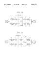
- FIGS. 3a through 3c are functional block diagrams illustrating alternative filter schemes for compressing and decompressing images according to the preferred embodiments of the invention.
- FIGS. 4a and 4b are flow charts illustrating methods of compressing and decompressing sequences of images according to the preferred embodiments of the invention.
- FIGS. 5a and 5b are exemplary computer systems for performing the methods of compressing and decompressing sequences of images illustrated in FIGS. 3a and 3b, respectively.
- FIG. 6 is a flow chart illustrating the method of intraframe decomposition of an image according to the first preferred embodiment of the invention.
- FIG. 7 is a functional block diagram illustrating the filter scheme for intraframe decomposition according to the method illustrated relative to FIG. 6.
- FIGS. 8a through 8d are illustrations of an image at various stages of the intraframe decomposition method of FIG. 6.
- FIGS. 9a through 9c are electrical diagrams, in schematic form, functionally illustrating circuitry or computer operations for performing average and difference filtering as used in intraframe decomposition according to the preferred embodiments of the invention, for various orders of filtering.
- FIG. 10 is a flow chart illustrating an example of the interframe decomposition process performed according to the preferred embodiments of the invention.
- FIGS. 11a and 11b are illustrations of paired compressed images indicating the assignment of quantizer values according to the preferred embodiments of the invention.
- FIGS. 12a through 12d are illustrations of a group of four compressed images indicating the assignment of quantizer values according to the preferred embodiments of the invention.
- FIG. 13 is a flow chart illustrating an example of the interframe reconstruction process performed according to the preferred embodiments of the invention.
- FIG. 14 is a flow chart illustrating the method of intraframe reconstruction according to the method illustrated relative to FIG. 3a.
- FIG. 15 is a functional block diagram illustrating the filter scheme for intraframe reconstruction according to the method illustrated relative to FIG. 6.
- FIGS. 16a through 16e are illustrations of an image at various stages of the intraframe reconstruction method of FIG. 6.
- FIGS. 17a through 17c are electrical diagrams, in schematic form, functionally illustrating circuitry or computer operations for performing average and difference filtering as used in intraframe reconstruction according to the preferred embodiments of the invention, for various orders of filtering.
- FIG. 18 is a flow chart illustrating the method of intraframe decomposition according to the method illustrated relative to FIG. 3b.
- FIG. 19 is a functional block diagram illustrating the filter scheme for intraframe decomposition according to the method illustrated relative to FIG. 18.
- FIG. 20 is a flow chart illustrating the method of intraframe reconstruction according to the method illustrated relative to FIG. 3b.
- FIG. 21 is a functional block diagram illustrating the filter scheme for intraframe reconstruction according to the method illustrated relative to FIG. 20.
- the present invention is useful for the compression and decompression of sequences of images.
- data compression techniques are widely used in the communication of information, particularly in the communication of high volume data sets corresponding to graphic or visual images.
- data compression is useful in the archival storage of digital information to reduce the storage requirements for infrequently used, but important, information.
- it is of course desirable to obtain a high compression ratio (i.e., a high degree of compression), while still maintaining reasonably high fidelity in the decompressed information upon retrieval or receipt.
- the computational complexity as reflected in the computing time or power required to effect the compression and decompression of the information, are also important considerations.
- images may be considered as two-dimensional representations that convey visual information.
- These images which be in monochrome, gray scale, or in color, may correspond to a photograph or frame of a motion picture, or may be a cross-sectional view of a three-dimensional volume.
- each image is a two-dimensional array of picture elements, or pixels, in which each pixel is represented by an intensity value to convey its brightness.
- the simple monochrome image merely uses a single bit per pixel; gray scale monochrome images may use eight or sixteen bits per pixel to convey shades of gray.
- Color images are typically composite images, consisting of red, green, and blue color components corresponding to the red, green, and blue display elements, with each pixel being represented by twenty-four bits (eight per color component).
- Sequences of images consist of an ordered group of two-dimensional images that have a relationship with one another.
- This relationship may be a temporal relationship, as in the case of a motion picture where adjacent images correspond to similar views at adjacent samples in time, or may have a spatial relationship, as in the case of adjacent cross-sectional views corresponding to adjacent slices of a volume.
- FIG. 2 a sequence of image frames C are illustrated for purposes of defining the nomenclature to be used in this description.
- the sequence shown in FIG. 2 consists of an ordered set of n+1 image frames C O through C n .
- Each image frame C is a two-dimensional graphical representation that has a relationship in the third dimension (i.e., the dimension not displayed in each image frame C) with the other image frames C in the sequence.
- This third dimension may be time, as in the case of a motion picture, or spatial, as in the case of a set of cross-sectional slice views.
- Temporal and spatial coordinate systems are illustrated by the sets of axes shown in FIG. 2.
- the temporal system has three dimensions (x, y, t), with each image frame C being an image in the x and y dimensions, and with the sequence of image frames C ordered in time, each corresponding to a sample in time; the temporal system, of course, is applicable to a motion picture.
- the spatial system has three dimensions (x, y, z), with each image frame C being an image in the x and z dimensions, and with the sequence of image frames ordered in space along the y dimension; the spatial system is applicable to a series of cross-sectional slices of an object or a volume.
- Examples of spatial image frame sequences include three-dimensional seismic surveys of portions of the earth, as used in prospecting for oil and gas, computer-aided design (CAD) representations of a solid object, and tomographic images of a portion of the human body, such as are acquired through nuclear magnetic resonance (NMR) or magnetic resonance imaging (MRI).
- NMR nuclear magnetic resonance
- MRI magnetic resonance imaging
- the relationship among the image frames C in the sequence are such that relatively minor changes in the image may be expected between adjacent frames, especially where the motion picture or three-dimensional imaging is of high resolution and fidelity.
- each image frame may be compressed and decompressed according to a formula set consisting of five polynomials in the z-transform domain (i.e., in sampled time).
- the five polynomials include low-pass and high-pass decomposition filter functions P(z), Q(z), respectively, low-frequency and high-frequency reconstruction filter functions A(z), B(z), respectively, and a fifth filter function K(z) which may be merged into either the decomposition process in the compression system, or into the reconstruction process in the decompression system.
- FIG. 3a a filter scheme according to a first preferred embodiment of the invention will be described, incorporating the filter functions described hereinabove.
- input image frame C i is filtered by low-pass filter function P(z) in process 12, and is then downsampled in process 13 to result in a low-frequency component L; similarly, input image frame C i is filtered by high-pass filter function Q(z) in process 14 and downsampled in process 15 to yield a high frequency component H.
- Low-frequency component L and high-frequency component H are filtered in process 16 by filter function 1/K(z), also occurring within the compression system CS as shown in FIG. 3a. Quantization, thresholding, and encoding of the output of filter process 16 prior to storage or transmission is then performed, as conventional in the art.
- the low-frequency component L is upsampled in process 17 (by inserting zeroes between adjacent coefficients in the sequence), and applied to filter function A(z) in process 18; similarly, high-frequency component H is upsampled in process 17 and filtered by filter function B(z) in process 20.
- the output sequences from filter processes 18, 20 are summed into output image frame C o , which is a faithful representation of the input image frame C i .
- filter functions P(z), Q(z), K(z), A(z), B(z) can result in filter functions P(z), Q(z), A(z), B(z) being relatively simple in the computational sense, and in filter function K(z) being mergeable into either the decomposition process or the reconstruction process.
- a set of filter functions P(z), A(z) that correspond to m th order averaging, filter functions Q(z), B(z) that correspond to m th order differencing, and filter function K(z) that corresponds to Cholesky decomposition provides these properties.
- FIG. 3b in which like reference numerals refer to like processes as in FIG. 3a.
- Cholesky decomposition filtering process 16' in which the filter function 1/K(z) is applied, is now performed by decompression system DS, prior to upsample processes 17, 19, and as such is merged within the decompression or reconstruction process in generating the decompressed image C o .
- the present invention provides the important capability of moving this filtering process into either the compression or decompression systems, depending upon where the desired computational complexity is needed.
- FIG. 3c illustrates this alternative process, in which Cholesky decomposition filter process 16" is shown as being after upsample processes 17, 19. This permissible modification is because a polynomial ⁇ (z) exists where, for m even:
- the preferred embodiments of the invention include a first embodiment of the invention in which the Cholesky decomposition is merged within the decomposition processes performed by the compression system, and a second embodiment of the invention in which the Cholesky decomposition is merged within the reconstruction processes performed by the decompression system.
- FIG. 4a a method of compressing and decompressing a sequence of images according to a first preferred embodiment of the invention, specifically in which the Cholesky decomposition is performed within the compression system is illustrated.
- This method begins with process 22, in which the image frames are digitized upon capture (if not already in a digital form, as is the case with computer-generated images such as those used in seismic surveys).
- the digitized frames each consist of an array of pixels, each pixel represented by a number of bits ranging from one (monochrome) to twenty-four (full color), depending upon the nature of the image and processing desired.
- Intraframe decomposition process 24 may be performed multiple times on each frame, depending upon the compression ratio desired.
- Intraframe decomposition process 24 incorporates the Cholesky decomposition process, and as such corresponds to the filter scheme described hereinabove relative to FIG. 3a, where filter process 16 is performed in the compression system. According to the preferred embodiments of the present invention, and as will be described in further detail hereinbelow, the decomposition is performed both in the horizontal and vertical direction. Process 24 thus generates multiple sequences of coefficients corresponding to various low-frequency and high-frequency components of the frame.
- decision 25 is performed to determine if additional image frames in the sequence are to be decomposed; if so, process 26 selects the next image frame for decomposition, and intraframe decomposition process 24 is repeated for that next frame.
- Interframe decomposition process 28 Upon completion of intraframe decomposition process 24 for all of the frames in the sequence (i.e., decision 25 is NO), interframe decomposition process 28 is next performed.
- Interframe decomposition process 28 according to the preferred embodiments of the invention, combines adjacent decomposed image frames with one another to achieve additional compression, again producing sequences of coefficients corresponding to low-frequency and high-frequency components of the frames.
- the interframe decomposition is enabled by the realization that adjacent frames in time or space, when representative of real time or spatial sequences with a reasonable degree of resolution, generally vary only slightly relative to one another. Accordingly, as will be noted hereinbelow, additional compression may be obtained in the low-frequency and high-frequency decomposition of adjacent pairs or small groups of frames, as performed in process 28.
- Process 30 includes quantization of the coefficients generated from processes 26, 28, which effectively reduces the number of bits required for the representation of each coefficient value. This quantization may also include thresholding of the coefficient values, such that coefficients of a magnitude below a certain threshold value are zeroed; this quantization typically reduces the volume of data required for representation of the higher frequency components of the decomposition. Process 30 also includes the necessary formatting of the coefficient sequences into a bit stream or other format suitable for the communication or archival storage of the sequence.
- all processes up to and including process 30 are performed by the compression system, as indicated by the CS/DS boundary of FIG. 4a.
- the decompression of the image sequences begins with process 32 in which the bit stream is received and decoded by the decompression system, and placed into a form suitable for reconstruction of the image sequence.
- Process 34 is next performed by the decompression system to perform interframe reconstruction, in effect performing the inverse of interframe decomposition process 28 performed by the compression system in process 28.
- the results of interframe reconstruction process 34 are coefficient sequences assigned to individual image frames.
- Intraframe reconstruction process 36 is performed on the coefficient sequences corresponding to individual frames, on a frame-by-frame basis.
- Intraframe reconstruction process 34 corresponds substantially to the inverse of intraframe decomposition process 24 performed by the compression system, except that the Cholesky filtering process need not be included in process 34, as illustrated relative to the filter scheme of FIG. 3a. According to this embodiment of the invention, therefore, the computational load placed upon the decompression system is relatively light, as only the application of the A(z), B(z) filters (i.e., processes 18, 20 of FIG. 3a) is required in intraframe reconstruction process 36.
- decision 37 determines whether additional frames remain to be reconstructed.
- process 38 advances to the next frame for application to intraframe reconstruction process 36.
- process 40 may be performed to store or display the sequence of images in the manner desired.
- the computational complexity of the compression and decompression process may be concentrated in the compression system. Distribution of the computing load toward the compression system is particularly beneficial in particular system environments, an example of which will now be described in FIG. 5a.
- image source 42 corresponds to a video camera or other input providing motion pictures, a digital storage device containing a data base of seismic survey data or series of tomography images, or any other similar source of a sequence of images to be compressed for communication, under the control of local computer 44.
- Local computer 44 may perform the digitization process 22 illustrated in FIG. 4a.
- the sequence of images are forwarded to compression file server 46, which may be a high-performance workstation or other similarly powerful computer.
- compression file server 46 performs the compression processes 24 through 30, including the Cholesky decomposition processes described hereinabove, storing the compressed image sequences in image storage 48, which may be a bank of fixed disk storage or other high density, high volume computer storage.
- Decompression systems DS 0 through DS 2 represent a group of remote computing devices for decompressing and displaying sequences of images communicated thereto from compression file server 46.
- Decompression systems DS 0 through DS 2 may therefore correspond to home theater systems for showing video-on-demand, remote user terminals in a network, personal computers accessing compression file server 46 over the Internet, or the like.
- decompression systems DS 0 through DS 2 may be computing devices of relatively modest power and performance, considering that the computational requirements of the compression process are concentrated in compression file server 46, while still permitting the viewing of the sequences of images at high resolution and high speed (including real-time decompression of motion pictures). This ability to enable decompression using display systems of modest computing power is an important benefit provided by the present invention.
- FIG. 4b illustrates an analogous method to that of FIG. 4a, using like reference numerals for similar processes.
- the input frames are again digitized in process 22, and forwarded individually to intraframe decomposition process 24'.
- Intraframe decomposition process 24' in this embodiment of the invention does not include the Cholesky decomposition filtering process, and thus corresponds to the filter scheme illustrated in FIG. 3b.
- Process 24' is performed on individual frames as before, until no frames remain to be processed (i.e., decision 25 is NO), following which interframe decomposition process 28, and quantization and encoding process 30, are performed as before.
- decision 25 is NO
- interframe decomposition process 28, and quantization and encoding process 30, are performed as before.
- Each of these processes are performed by the compression system, which may be of relatively modest capability as will be illustrated hereinbelow.
- the decompression of the image sequences begins, as before, with decoding process 32 performed by the decompression system.
- Interframe reconstruction process 34 is performed as the inverse of interframe decomposition process 28, to produce coefficient sequences corresponding to individual frames of the compressed sequence.
- intraframe reconstruction process 36' which includes the Cholesky filtering indicated by the filter scheme of FIG. 3b.
- Intraframe reconstruction process 36' is repeated for each of the frames in the sequence (via decision 37 and process 38), following which the sequence of image frames has been restored, and is available for storage and display in process 40.
- FIG. 4b The method of FIG. 4b according to this embodiment of the invention is particularly well suited for use in environments where only modest computing capability may be available for the compression system.
- An example of such an arrangement is illustrated in FIG. 5b, where image source 42 again corresponds to a video camera, data base, or other source of image sequences.
- compression system CS receives the sequences of images from image source 42, performs the compression processes 22 through 30 of FIG. 4b, and transmits the compressed image sequences to decompression file server 50.
- the arrangement of FIG. 5b is particularly useful in the compression of image sequences obtained at remote locations in real time, such as the acquisition of seismic survey signals in the field, and the communication of video images from outer space.
- Decompression file server 50 in the system of FIG. 5b performs processes 32 through 40 illustrated in FIG. 4b, including the Cholesky filtering according to the filter scheme of FIG. 3b. As such, it is contemplated that decompression file server 50 is a relatively high performance workstation that is well-suited for complex computational tasks. Decompression file server 50 stores the results of the decompression processes in image store 52, for later retrieval and viewing by user system 50 coupled thereto.
- the computational burden is concentrated within the decompression system. This permits the compression system to be relatively modest, which is of particular benefit in many situations.
- FIGS. 5a and 5b are, of course, presented by way of example only. It is contemplated that many variations upon these examples will become readily apparent to those of ordinary skill in the art having reference to this description.
- a home computer system may serve as a compression system in uploading motion picture sequences (e.g., home videos) to an Internet server, while serving as a decompression system in receiving motion pictures from a video-on-demand service; in each case, the computationally complex Cholesky decomposition may be located in the servers, rather than in the home computer system.
- FIG. 4a describes a method of compressing and decompressing a sequence of images according to the first preferred embodiment of the invention, specifically in which the Cholesky decomposition is performed within the compression system.
- Digitization process 22 is first performed as noted hereinabove, according to conventional techniques for rendering a digital representation of sequences of images. Of course, if the sequences of images are initially produced digitally, digitization process 22 will be inherent in the production of the sequences. Upon the digitization of the image frames to be compressed, intraframe decomposition process 24 is next performed according to this embodiment of the invention. Referring now to FIGS. 6, 7, and 8a through 8d, intraframe decomposition process 24 according to this embodiment of the invention will now be described in detail.
- FIG. 8a illustrates this single frame C i ; as noted above, frame C i is constructed as an array of pixels arranged in rows and columns, with the image information represented by one or more bits per pixel.
- frame C i is a two-dimensional sequence of coefficients ⁇ c m ,n ⁇ , each coefficient corresponding to a pixel in the image, with the index m corresponding to the row in which the pixel resides, and the index n corresponding to the column in which the pixel resides.
- the two-dimensional array will be decomposed into a sequence of coefficients in both the row and column directions; in this example, row-wise decomposition is performed first, followed by column-wise decomposition.
- row-wise decomposition is performed first, followed by column-wise decomposition.
- column-wise decomposition may be performed first, followed by row-wise decomposition, with equivalent results.
- process 56 is next performed, in which row-wise average and difference filtering is applied to the input frame C i .
- filtering process 56 includes the application of m th order average filter P(z) and m th order difference filter Q(z) to input frame C i , performed in the row-wise direction in this example.
- the filter functions P(z), Q(z) are derived from the generalized polynomials described hereinabove, depending upon the order of filtering desired.
- filtering process 56 may be performed by way of relatively simple digital filter techniques, for example as performed by a digital signal processor, or by way of specific custom computer hardware designed to perform the filter of the desired order.
- the input coefficient sequence ⁇ c n ⁇ is received at input node INP, and is applied to delay stage 69 (corresponding to the factor z in the z-transform domain); input mode INP is also connected directly to summation nodes 72, 74.
- the output of delay stage 69 is connected to delay stage 71, and to the input of multiplier 70.
- Multiplier 70 multiplies the coefficient presented to its input by a factor of two, which may be accomplished by a simple left-shift of each digital coefficient value received.
- the output of multiplier 70 is applied directly to summation node 72, and to summation node 74 via inverter 73.
- the output of second delay stage 71 is applied to both of summation nodes 72, 74.
- the output of summation node 74 on line DIFF thus corresponds to the second order difference filtering of the input sequence ⁇ c n ⁇ ; for each input coefficient c n , the difference value on line DIFF is the sum c n -2c n-1 +c n-2 .
- summation node 72 is delayed by an additional delay stage 75, and is presented on line AVG as the second order average c n-1 +2c n-2 +c n-3 ; the additional delay stage 75 for the second order sum is required for this even-numbered order average and difference filtering.
- FIG. 9b illustrates a functional hardware implementation of the third-order difference and averaging filtering.
- input node INP is applied directly to summation node 84 and also to delay stage 77.
- the output of delay stage 77 is applied to x3 multiplier 78, the output of which is applied to summation nodes 84, 86.
- Second delay stage 79 also receives the output of delay stage 77, and has an output applied to x3 multiplier 80.
- the output of multiplier 80 is applied to summation node 82, along with input node INP; the output of summation node 82 has its sign changed by inverter 83, and is then applied to summation mode 86.
- Third delay stage 81 receives the output of second delay stage 79, and applies its output to summation nodes 84, 86.
- the output of summation node 84 is the third order average c n +3c n-1 +3c n-2 +c n-3
- the output of summation node 86 is the third order difference (oppositely signed) -c n +3c n-1 -3c n-2 +c n-3 . Accordingly, the hardware realization of third order difference and averaging filter process 56 is also relatively straightforward, and involves only integer processes.
- FIG. 9c illustrates a hardware realization of these fourth order average and difference filter functions.
- Input node INP is applied to summation nodes 94, 96 directly, and also to delay stage 87.
- the output of delay stage is multiplied by four via a pair of single-bit left-shift multipliers 88, 90, with the output of multiplier 90 applied directly to summation node 94 and via sign change inverter 91 to summation node 96.
- a second delay stage 89 receives the output of delay stage 87, and applies its output to x6 multiplier 92, the output of which is applied directly to both of summation nodes 94, 96.
- Third delay stage 93 receives the output of second delay stage 89, and applies its output to a pair of single-bit left-shift multipliers 94, 96, with the output of multiplier 96 applied directly to summation node 94 and via sign-change inverter 97 to summation node 96.
- a fourth delay stage 95 receives the output of third delay stage 93, and has its output connected directly to summation nodes 94, 96.
- the output of summation node 94 on line AVG thus corresponds to the fourth-order average c n +4c n-1 +6c n-2 +4c n-3 +c n-4
- the output of summation node 96 on line DIFF corresponds to the fourth-order difference c n -4c n-1 +6c n-2 -4c n-3 +c n-4 .
- process 56 is performed by applying each row of image frame C i as a sequence of coefficients ⁇ c n ⁇ to input node INP of a circuit implementation such as that illustrated in FIGS. 9a, 9b, 9c, or the like.
- the average output AVG is then forwarded to downsample process 58a, in which alternate coefficients from the averaging filtering are discarded; similarly, the difference output DIFF is forwarded to downsample process 58d, in which its alternate coefficients are discarded.
- Cholesky decomposition processes 60a, 60d correspond to the application of the 1/K(z) filter of FIG. 7, using the filter function therefor derived in the general sense, as described hereinabove.
- the application of the appropriate filter function 1/K(z) may be performed by way of a matrix operation, if desired.
- it has been found that the use of forward and backward differencing may be applied, in a recursive manner, in performing processes 60a, 60d.
- a first intermediate sequence ⁇ t n ⁇ is generated by way of forward differencing (i.e., recursively subtracting a prior value in the output sequence) as follows:
- a second intermediate sequence ⁇ s n ⁇ is generated by backward differencing as follows:
- t n and s n may be assumed to be zero if n is far out of the range of the signal, since the value of a is relatively small.
- a second intermediate sequence ⁇ s n ⁇ is generated by backward differencing as follows:
- Processes 60a, 60d are thus performed upon the downsampled average and difference sequences, respectively, as illustrated in FIGS. 6 and 7. Given the recursive nature of the forward and backward differencing operations described hereinabove, and considering that the ⁇ factors are at least non-integer, and may be irrational, it is contemplated that relatively high-performance numerical processing is preferably used for performing the Cholesky decomposition processes. For example, computer workstations that incorporate digital signal processing capability are preferred systems for performing processes 60a, 60d according to this first preferred embodiment of the invention.
- the average and difference coefficient sequences AVG, DIFF, respectively are each transformed by way of forward and backward differencing operations into a low-frequency component L and a high-frequency component H.
- These components L, H are preferably stored as an array of the same size as input frame C i , in a manner corresponding to the rows given rise to the decomposition.
- FIG. 8b illustrates the preferred arrangement of this array, where in each row of the array the left-hand columns correspond to the low-frequency component L output by process 60a for the coefficients in that row of input frame C i , and where the right-hand columns of each row similarly correspond to the high-frequency component H.
- Process 62L is next performed upon low-frequency component L, applying the average and difference filtering described hereinabove for process 56, but in the column-wise direction.
- high-frequency component H is filtered by average and difference filtering process 62H, also in the column-wise direction.
- Each of processes 62L, 62H generate an average output AVG and a difference output DIFF, as before.
- Downsampling is performed upon the average and difference outputs from each of processes 62L, 62H, by way of downsampling processes 64La, 64Ld, 64Ha, 64Hd.
- processes 66La, 66Ld, 66Ha, 66Hd Cholesky decomposition is performed again upon each of the downsampled column-wise average and difference components, in the same manner as described hereinabove for processes 62.
- the input image C i has been decomposed into low and high frequency components in two directions, resulting in four components.
- the high-frequency component H from the row-wise decomposition is decomposed into a low-frequency component HL and a high-frequency component HH; the low-frequency component L is similarly decomposed into a low-frequency component LL and a high-frequency component LH.
- the LL component corresponds to the "blur" image, and thus consists of the low frequency components of the input image C i .
- the other components LH, HL, HH correspond to higher-frequency portions of the image, for example edges of objects and other locations in which the image rapidly changes.
- FIG. 8c illustrates each of components LL 1 , LH 1 , HL 1 , HH 1 .
- Components LH 1 , HL 1 , HH 1 are typically stored in memory at this point, as illustrated by process 68 in FIG. 6. Component LL 1 may also be stored at this point, and intraframe decomposition process 24 stopped for this frame, if an approximate compression ratio of 4:1 is sufficient. If additional compression is desired, as is typical, component LL 1 is again decomposed beginning again with process 56, in similar manner as the original input image C i , resulting in four second-level decomposition components LL 2 , LH 2 , HL 2 , HH 2 as shown in FIG. 8d. Each of components LH 2 , HL 2 , HH 2 are stored in memory. Again, the process may again be repeated upon component LL 2 for further compression, if desired.
- decision 25 is performed in order to determine if additional image frames C i remain to be decomposed. If so, process 26 advances to the next frame, and intraframe decomposition process 24 is performed upon that next frame. Upon completion of the intraframe decomposition for all of the frames in the sequence, control passes next to interframe decomposition process 28.
- Interframe decomposition process 28 performs a transform upon a small group of decomposed frames, preferably a pair of frames, or a group of four frames. It is preferred that the two or four frames decomposed by process 28 be adjacent in time or in space, to take advantage of the relatively small changes among the decomposed frames, such that the bulk of the information will be conveyed by the low-frequency decomposed component therefrom, with much of the high-frequency information being sparse (and thus readily compressible).
- interframe decomposition process 28 includes, at each array position C i ,j therein (the index i indicating row position, and the index j indicating column position), a coefficient value corresponding to one of the low-frequency and high-frequency decomposition components generated in that frame from intraframe decomposition process 24.
- interframe decomposition process 28 includes coefficient averaging process 100, and coefficient difference process 102.
- Process 100 generates an average frame D 0 from frames C 0 , C 1 , having average coefficient D 0 i ,j at each array position generated as follows: ##EQU16##
- process 102 generates a difference frame D 1 from frames C 0 , C 1 , having difference coefficient D 1 i ,j at each array position generated as follows: ##EQU17##
- the difference frame D 1 will typically include many coefficients D 1 i ,j that have zero or low magnitude, considering the temporal or spatial relationship between the adjacent frames C 0 , C 1 .
- a great deal of the average frame D 0 will also have zero or low magnitude.
- frames C 0 , C 1 may be recovered as follows:
- a group of four adjacent decomposed frames C 0 , C 1 , C 2 , C 3 may also be combined in interframe decomposition process 28, by way of a matrix operation.
- This matrix operation is performed multiplying a matrix C i ,j, consisting of an array element C i ,j, from each of the four adjacent decomposed frames C 0 , C 1 , C 2 , C 3 , by an orthogonal coefficient matrix T to derive a matrix D ij , also having four elements D i ,j for each of four transform frames D 0 , D 1 , D 2 , D 3 .
- interframe decomposition process 28 for one example of the four-frame case is as follows: ##EQU18##
- orthogonal matrices may be used for interframe decomposition process 28 when applied to four frames.
- the following matrices T, T -1 may be used for decomposition and reconstruction, respectively.
- other orthogonal matrix pairs may be derived to generate the interframe decomposition for two, four, or more decomposed frames, as may be readily derived by those of ordinary skill in the art.
- Interframe decomposition process 28 is repeated for each group of frames in the sequence, until the entire sequence is complete.
- the compressed transformed frames D are forwarded to quantization and encoding process 30.
- Process 30 quantizes each of the coefficients in compressed transformed frames D according to preselected criteria or techniques.
- Known quantization techniques in the art include simple thresholding (i.e., zeroing all coefficients having a magnitude below a specified threshold), simple scalar quantization (which amounts to rounding off each coefficient to a selected accuracy), JPEG quantization, vector quantization, and the like.
- Quantization of the compressed transformed frames D provides additional compression, especially when coupled with lossless compression as will be described hereinbelow.
- quantization may be incorporated earlier into the process, for example within intraframe decomposition process 28.
- the quantization of process 30 is performed by assigning a quantizer ⁇ for each component, or subband, of each transformed decomposed frame D in each set.
- the selection of the quantizers ⁇ is made according to a preselected weighting as desired for each subband; typically, the higher frequency components are weighted relatively less than are the low frequency, or blur, components.
- FIGS. 11a and 11b illustrate the assignment of quantizers ⁇ for the case of two frame interframe decomposition process 28 described hereinabove, where each frame has been decomposed to two levels.
- the number of quantizers ⁇ will depend upon the number of levels to which each frame has been decomposed in intraframe decomposition process 24.
- each pair of frames C 0 , C 1 are transformed into a pair of transform frames including a sum frame D 0 and a difference frame D 1 .
- FIG. 11a illustrates the assignment of quantizers ⁇ 0 through ⁇ 6 for the subbands within sum frame D 0
- FIG. 11b illustrates the assignment of quantizers ⁇ 7 through ⁇ 11 for the subbands within difference frame D 1 .
- the quantization process in process 30 consists of dividing each coefficient in each of frames D 0 , D 1 by the quantizer ⁇ assigned to the subband within which the coefficient resides. This division serves both to weight the particular subbands with a weighting factor, and also to reduce the number of bits required to represent each coefficient value.
- FIGS. 12a through 12d illustrate the assignment of quantizers ⁇ 0 through ⁇ 27 for the subbands contained within transform frames D 0 , D 1 , D 2 , D 3 , where intraframe decomposition process 24 was performed to two levels, as described above. Again, each quantizer ⁇ is selected according to the desired weighting for that particular subband. In process 30 in this case, each coefficient in each of transform frames D 0 , D 1 , D 2 , D 3 is divided by its respective quantizer ⁇ .
- lossless compression may be applied to the quantized transformed compressed frames D, also as part of process 30.
- the lossless compression utilized in process 30 may be according to any of the known conventional techniques, including Huffman encoding, adaptive Huffman encoding, arithmetic encoding, LSQ coding, and the like.
- process 30 Upon completion of lossless compression, process 30 completes with the encoding of the compressed frame sequence into a bit stream suitable for transmission, archival storage, or other desired application of the compressed data.
- the bit stream preferably contains information regarding the identity and sequence of frames D therein, the type of quantization and type of lossless compression applied in process 30, the type of transforms performed in interframe decomposition process 28 (i.e., two or four frame combinations and identification of the matrix T used) and the like, especially where the decompression systems may be called upon to operate upon compressed image sequences according to varying processes.
- the operation of compression system CS is now complete according to this embodiment of the invention.
- Decompression process begins with process 32 in which the encoded transmitted or archival bit stream is received by decompression system DS.
- the bit stream is first decoded from its bit stream form.
- Lossless decompression is then applied to reconstruct compressed transformed frames T, by performing the inverse of the lossless compression process performed in process 30.
- Process 32 also performs dequantization, or normalization, of the coefficient values to the extent required by the quantization process performed by compression system CS.
- dequantization or normalization
- the dequantization of process 32 will be performed by multiplying each coefficient by the same quantizer ⁇ for its subband.
- the combination of the decoding, lossless decompression, and dequantization of process 32 thus operates to reconstruct decompressed transformed frames D by reversing process 30 applied in compression.
- Interframe reconstruction process 34 is next performed by decompression system DS to transform frames D into the uncombined individual frames C. As described hereinabove relative to process 28, each of the interframe decomposition techniques are fully reversible. Referring to FIG. 13, interframe reconstruction process 34 for the case of the two-frame decomposition of FIG. 10 will now be described.
- interframe reconstruction process 34 includes coefficient summing process 104, and coefficient differencing process 106.
- Process 104 recovers frame C 0 from average frame D 0 and difference frame D 1 by generating the coefficient C 0 i ,j at each array position as follows:
- differencing process 106 generates frame C 1 from frames D 0 , D 1 , by recovering coefficients C 1 i ,j at each array position as follows:
- interframe reconstruction process 34 will be performed by applying the inverse matrix T -1 defined hereinabove to each matrix of four coefficient entries from frames D as follows: ##EQU21## where the matrix T -1 corresponds to the matrix defined hereinabove, and depends upon the combination of constants a, b used in interframe decomposition process 28.
- interframe reconstruction process 34 is performed upon each group of frames in the received image sequence.
- Interframe reconstruction process 34 when complete, thus reconstructs each of individual frames C in decomposed form, ready for processing by intraframe reconstruction process 36, as will now be described.
- FIG. 14 is a flow chart illustrating the operation of intraframe reconstitution process 36 according to this embodiment of the invention, in a manner corresponding to the filter scheme of FIG. 15.
- FIGS. 16a through 16e illustrate the arrangement of subbands, or components, for a two-level decomposed frame as will now be reconstructed in this example.
- intraframe reconstruction process 36 begins with process 108, in which the subbands to be used in the first pass of intraframe reconstruction process 36 are received.
- the subbands LL 2 , LH 2 , HL 2 , HH 2 are retrieved from memory in process 108 in this first pass of intraframe reconstruction process 36 for this frame, as this pass will reconstruct component LL 1 from these frames.
- Components LH 2 , HL 2 , HH 2 which were transmitted and derived in the interframe reconstruction process 34, are not retrieved as of yet.
- Each of the subbands LL 2 , LH 2 , HL 2 , HH 2 are upsampled by a factor of two in the column direction by way of processes 109, in order to derive a full sequence of coefficients in each column.
- the upsampling of processes 109 is performed merely by inserting zero values between alternating coefficients in the sequences retrieved in process 108.
- the coefficient sequences for subbands, or components, LL 2 , LH 2 , HL 2 , HH 2 are then applied to column-wise difference and average combining processes 110. As illustrated in FIGS. 14 and 15, components LL 2 , LH 2 , are combined by process 110 L , while components HL 2 , HH 2 are combined by process 110 H . Processes 110 each apply filter functions A(z), B(z) to the low and high frequency component sequences presented thereto, and sum the results into a combined sequence, in effect performing the inverse of the column and difference averaging processes 62 used in intraframe decomposition process 24 by way of which the compressed frames were generated.
- filter functions A(z), B(z) will, of course, have the same order m as filter functions P(z), Q(z), K(z) applied in compression.
- filter functions A(z), B(z) in general as follows:
- the filter functions A(z), B(z) may be implemented by way of relatively simple digital filters, either in software or in dedicated hardware, and utilizing only integer processes. Since the Cholesky decomposition filtering was performed in the compression process, it need not be performed in decompression, and as such the computing requirements for decompression system DS may be quite modest.
- the input high-frequency coefficient sequence (in the case of process 110 L , component LH; in the case of process 110 H , component HH) is received on line UPH, and applied to a series of delay stages 115, 117, 119.
- the output of delay stage 115 is forwarded to summation node 124.
- the output of delay stage 117 is applied, after sign change by inverter 121, to summation node 120.
- the output of delay stage 119 is also applied to summation node 124.
- the input low-frequency coefficient sequence (component LL in the case of process 110 L ; component HL in the case of process 110 H ) on line UPL is applied to summation node 124, and to delay stage 123.
- the output of delay stage 123 is applied to summation node 120, and to delay stage 125, the output of which is also applied to summation node 124.
- the output of summation node 120 is shifted left by one bit by multiplier 122, and applied to summation node 124.
- the output of summation node 124, on line OUTSEQ, corresponds to an output sequence ⁇ c n-1 ⁇ , generated from input sequences ⁇ c n ⁇ (on line UPL) and ⁇ d n ⁇ (on line UPH), and thus corresponds to the next level of reconstruction.
- line UPH is applied to a series of delay stages 127, 129, 131.
- the output of delay stage 127 has its sign changed by inverter 133, and is then applied to summation node 136; the output of delay stage 129 is also applied to summation node 136.
- the output of delay stage 131 after a sign change by inverter 135, is applied to summation node 140, as line UPH itself directly is applied.
- Line UPL is applied to a series of delay stages 137, 139, 141, and directly to summation node 140.
- summation node 140 The outputs of delay stages 137 and 139 are applied to summation node 136, and the output of delay stage 141 is applied to summation node 140.
- the output of summation node 136 is multiplied by three via multiplier 138, and applied to summation node 140.
- line UPH is received by a series of delay stages 141, 143, 145, 147, 149.
- the outputs of delay stages 143, 147 are inverted in sign by inverters 151, 153, respectively, and applied to summation node 150, the outputs of delay stages 141, 149 are applied directly to summation node 160, and the output of delay stage 145 is applied to summation node 152.
- Line UPL is applied to summation node 160, and is received by a series of delay stages 161, 163, 165, 167.
- the outputs of delay stages 161, 165 are applied to summation node 150, the output of delay stage 163 is applied to summation node 152, and the output of delay stage 167 is applied to summation node 160.
- the output of summation node 150 is multiplied by four, by way of one-bit left-shift units 156, 158, and applied to summation node 160, while the output of summation node 153 is multiplied by six by multiplier 154, and applied to summation node 160.
- FIG. 16b illustrates the composition of frame C i at this stage, following the column-wise reconstruction of components L 2 , H 2 .
- the combining process is then repeated in the row-wise direction, with upsample processes 111 L , 111 H followed by row-wise difference and average combining process 112.
- Process 112 follows the same functional implementation as process 110 described hereinabove, using the implementation of the one of FIGS. 17a through 17c for the order m of the decomposition. Indeed, where the implementation of FIGS. 17a through 17c is made by way of custom hardware, the very same circuitry may be used to perform each of processes 100 L , 110 H , 112.
- component LL 1 is returned in this first pass of reconstruction process 36.
- decision 113 is performed by decompression system DS to determine if additional levels of reconstruction are required for the frame C i at this point. For the case where the condition of frame C i is as shown in FIG. 16c, an additional level of reconstruction is in fact required, as the sequence generated by process 112 corresponds to subband, or component, LL 1 . Decision 113 thus returns a NO, and control passes back to process 108 to repeat a pass of process 36.
- component subbands HL 1 , LH 1 , HH 1 for the current frame are retrieved from memory, and combined with component LL 1 generated in the previous pass through process 36 to reconstruct the image.
- processes 110 generate components L 1 , H 1 as illustrated in FIG. 16d, and process 112 generates the final reconstructed image C i as shown in FIG. 16e.
- the number of passes through process 36 for each image frame C i will depend upon the level of its decomposition during compression. While the above description was provided for the case of two levels of decomposition, it is of course contemplated that fewer or more levels of decomposition may be performed, depending upon the desired compression ratio.
- decision 37 is performed by decompression system DS to determine if additional frames require intraframe reconstruction process 36. If so, decompression system DS advances to the next frame (process 38), and performs intraframe reconstruction process 36 on that frame, to reconstruct the image according to the number of levels of decomposition required.
- the sequence of images is ready for display or storage in its decompressed form, as desired by the user.
- the display of the sequence of images performed in process 40 may occur in a real time manner with the receipt of images in process 32.
- This real-time display indicates that the decompression of each frame may be performed in a manner suitable for the display of compressed video-on-demand, with the motion picture being of a very high resolution, and sufficient compression ratio as to be communicated over conventional telecommunication facilities.
- the present invention is particularly beneficial in that it permits application of the Cholesky decomposition filtering process to be performed in either the compression system or in the decompression system, depending upon the system application and the location of the greater amount of computing resources.
- FIG. 4b a second preferred embodiment of the invention will now be described, in which the Cholesky filtering process is merged within the decompression system, thus greatly simplifying the computing burden placed upon the compression system.
- Intraframe decomposition process 24' is next performed on the individual image frames C i prepared by digitizing process 22. As indicated in FIG. 4b, intraframe decomposition process 24' is performed without incorporating thereinto the Cholesky decomposition filtering process, similarly as in the filter scheme illustrated in FIG. 3b. Referring now to FIGS. 18 and 19 in combination, intraframe decomposition process 24' according to this embodiment of the invention will now be described in detail.
- Intraframe decomposition process 24' begins with receipt of an individual frame C i in process 54, followed by row-wise average and difference filtering process 56.
- Row-wise average and difference filtering process 56 applies the filter functions P(z), Q(z), of order m, to frame C i to generate average and difference sequences AVG, DIFF, respectively, for each row of the image.
- the functional construction of circuitry or computer programs to perform average and difference filtering process 56 (and processes 62) will, as before, depend upon the order m of the filtering, and is preferably configured as described hereinabove relative to FIG. 9a, 9b, or 9c.
- Average and difference sequences are downsampled by a factor of two in processes 58a, 58d, respectively, and applied to column-wise average and difference filtering processes 62L, 62H, respectively.
- Column-wise average and difference filtering processes 62L, 62H each produce average and difference output sequences AVG, DIFF, respectively, as before, which are again downsampled by a factor of two in processes 64.
- the downsampled output from processes 64 correspond to the LL, LH, HL, HH decomposition components, or subbands, of image C i .
- decision 67 is performed to determine whether additional compression is desired, in which case the LL component is reprocessed beginning with row-wise average and differencing process 56 to obtain the next level of decomposition, and the LH, HL, HH components are stored for encoding.
- the LL component is also stored and control passes to decision 25.
- the output of intraframe decomposition process 24' according to this embodiment of the invention is thus similar to that generated by process 24 in FIG. 4a, except that Cholesky decomposition filtering has not yet been applied. The absence of the Cholesky filtering is apparent also from the filter scheme of FIG. 19 for the process of FIG. 18 according to this embodiment of the invention.
- decision 25 and process 26 ensure that each of the frames in the sequence of images is similarly decomposed by intraframe decomposition process 24'.
- interframe decomposition process 28 is performed on adjacent groups of decomposed frames, in the identical manner as that described hereinabove relative to the first embodiment of the invention illustrated in FIG. 4a.
- Quantization, lossless compression, and encoding is then performed in process 30, as described hereinabove, and the operation by compression system CS is then complete with the transmission or storage of the compressed image sequence.
- the decompression process begins with process 32, in which the incoming bit stream representative of the image sequence is received by decompression system DS, and is dequantized, decoded, and subjected to lossless decompression, in the inverse manner appropriate based upon the corresponding operations of process 30.
- Interframe reconstruction process 34 is then performed, in the manner described hereinabove relative to process 34 of FIG. 4a, to yield individual compressed frames C from the transformed compressed frames D generated in interframe decomposition process 28.
- Each frame is then applied to intraframe reconstruction process 36' which, according to this embodiment of the invention, includes the application of the Cholesky filtering (i.e., application of the filter function 1/K(z) described above), as will now be described in detail relative to FIGS. 20 and 21.
- intraframe reconstruction process 36' begins with process 108, in which the desired subband components of the image frame C i to be reconstructed are received from memory, again depending upon the level of decomposition active at this time.
- These subband components include the LL, LH, HL, HH components for the level of decomposition.
- Cholesky filtering process 170 Upon receipt of the appropriate components LL, LH, HL, HH, Cholesky filtering process 170 is applied to each component coefficient sequence individually. As described hereinabove relative to FIG. 6, Cholesky filtering is preferably performed through the use of forward and backward differencing techniques, using the appropriate recursive formulae indicated by the particular order m of filtering. Alternatively, Cholesky filtering process 170 may be performed by way of matrix operations, although the forward and backward differencing method is believed to be more efficient. Following Cholesky filtering process 170, each of the filtered sequences are upsampled by a factor of two in processes 109, by inserting zero coefficients between each adjacent coefficients in the sequences.
- Cholesky filtering process 170 and upsampling processes 109 may be reversed, in which case the Cholesky filtering process would apply the polynomial filter 1/K(z 2 ).
- column-wise difference and average combining processes 110 L , 110 H are applied to the upsampled sequences corresponding to the Cholesky filtered sequences LL, LH, HL, HH.
- processes 110 may be performed by way of circuitry or computer programs implemented according to the functional implementations of FIGS. 17a through 17c, depending upon the order m of the compression.
- the outputs of processes 110 L , 110 H are the L and H components, respectively, for the particular level of reconstruction.
- Cholesky filtering process 172 is again applied to these component sequences L, H, in the same manner as described hereinabove relative to process 170, preferably by way of forward and backward differencing techniques.
- sequences L, H are upsampled by a factor of two in processes 111L, 111H, respectively, by the insertion of zeroes therein.
- Row-wise difference and average combining process 112 is then performed in the same manner as processes 110 described hereinabove, resulting in a sequence of coefficients ⁇ c i ⁇ corresponding to the reconstructed image C i for the particular level of reconstruction. If all levels of reconstruction are not yet complete, as indicated by decision 113, the sequence ⁇ c i ⁇ is applied back to process 108 as the LL component, along with the LH, HL, HH components for that level of decomposition, for an additional pass through process 36'.
- decision 37 (FIG. 4b) is then performed to determine if additional frames remain to be processed, in which case process 38 advances to the next frame and intraframe reconstruction process 36' is performed for that next frame.
- decision 37 is No
- the image sequence is ready for storage or display in process 40.
- decompression system DS undertakes the bulk of the computing burden according to this second embodiment of the invention, since the Cholesky filtering processes 170, 172 are merged into the decompression process. This frees compression system CS from this burden, allowing compression system CS to be implemented with relatively modest capability, reducing its cost.
Abstract
Description
Δ(z)=(P(z).sup.2 +P(-z).sup.2)
Δ(z)=z.sup.-1 (P(z).sup.2 -P(-z).sup.2)
P(z)=1/4+1/2z+1/4z.sup.2
Q(z)=1/4z.sup.-1 -1/2+1/4z
t.sub.n =x.sub.n -αt.sub.n-1, for n= . . . -2, -1, 0, 1, 2, . . .
s.sub.n =t.sub.n -αs.sub.n+1, for n= . . . 2, 1, 0, -1, -2, . . .
y.sub.n =8αs.sub.n, for n= . . . -2, -1, 0, 1, 2, . . .
t.sub.n =x.sub.n -α.sub.1 t.sub.n-1 -α.sub.2 t.sub.n-2 - . . . -α.sub.k t.sub.n-k, for n= . . . -2, -1, 0, 1, 2, . . .
s.sub.n =t.sub.n -α.sub.1 s.sub.n+1 -α.sub.2 s.sub.n+2 - . . . -α.sub.k s.sub.n+k, for n= . . . 2, 1, 0, -1, -2, . . .
α.sub.1 =0.4860288221
α.sub.2 =0.01766480087
C.sub.i,j.sup.0 =D.sub.i,j.sup.0 +D.sub.i,j.sup.1
C.sub.i,j.sup.1 =D.sub.i,j.sup.0 -D.sub.i,j.sup.1
C.sub.i,j.sup.0 =D.sub.i,j.sup.0 +D.sub.i,j.sup.1
C.sub.i,j.sup.1 =D.sub.i,j.sup.0 -D.sub.i,j.sup.1
A(z)=z.sup.-1 P(z)
B(z)=-z.sup.-1 -P(-z)
A(z)=P(z)
B(z)=z.sup.2 Q(z)=zP(-z)
Claims (16)
Priority Applications (1)
| Application Number | Priority Date | Filing Date | Title |
|---|---|---|---|
| US08/732,491 US5841473A (en) | 1996-07-26 | 1996-07-26 | Image sequence compression and decompression |
Applications Claiming Priority (2)
| Application Number | Priority Date | Filing Date | Title |
|---|---|---|---|
| US08/732,491 US5841473A (en) | 1996-07-26 | 1996-07-26 | Image sequence compression and decompression |
| PCT/US1996/012326 WO1997006642A1 (en) | 1995-08-04 | 1996-07-26 | Image sequence compression and decompression |
Publications (1)
| Publication Number | Publication Date |
|---|---|
| US5841473A true US5841473A (en) | 1998-11-24 |
Family
ID=24943716
Family Applications (1)
| Application Number | Title | Priority Date | Filing Date |
|---|---|---|---|
| US08/732,491 Expired - Fee Related US5841473A (en) | 1996-07-26 | 1996-07-26 | Image sequence compression and decompression |
Country Status (1)
| Country | Link |
|---|---|
| US (1) | US5841473A (en) |
Cited By (35)
| Publication number | Priority date | Publication date | Assignee | Title |
|---|---|---|---|---|
| US6070133A (en) * | 1997-07-21 | 2000-05-30 | Battelle Memorial Institute | Information retrieval system utilizing wavelet transform |
| US6222944B1 (en) * | 1998-05-07 | 2001-04-24 | Sarnoff Corporation | Down-sampling MPEG image decoder |
| US6275619B1 (en) | 1997-08-29 | 2001-08-14 | Teralogic, Inc. | System and method for performing wavelet and inverse wavelet transformations of digital data using semi-orthogonal wavelets |
| US20020036710A1 (en) * | 2000-08-08 | 2002-03-28 | Choi Seung Jong | Image display device in digital TV |
| US6384759B2 (en) * | 1998-12-30 | 2002-05-07 | At&T Corp. | Method and apparatus for sample rate pre-and post-processing to achieve maximal coding gain for transform-based audio encoding and decoding |
| US6389074B1 (en) * | 1997-09-29 | 2002-05-14 | Canon Kabushiki Kaisha | Method and apparatus for digital data compression |
| WO2002050769A2 (en) * | 2000-12-21 | 2002-06-27 | The Ohio State Universtiy | Method for dynamic 3d wavelet transform for video compression |
| US6421463B1 (en) * | 1998-04-01 | 2002-07-16 | Massachusetts Institute Of Technology | Trainable system to search for objects in images |
| US6424692B1 (en) * | 1998-01-22 | 2002-07-23 | Kabushiki Kaisha Toshiba | Medical image processing with controlled image-display order |
| US20020107988A1 (en) * | 2001-02-05 | 2002-08-08 | James Jordan | In-line compression system for low-bandwidth client-server data link |
| US6459816B2 (en) * | 1997-05-08 | 2002-10-01 | Ricoh Company, Ltd. | Image processing system for compressing image data including binary image data and continuous tone image data by a sub-band transform method with a high-compression rate |
| US20020140851A1 (en) * | 2001-03-30 | 2002-10-03 | Indra Laksono | Adaptive bandwidth footprint matching for multiple compressed video streams in a fixed bandwidth network |
| US6476811B1 (en) * | 1999-09-01 | 2002-11-05 | Ati International, Srl | Method and apparatus for compressing parameter values for pixels in a display frame |
| US20020172429A1 (en) * | 1994-09-21 | 2002-11-21 | Martin Boliek | Compression and decompression system with reversible wavelets and lossy reconstruction |
| US20030004817A1 (en) * | 2001-06-27 | 2003-01-02 | Conoco Inc | Visual database for linking geography to seismic data |
| US6603884B2 (en) | 1997-05-08 | 2003-08-05 | Ricoh Company, Ltd. | Image processing system for compressing image data including binary image data and continuous tone image data by a sub-band transform method with a high-compression rate |
| US20030161406A1 (en) * | 2002-02-26 | 2003-08-28 | Chulhee Lee | Methods for objective measurement of video quality |
| US6633162B2 (en) * | 2001-08-22 | 2003-10-14 | Ge Medical Systems Global Technology Company, Llc | System and method for filtering frequency encoded imaging signals |
| US20040022447A1 (en) * | 2002-07-31 | 2004-02-05 | General Electric Company | Method and system for image compression and decompression using span of interest of an imaging sequence |
| US20040034475A1 (en) * | 2002-06-14 | 2004-02-19 | Eugen Briemle | Procedure for computing the Cholesky decomposition in a parallel multiprocessor system |
| US6748118B1 (en) * | 2000-02-18 | 2004-06-08 | Intel Corporation | Method of quantizing signal samples of an image during same |
| US20040151390A1 (en) * | 2003-01-31 | 2004-08-05 | Ryuichi Iwamura | Graphic codec for network transmission |
| US6785411B1 (en) * | 1999-08-05 | 2004-08-31 | Matsushita Electric Industrial Co., Ltd. | Image analyzing apparatus and image analyzing method |
| US20050013371A1 (en) * | 2003-07-18 | 2005-01-20 | Samsung Electronics Co., Ltd. | Interframe wavelet video coding method |
| US20050053132A1 (en) * | 2003-09-09 | 2005-03-10 | Mitsubishi Denki Kabushiki Kaisha | Method and apparatus for 3-D subband video coding |
| US20050190955A1 (en) * | 2002-01-02 | 2005-09-01 | Hugh Keith Brown | Opposed orthogonal fusion system and method for generating color segmented MRI voxel matrices |
| US20050195899A1 (en) * | 2004-03-04 | 2005-09-08 | Samsung Electronics Co., Ltd. | Method and apparatus for video coding, predecoding, and video decoding for video streaming service, and image filtering method |
| US6961472B1 (en) * | 2000-02-18 | 2005-11-01 | Intel Corporation | Method of inverse quantized signal samples of an image during image decompression |
| US20060120618A1 (en) * | 2004-12-06 | 2006-06-08 | Canon Kabushiki Kaisha | Image processing apparatus, method of controlling thereof, and program |
| US7123652B1 (en) | 1999-02-24 | 2006-10-17 | Thomson Licensing S.A. | Sampled data digital filtering system |
| US20070053428A1 (en) * | 2001-03-30 | 2007-03-08 | Vixs Systems, Inc. | Managed degradation of a video stream |
| US20100245540A1 (en) * | 2007-12-05 | 2010-09-30 | Canon Kabushiki Kaisha | Image processing apparatus, control method thereof, and program |
| US20130016917A1 (en) * | 2011-07-11 | 2013-01-17 | International Business Machines Corporation | Image Compression |
| US20130121603A1 (en) * | 2002-10-24 | 2013-05-16 | Canon Kabushiki Kaisha | Resolution conversion upon hierarchical coding and decoding |
| US10264263B2 (en) | 2016-07-06 | 2019-04-16 | Morpho Detection, Llc | Systems and methods for compressing image data generated by a computed tomography (CT) imaging system |
Citations (1)
| Publication number | Priority date | Publication date | Assignee | Title |
|---|---|---|---|---|
| US5604824A (en) * | 1994-09-22 | 1997-02-18 | Houston Advanced Research Center | Method and apparatus for compression and decompression of documents and the like using splines and spline-wavelets |
-
1996
- 1996-07-26 US US08/732,491 patent/US5841473A/en not_active Expired - Fee Related
Patent Citations (1)
| Publication number | Priority date | Publication date | Assignee | Title |
|---|---|---|---|---|
| US5604824A (en) * | 1994-09-22 | 1997-02-18 | Houston Advanced Research Center | Method and apparatus for compression and decompression of documents and the like using splines and spline-wavelets |
Non-Patent Citations (10)
| Title |
|---|
| Comon, et al., "An Incomplete Factorization Algorithm for Adaptive Filtering", Signal Processing, vol. 13, No. 4 (1987), pp. 353-360. |
| Comon, et al., An Incomplete Factorization Algorithm for Adaptive Filtering , Signal Processing , vol. 13, No. 4 (1987), pp. 353 360. * |
| Tewfik et al., "Fast Positive Definite Linear Systen Solvers", IEEE Trans. Signal Processing, vol. 42, No. 3 (1994), pp. 572-584. |
| Tewfik et al., Fast Positive Definite Linear Systen Solvers , IEEE Trans. Signal Processing , vol. 42, No. 3 (1994), pp. 572 584. * |
| Tewfik, et al., "Fast Multiscale Statistical Processing Algorithm",25th Asilomar Converence on Signals Systems and Computers, (IEEE,1991), pp. 773-777. |
| Tewfik, et al., Fast Multiscale Statistical Processing Algorithm ,25 th Asilomar Converence on Signals Systems and Computers , (IEEE,1991), pp. 773 777. * |
| Vandendorpe, "Hierarchical Transform and Subband Coding of Video Signals", Signal Processing Image Communication, vol. 4, No. 3 (Elsevier, 1992), pp. 245-262. |
| Vandendorpe, Hierarchical Transform and Subband Coding of Video Signals , Signal Processing Image Communication , vol. 4, No. 3 (Elsevier, 1992), pp. 245 262. * |
| Yuan, et al., "Order-Recursive FIR Smoothers", IEEE Trans. Signal Processing, vol. 42, No. 5 (1994), pp. 1242-1246. |
| Yuan, et al., Order Recursive FIR Smoothers , IEEE Trans. Signal Processing , vol. 42, No. 5 (1994), pp. 1242 1246. * |
Cited By (66)
| Publication number | Priority date | Publication date | Assignee | Title |
|---|---|---|---|---|
| US20020172429A1 (en) * | 1994-09-21 | 2002-11-21 | Martin Boliek | Compression and decompression system with reversible wavelets and lossy reconstruction |
| US6985634B2 (en) | 1997-05-08 | 2006-01-10 | Ricoh Company, Ltd. | Image processing system for compressing image data including binary image data and continuous tone image data by a sub-band transform method with a high-compression rate |
| US6714685B2 (en) | 1997-05-08 | 2004-03-30 | Ricoh Company, Ltd. | Image processing system for compressing image data including binary image data and continuous tone image data by a sub-band transform method with a high-compression rate |
| US6603884B2 (en) | 1997-05-08 | 2003-08-05 | Ricoh Company, Ltd. | Image processing system for compressing image data including binary image data and continuous tone image data by a sub-band transform method with a high-compression rate |
| US6459816B2 (en) * | 1997-05-08 | 2002-10-01 | Ricoh Company, Ltd. | Image processing system for compressing image data including binary image data and continuous tone image data by a sub-band transform method with a high-compression rate |
| US20040114819A1 (en) * | 1997-05-08 | 2004-06-17 | Nekka Matsuura | Image processing system for compressing image data including binary image data and continuous tone image data by a sub-band transform method with a high-compression rate |
| US6070133A (en) * | 1997-07-21 | 2000-05-30 | Battelle Memorial Institute | Information retrieval system utilizing wavelet transform |
| US6275619B1 (en) | 1997-08-29 | 2001-08-14 | Teralogic, Inc. | System and method for performing wavelet and inverse wavelet transformations of digital data using semi-orthogonal wavelets |
| US6600838B2 (en) | 1997-08-29 | 2003-07-29 | Oak Technology, Inc. | System and method for performing wavelet and inverse wavelet transformations of digital data using semi-orthogonal wavelets |
| US6389074B1 (en) * | 1997-09-29 | 2002-05-14 | Canon Kabushiki Kaisha | Method and apparatus for digital data compression |
| US6424692B1 (en) * | 1998-01-22 | 2002-07-23 | Kabushiki Kaisha Toshiba | Medical image processing with controlled image-display order |
| US6421463B1 (en) * | 1998-04-01 | 2002-07-16 | Massachusetts Institute Of Technology | Trainable system to search for objects in images |
| US6222944B1 (en) * | 1998-05-07 | 2001-04-24 | Sarnoff Corporation | Down-sampling MPEG image decoder |
| US6384759B2 (en) * | 1998-12-30 | 2002-05-07 | At&T Corp. | Method and apparatus for sample rate pre-and post-processing to achieve maximal coding gain for transform-based audio encoding and decoding |
| US7123652B1 (en) | 1999-02-24 | 2006-10-17 | Thomson Licensing S.A. | Sampled data digital filtering system |
| US6785411B1 (en) * | 1999-08-05 | 2004-08-31 | Matsushita Electric Industrial Co., Ltd. | Image analyzing apparatus and image analyzing method |
| US6476811B1 (en) * | 1999-09-01 | 2002-11-05 | Ati International, Srl | Method and apparatus for compressing parameter values for pixels in a display frame |
| US6961472B1 (en) * | 2000-02-18 | 2005-11-01 | Intel Corporation | Method of inverse quantized signal samples of an image during image decompression |
| US6748118B1 (en) * | 2000-02-18 | 2004-06-08 | Intel Corporation | Method of quantizing signal samples of an image during same |
| US20070247552A1 (en) * | 2000-08-08 | 2007-10-25 | Choi Seung J | Image display device in digital TV |
| US7839452B2 (en) * | 2000-08-08 | 2010-11-23 | Lg Electronics Inc. | Image display device in digital TV |
| US7215381B2 (en) * | 2000-08-08 | 2007-05-08 | Lg Electronics, Inc. | Image display device in digital TV |
| US20060158552A1 (en) * | 2000-08-08 | 2006-07-20 | Choi Seung J | Image display device in digital TV |
| US7079193B2 (en) * | 2000-08-08 | 2006-07-18 | Lg Electronics Inc. | Image display device in digital TV |
| US20020036710A1 (en) * | 2000-08-08 | 2002-03-28 | Choi Seung Jong | Image display device in digital TV |
| WO2002050769A3 (en) * | 2000-12-21 | 2002-09-19 | Ohio State Universtiy | Method for dynamic 3d wavelet transform for video compression |
| US6801573B2 (en) | 2000-12-21 | 2004-10-05 | The Ohio State University | Method for dynamic 3D wavelet transform for video compression |
| WO2002050769A2 (en) * | 2000-12-21 | 2002-06-27 | The Ohio State Universtiy | Method for dynamic 3d wavelet transform for video compression |
| US20020107988A1 (en) * | 2001-02-05 | 2002-08-08 | James Jordan | In-line compression system for low-bandwidth client-server data link |
| US20060193380A1 (en) * | 2001-03-30 | 2006-08-31 | Vixs Systems, Inc. | Managed degradation of a video stream |
| US20020140851A1 (en) * | 2001-03-30 | 2002-10-03 | Indra Laksono | Adaptive bandwidth footprint matching for multiple compressed video streams in a fixed bandwidth network |
| US8107524B2 (en) | 2001-03-30 | 2012-01-31 | Vixs Systems, Inc. | Adaptive bandwidth footprint matching for multiple compressed video streams in a fixed bandwidth network |
| US9826259B2 (en) * | 2001-03-30 | 2017-11-21 | Vixs Systems Inc. | Managed degradation of a video stream |
| US20070053428A1 (en) * | 2001-03-30 | 2007-03-08 | Vixs Systems, Inc. | Managed degradation of a video stream |
| US20070067226A1 (en) * | 2001-06-27 | 2007-03-22 | Caine Bobby J | Visual database for linking geography to seismic data |
| US7340418B2 (en) * | 2001-06-27 | 2008-03-04 | Conocophillips Company | Visual database for linking geography to seismic data |
| US20030004817A1 (en) * | 2001-06-27 | 2003-01-02 | Conoco Inc | Visual database for linking geography to seismic data |
| US6633162B2 (en) * | 2001-08-22 | 2003-10-14 | Ge Medical Systems Global Technology Company, Llc | System and method for filtering frequency encoded imaging signals |
| US6956373B1 (en) * | 2002-01-02 | 2005-10-18 | Hugh Keith Brown | Opposed orthogonal fusion system and method for generating color segmented MRI voxel matrices |
| US7145336B2 (en) | 2002-01-02 | 2006-12-05 | Hugh Keith Brown | Opposed orthogonal fusion system and method for generating color segmented MRI voxel matrices |
| US20050190955A1 (en) * | 2002-01-02 | 2005-09-01 | Hugh Keith Brown | Opposed orthogonal fusion system and method for generating color segmented MRI voxel matrices |
| US20030161406A1 (en) * | 2002-02-26 | 2003-08-28 | Chulhee Lee | Methods for objective measurement of video quality |
| US7219119B2 (en) * | 2002-06-14 | 2007-05-15 | Eads Deutschland Gmbh | Procedure for computing the Cholesky decomposition in a parallel multiprocessor system |
| US20040034475A1 (en) * | 2002-06-14 | 2004-02-19 | Eugen Briemle | Procedure for computing the Cholesky decomposition in a parallel multiprocessor system |
| US20040022447A1 (en) * | 2002-07-31 | 2004-02-05 | General Electric Company | Method and system for image compression and decompression using span of interest of an imaging sequence |
| US20130121603A1 (en) * | 2002-10-24 | 2013-05-16 | Canon Kabushiki Kaisha | Resolution conversion upon hierarchical coding and decoding |
| WO2004070542A3 (en) * | 2003-01-31 | 2005-03-31 | Sony Electronics Inc | Graphic codec for network transmission |
| US20040151390A1 (en) * | 2003-01-31 | 2004-08-05 | Ryuichi Iwamura | Graphic codec for network transmission |
| US7039247B2 (en) * | 2003-01-31 | 2006-05-02 | Sony Corporation | Graphic codec for network transmission |
| US20060182354A1 (en) * | 2003-01-31 | 2006-08-17 | Ryuichi Iwamura | Graphic codec for network transmission |
| US7376278B2 (en) | 2003-01-31 | 2008-05-20 | Sony Corporation | Graphic codec for network transmission |
| WO2004070542A2 (en) * | 2003-01-31 | 2004-08-19 | Sony Electronics, Inc. | Graphic codec for network transmission |
| US20050013371A1 (en) * | 2003-07-18 | 2005-01-20 | Samsung Electronics Co., Ltd. | Interframe wavelet video coding method |
| US7292635B2 (en) * | 2003-07-18 | 2007-11-06 | Samsung Electronics Co., Ltd. | Interframe wavelet video coding method |
| US20050053132A1 (en) * | 2003-09-09 | 2005-03-10 | Mitsubishi Denki Kabushiki Kaisha | Method and apparatus for 3-D subband video coding |
| US7881374B2 (en) * | 2003-09-09 | 2011-02-01 | Mitsubishi Denki Kabushiki Kaisha | Method and apparatus for 3-D subband video coding |
| US20050195899A1 (en) * | 2004-03-04 | 2005-09-08 | Samsung Electronics Co., Ltd. | Method and apparatus for video coding, predecoding, and video decoding for video streaming service, and image filtering method |
| US8331434B2 (en) * | 2004-03-04 | 2012-12-11 | Samsung Electronics Co., Ltd. | Method and apparatus for video coding, predecoding, and video decoding for video streaming service, and image filtering method |
| US8929436B2 (en) | 2004-03-04 | 2015-01-06 | Samsung Electronics Co., Ltd. | Method and apparatus for video coding, predecoding, and video decoding for video streaming service, and image filtering method |
| US8064710B2 (en) * | 2004-12-06 | 2011-11-22 | Canon Kabushiki Kaisha | Image processing apparatus, method of controlling thereof, and program |
| US20060120618A1 (en) * | 2004-12-06 | 2006-06-08 | Canon Kabushiki Kaisha | Image processing apparatus, method of controlling thereof, and program |
| US20100245540A1 (en) * | 2007-12-05 | 2010-09-30 | Canon Kabushiki Kaisha | Image processing apparatus, control method thereof, and program |
| US8848034B2 (en) * | 2007-12-05 | 2014-09-30 | Canon Kabushiki Kaisha | Image processing apparatus, control method thereof, and program |
| US20130016917A1 (en) * | 2011-07-11 | 2013-01-17 | International Business Machines Corporation | Image Compression |
| US8811756B2 (en) * | 2011-07-11 | 2014-08-19 | International Business Machines Corporation | Image compression |
| US10264263B2 (en) | 2016-07-06 | 2019-04-16 | Morpho Detection, Llc | Systems and methods for compressing image data generated by a computed tomography (CT) imaging system |
Similar Documents
| Publication | Publication Date | Title |
|---|---|---|
| US5841473A (en) | Image sequence compression and decompression | |
| US5703965A (en) | Image compression/decompression based on mathematical transform, reduction/expansion, and image sharpening | |
| Roos et al. | Reversible intraframe compression of medical images | |
| US5014134A (en) | Image compression method and apparatus | |
| US5615287A (en) | Image compression technique | |
| US7076108B2 (en) | Apparatus and method for image/video compression using discrete wavelet transform | |
| US5661822A (en) | Data compression and decompression | |
| US6711299B2 (en) | Wavelet transformation of dithered quantized/reduced color pixels for color bit depth image compression and decompression | |
| US5604824A (en) | Method and apparatus for compression and decompression of documents and the like using splines and spline-wavelets | |
| US5936669A (en) | Method and system for three-dimensional compression of digital video signals | |
| US5883823A (en) | System and method of a fast inverse discrete cosine transform and video compression/decompression systems employing the same | |
| Jasmi et al. | Comparison of image compression techniques using huffman coding, DWT and fractal algorithm | |
| EP0985193B1 (en) | Method and apparatus for wavelet based data compression | |
| Siddeq et al. | A novel image compression algorithm for high resolution 3D reconstruction | |
| EP0988757A1 (en) | System and method for encoding video data using computationally efficient adaptive spline wavelets | |
| US6934420B1 (en) | Wave image compression | |
| Jones et al. | Digital image compression | |
| Karlık | Medical image compression by using vector quantization neural network (VQNN) | |
| Sahooinst et al. | Haar wavelet transform image compression using various run length encoding schemes | |
| US20040136600A1 (en) | Visually lossless still image compression for RGB, YUV, YIQ, YCrCb, K1K2K3 formats | |
| WO1997006642A1 (en) | Image sequence compression and decompression | |
| Aravind et al. | On implementing the JPEG still-picture compression algorithm | |
| Al-Saleem et al. | Improvement of Image Compression by Changing the Mathematical Equation Style in Communication Systems | |
| JP3132171B2 (en) | Decoded image decoding device | |
| Torbey et al. | System for lossless digital image coding/decoding |
Legal Events
| Date | Code | Title | Description |
|---|---|---|---|
| AS | Assignment |
Owner name: HOUSTON ADVANCED RESEARCH CENTER, TEXAS Free format text: ASSIGNMENT OF ASSIGNORS INTEREST;ASSIGNORS:CHUI, CHARLES K.;WANG, JIANRONG;REEL/FRAME:008739/0053;SIGNING DATES FROM 19961016 TO 19961021 |
|
| AS | Assignment |
Owner name: SOFTWARE FOR IMAGE COMPRESSION N.V., NETHERLANDS A Free format text: ASSIGNMENT OF ASSIGNORS INTEREST;ASSIGNOR:HOUSTON ADVANCED RESEARCH CENTER;REEL/FRAME:008715/0228 Effective date: 19970827 |
|
| AS | Assignment |
Owner name: FOTO-WEAR, INC., PENNSYLVANIA Free format text: ASSIGNMENT OF ASSIGNORS INTEREST;ASSIGNOR:SOFTWARE FOR IMAGE COMPRESSION N.V.;REEL/FRAME:010103/0898 Effective date: 19990706 |
|
| AS | Assignment |
Owner name: FOTO-WEAR, INC., PENNSYLVANIA Free format text: SECURITY AGREEMENT;ASSIGNOR:COMPRESSION ENGINE TECHNOLOGIES, INC.;REEL/FRAME:012333/0542 Effective date: 20001201 |
|
| REMI | Maintenance fee reminder mailed | ||
| LAPS | Lapse for failure to pay maintenance fees | ||
| STCH | Information on status: patent discontinuation |
Free format text: PATENT EXPIRED DUE TO NONPAYMENT OF MAINTENANCE FEES UNDER 37 CFR 1.362 |
|
| FP | Lapsed due to failure to pay maintenance fee |
Effective date: 20021124 |
|
| AS | Assignment |
Owner name: ROBINSON, GARY, PENNSYLVANIA Free format text: LIEN;ASSIGNOR:FOTO-WEAR, INC.;REEL/FRAME:017025/0204 Effective date: 20051202 |