US5815097A - Method and apparatus for spatially embedded coding - Google Patents
Method and apparatus for spatially embedded coding Download PDFInfo
- Publication number
- US5815097A US5815097A US08/652,380 US65238096A US5815097A US 5815097 A US5815097 A US 5815097A US 65238096 A US65238096 A US 65238096A US 5815097 A US5815097 A US 5815097A
- Authority
- US
- United States
- Prior art keywords
- data
- bit
- coded data
- compressor
- encoder
- Prior art date
- Legal status (The legal status is an assumption and is not a legal conclusion. Google has not performed a legal analysis and makes no representation as to the accuracy of the status listed.)
- Expired - Fee Related
Links
Images


Classifications
-
- H—ELECTRICITY
- H04—ELECTRIC COMMUNICATION TECHNIQUE
- H04N—PICTORIAL COMMUNICATION, e.g. TELEVISION
- H04N19/00—Methods or arrangements for coding, decoding, compressing or decompressing digital video signals
- H04N19/50—Methods or arrangements for coding, decoding, compressing or decompressing digital video signals using predictive coding
- H04N19/59—Methods or arrangements for coding, decoding, compressing or decompressing digital video signals using predictive coding involving spatial sub-sampling or interpolation, e.g. alteration of picture size or resolution
-
- H—ELECTRICITY
- H03—ELECTRONIC CIRCUITRY
- H03M—CODING; DECODING; CODE CONVERSION IN GENERAL
- H03M7/00—Conversion of a code where information is represented by a given sequence or number of digits to a code where the same, similar or subset of information is represented by a different sequence or number of digits
- H03M7/30—Compression; Expansion; Suppression of unnecessary data, e.g. redundancy reduction
-
- H—ELECTRICITY
- H04—ELECTRIC COMMUNICATION TECHNIQUE
- H04N—PICTORIAL COMMUNICATION, e.g. TELEVISION
- H04N19/00—Methods or arrangements for coding, decoding, compressing or decompressing digital video signals
- H04N19/50—Methods or arrangements for coding, decoding, compressing or decompressing digital video signals using predictive coding
- H04N19/593—Methods or arrangements for coding, decoding, compressing or decompressing digital video signals using predictive coding involving spatial prediction techniques
Definitions
- the present invention relates to the field of data compression and decompression systems; particularly, the present invention relates to compression and decompression systems that operate using coding in the spatial (e.g., pixel) domain.
- Data compression is an extremely useful tool for storing and transmitting large amounts of data. For example, the time required to transmit an image, such as a facsimile transmission of a document, is reduced drastically when compression is used to decrease the number of bits required to recreate the image.
- Compression techniques can be divided into two broad categories, lossy coding and lossless coding.
- Lossy coding involves coding that results in the loss of information, such that there is no guarantee of perfect reconstruction of the original data.
- the goal of lossy compression is the changes to the original data are done in such a way that they are not objectionable or detectable.
- lossless compression all the information is retained and that data is compressed in the manner which allows for perfect reconstruction. It is generally desirable to have a coding scheme that can switch between lossless and lossy without incurring large cost and complexity.
- Bit plane coding and predictive coding are well-known image compression methods for lossless compression. Both bit plane coding and predictive coding operate in the spatial domain directly on pixels. This is unlike many prior art compression schemes that operate in the transform domain. Prior art bit plane and predictive methods either cannot support lossy compression in one-pass encoding or cannot support lossy compression at all.
- the prior art also includes hierarchical coding which is typically broken up into progressive or multi-use encoding.
- hierarchical coding data is encoded in such a way that it is possible to access a given image at different quality levels or resolutions. For example, when searching through an image data base, hierarichal coding allows the user to access lower quality versions of an image in order to determine if the image is the one being sought. If it is, additional data can then be transmitted in stages to further refine the image. This scheme is termed progressive.
- an image database might support a number of different output devices, each having different resolutions.
- a hierarchial coding scheme allows each device to access a version of the image with the appropriate resolution. This is referred to as multi-use.
- a compression/decompression system can support fixed rate applications or fixed size applications.
- the present invention provides a spatially embedded compression/decompression system in a unified lossy/lossless coding scheme that operates in the spatial (e.g., pixel) domain.
- the present invention avoids the costly transformations associated with prior art transform domain in which compression techniques, which are costly with respect to computation and buffering.
- the spatially embedded compression/decompression system of the present invention provides one-pass encoding which supports fixed rate applications in which the lossy/lossless quantization is determined by a limited bandwidth channel, or fixed size applications, in which the lossless/lossy quantization is determined by a limited size storage.
- the present invention provides for embedded compression without the need to store the entire original data during compression.
- a system comprises a one-pass spatially embedded compressor and a limited bandwidth channel.
- the compressor comprises image data into compressed image data in one-pass.
- the compressor comprises an encoder and a coded data manager.
- FIG. 1 is a block diagram of one embodiment of the spatially embedded compression/decompression of the present invention.
- FIG. 2 is a block diagram of a more detailed implementation of one embodiment of the present invention.
- FIG. 3 illustrates an image depicting both high-accuracy (low resolution) and low-accuracy (high resolution) pixels.
- FIG. 4 illustrates an example of constrained interpolation.
- FIGS. 5A and 5B illustrate one embodiment of a bitplane template and a block diagram of one implementation of the template, respectively.
- FIG. 6 illustrates an example of an embedding scheme.
- FIG. 7 illustrates an alternative embodiment of an embedding scheme.
- FIGS. 8A and 8B illustrate bitplane templates.
- FIG. 9 is a block diagram of one embodiment of a context model for prediction coding.
- FIG. 10 illustrates one embodiment of two pixel predictors for an embedded system.
- FIG. 11 illustrates a block diagram of one embodiment of a context model for predictive coding.
- FIG. 12 illustrates a block diagram of a parallel coder chip for predictive coding that includes shifting logic.
- FIG. 13 illustrates one embodiment of an embedding scheme for a system.
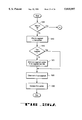
- FIG. 14 illustrates one embodiment of the encoding process of the present invention.
- FIG. 15 illustrates one embodiment of the decoding process of the present invention.
- FIG. 16 illustrates one embodiment of the decorrelate and inverse decorrelate process for predictive coding of the present invention.
- FIGS. 17A and 17B illustrate one embodiment of the process for binarization.
- FIG. 18 is a flow diagram of one embodiment of the process for generating context according to the present invention.
- FIG. 19 is a flow chart of one embodiment of the bucket procedure of the present invention.
- FIG. 20A is a flow diagram of one embodiment of the process for determining the importance level for a bitplane.
- FIGS. 20B-20D are flow charts of one embodiment of the process for determining the importance level for predictive coding.
- FIG. 21A is a flow diagram for one embodiment of the reconstruction process for bitplane coding according to the present invention.
- FIG. 21B is a flow diagram of one embodiment of the reconstruction process for predictive coding.
- FIG. 22 is a flow diagram of the operation of the fixed sized manager in the encoding process.
- FIG. 23 is a flow diagram of the operation of the fixed size manager during decoding.
- FIG. 24 is a flow diagram of the fixed rate data manager during encoding.
- FIG. 25 is a flow diagram of the operation of the fixed rate data manager during decoding.
- FIG. 26A and 26B illustrate the process for allocating a new segment in memory.
- the present invention also relates to apparatus for performing the operations herein.
- This apparatus may be specially constructed for the required purposes, or it may comprise a general purpose computer selectively activated or reconfigured by a computer program stored in the computer.
- the algorithms and displays presented herein are not inherently related to any particular computer or other apparatus.
- Various general purpose machines may be used with programs in accordance with the teachings herein, or it may prove convenient to construct more specialized apparatus to perform the required method steps. The required structure for a variety of these machines will appear from the description below.
- the present invention is not described with reference to any particular programming language. It will be appreciated that a variety of programming languages may be used to implement the teachings of the invention as described herein.
- the present invention provides for compressing and decompressing data using spatially embedded coding.
- the compressed data is ordered based on a metric, such as bit-significance. This is referred to in the art as embedded coding.
- embedded coding This is referred to in the art as embedded coding.
- the present invention uses bit-significance embedded coding in the spatial domain.
- the present invention provides spatially embedded coding by bit-significance ordering.
- bit-significance ordering image (or data) information is arranged into bit planes.
- the bit planes are ordered starting with the most significant bit (MSB) and going towards the least significant bit (LSB).
- MSB most significant bit
- LSB least significant bit
- the elements of each bit-plane are arranged into an order (e.g., raster scan order, etc.).
- spatial embedded coding is performed using a hierarchical scheme based on the assumption that neighboring pixels of an image are strongly correlated and, therefore, the neighboring elements of a bit plane also carry redundant information.
- FIG. 1 illustrates a block diagram of one embodiment of the spatially embedded compression/decompression system of the present invention.
- system 100 comprises a one-pass spatially embedded compressor 101 that receives image data 110 and outputs compressed image data.
- the output of compressor 101 is coupled to a limited bandwidth channel or limited size storage 102 which transfers or stores the compressed data, respectively.
- the limited bandwidth channel/limited size storage 102 is also coupled to spatially embedded decompressor 103 which receives the compressed data, decompresses it, and outputs the decompressed data as an image 111.
- the spatially embedded compression/decompression system of the present invention is a unified lossy/lossless coding scheme that operates in the spatial (e.g., pixel) domain.
- image 111 may be identical to image 100.
- the fixed-size memory e.g., frame store
- the compression is lossless. If the compressed data overflows the compressed data memory, the present invention degrades the image gracefully. In the present invention, there is no (perceivable) scan direction or regional orientation to the degradation, and extreme degradation, such as truncating a portion of the image, is avoided.
- the present invention avoids costly transformations, both as to computational cost and buffering cost associated with the transformations.
- the one-pass encoding of the present invention supports fixed-rate applications in which lossless/lossy quantization is determined by a limited bandwidth channel or fixed-size applications in which lossless/lossy quantization is determined by the limited size storage available in the system.
- FIG. 2 is a block diagram of a more detailed implementation of the embodiment of the present invention illustrated in FIG. 1.
- one-pass spatially embedded compressor 201 comprises one or more encoders 201A coupled to a coded data manager 201B.
- the spatially embedded decompressor 203 comprises a coded data manager 203A coupled to one or more decoders 203B.
- both one-pass spatially embedded compressor 201 and spatially embedded decompressor 203 are coupled to either limited bandwidth channel or limited size storage 202.
- Each one of the one or more encoders 201A produces coded data labeled by importance.
- Coded data manager 201B identifies which data is important and decides, based on a limited bandwidth channel (available bandwidth) or limited size storage (available storage), which data to transmit or store, respectively, and which data to discard, if any.
- coded data manager 201B operates in a decoupled, or independent, manner with respect to the one or more encoders.
- coded data manager 203A and the one or more decoders 203B operate in a decoupled manner.
- Coded data manager 203A obtains data from either limited bandwidth channel or limited size storage 202 and provides the data to the one or more decoders 203B based on the importance level embedded in the data. To that end, coded data manager 203A may provide all of the data or only a portion of the data to the one or more decoders 203B.
- both the spatially embedded compressor and the spatially embedded decompressor operate using a spatially embedded context model (SECM).
- SECM uses a resolution reduction technique to separate the data into a low resolution "high-accuracy” image and a full resolution “low-accuracy” image. Once separated, the present invention codes the low resolution "high-accuracy” pixel losslessly, while coding the high resolution "low accuracy” pixels as accurately as possible based on the channel bandwidth available or the storage size to be used.
- the resolution may be reduced by subsampling, thereby selecting the most important data.
- the present invention generates the high-accuracy image by subsampling (decimate) by two in each dimension which creates an image one-fourth the size. Subsampling is well-known in the art. Thus, the data is decomposed into an "important" part which contains most of the raw information and a "less important" part which contains only the details.
- FIG. 3 illustrates an image depicting both high-accuracy pixels (solid black dots) and low-accuracy pixels (solid white dots).
- the quarter size image comprising the black dots is coded losslessly (or very close to losslessly). Because of the lossless coding, this information is referred to herein as "high accuracy" (image or pixels).
- the other image data comprises the remaining three-quarters of the pixels (shown as the white dots), which are coded as accurately as possible given the size of the compressed data memory or the bandwith of the channel.
- Subsampling has the desirable property of critical sampling. This property is that the total number of pixels (samples) for both the high and low-accuracy images is the same as the number of pixels (samples) in the original image. Subsampling by amounts other than two in each dimension are possible.
- bit stream can be interrupted at any point within the low-accuracy data and bits are located in the stream with smooth details (e.g., more important bits) earlier in the stream than the most important bits, the finer details with are located later in the stream.
- smooth details e.g., more important bits
- the finer details with are located later in the stream.
- missing pixels can be estimated by using interpolation techniques.
- both images undergo compression and the compressed data for the high-accuracy image is separated from the low-accuracy image.
- separation may occur prior to compression.
- the compressed data for the low-accuracy image is embedded. Embedding may also be performed on the high-accuracy image. It should be noted that this separation and embedding is not important if all the coded data can be stored in memory or all the coded data may be transferred (i.e., when lossless coding occurs).
- a high-accuracy image that is one-quarter the size of the original image is good for target compression ratios of up to 4:1, since in the worst case for an incompressible image, it can always be stored exactly. For target compression ratios less than 4:1, there will always be memory available for coarsely representing the low-accuracy image, even in the worst case. If the high-accuracy image is compressed in an embedded function, compression target compression ratios of slightly more than 4:1 can be accommodated. For higher compression ratios, performing more resolution reduction might be desirable. Resolution reduction may be applied recusively to the high-accuracy image.
- the coded data manager determines which data is transmitted or stored based on the limitations of the channel or memory. When a channel is included in the system, the coded data manager must determine which data is to be discarded, if any, prior to data transmission. When a limited memory is involved, memory overflow must be handled. When the memory overflows, some of the coded data for the low-accuracy pixels is overwritten. Since neighboring high-accuracy pixels are known (either exactly or with low error), interpolation, or other prediction techniques, may be used to reconstruct the low-accuracy pixels. Any coded data for the low-accuracy pixels that is not overwritten is used to constrain the interpolation to a range of possible values.
- FIG. 4 illustrates an example of constrained interpolation.
- errors will be constrained to ⁇ 4.
- original pixels 401 are shown with a subset of high accuracy pixels 402.
- a prediction is made on an intervening pixel.
- the prediction is only off by 3. Therefore, the prediction does not have to be constrained by coded data, and the decoded value that results is the predicted value.
- the prediction by interpolation is 151, which is -12 off the actual value of 139. In this case, the prediction is constrained with coded data.
- the constrained value chosen, -8 in this case, is one selected from a group of 0, ⁇ 8, ⁇ 16, etc. It should be noted that the group of 0, -8, ⁇ 16, etc., is sufficient to contain prediction errors to ⁇ 4 as specified in this example.
- the encoder determines what constrained data is necessary.
- the constraint data may be sent and interleaved with other coded data.
- the constrained values may be sent in a block of data which precedes or follows the coded data, or is sent in parallel.
- the encoder may label the data by importance level to identity constrained data. Note that in such a case, the data manager is able to use the importance level information to determine which of data in a data stream is constrained data.
- the spatially embedded compressor performs compression on either bitplanes with a hierarchical, "JBIG-like" (different templates for different phases), context model or on difference values using predictive coding.
- bitplanes with a hierarchical, "JBIG-like" (different templates for different phases), context model or on difference values using predictive coding.
- the low- and high-accuracy images do not have to be coded using the same technique.
- either bitplane or predictive coding may be used. The choice of which technique to use depends, in part, on a trade-off between compression performance and cost of implementation.
- FIG. 5B is a block diagram of one implementation of the template in FIG. 5A. Referring to FIG. 5B, pixels 501 are input to an optional Gray coding block 502. Gray coding is well-known in the art. One useful Gray coding operation is:
- the output of optional Gray coding block 502 is coupled to local buffer 503, which stores the necessary bits for the context.
- local buffer 503 stores the past two decoded bits. These bits may be stored in a shift register. Decoded bits are saved to a line buffer 504 and recalled so that local buffer 503 can also provide five bits from the previous line centered above the current pixel to be coded. These five bits may also be stored in a shift register.
- the outputs of local buffer 503 are a bit to be coded 505 and its context bin 506.
- each bitplane of the data is coded as a separate binary image. Coding "separately" means there are no dependencies so that all (or some) bitplanes may be coded in parallel.
- the context model cycles through each bitplane for a given pixel before moving the template for the next pixel. When bitplanes are coded in parallel, different context bins are used for each bitplane. In this way, the probability estimation for each bitplane may remain separate.
- the embedded system of the present invention separates data of different importance levels.
- the importance levels may be separated, for example, based on bit position or bitplanes. That is, an importance level is associated with the data based on the bit position of the data or in which bitplane the data resides. Since each different importance level adds some complexity, multiple bitplanes may be part of the same importance level. Note that the separation may be performed in software or hardware.
- FIG. 6 shows an example embedding scheme intended for a 2:1 compression in which importance levels are assigned to bits in both the high-accuracy (1/4) pixels and the low-accuracy (3/4) pixels.
- four levels of importance are used.
- Data corresponding to each distinct importance level may be used to form an independent stream that is coded by a distinct coder.
- coding with distinct coders can form independent streams.
- the distinct coder could be a "virtual" decoder in that one coder handles multiple streams for multiple importance levels, as long as separate state information is maintained for each stream.
- zero is the most important level.
- the numerically largest level will be discarded first when memory overflows.
- the amount of data represented by importance level zero may be chosen to allow the most important data to be preserved even if the coding causes a small amount of expansion.
- the system provides graceful degradation for any possible input.
- FIG. 7 illustrates one embodiment of an embedding scheme that might be used for a target compression of 3:1 or 4:1.
- FIGS. 8A and 8B An example set of templates is shown in FIGS. 8A and 8B.
- FIG. 8A illustrates bitplane templates using 20 possible pixels. These templates show available pixels for creating smaller templets, 20 is too many for most applications.
- FIG. 8B illustrates bitplane templates using half (10) of those 20 possible pixels as the context.
- a separate template is used for each of the four phases (0, 1, 2, 3) as in a "JBIG-like" system.
- the line buffer requires multiple lines. In one embodiment, a two line buffer, with some additional memory may be used. Three and four line buffers may also be used.
- the cost of line buffering is not important; for systems with tiling, the buffer must be able to store an entire tile.
- Other templates may be used. Note that to enable parallelism, different bitplanes may need to be processed in parallel, just like in a non-embedded system.
- predictive coding may be used to predict pixels from neighbors and to code the prediction errors.
- An example of predictive coding is referred to as differential pulse coded modulation (DPCM).
- bitplane methods require more context bins for the same compression, and assuming each context bin requires a predetermined number of bits of memory, then the memory for larger bitplane context models has a high hardware cost.
- bitplane context model every bit is entropy coded. Therefore, N-bit data requires N coding operations.
- For predictive coding data some of the data can be assumed to be 50% random data and simply copied to/from the compressed data without needed entropy coding, thereby reducing the entropy coding operations and allowing hardware to operate at faster speeds.
- Third, combining embedding with a predictive coding context model is more difficult if more than a few importance levels are desired.
- Errors cannot be allowed to propagate in a predictive coding system. In one embodiment, only the most important data is used for predictions. This avoids error propagation. If the most important data is not sufficient for making good predictions, either compression will suffer or a significantly more complicated multi-step prediction must be used.
- FIG. 9 is a block diagram of one embodiment of a context model for coding prediction errors.
- pixels 901 are received by local buffer 902.
- Local buffer 902 is coupled to line buffer 903, which provides local buffer 902 with past pixels.
- the output of local buffer 902 is received by predict and determine error (e.g., interpolation block) block 904, which generates a prediction for an incoming bit and determines the error associated with the prediction with respect to the actual value of the bit.
- the prediction is an average of two neighboring high-accuracy pixels. Other prediction methods may be used.
- the output of the predict and determine error block 904 includes a bit to be coded 905 and its context bin 906.
- FIG. 10 illustrates one embodiment of two pixel predictors for the embedded system.
- two additional pixels, 1001 and 1002 may be used in the pixel predictor for phase 1.
- the high-accuracy image is not embedded, and all bits are losslessly coded. Since predictions are made from high-accuracy pixels, error propagation problems are eliminated. However, representing the high-accuracy pixels exactly for all images may result in poor rate/distortion performance.
- the predictive coding scheme may embed the high-accuracy image. Coded data to specify the high resolution pixels to ⁇ 1 is always available. (Note that this is because all of the magnitude and sign bits, with the exception of sign/magnitude bit 0, are coded as importance level 0. See FIG. 13). Even when sufficient coded data is available to know the exact value of a high-accuracy pixel, the result to ⁇ 1 is still determined. All predictions are made using the ⁇ 1 values of the high resolution pixels.
- This scheme is based on two assumptions. First, the information to specify the least significant bit of high resolution pixels is both difficult to compress and of little visual importance. Better rate distortion would be achieved by allocating the same amount of coded data to more visually relevant low-accuracy pixel information. Second, using ⁇ 1 accuracy pixels in the predictor does not significantly reduce the predictor's effectiveness. This assumption is based on the idea that averaging two numbers gains one bit of precision; for example, adding two 7-bit numbers produce a result with 8-bit prediction.
- prediction errors are coded.
- 9-bit prediction errors are used. (Note that while using 8-bit prediction errors can be accomplished with the proper module 256 arithmetic for lossless coding, 9-bit prediction errors are required for lossy coding).
- the method for coding prediction errors takes advantage of two properties: the errors have zero mean and are distributed such that small values are more common than large values.
- FIG. 11 is a block diagram of one embodiment of a context model for predictive coding.
- pixels 1101 are inputted into predictor 1102 which generates a prediction error 1103.
- the prediction error 1103 is converted to a sign magnitude format by sign/magnitude block 1104.
- the magnitude is at times referred to in the art as the category.
- Table 1 illustrates one embodiment of binary magnitudes for 9 bit prediction errors.
- the bits of the pixels in addition to the sign bit and the magnitude that are required to specify the exact value of the error are referred to herein as the mantissa bits (due to the similarity to mantissas in floating point numbers). (The bits are sometimes called "make-up bits” or "tail” bits in the art).
- the output of sign/magnitude block 1104 is coupled to the input of binarize block 1105, which performs binarization (i.e., turns its input into binary).
- the binarization method is selected based on the fact that the bits are going to be compressed.
- a tree is used to perform binarization.
- binarization is performed according to the following method which processes the magnitudes as bitplanes:
- insignifigance identifies bits which occur before the first "one " bit after the sign bit in each pixel.
- insignificance may be based on thresholds, such as those discussed below.
- the output of binarize block 1105 comprises a bit 1107 and is coupled to history block 1106 is optional, generating context bin 1108, and will be discussed below.
- magnitudes are coded with a four bit number (an exponent) which is the base 2 logarithm of the magnitude. This requires only three or four entropy coding operations and eight context bins for the magnitude. The eight context bins are needed for the "zero-order" information that associates a unique probability estimate for each possible magnitude.
- FIG. 12 illustrates a block diagram of a parallel coder chip for predictive coding that includes shifting logic.
- the parallel coder chip of the present invention performs parallel coding.
- One embodiment of an high speed parallel coding chip is described in U.S. Pat. No. 5,381,145, entitled “Method and Apparatus For Parallel Decoding and Encoding of Data", issued Jan. 10, 1995, and assigned to the corporate assignee of the present invention.
- input pixels are received by an input pixel interface 1201 and are supplied to a control model(s) 1202 which, using workspace data, provides contexts to a parallel entropy coder 1206.
- Coder 1206 generates compressed data.
- the compressed data manager 1207 determines which compressed data is output to a channel or memory as described above.
- An optional "no code" path 1205 that allows data to go uncoded to the compressed data manager 1207 for output.
- the data manager 1207 receives compressed data from a channel or memory.
- Context model(s) 1202 using the workspace data, provides contexts to the parallel entropy coder 1206 which decodes the compressed data.
- the decompressed data is output through the output pixel interface 1203. Note that if the data is not compressed, it may be sent through the optional "no code" path 1205.
- FIG. 13 One embodiment of an embedding scheme is shown in FIG. 13, where the first "1" bit in each coefficient is identified by 2 to the number coded minus one. Note that the sign bit is still coded prior to the mantissa bits.
- the notation "sign/magnitude bit(s)” indicates that the sign bit is coded before the most significant bit of the (variable length) mantissa. For example, if the magnitude is 3, mantissa (tail) bits 0 and 1 must be coded and the sign bit is coded in the position assigned to bit 2 of the mantissa. For another example, when the magnitude is 0, no sign or mantissa bits are coded.
- bits 6 . . . 4 of the sign/mantissa are provided by a single shift operation.
- Bits 3 . . . 0 of the sign/mantissa can be provided by low hardware cost shift-by-one or hold shift registers.
- Low accuracy pixel magnitude bits 1 . . . 0 are assigned to either importance level 1 or level 3, depending on whether magnitude bit 2 is 1 or 0, respectively. (See FIG. 13)
- Table 2 The quantization ability of the embedding scheme is summarized in Table 2.
- the context model of the present invention provides context bins for magnitude bits. For nine possible magnitudes, eight context bins (as mentioned above) are sufficient to keep track of the required nine probabilities (since probabilities sum to one). Using only eight context bins provides "zero order" coding of magnitudes. Each magnitude is coded independently of its neighbors under a zero order model. (The neighbors are used for prediction only). Higher order coding can be used so that neighborhood information is used for both prediction and coding. History block 1106 in FIG. 11A provides this neighborhood information. The advantage of neighborhood information is that different probability estimates can be used for smooth regions than those used at edges, which allows better compression.
- Neighborhood information may be the decoded magnitude bits of the pixels used as predictors. All three magnitude bits of one or perhaps two pixels can be used. Alternatively, only one or two bits per pixel can be used. For example, a single bit per pixel can indicate if its magnitude is the same as the current magnitude being decoded. Other choices for neighborhood information include the magnitude of the absolute value of the difference between the two pixels used as a predictor.
- One advantage of embedded predictive coding techniques of the present invention is that it is easy to inject constrained noise in the reconstruction during lossy (including near-lossless) decoding.
- the purpose of injecting noise is to reduce "banding" or “contouring” artifacts (rendering smooth regions of an image with visible discrete regions of differing intensities).
- Injecting noise is a dithering function and might increase quality both for direct printing and printing following a true dithering or halftoning operation.
- coded data should be close to 50% random data if good compression is achieved, it can be used as a source of random bits. Even if the coded data is not exactly 50% random, because there is a lot of it and it is not periodic, it may be a better source than a pseudo-random number generator. And, of course, there is little additional hardware cost.
- the present invention may be performed by processing logic.
- the processing logic may be software running on a computer system or multi-purpose machine and/or specially designed hardware.
- This encoding process is illustrated by a flowchart in FIG. 14. Note than the order of processing pixels may be raster order. The processing may also be performed on 2 ⁇ 2 locks with blocks in raster order (e.g., one pixel each of phases 0, 1, 2 and 3 in sequence).
- pixels may be processed in 2 ⁇ 2 blocks with blocks in raster order (e.g., one pixel each of phases 0, 1, 2 and 3 in sequence).
- the decorrelate and inverse decorrelate process of the present invention is performed using gray-coding. In another embodiment, the present invention does not perform decorrelation.
- the decorrelate and inverse decorrelate process may be performed according to the following pseudo code:
- the north, south, east, west, northwest, southwest, northeast, southeast refers to locations of pixels, with respect to the current pixel, used in the prediction.
- This decorrelate and inverse decorrelate process of the present invention is illustrated by the flowchart in FIG. 16.
- the pixel value associated with the boundary (when its value is needed for prediction) is 0.
- the pixel values associated with the boundary are the same values as below the pixel undergoing prediction in the same manner as if a mirror were placed and running through the pixel undergoing prediction. Decorrelated values are optionally saved for use in conditioning (bucketing).
- binarization is optional because the bits of the pixels may be used themselves.
- bit plane coding one embodiment is as follows, assume 8 bit pixels and "avalue" is the absolute value of the decorrelated value.
- One embodiment of the binarization process is performed according to the following pseudo code:
- variable referred to as num -- category -- bits describes the number of bits to describe the category of the magnitude
- variable referred to as num -- extra -- bits describes the extra -- bits
- the 1 bit describes the sign.
- the category is threshold based. Note that the number of category bits may be variable.
- the number of extra bits refers to the number of bits in the tail, including the sign. In an alternative embodiment, the number of category bits may be 4 for category 6, 7, 8 and 9; and 3 for all the other categories.
- Start is the start of the interval that corresponds to that value, where the value is determined by adding the start value to the number of extra bits.
- the comparison values are start for the next category. More categories or more extra bits per category could be used for pixels larger than 8 bits. Fewer categories or fewer extra bits per category could be used for pixels smaller than 8 bits.
- the inverse binarization follows from the forward.
- the category is used to determine the start of interval and the number of extra bits.
- the start value is added to the value specified by the extra bits.
- the sign bit is used to give the proper sign to the value.
- the present invention generates contexts for each pixel.
- templates are used to generate contexts for each phase.
- performing predictive coding with nine buckets the north, south, etc. are phase 0 decorrelated values (actually, just the category is needed in some embodiments).
- the four category bits are bit 3! . . . bit 0! where bit 3! is the MSB and is coded first.
- Bucketing is known in the art.
- Langdon et al. "Context-dependent Distribution Shaping and Parameterization For Lossless Image Compression", SPIE, Applications of Digital Image Processing XVII vol. 2298, Jul. 26-29 1994, San Diego, Calif.;
- JPEG Still Image Data Compression Standard
- pg. 208 and International Standard Dis 10918-1, CCITT Recommendation T.81, entitled Digital Compression and Coding of Continuous-Tone Still Images, pg. 457, commonly referred to as "JPEG”.
- JPEG Joint Photographic Experts Group
- the importance level may be determined according to the following:
- the importance level may be determined accordig to the following:
- FIGS. 20B through 20D The process for determining the importance level above is shown in FIGS. 20B through 20D.
- reconstruction is used to adjust the binarization when all bits of the binarization are not known.
- reconstruction is performed according to the following:
- the valid range is 0-255, which is known by both the encoder and the decoder.
- the process for reconstruction described above is shown in FIG. 21A. It should be noted that interpolation can use the decorrelator for prediction.
- reconstruction occurs to the middle of smaller intervals, but if an interval is large, reconstruct closer to zero to better model Lapacian distributions.
- reconstruction is performed according to the following:
- the process for performing reconstruction for predictive is shown in FIG. 21B.
- the fixed size data manager for encoding stores data in a limited size memory or storage area. As the data is received from the encoder, the data manager determines if space is available in a currently allocated segment of memory for the coded data based on its importance. If space is available, it stores the coded data. If there is no space available but there are unused segments not yet allocated, the data manager allocates a new segment in the memory based on its importance level. If there are no unused segments and the importance level is such that less important is already stored in the memory, the less important data is overwritten by this new data. It should be noted that when the data manager is not receiving data, it is waiting for data from the encoder. This process performed by the data manager is represented by the following pseudo code.
- an entire memory is used to store coded data.
- a portion of a memory is used from a "start” location to an "end” location.
- the "start" and “end” locations may remain fixed for multiple compression/decompression operations.
- the "start" location is moved to a new location after the "end” location and the "end” location is moved a specified distance from the "start” location.
- a circular addressing method may be used. An example of this type of system is described in conjunction with FIGS. 24 and 25.
- the fixed size data manager For the fixed size data manager to perform during encoding, it must first initialize a pointer referred to herein as the free pointer to the next available segment in memory not already containing data. A pointer to each importance level must be also initialized as well as the level of quantization that is to be performed. Note that initially the quantization level is initialized to "none". As memory fills up, the encoder increases the quantization level one level at a time. When decoding, the quantization level may be transmitted or each segment of memory may indicate its importance level.
- the wait step may not be necessary in some embodiments, such as when using a general purpose computer.
- the fixed size data manager responds to requests from the decoder. If the decoder requests the data for an importance level that has been quantized, the data manager indicates to the decoder that there is no data available. If the data requested by the decoder is not in an importance level that has been quantized, the data manager determines if there is data available in the current segment corresponding to the importance level requested and, if so, returns the coded data. If there is no data available in the current segment, the data manager determines if there are any more segments allocated having the importance level that is requested by the decoder and using a pointer, goes to such a segment if one exists. Once at that segment, the data manager returns the coded data. Otherwise, the data manager indicates, via one or more signals, to the decoder that there is no data available.
- the operation of the data manager, during decoding may be represented by the following pseudo code.
- a pointer to each importance level must be also initialized as well as the level of quantization that is to be performed. Note that the wait state may not be necessary in some embodiments.
- a fixed rate data manager determines which data from the encoder is to be sent on the limited bandwidth channel. Matching the limited bandwidth of the channel is based on choosing a packet size that is the amount of data the channel can transmit during the time allocated to the data being compressed/decompressed. A buffer in memory of this packet size is managed to achieve the desired bandwidth.
- the packet size may be constant or may vary based on whether the channel bandwidth is constant or varies.
- the fixed rata data manager outputs a packet of compressed data at the location specified by a channel pointer and increments the channel pointer by the packet size. This occurs until the channel pointer reaches the start of the buffer. During this time, the fixed rate data manager employs the fixed size data manager for storing data between the start and the end of the buffer.
- the operation of the fixed rate data manager is represented by the following pseudo code.
- the fixed rate data manager initially determines if there is space in a buffer for a packet and, if so, reads the packet of compressed data at the channel pointer and increments the channel pointer by the packet size. Then, using the fixed size data manager, the decoder obtains data from the buffer.
- the operation of the fixed rate data manager operates according to the following pseudo code.
- a circular buffer is used. Space is available in the buffer for a packet when in buffer channel pointer + packet size is less than the start pointer, given the appropriate circular addressing computation.
- the output steps (1230, 1235, 1240) and the input steps (1215, 1220, 1225) can be done in parallel. In other words, assuming the memory is filled with data for decoding, the operations can be done in parallel assuming that memory space that remains available is large enough to store the next fixed size packet.
- new segments of memory are allocated.
- new segments are allocated by overwriting less important data with more important data.
- the new segment allocated is typically the least important data that is currently stored in the buffer.
- One embodiment of the process for allocating the new segment is illustrated by the following pseudo code.
- the memory is defined as "not full” to handle fixed rate cases by indicating that all the space between "start" and "end” is not full.
- the entire memory area containing the data may be reallocated or only that portion necessary to accomodate the extra data. Doubly linked lists may be used to allow for partial use of least important level in such cases.
- a control signal (not shown) from the decoder to the data manager is used to indicate that the decoder is finished with an importance level.
Abstract
Description
y=x XOR (x>>1)
              TABLE 1
______________________________________
M = 8
WHILE (M > magnitude of error)   {
code (error is insignificant at magnitude M)
M = M - 1
IF (M == 0)
code (error is insignificant at magnitude 0)
ELSE IF (M > 0)
code (error is insignificant at magnitude M)
code (M bits to specify sign and mantissa of error)
______________________________________
magnitude of error  prediction error
______________________________________
0                   0
1                   ±1
2                   ±2 . . . 3
3                   ±4 . . . 7
4                    ±8 . . . 15
5                   ±16 . . . 31
6                   ±32 . . . 63
7                    ±64 . . . 127
8                   ±128 . . . ±255
______________________________________
              TABLE 2
______________________________________
Importance Quantization of high-
                          Quantization of low-
levels kept
           accuracy pixels
                          accuracy pixels
______________________________________
0          ±1          unconstrained
0,1        ±1          ±8
0,1,2      ±1          ±8 or ±4
0,1,2,3    ±1          ±4
0,1,2,3,4  ±1          ±2
0,1,2,3,4,5
           lossless       ±2
0,1,2,3,4,5,6
           lossless       ±1
0,1,2,3,4,5,6,7
           lossless       lossless
______________________________________
______________________________________
For each pixel in image
decorrelate based on causal data (e.g., prediction,
Gray coding, . . .) (optional)
binarize
for each bit in binarization
generate context: condition bit on causal information
determine importance level of bit
entropy code (or optionally, output without coding)
output any coded data created to a coded data manager
______________________________________
______________________________________
For each pixel in image
for each bit in binarization
generate context: condition bit on casual information
determine importance level of bit
fetch any coded data needed from the coded data manager,
entropy decode (or optionally, output without coding)
if (not lossless)
reconstruct
inverse binarize
inverse decorrelate based on casual data (optional)
______________________________________
______________________________________ if (phase == 0) prediction = (north + west)/2 else if (phase == 1) prediction = (northwest + northeast + southwest + southeast)/4 else if (phase == 2) prediction = (north + south)/2 else /* phase == 3 */ prediction = (east + west)/2 if (encoding) decorrelated value = pixel - prediction else decorrelated value = pixel + prediction where north is thephase 0 pixel to the north (above) west is thephase 0 pixel to the west (left) south is thephase 0 pixel to the south (below) east is thephase 0 pixel to the east (right) northwest is thephase 0 pixel to the northwest (above and left) northeast is thephase 0 pixel to the northeast (above and right) southwest is thephase 0 pixel to the southwest (below and left) southeast is thephase 0 pixel to the southeast (below and ______________________________________ right)
______________________________________
if (avalue < 1)
       category = 0
       num.sub.-- category.sub.-- bits = 4
       num.sub.-- extra.sub.-- bits = 0
       start = 0
else if (avalue < 2)
       category = 1
       num.sub.-- category.sub.-- bits = 4
       num.sub.-- extra.sub.-- bits = 0
       start = 1
else if (avalue < 4)
       category = 2
       num.sub.-- category.sub.-- bits = 4
       num.sub.-- extra.sub.-- bits = 1
       start = 2
else if (avalue < 8)
       category = 3
       num.sub.-- category.sub.-- bits = 4
       num.sub.-- extra.sub.-- bits = 2
       start = 4
else if (avalue < 12)
       category = 4
       num.sub.-- category.sub.-- bits = 4
       num.sub.-- extra.sub.-- bits = 2
       start = 8
else if (avalue < 20)
       category = 5
       num.sub.-- category.sub.-- bits = 4
       num.sub.-- extra.sub.-- bits = 3
       start = 12
else if (avalue < 36)
       category = 6
       num.sub.-- category.sub.-- bits = 4
       num.sub.-- extra.sub.-- bits = 4
       start = 20
else if (avalue < 68)
       category = 7
       num.sub.-- category.sub.-- bits = 4
       num.sub.-- extra.sub.-- bits = 5
       start = 36
else if (avalue < 132)
       category = 8
       num.sub.-- category.sub.-- bits = 2
       num.sub.-- extra.sub.-- bits = 6
       start = 68
else     category = 9
       num.sub.-- category.sub.-- bits = 2
       num.sub.-- extra.sub.-- bits = 7
       start = 132
extra.sub.-- bits = value - start;
______________________________________
______________________________________ if (phase == 0) condition = bucket (north) * 8 + bucket (west) else if (phase == 1) condition = bucket (northwest) * 8 + bucket (southeast) else if (phase == 2) condition = bucket (north) * 8 + bucket (south) else /* phase == 3 */ condition = bucket (east) * 8 + bucket (west) if (bit 3! == 1) zero.sub.-- order =bit 2 * 8; else if (bit 2! == 1) zero.sub.-- order = 1; else if (bit 1! == 1) zero.sub.-- order = 2 +bit 2! else zero.sub.-- order = 4 + 2 *bit 2! +bit 1! context = condition * 9 + zero.sub.-- order ______________________________________
______________________________________
            if (value <= -12)
                bucket = 0
            else if (value <= -8)
                bucket = 1
            else if (value < 0)
                bucket = 2
            else if (value < 8)
                bucket = 3
            else if (value < 12)
                bucket = 4
            else
                bucket = 5
______________________________________
______________________________________
if (phase 0)
       importance = 0
else (bit is a category bit 3 or category bit 2)
       importance level = 1
else if (bit is a category bit 1)
       if (category >= 4)
          importance level = 2
       else
          importance level = 5
else if (bit is a category bit 0)
       if (category >= 6)
          importance level = 3
       else if (category >= 4)
          importance level = 4
       else if (category >= 2)
          importance level = 6
       else
          importance level = 7
else if (bit is an extra bit)
       if (bit is extra bit 6)
          importance level = 1
       if (bit is extra bit 5)
          importance level = 2
       if (bit is extra bit 4)
          importance level = 3
       if (bit is extra bit 3)
          importance level = 4
       if (bit is extra bit 2)
          importance level = 5
       if (bit is extra bit 1)
          importance level = 6
       if (bit is extra bit 0)
          importance level = 7
else /* (bit is a sign bit) */
       if (category >= 4)
          importance level = 1
       else if (category >= 2)
          importance level = 5
       else
          importance level = 7
______________________________________
______________________________________
interpolate estimate for current pixel
if (estimate is in valid range)
reconstruction = estimate
else if (estimate > maximum value in valid range)
reconstruction = maximum value in valid range given
known bits
set unknown bits to one
else
reconstruction = minimum value in valid range given
known bits
set unknown bits to zero
______________________________________
______________________________________
if (sign of value unknown)
reconstruction = 0
else
min = valid reconstruction value closest to zero
max = valid reconstruction value furthest from zero
amin = absolute value of valid reconstruction value closest to zero
amax = absolute value of reconstruction value furthest from zero
if ((amax + amin)/2 <= 2 * amin)
reconstruction = (min + max)/2
else if (min > 0)
reconstruction = 2 * min - 1
else /* min < 0 */
reconstruction = 2 * min + 1
______________________________________
______________________________________
initialize
do
if data received from encoder
if (space available for coded data of importance received)
stored coded data
else
allocate new segment
if (allocation successful)
        store coded data
else
wait
while (not end of coded data)
______________________________________
______________________________________
initialize
do
if data requested by decoder
if (importance level quantizied)
return "no data available"
else if (data available in current segment for coded data of
          importance requested)
return coded data
else if (more segments allocated to importance requested)
go to next segment using next pointer
return coded data
else
return "no data available"
else
wait
while (not end of decoding)
______________________________________
______________________________________
initialize
set "start pointer" to start of buffer
set "channel pointer" to start of buffer
set "end pointer" to desired part of buffer to achieve limited rate
do
if (start pointer >= channel pointer + packet size)
output packet of compressed data at channel pointer
increment channel pointer by packet size
use fixed size data manager (encoding) for memory between start
and end
set start pointer to end of memory used
set end pointer to input start pointer + desired amount to
          achieve limited rate
while (still coded data left to transmit)
______________________________________
______________________________________
initialize
set "start pointer" to start of buffer
set "channel pointer" to start of buffer
set "end pointer" to part of buffer to match limited rate
do
if (space in buffer for a packet)
read packet of compressed data at channel pointer
increment channel pointer by packet size
use fixed size data manager (decoding) for memory between start
and end
set start pointer to end of memory used
set end pointer to input starter pointer + amount to match
limited rate
while (not end of decoding)
______________________________________
______________________________________
if (memory not full)
allocate segment at free pointer
if (previous segment)
save pointer to segment at free pointer in previous segment
(optional) clear "next pointer" in segment.
increment free pointer
else
if (importance level of data is more important than least important
          data in memory)
reallocate a page of least important data for current data
if (free pointer is at end of memory)
set free pointer to start of least important data
set quantization to least important data
allocate segment at free pointer
if "next pointer" for allocated segment is clear
set free pointer to start of next least important data
set quantization to next least important data
else
set free pointer to "next pointer"
else
return "allocation failed"
______________________________________
Claims (53)
Priority Applications (1)
| Application Number | Priority Date | Filing Date | Title |
|---|---|---|---|
| US08/652,380 US5815097A (en) | 1996-05-23 | 1996-05-23 | Method and apparatus for spatially embedded coding |
Applications Claiming Priority (1)
| Application Number | Priority Date | Filing Date | Title |
|---|---|---|---|
| US08/652,380 US5815097A (en) | 1996-05-23 | 1996-05-23 | Method and apparatus for spatially embedded coding |
Publications (1)
| Publication Number | Publication Date |
|---|---|
| US5815097A true US5815097A (en) | 1998-09-29 |
Family
ID=24616620
Family Applications (1)
| Application Number | Title | Priority Date | Filing Date |
|---|---|---|---|
| US08/652,380 Expired - Fee Related US5815097A (en) | 1996-05-23 | 1996-05-23 | Method and apparatus for spatially embedded coding |
Country Status (1)
| Country | Link |
|---|---|
| US (1) | US5815097A (en) |
Cited By (47)
| Publication number | Priority date | Publication date | Assignee | Title |
|---|---|---|---|---|
| US6008743A (en) * | 1997-11-19 | 1999-12-28 | International Business Machines Corporation | Method and apparatus for switching between data compression modes |
| US6058213A (en) * | 1997-09-26 | 2000-05-02 | Daewoo Electronics Co., Ltd. | Method and apparatus for encoding a binary shape signal |
| US6088745A (en) * | 1998-03-17 | 2000-07-11 | Xylan Corporation | Logical output queues linking buffers allocated using free lists of pointer groups of multiple contiguous address space |
| US6388584B1 (en) * | 2000-03-16 | 2002-05-14 | Lucent Technologies Inc. | Method and apparatus for data compression of network packets |
| US20020072902A1 (en) * | 2000-11-29 | 2002-06-13 | Alcatel | Adoptive storage of audio signals |
| US6408026B1 (en) * | 1999-08-06 | 2002-06-18 | Sony Corporation | Deadzone quantization method and apparatus for image compression |
| US6553148B2 (en) * | 1998-06-18 | 2003-04-22 | Sharp Laboratories Of America | Joint coding method for images and videos with multiple arbitrarily shaped segments or objects |
| US20030080977A1 (en) * | 1997-01-09 | 2003-05-01 | Canon Kabushiki Kaisha | Method and apparatus for compressing and scaling thumbnails |
| US20030090740A1 (en) * | 2001-11-14 | 2003-05-15 | International Business Machines Corporation | Raster data compression apparatus and method |
| US20030090702A1 (en) * | 2001-11-14 | 2003-05-15 | International Business Machines Corporation | Raster data compression apparatus and method |
| US20030091240A1 (en) * | 2001-11-09 | 2003-05-15 | Ju Chi-Cheng | Method and apparatus for progressive JPEG image decoding |
| US6580834B2 (en) * | 1997-05-30 | 2003-06-17 | Competitive Technologies Of Pa, Inc. | Method and apparatus for encoding and decoding signals |
| US6611558B1 (en) * | 1999-10-26 | 2003-08-26 | Nec Corporation | Method and apparatus for coding moving picture |
| US6614937B1 (en) * | 1999-11-24 | 2003-09-02 | Winbond Electronics Corp. | Compression circuit for quickly processing two-dimensional image data |
| US6658159B1 (en) * | 2000-03-17 | 2003-12-02 | Hewlett-Packard Development Company, L.P. | Block entropy coding in embedded block coding with optimized truncation image compression |
| US6664902B2 (en) | 2000-12-06 | 2003-12-16 | Canon Kabushiki Kaisha | Storing coding image data in storage of fixed memory size |
| US20040136599A1 (en) * | 2002-11-01 | 2004-07-15 | Yukio Kadowaki | Image processing apparatus and image processing method |
| US6792150B1 (en) * | 1999-11-02 | 2004-09-14 | Ricoh Company, Ltd. | Method, apparatus and computer program product for image data compression and decompression capable of high-speed processing |
| US20040208381A1 (en) * | 2003-01-30 | 2004-10-21 | Canon Kabushiki Kaisha | Compression into a fixed size buffer |
| US6999626B2 (en) | 2000-03-13 | 2006-02-14 | Canon Kabushiki Kaisha | Memory management of compressed image data |
| US20060093331A1 (en) * | 2004-11-03 | 2006-05-04 | Sunplus Technology Co., Ltd. | Audio decoding system with a ring buffer and its audio decoding method |
| US20060188151A1 (en) * | 2005-02-23 | 2006-08-24 | Lexmark International, Inc. | Method for processing data for use with a video display of an imaging apparatus |
| AU2004218686B2 (en) * | 2003-10-10 | 2006-08-31 | Canon Kabushiki Kaisha | A Combined Spatial and Transform Domain Method for Compressing Image Data into a Fixed Size Buffer |
| EP1761064A2 (en) * | 2005-09-06 | 2007-03-07 | Samsung Electronics Co., Ltd. | Methods and apparatus for video intraprediction encoding and decoding |
| US20070206872A1 (en) * | 2006-03-03 | 2007-09-06 | Samsung Electronics Co., Ltd. | Method of and apparatus for video intraprediction encoding/decoding |
| US20070237236A1 (en) * | 2006-04-07 | 2007-10-11 | Microsoft Corporation | Estimating sample-domain distortion in the transform domain with rounding compensation |
| US20070248164A1 (en) * | 2006-04-07 | 2007-10-25 | Microsoft Corporation | Quantization adjustment based on texture level |
| US20080310741A1 (en) * | 2007-06-14 | 2008-12-18 | Sunplus Technology Co., Ltd. | Method for progressive jpeg image decoding |
| US20090013101A1 (en) * | 2007-07-03 | 2009-01-08 | Brother Kogyo Kabushiki Kaisha | Data transmitting apparatus and data transmitting program |
| US7613347B1 (en) | 2005-12-13 | 2009-11-03 | Adobe Systems, Incorporated | Low-complexity image coding |
| US7653255B2 (en) | 2004-06-02 | 2010-01-26 | Adobe Systems Incorporated | Image region of interest encoding |
| US20100125455A1 (en) * | 2004-03-31 | 2010-05-20 | Microsoft Corporation | Audio encoding and decoding with intra frames and adaptive forward error correction |
| US7801383B2 (en) * | 2004-05-15 | 2010-09-21 | Microsoft Corporation | Embedded scalar quantizers with arbitrary dead-zone ratios |
| US7974340B2 (en) | 2006-04-07 | 2011-07-05 | Microsoft Corporation | Adaptive B-picture quantization control |
| US8130828B2 (en) | 2006-04-07 | 2012-03-06 | Microsoft Corporation | Adjusting quantization to preserve non-zero AC coefficients |
| US8184694B2 (en) | 2006-05-05 | 2012-05-22 | Microsoft Corporation | Harmonic quantizer scale |
| US8189933B2 (en) | 2008-03-31 | 2012-05-29 | Microsoft Corporation | Classifying and controlling encoding quality for textured, dark smooth and smooth video content |
| US8238424B2 (en) | 2007-02-09 | 2012-08-07 | Microsoft Corporation | Complexity-based adaptive preprocessing for multiple-pass video compression |
| US8243797B2 (en) | 2007-03-30 | 2012-08-14 | Microsoft Corporation | Regions of interest for quality adjustments |
| US8331438B2 (en) | 2007-06-05 | 2012-12-11 | Microsoft Corporation | Adaptive selection of picture-level quantization parameters for predicted video pictures |
| US8422546B2 (en) | 2005-05-25 | 2013-04-16 | Microsoft Corporation | Adaptive video encoding using a perceptual model |
| US8442337B2 (en) | 2007-04-18 | 2013-05-14 | Microsoft Corporation | Encoding adjustments for animation content |
| US8498335B2 (en) | 2007-03-26 | 2013-07-30 | Microsoft Corporation | Adaptive deadzone size adjustment in quantization |
| US8503536B2 (en) | 2006-04-07 | 2013-08-06 | Microsoft Corporation | Quantization adjustments for DC shift artifacts |
| US8897359B2 (en) | 2008-06-03 | 2014-11-25 | Microsoft Corporation | Adaptive quantization for enhancement layer video coding |
| US20150187328A1 (en) * | 2013-12-31 | 2015-07-02 | Lg Display Co., Ltd. | Organic light emitting display device and driving method thereof |
| US9460729B2 (en) | 2012-09-21 | 2016-10-04 | Dolby Laboratories Licensing Corporation | Layered approach to spatial audio coding |
Citations (2)
| Publication number | Priority date | Publication date | Assignee | Title |
|---|---|---|---|---|
| US4302775A (en) * | 1978-12-15 | 1981-11-24 | Compression Labs, Inc. | Digital video compression system and methods utilizing scene adaptive coding with rate buffer feedback |
| US5471207A (en) * | 1994-02-23 | 1995-11-28 | Ricoh Company Ltd. | Compression of palettized images and binarization for bitwise coding of M-ary alphabets therefor |
-
1996
- 1996-05-23 US US08/652,380 patent/US5815097A/en not_active Expired - Fee Related
Patent Citations (2)
| Publication number | Priority date | Publication date | Assignee | Title |
|---|---|---|---|---|
| US4302775A (en) * | 1978-12-15 | 1981-11-24 | Compression Labs, Inc. | Digital video compression system and methods utilizing scene adaptive coding with rate buffer feedback |
| US5471207A (en) * | 1994-02-23 | 1995-11-28 | Ricoh Company Ltd. | Compression of palettized images and binarization for bitwise coding of M-ary alphabets therefor |
Non-Patent Citations (24)
| Title |
|---|
| "Digital Compression and Coding of Continuous-Zone Still Images", Appendix A, ISO DIS 10918-1, Requirements and Guidelines, pp. 337 and 457. (no date given). |
| "Information Technology--Coded Representation of Picture and Audio Information--Progressive Bi-Level Image Compression", ISO/IEC 11544, First Edition, Dec. 15, 1993, pp. viii, xii,6-7. |
| Ahmed Zandi, Martin Boliek, Edward L. Schwartz, Alexander Keith, "Compression with Reversible Embedded Wavelets with an Enhanced Binary Mode", submitted to the IEEE on Acoustics, Speech, and Signal Processing, Atlanta, Georgia, May 7, 1996, p. 4. |
| Ahmed Zandi, Martin Boliek, Edward L. Schwartz, Alexander Keith, Compression with Reversible Embedded Wavelets with an Enhanced Binary Mode , submitted to the IEEE on Acoustics, Speech, and Signal Processing, Atlanta, Georgia, May 7, 1996, p. 4. * |
| Digital Compression and Coding of Continuous Zone Still Images , Appendix A, ISO DIS 10918 1, Requirements and Guidelines, pp. 337 and 457. (no date given). * |
| Glen G. Langdon, Jr., Chris A. Haidinyak, "Context-Dependent Distribution Shaping and Parameterization for Lossless Image Compression", SPIE vol. 2298, Applications of Digital Image Processing XVII, Jul. 26-29, 1994, San Diego, CA. |
| Glen G. Langdon, Jr., Chris A. Haidinyak, Context Dependent Distribution Shaping and Parameterization for Lossless Image Compression , SPIE vol. 2298, Applications of Digital Image Processing XVII, Jul. 26 29, 1994, San Diego, CA. * |
| Information Technology Coded Representation of Picture and Audio Information Progressive Bi Level Image Compression , ISO/IEC 11544, First Edition, Dec. 15, 1993, pp. viii, xii,6 7. * |
| Ken Knowlton, "Progressive Transmission of Grey-Scale and Binary Pictures by Simple, Efficient, and Lossless Encoding Schemes", Proceedings of the IEEE, vol. 68, No. 7, Jul. 1980, pp. 885-895. |
| Ken Knowlton, Progressive Transmission of Grey Scale and Binary Pictures by Simple, Efficient, and Lossless Encoding Schemes , Proceedings of the IEEE, vol. 68, No. 7, Jul. 1980, pp. 885 895. * |
| Limin Wang, Morris Goldberg, "Reduced-Difference Pyramid: A Data Structure for Progressive Image Transmission", Optical Engineering, Jul. 1989, vol. 28, No. 7, pp. 708-712. |
| Limin Wang, Morris Goldberg, Reduced Difference Pyramid: A Data Structure for Progressive Image Transmission , Optical Engineering, Jul. 1989, vol. 28, No. 7, pp. 708 712. * |
| Majid Rabbani, Paul W. Jones, Digital Image Compression Techniques , SPIE vol. TT7, 1991, pp. 190 202. * |
| Majid Rabbani, Paul W. Jones,"Digital Image Compression Techniques", SPIE vol. TT7, 1991, pp. 190-202. |
| P. Roos, M.A. Viergever, M.C.A. Van Duke, J.H. Peters, "Reversible Intraframe Compression of Medical Images", IEEE Transactions on Medical Imaging, vol., 7, No. 4, Dec. 1988, pp. 328-336. |
| P. Roos, M.A. Viergever, M.C.A. Van Duke, J.H. Peters, Reversible Intraframe Compression of Medical Images , IEEE Transactions on Medical Imaging, vol., 7, No. 4, Dec. 1988, pp. 328 336. * |
| Paul G. Howard, Jeffrey Scott Vitter, "Fast and Efficient Lossless Image Compression",IEEE, Data Compression Conference, DCC'93, p. 351. (1993). |
| Paul G. Howard, Jeffrey Scott Vitter, Fast and Efficient Lossless Image Compression ,IEEE, Data Compression Conference, DCC 93, p. 351. (1993). * |
| Peter J. Burt, Edward H. Adelson, "The Laplacian Pyramid as a Compact Image Code", IEEE Transactions on Communications, vol. COM-31, No. 4, Apr. 1983, pp. 532-540. |
| Peter J. Burt, Edward H. Adelson, The Laplacian Pyramid as a Compact Image Code , IEEE Transactions on Communications, vol. COM 31, No. 4, Apr. 1983, pp. 532 540. * |
| Sharaf E. Elnahas, Kou hu Tzou, Jerome R. Cox, Jr., Rexford L. Hill, R. Gilbert Jost, Progressive Coding and Transmission of Digital Diagnostic Pictures , IEEE Transactions on Medical Imaging, vol. MI 5, No. 2, Jun. 1986, pp. 73 83. * |
| Sharaf E. Elnahas, Kou-hu Tzou, Jerome R. Cox, Jr., Rexford L. Hill, R. Gilbert Jost, "Progressive Coding and Transmission of Digital Diagnostic Pictures", IEEE Transactions on Medical Imaging, vol. MI-5, No. 2, Jun. 1986, pp. 73-83. |
| William B. Pennebaker, Joan L. Mltchell, "JPEG Still Image Data Compression Standard", Van Nostrand Reinhold, New York, 1993, p. 208. |
| William B. Pennebaker, Joan L. Mltchell, JPEG Still Image Data Compression Standard , Van Nostrand Reinhold, New York, 1993, p. 208. * |
Cited By (83)
| Publication number | Priority date | Publication date | Assignee | Title |
|---|---|---|---|---|
| US20030080977A1 (en) * | 1997-01-09 | 2003-05-01 | Canon Kabushiki Kaisha | Method and apparatus for compressing and scaling thumbnails |
| US6580834B2 (en) * | 1997-05-30 | 2003-06-17 | Competitive Technologies Of Pa, Inc. | Method and apparatus for encoding and decoding signals |
| US6058213A (en) * | 1997-09-26 | 2000-05-02 | Daewoo Electronics Co., Ltd. | Method and apparatus for encoding a binary shape signal |
| US6008743A (en) * | 1997-11-19 | 1999-12-28 | International Business Machines Corporation | Method and apparatus for switching between data compression modes |
| US6088745A (en) * | 1998-03-17 | 2000-07-11 | Xylan Corporation | Logical output queues linking buffers allocated using free lists of pointer groups of multiple contiguous address space |
| US6553148B2 (en) * | 1998-06-18 | 2003-04-22 | Sharp Laboratories Of America | Joint coding method for images and videos with multiple arbitrarily shaped segments or objects |
| US6408026B1 (en) * | 1999-08-06 | 2002-06-18 | Sony Corporation | Deadzone quantization method and apparatus for image compression |
| US6611558B1 (en) * | 1999-10-26 | 2003-08-26 | Nec Corporation | Method and apparatus for coding moving picture |
| US7020341B2 (en) | 1999-11-02 | 2006-03-28 | Ricoh Company, Ltd. | Method, apparatus and computer program product for image data compression and decompression capable of high-speed processing |
| US20040218819A1 (en) * | 1999-11-02 | 2004-11-04 | Masaki Satoh | Method, apparatus and computer program product for image data compression and decompression capable of high-speed processing |
| US6792150B1 (en) * | 1999-11-02 | 2004-09-14 | Ricoh Company, Ltd. | Method, apparatus and computer program product for image data compression and decompression capable of high-speed processing |
| US6614937B1 (en) * | 1999-11-24 | 2003-09-02 | Winbond Electronics Corp. | Compression circuit for quickly processing two-dimensional image data |
| US6999626B2 (en) | 2000-03-13 | 2006-02-14 | Canon Kabushiki Kaisha | Memory management of compressed image data |
| US6388584B1 (en) * | 2000-03-16 | 2002-05-14 | Lucent Technologies Inc. | Method and apparatus for data compression of network packets |
| US7421137B2 (en) | 2000-03-17 | 2008-09-02 | Hewlett-Packard Development Company, L.P. | Block entropy coding in embedded block coding with optimized truncation image compression |
| US6658159B1 (en) * | 2000-03-17 | 2003-12-02 | Hewlett-Packard Development Company, L.P. | Block entropy coding in embedded block coding with optimized truncation image compression |
| US20040022446A1 (en) * | 2000-03-17 | 2004-02-05 | Hewlett Packard Company | Block entropy coding in embedded block coding with optimized truncation image compression |
| US20020072902A1 (en) * | 2000-11-29 | 2002-06-13 | Alcatel | Adoptive storage of audio signals |
| US6664902B2 (en) | 2000-12-06 | 2003-12-16 | Canon Kabushiki Kaisha | Storing coding image data in storage of fixed memory size |
| US7187802B2 (en) * | 2001-11-09 | 2007-03-06 | Mediatek Inc. | Method and apparatus for progressive JPEG image decoding |
| US8326059B2 (en) | 2001-11-09 | 2012-12-04 | Mediatek, Inc. | Method and apparatus for progressive JPEG image decoding |
| US20030091240A1 (en) * | 2001-11-09 | 2003-05-15 | Ju Chi-Cheng | Method and apparatus for progressive JPEG image decoding |
| US20070098275A1 (en) * | 2001-11-09 | 2007-05-03 | Mediatek Inc. | Method and apparatus for progressive JPEG image decoding |
| US7283265B2 (en) | 2001-11-14 | 2007-10-16 | Infoprint Solutions Company | Raster data compression apparatus and method |
| US7085020B2 (en) | 2001-11-14 | 2006-08-01 | International Business Machines Corporation | Raster data compression apparatus and method |
| US20030090740A1 (en) * | 2001-11-14 | 2003-05-15 | International Business Machines Corporation | Raster data compression apparatus and method |
| US20030090702A1 (en) * | 2001-11-14 | 2003-05-15 | International Business Machines Corporation | Raster data compression apparatus and method |
| US20040136599A1 (en) * | 2002-11-01 | 2004-07-15 | Yukio Kadowaki | Image processing apparatus and image processing method |
| US7321693B2 (en) * | 2002-11-01 | 2008-01-22 | Ricoh Company, Ltd. | Image processing apparatus and image processing method including adjustment of coded data to specified target size |
| US7751635B2 (en) | 2003-01-30 | 2010-07-06 | Canon Kabushiki Kaisha | Compression into a fixed size buffer |
| US20040208381A1 (en) * | 2003-01-30 | 2004-10-21 | Canon Kabushiki Kaisha | Compression into a fixed size buffer |
| AU2004218686B2 (en) * | 2003-10-10 | 2006-08-31 | Canon Kabushiki Kaisha | A Combined Spatial and Transform Domain Method for Compressing Image Data into a Fixed Size Buffer |
| US20100125455A1 (en) * | 2004-03-31 | 2010-05-20 | Microsoft Corporation | Audio encoding and decoding with intra frames and adaptive forward error correction |
| US7801383B2 (en) * | 2004-05-15 | 2010-09-21 | Microsoft Corporation | Embedded scalar quantizers with arbitrary dead-zone ratios |
| US7653255B2 (en) | 2004-06-02 | 2010-01-26 | Adobe Systems Incorporated | Image region of interest encoding |
| US20060093331A1 (en) * | 2004-11-03 | 2006-05-04 | Sunplus Technology Co., Ltd. | Audio decoding system with a ring buffer and its audio decoding method |
| US20060188151A1 (en) * | 2005-02-23 | 2006-08-24 | Lexmark International, Inc. | Method for processing data for use with a video display of an imaging apparatus |
| US8422546B2 (en) | 2005-05-25 | 2013-04-16 | Microsoft Corporation | Adaptive video encoding using a perceptual model |
| US20070053443A1 (en) * | 2005-09-06 | 2007-03-08 | Samsung Electronics Co., Ltd. | Method and apparatus for video intraprediction encoding and decoding |
| EP1761064A2 (en) * | 2005-09-06 | 2007-03-07 | Samsung Electronics Co., Ltd. | Methods and apparatus for video intraprediction encoding and decoding |
| US7613347B1 (en) | 2005-12-13 | 2009-11-03 | Adobe Systems, Incorporated | Low-complexity image coding |
| WO2007100221A1 (en) | 2006-03-03 | 2007-09-07 | Samsung Electronics Co., Ltd. | Method of and apparatus for video intraprediction encoding/decoding |
| CN101385347A (en) * | 2006-03-03 | 2009-03-11 | 三星电子株式会社 | Method of and apparatus for video intraprediction encoding/decoding |
| US8165195B2 (en) | 2006-03-03 | 2012-04-24 | Samsung Electronics Co., Ltd. | Method of and apparatus for video intraprediction encoding/decoding |
| EP1992171A1 (en) * | 2006-03-03 | 2008-11-19 | Samsung Electronics Co., Ltd. | Method of and apparatus for video intraprediction encoding/decoding |
| US20070206872A1 (en) * | 2006-03-03 | 2007-09-06 | Samsung Electronics Co., Ltd. | Method of and apparatus for video intraprediction encoding/decoding |
| EP1992171A4 (en) * | 2006-03-03 | 2010-12-29 | Samsung Electronics Co Ltd | Method of and apparatus for video intraprediction encoding/decoding |
| US8249145B2 (en) | 2006-04-07 | 2012-08-21 | Microsoft Corporation | Estimating sample-domain distortion in the transform domain with rounding compensation |
| US7974340B2 (en) | 2006-04-07 | 2011-07-05 | Microsoft Corporation | Adaptive B-picture quantization control |
| US7995649B2 (en) | 2006-04-07 | 2011-08-09 | Microsoft Corporation | Quantization adjustment based on texture level |
| US8059721B2 (en) | 2006-04-07 | 2011-11-15 | Microsoft Corporation | Estimating sample-domain distortion in the transform domain with rounding compensation |
| US20070237236A1 (en) * | 2006-04-07 | 2007-10-11 | Microsoft Corporation | Estimating sample-domain distortion in the transform domain with rounding compensation |
| US8130828B2 (en) | 2006-04-07 | 2012-03-06 | Microsoft Corporation | Adjusting quantization to preserve non-zero AC coefficients |
| US8767822B2 (en) | 2006-04-07 | 2014-07-01 | Microsoft Corporation | Quantization adjustment based on texture level |
| US8503536B2 (en) | 2006-04-07 | 2013-08-06 | Microsoft Corporation | Quantization adjustments for DC shift artifacts |
| US20070248164A1 (en) * | 2006-04-07 | 2007-10-25 | Microsoft Corporation | Quantization adjustment based on texture level |
| US8588298B2 (en) | 2006-05-05 | 2013-11-19 | Microsoft Corporation | Harmonic quantizer scale |
| US8711925B2 (en) | 2006-05-05 | 2014-04-29 | Microsoft Corporation | Flexible quantization |
| US8184694B2 (en) | 2006-05-05 | 2012-05-22 | Microsoft Corporation | Harmonic quantizer scale |
| US9967561B2 (en) | 2006-05-05 | 2018-05-08 | Microsoft Technology Licensing, Llc | Flexible quantization |
| US8238424B2 (en) | 2007-02-09 | 2012-08-07 | Microsoft Corporation | Complexity-based adaptive preprocessing for multiple-pass video compression |
| US8498335B2 (en) | 2007-03-26 | 2013-07-30 | Microsoft Corporation | Adaptive deadzone size adjustment in quantization |
| US8243797B2 (en) | 2007-03-30 | 2012-08-14 | Microsoft Corporation | Regions of interest for quality adjustments |
| US8576908B2 (en) | 2007-03-30 | 2013-11-05 | Microsoft Corporation | Regions of interest for quality adjustments |
| US8442337B2 (en) | 2007-04-18 | 2013-05-14 | Microsoft Corporation | Encoding adjustments for animation content |
| US8331438B2 (en) | 2007-06-05 | 2012-12-11 | Microsoft Corporation | Adaptive selection of picture-level quantization parameters for predicted video pictures |
| US8229236B2 (en) * | 2007-06-14 | 2012-07-24 | Sunplus Technology Co., Ltd. | Method for progressive JPEG image decoding |
| US20080310741A1 (en) * | 2007-06-14 | 2008-12-18 | Sunplus Technology Co., Ltd. | Method for progressive jpeg image decoding |
| US8385664B2 (en) * | 2007-06-14 | 2013-02-26 | Sunplus Technology Co., Ltd. | Method for progressive JPEG image decoding |
| US20120002894A1 (en) * | 2007-06-14 | 2012-01-05 | Sunplus Technology Co., Ltd. | Method for progressive jpeg image decoding |
| US8386675B2 (en) * | 2007-07-03 | 2013-02-26 | Brother Kogyo Kabushiki Kaisha | Data transmitting apparatus and data transmitting program |
| US20090013101A1 (en) * | 2007-07-03 | 2009-01-08 | Brother Kogyo Kabushiki Kaisha | Data transmitting apparatus and data transmitting program |
| US8189933B2 (en) | 2008-03-31 | 2012-05-29 | Microsoft Corporation | Classifying and controlling encoding quality for textured, dark smooth and smooth video content |
| US9571840B2 (en) | 2008-06-03 | 2017-02-14 | Microsoft Technology Licensing, Llc | Adaptive quantization for enhancement layer video coding |
| US8897359B2 (en) | 2008-06-03 | 2014-11-25 | Microsoft Corporation | Adaptive quantization for enhancement layer video coding |
| US10306227B2 (en) | 2008-06-03 | 2019-05-28 | Microsoft Technology Licensing, Llc | Adaptive quantization for enhancement layer video coding |
| US9185418B2 (en) | 2008-06-03 | 2015-11-10 | Microsoft Technology Licensing, Llc | Adaptive quantization for enhancement layer video coding |
| US9460729B2 (en) | 2012-09-21 | 2016-10-04 | Dolby Laboratories Licensing Corporation | Layered approach to spatial audio coding |
| US9502046B2 (en) | 2012-09-21 | 2016-11-22 | Dolby Laboratories Licensing Corporation | Coding of a sound field signal |
| US9858936B2 (en) | 2012-09-21 | 2018-01-02 | Dolby Laboratories Licensing Corporation | Methods and systems for selecting layers of encoded audio signals for teleconferencing |
| US9495970B2 (en) | 2012-09-21 | 2016-11-15 | Dolby Laboratories Licensing Corporation | Audio coding with gain profile extraction and transmission for speech enhancement at the decoder |
| US9966035B2 (en) * | 2013-12-31 | 2018-05-08 | Lg Display Co., Ltd. | Organic light emitting display device and driving method thereof |
| US20150187328A1 (en) * | 2013-12-31 | 2015-07-02 | Lg Display Co., Ltd. | Organic light emitting display device and driving method thereof |
Similar Documents
| Publication | Publication Date | Title |
|---|---|---|
| US5815097A (en) | Method and apparatus for spatially embedded coding | |
| US5903676A (en) | Context-based, adaptive, lossless image codec | |
| JP3653183B2 (en) | Wavelet coefficient reconstruction processing method and apparatus, and recording medium | |
| JP3800551B2 (en) | Data processing apparatus and method | |
| US6529633B1 (en) | Parallel difference coding method for lossless compression and real time decompression | |
| US7139434B2 (en) | Decoding with storage of less bits for less important data | |
| US7016545B1 (en) | Reversible embedded wavelet system implementation | |
| US5436985A (en) | Apparatus and method for encoding and decoding images | |
| EP0776569B1 (en) | Method and system for encoding and decoding image data | |
| JP2007267384A (en) | Compression apparatus and compression method | |
| US6804405B2 (en) | Method and a system for coding rois | |
| US6081211A (en) | Minimal buffering method and system for optimized encoding tables in JPEG compression | |
| US6377706B1 (en) | Compression framework incorporating decoding commands | |
| EP0969670B1 (en) | Unequal compression of MSBs and LSBs using Hierarchical Vector Quantization (HVQ) | |
| US5668737A (en) | High-speed data processor and coding method | |
| US6205254B1 (en) | Image coding apparatus and method, and image decoding apparatus and method | |
| CN1183766C (en) | Simplified logo insertion in encoded signal | |
| US6879725B2 (en) | Method, system, and program for decoding a section from compressed data | |
| US7486731B2 (en) | Compression techniques | |
| US20060149801A1 (en) | Method of encoding a signal into a bit stream | |
| US6347115B1 (en) | Method and system for predictive coding of images treated with the Roberts Method | |
| JP3612918B2 (en) | Image coding apparatus and image decoding apparatus | |
| Ageenko et al. | Storage system for document imaging applications | |
| KR100322705B1 (en) | System and method for compressing and decompressing image | |
| CN111225205A (en) | Method and apparatus for performing intra block prediction |
Legal Events
| Date | Code | Title | Description |
|---|---|---|---|
| AS | Assignment |
Owner name: RICOH CORPORATION, CALIFORNIA Free format text: ASSIGNMENT OF ASSIGNORS INTEREST;ASSIGNORS:SCHWARTZ, EDWARD L.;ZANDI, AHMAD;REEL/FRAME:008103/0243 Effective date: 19960522 Owner name: RICOH COMPANY, LTD., A CORPORATION OF JAPAN, JAPAN Free format text: ASSIGNMENT OF ASSIGNORS INTEREST;ASSIGNORS:SCHWARTZ, EDWARD L.;ZANDI, AHMAD;REEL/FRAME:008103/0243 Effective date: 19960522 |
|
| AS | Assignment |
Owner name: RICOH CORPORATION, CALIFORNIA Free format text: ASSIGNMENT OF ASSIGNORS INTEREST;ASSIGNORS:SCHWARTZ, EDWARD L.;ZANDI, AHMAD;BOROS, TIBOR;REEL/FRAME:008089/0158;SIGNING DATES FROM 19960711 TO 19960809 Owner name: RICOH CO. LTD., CALIFORNIA Free format text: ASSIGNMENT OF ASSIGNORS INTEREST;ASSIGNORS:SCHWARTZ, EDWARD L.;ZANDI, AHMAD;BOROS, TIBOR;REEL/FRAME:008089/0158;SIGNING DATES FROM 19960711 TO 19960809 |
|
| FEPP | Fee payment procedure |
Free format text: PAYOR NUMBER ASSIGNED (ORIGINAL EVENT CODE: ASPN); ENTITY STATUS OF PATENT OWNER: LARGE ENTITY |
|
| FPAY | Fee payment |
Year of fee payment: 4 |
|
| FPAY | Fee payment |
Year of fee payment: 8 |
|
| FEPP | Fee payment procedure |
Free format text: PAYER NUMBER DE-ASSIGNED (ORIGINAL EVENT CODE: RMPN); ENTITY STATUS OF PATENT OWNER: LARGE ENTITY Free format text: PAYOR NUMBER ASSIGNED (ORIGINAL EVENT CODE: ASPN); ENTITY STATUS OF PATENT OWNER: LARGE ENTITY |
|
| REMI | Maintenance fee reminder mailed | ||
| LAPS | Lapse for failure to pay maintenance fees | ||
| STCH | Information on status: patent discontinuation |
Free format text: PATENT EXPIRED DUE TO NONPAYMENT OF MAINTENANCE FEES UNDER 37 CFR 1.362 |
|
| FP | Lapsed due to failure to pay maintenance fee |
Effective date: 20100929 |