US5805693A - Monitor-controlling device - Google Patents
Monitor-controlling device Download PDFInfo
- Publication number
- US5805693A US5805693A US08/677,107 US67710796A US5805693A US 5805693 A US5805693 A US 5805693A US 67710796 A US67710796 A US 67710796A US 5805693 A US5805693 A US 5805693A
- Authority
- US
- United States
- Prior art keywords
- monitor
- controlling device
- data
- buffer
- circuit
- Prior art date
- Legal status (The legal status is an assumption and is not a legal conclusion. Google has not performed a legal analysis and makes no representation as to the accuracy of the status listed.)
- Expired - Fee Related
Links
- 230000005540 biological transmission Effects 0.000 description 5
- 238000010586 diagram Methods 0.000 description 3
- 238000012986 modification Methods 0.000 description 2
- 230000004048 modification Effects 0.000 description 2
- 230000003247 decreasing effect Effects 0.000 description 1
- 239000004973 liquid crystal related substance Substances 0.000 description 1
- 238000004519 manufacturing process Methods 0.000 description 1
- 230000001360 synchronised effect Effects 0.000 description 1
Images

Classifications
-
- H—ELECTRICITY
- H04—ELECTRIC COMMUNICATION TECHNIQUE
- H04M—TELEPHONIC COMMUNICATION
- H04M1/00—Substation equipment, e.g. for use by subscribers
- H04M1/26—Devices for calling a subscriber
- H04M1/27—Devices whereby a plurality of signals may be stored simultaneously
- H04M1/271—Devices whereby a plurality of signals may be stored simultaneously controlled by voice recognition
-
- H—ELECTRICITY
- H04—ELECTRIC COMMUNICATION TECHNIQUE
- H04M—TELEPHONIC COMMUNICATION
- H04M1/00—Substation equipment, e.g. for use by subscribers
- H04M1/57—Arrangements for indicating or recording the number of the calling subscriber at the called subscriber's set
Definitions
- the invention relates to a monitor-controlling device, and more particularly to a monitor-controlling device with a bi-directional interface. It will be recognized that the present invention has a wider range of applicability. Merely by way of example, the invention may be applied in other communication systems.
- the monitor of the communication device such as telephone
- the micro processor Between the monitor and the micro processor, there are tens of pins for the use of communication and control.
- the wide bus between the monitor and the micro processor is therefore a must. This will result in the complexity and the unstability of the internal circuits.
- FIG. 1 shows the block diagram of this conventional device.
- the device includes a dialer 1, a LCD (liquid crystal display) monitor driver 2 and a LCD monitor 3.
- the interface between the LCD monitor driver 2 and the dialer 1 is uni-directional. That is, after the dialer outputs the data (such as the time data, the date data and the timer data) to the LCD monitor driver 2, the LCD monitor driver 2 will not transmit the above-mentioned data to the other external circuits.
- the flexibility of the LCD monitor driver 2 is therefore limited.
- One objective of the present invention is to provide a bi-directional monitor controlling device with a bi-directional interface.
- a further objective of the present invention is to provide a monitor controlling device with less complexity.
- a yet another objective of the present invention is to provide a monitor-controlling device with more flexibility.
- Still an objective of the present invention is to provide a monitor-controlling device with more stability.
- the present monitor-controlling device with a bi-directional interface is used for a system (for example a communication system) having a monitor and a first circuit (for example, a dialer of the communication device or a micro processor of the communication device).
- the monitor-controlling device includes a buffer for storing data (for example, the telephone number or the user's name) from the system; a decoder electrically connected to the buffer for receiving and decoding the data; a bi-directional transmitter electrically connected to the buffer for providing the buffer with a path to transmit the data to the first circuit; and a controlling circuit electrically connected to the bi-directional transmitter for controlling the path on or off.
- the data can be transmitted from the buffer to the first circuit and still stored in the buffer when the path is on.
- the situation can be the data cannot be transmitted from the buffer to the first circuit when the path is off.
- the buffer can be a shift register, which uses the clock signal of the system as the operating clock signal.
- the present monitor-controlling device can further include a timer signal generator electrically connected to the buffer for providing the buffer with time data; and a clock signal generator electrically connected to the buffer for providing the buffer with clock data.
- the controlling circuit can control the timer signal generator to transmit the timer data to the buffer and the clock signal generator to transmit the clock data to the buffer.
- the controlling circuit can control which kind of data is transmitted to the decoder.
- the monitor can be a LCD monitor
- the monitor can be a LED monitor.
- the monitor-controlling device can be used in a Caller ID system.
- the data can be shown on the monitor after the data are decoded by the monitor.
- FIG. 1 schematically shows the block diagram of a monitor device disclosed in Taiwan Pat. No. 84545 issued to Chang;
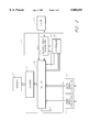
- FIG. 2 schematically shows one preferred embodiment of the present invention.
- FIG. 2 is a schematic block diagram of one preferred embodiment according to the present invention.
- the present monitor-controlling device 5 with a bi-directional interface includes a buffer 51, a decoder 52, a controlling circuit 53 and a bi-directional transmitter 54.
- the monitor-controlling device 5 further includes a timer signal generator 3 and a clock signal generator 4.
- the decoder 52 is electrically connected to the monitor 1. Taking the telephone device for example, the buffer 51 is electrically connected to the dialer 2 of the telephone device, the timer signal generator 3 and the clock signal generator 4. The data code and the control code from the dialer 2 are transmitted into the buffer 51 by way of the bi-directional transmitter 54. According to said control code, the controlling circuit 53 decides whether the bi-directional transmitter 54 provides the buffer 51 with a feedback path f.p. to transmit the data back to the dialer 54.
- the operation of the present invention can be outlined as follows: (1) uni-directional transmission operation and (2) bi-directional transmission operation.
- the controlling circuit 53 allows the buffer 51 to transmit the data to the decoder 52.
- the data in the buffer 51 includes the name data and the number data from the dialer 2, the timer data from the timer signal generator 3, and the clock data from the clock signal generator 4.
- the controlling circuit 53 can decide which kind of data to be sent to the decoder 52. After being decoded by the decoder 52, the data can be shown on the monitor 1.
- the controlling circuit 53 is in the bi-directional transmission operation in response to the control code and therefore allows the bi-directional transmitter 54 to turn on the feedback path f.p.
- the data in the buffer 51 can be transmitted back to the dialer 2 and thus be used by other external circuits.
- the buffer 51 can be implemented by a shift register.
- the clock signal for the shift register 51 is from the circuit outside the monitor-controlling device 5, e.g., the clock CLK from the dialer 2. After every clock, a one-bit data code is transmitted to the shift register 51.
- a monitor-controlling device with a bi-directional interface, used for a system having a monitor, has the following advantages:
- the data in the shift register can also be used by other external circuits.
- the present monitor-controlling device can be more flexible in various applications.
- the clock signal for the shift register is provided by the circuit outside the monitor-controlling device 5, so we don't need any synchronous circuit. The manufacturing cost is therefore decreased.
- the shift register only needs two wires to transmit the data to the external circuits, so the wide bus is spared and the resulting circuits are more stable and less complicated.
- the LCD monitor or the LED monitor is suitable.
- the present invention can be used in the dialer or micro processor of a communication system. Morever, it can be solely used in the application which requires diaplaying the time, the name, etc.
- the present invention is suitable for the Caller ID system of the telephone and telegraph office.
Abstract
Description
Claims (20)
Priority Applications (1)
| Application Number | Priority Date | Filing Date | Title |
|---|---|---|---|
| US08/677,107 US5805693A (en) | 1996-07-09 | 1996-07-09 | Monitor-controlling device |
Applications Claiming Priority (1)
| Application Number | Priority Date | Filing Date | Title |
|---|---|---|---|
| US08/677,107 US5805693A (en) | 1996-07-09 | 1996-07-09 | Monitor-controlling device |
Publications (1)
| Publication Number | Publication Date |
|---|---|
| US5805693A true US5805693A (en) | 1998-09-08 |
Family
ID=24717357
Family Applications (1)
| Application Number | Title | Priority Date | Filing Date |
|---|---|---|---|
| US08/677,107 Expired - Fee Related US5805693A (en) | 1996-07-09 | 1996-07-09 | Monitor-controlling device |
Country Status (1)
| Country | Link |
|---|---|
| US (1) | US5805693A (en) |
Cited By (4)
| Publication number | Priority date | Publication date | Assignee | Title |
|---|---|---|---|---|
| US5917364A (en) * | 1996-12-25 | 1999-06-29 | Nec Corporation | Bi-directional interface circuit of reduced signal alteration |
| US20060001632A1 (en) * | 2004-06-30 | 2006-01-05 | Fujitsu Display Technologies Corporation | Control device for display panel and display apparatus having same |
| US20150079908A1 (en) * | 2012-05-31 | 2015-03-19 | Koninklijke Philips N.V. | Measurement device |
| US11040350B2 (en) | 2016-07-18 | 2021-06-22 | Siemens Healthcare Diagnostics Inc. | Liquid analytical reagent dispensing apparatus and analytical kits and methods of use related thereto |
Citations (3)
| Publication number | Priority date | Publication date | Assignee | Title |
|---|---|---|---|---|
| US4585904A (en) * | 1982-02-05 | 1986-04-29 | General Telephone Inc. | Programmable computerized telephone call cost metering device |
| US4625276A (en) * | 1983-08-31 | 1986-11-25 | Vericard Corporation | Data logging and transfer system using portable and resident units |
| US5541640A (en) * | 1992-06-23 | 1996-07-30 | Larson; Craig R. | Videophone for simultaneous audio and video communication via a standard telephone line |
-
1996
- 1996-07-09 US US08/677,107 patent/US5805693A/en not_active Expired - Fee Related
Patent Citations (3)
| Publication number | Priority date | Publication date | Assignee | Title |
|---|---|---|---|---|
| US4585904A (en) * | 1982-02-05 | 1986-04-29 | General Telephone Inc. | Programmable computerized telephone call cost metering device |
| US4625276A (en) * | 1983-08-31 | 1986-11-25 | Vericard Corporation | Data logging and transfer system using portable and resident units |
| US5541640A (en) * | 1992-06-23 | 1996-07-30 | Larson; Craig R. | Videophone for simultaneous audio and video communication via a standard telephone line |
Cited By (6)
| Publication number | Priority date | Publication date | Assignee | Title |
|---|---|---|---|---|
| US5917364A (en) * | 1996-12-25 | 1999-06-29 | Nec Corporation | Bi-directional interface circuit of reduced signal alteration |
| US20060001632A1 (en) * | 2004-06-30 | 2006-01-05 | Fujitsu Display Technologies Corporation | Control device for display panel and display apparatus having same |
| US7969427B2 (en) | 2004-06-30 | 2011-06-28 | Fujitsu Limited | Control device for display panel and display apparatus having same |
| US20150079908A1 (en) * | 2012-05-31 | 2015-03-19 | Koninklijke Philips N.V. | Measurement device |
| US9769868B2 (en) * | 2012-05-31 | 2017-09-19 | Koninklijke Philips N.V. | Measurement device |
| US11040350B2 (en) | 2016-07-18 | 2021-06-22 | Siemens Healthcare Diagnostics Inc. | Liquid analytical reagent dispensing apparatus and analytical kits and methods of use related thereto |
Similar Documents
| Publication | Publication Date | Title |
|---|---|---|
| US7146193B2 (en) | Portable telephone set and window switching control method | |
| KR960006642A (en) | Enhanced Peripherals for Use in Multimedia Conferencing Systems | |
| KR960039723A (en) | Portable phones and display adapters | |
| EP1242896A1 (en) | Virtual device architecture for mobile telephones | |
| US5805693A (en) | Monitor-controlling device | |
| JPH0865357A (en) | Pc card radio modem | |
| KR100202142B1 (en) | Telephone having separating ketpad & the operating method | |
| KR20010015033A (en) | A system having a port with two operating modes | |
| KR100605804B1 (en) | A display chracter font tranfering apparatus and method of portable terminal equipment | |
| EP0667599B1 (en) | Selective calling receiver for computing devices | |
| US5825859A (en) | Display control device allowing information transmission to both display and dialer | |
| KR0165197B1 (en) | Personal digital assistant | |
| EP1318652B1 (en) | Identification of code transmissions sent by an accessory device to a mobile terminal depending on a previous code value | |
| KR940004387B1 (en) | Apparatus for controlling communication between ic card and host computer | |
| CN219304829U (en) | Electronic equipment | |
| JPS615654A (en) | Initial setting system of digital line terminator | |
| US20060142046A1 (en) | Interactive system associated with electronic equipment | |
| KR100539897B1 (en) | How to display time information of mobile communication terminal | |
| KR100587287B1 (en) | Method for Selecting communicating Mode in Video Communication Terminal | |
| KR20090013345A (en) | Dual processor type mobile communication terminal and method for processing usb connection thereof | |
| KR0154460B1 (en) | Method of display of extension number of other busy keyphone | |
| CN1088881C (en) | Displaying device control apparatus with double direction interface | |
| KR0176391B1 (en) | Speed junction method between digital communication device and terminal device | |
| KR19980015321A (en) | How to control the calendar note and notification function of the keyphone system | |
| KR100200836B1 (en) | Communication device having radio paging function and interface method thereof |
Legal Events
| Date | Code | Title | Description |
|---|---|---|---|
| AS | Assignment |
Owner name: HOLTEK MICROELECTRONICS INC., TAIWAN Free format text: ASSIGNMENT OF ASSIGNORS INTEREST;ASSIGNORS:CHANG, CHERN-JSAIR;WU, RONG-TYAN;REEL/FRAME:008116/0248 Effective date: 19960621 |
|
| AS | Assignment |
Owner name: UTEK SEMICONDUCTOR CORP., TAIWAN Free format text: CHANGE OF NAME;ASSIGNOR:HOLTEK MICROELECTRONICS, INC.;REEL/FRAME:009490/0001 Effective date: 19980630 |
|
| AS | Assignment |
Owner name: HOLTEK SEMICONDUCTOR,INC., CHINA Free format text: ASSIGNMENT OF ASSIGNORS INTEREST;ASSIGNOR:UTEK SEMICONDUCTOR CORPORATION;REEL/FRAME:009845/0164 Effective date: 19990210 |
|
| FEPP | Fee payment procedure |
Free format text: PAT HOLDER CLAIMS SMALL ENTITY STATUS, ENTITY STATUS SET TO SMALL (ORIGINAL EVENT CODE: LTOS); ENTITY STATUS OF PATENT OWNER: SMALL ENTITY |
|
| FPAY | Fee payment |
Year of fee payment: 4 |
|
| FPAY | Fee payment |
Year of fee payment: 8 |
|
| REMI | Maintenance fee reminder mailed | ||
| LAPS | Lapse for failure to pay maintenance fees | ||
| LAPS | Lapse for failure to pay maintenance fees |
Free format text: PATENT EXPIRED FOR FAILURE TO PAY MAINTENANCE FEES (ORIGINAL EVENT CODE: EXP.); ENTITY STATUS OF PATENT OWNER: SMALL ENTITY |
|
| STCH | Information on status: patent discontinuation |
Free format text: PATENT EXPIRED DUE TO NONPAYMENT OF MAINTENANCE FEES UNDER 37 CFR 1.362 |
|
| FP | Lapsed due to failure to pay maintenance fee |
Effective date: 20100908 |