US5797673A - Emergency lighting unit/exit sign combination - Google Patents
Emergency lighting unit/exit sign combination Download PDFInfo
- Publication number
- US5797673A US5797673A US08/561,956 US56195695A US5797673A US 5797673 A US5797673 A US 5797673A US 56195695 A US56195695 A US 56195695A US 5797673 A US5797673 A US 5797673A
- Authority
- US
- United States
- Prior art keywords
- housing
- combination
- emergency lighting
- lighting unit
- sign
- Prior art date
- Legal status (The legal status is an assumption and is not a legal conclusion. Google has not performed a legal analysis and makes no representation as to the accuracy of the status listed.)
- Expired - Lifetime
Links
Images


Classifications
-
- G—PHYSICS
- G09—EDUCATION; CRYPTOGRAPHY; DISPLAY; ADVERTISING; SEALS
- G09F—DISPLAYING; ADVERTISING; SIGNS; LABELS OR NAME-PLATES; SEALS
- G09F13/00—Illuminated signs; Luminous advertising
- G09F13/04—Signs, boards or panels, illuminated from behind the insignia
-
- G—PHYSICS
- G08—SIGNALLING
- G08B—SIGNALLING OR CALLING SYSTEMS; ORDER TELEGRAPHS; ALARM SYSTEMS
- G08B7/00—Signalling systems according to more than one of groups G08B3/00 - G08B6/00; Personal calling systems according to more than one of groups G08B3/00 - G08B6/00
- G08B7/06—Signalling systems according to more than one of groups G08B3/00 - G08B6/00; Personal calling systems according to more than one of groups G08B3/00 - G08B6/00 using electric transmission, e.g. involving audible and visible signalling through the use of sound and light sources
- G08B7/062—Signalling systems according to more than one of groups G08B3/00 - G08B6/00; Personal calling systems according to more than one of groups G08B3/00 - G08B6/00 using electric transmission, e.g. involving audible and visible signalling through the use of sound and light sources indicating emergency exits
-
- G—PHYSICS
- G09—EDUCATION; CRYPTOGRAPHY; DISPLAY; ADVERTISING; SEALS
- G09F—DISPLAYING; ADVERTISING; SIGNS; LABELS OR NAME-PLATES; SEALS
- G09F13/00—Illuminated signs; Luminous advertising
-
- G—PHYSICS
- G09—EDUCATION; CRYPTOGRAPHY; DISPLAY; ADVERTISING; SEALS
- G09F—DISPLAYING; ADVERTISING; SIGNS; LABELS OR NAME-PLATES; SEALS
- G09F13/00—Illuminated signs; Luminous advertising
- G09F13/04—Signs, boards or panels, illuminated from behind the insignia
- G09F13/0418—Constructional details
- G09F13/0454—Slidable panels or parts
-
- G—PHYSICS
- G09—EDUCATION; CRYPTOGRAPHY; DISPLAY; ADVERTISING; SEALS
- G09F—DISPLAYING; ADVERTISING; SIGNS; LABELS OR NAME-PLATES; SEALS
- G09F13/00—Illuminated signs; Luminous advertising
- G09F13/04—Signs, boards or panels, illuminated from behind the insignia
- G09F13/0418—Constructional details
- G09F2013/05—Constructional details indicating exit way or orientation
-
- Y—GENERAL TAGGING OF NEW TECHNOLOGICAL DEVELOPMENTS; GENERAL TAGGING OF CROSS-SECTIONAL TECHNOLOGIES SPANNING OVER SEVERAL SECTIONS OF THE IPC; TECHNICAL SUBJECTS COVERED BY FORMER USPC CROSS-REFERENCE ART COLLECTIONS [XRACs] AND DIGESTS
- Y10—TECHNICAL SUBJECTS COVERED BY FORMER USPC
- Y10S—TECHNICAL SUBJECTS COVERED BY FORMER USPC CROSS-REFERENCE ART COLLECTIONS [XRACs] AND DIGESTS
- Y10S362/00—Illumination
- Y10S362/812—Signs
Definitions
- the invention relates generally to emergency lighting fixtures including illuminated signs and emergency lighting units and particularly relates to combinations of illuminated exit signs and the like with emergency lighting units to form fixtures having multiple emergency lighting functions in a single device.
- Emergency lighting capability is mandated by building codes throughout most of the world for commercial buildings in particular.
- the most common type of emergency lighting is the exit sign which is also the most noticed due not only to its ubiquity but also due to the fact that most exit signs are constantly illuminated and are therefore readily seen. Exit signs are typically placed above doorways or in egress paths to indicate in a time of emergency the most efficient manner of exiting a building.
- Another common form of emergency lighting is generally referred to as an emergency lighting unit and typically operates two spaced lamps which are often referred to as "frog eyes”.
- Emergency lighting units operate only in the event of emergency and are intended to supply an acceptable degree of ambient illumination under emergency conditions, these conditions usually including loss of normal power.
- An emergency lighting unit includes a battery and sensing circuitry which initiates operation of the battery on loss of normal building power, the lamps of the emergency lighting unit being then activated to provide emergency lighting.
- exit/unit combo a "combination" exit sign and emergency lighting unit, this type of fixture being commonly referred to as an exit/unit combo.
- the "combo” has previously taken the form of an emergency lighting unit mounted to an exit sign, the emergency lighting unit most often being mounted along the top of the exit sign.
- the exit sign and the emergency unit operate separately although certain functions can be shared between the exit sign and the unit by providing common circuitry such as would be useful to detect power line failure for switching the exit sign to DC battery power and for initiating operation of the emergency lighting unit.
- a particular exit/unit combo which has enjoyed substantial market acceptance is the QUANTUM Exit/Unit Combo manufactured by Lithonia Lighting, Inc.
- the Lithonia combo manufactured and marketed under the QUANTUM mark is comprised of a substantially all-plastic exit sign and a substantially all-plastic emergency lighting unit, thereby resulting in a combo product which is light in weight relative to previous combo products many of which included metal housings and parts which caused the products to be heavy and therefore more difficult to support especially in end mounted installations.
- the Lithonia QUANTUM combo could be rapidly and easily mounted at the top, back or ends with adequate support of the assembly being possible even when end mounted. Manufacture and maintenance of the Lithonia combo were facilitated by the virtual all-plastic structure of the Lithonia product which allows at least portions of the product to be positively and readily snap-fitted to each other.
- the structure of the present exit/unit combo allows support of battery loads in tension rather than through the usual cantilevered support of loads disposed internally of a sign housing.
- the structure of the present combo housing provides support of such efficiency as to prevent warping or bowing of the housing over time, thereby providing substantially improved product quality along with substantially improved product appearance.
- the exit/unit combo of the invention is provided with significant structural features useful not only with the combo but also with exit signs per se and with emergency lighting units per se as well as remote emergency lighting units.
- the present invention thus provides substantial improvement over the prior art by the provision of an integral and integrated exit/unit combo characterized by ease of assembly, installation and maintenance as well as by extraordinarily acceptable appearance.
- the invention provides an emergency lighting fixture which combines the functions of an illuminated sign, particularly an exit sign, with an emergency lighting unit, the structural combination being integrated into a single housing which internally contains those structural elements necessary to produce the functions of the feature and which carries emergency lamping externally of the housing at multiple locations thereby providing extraordinary flexibility in use.
- the present combination of an exit sign and an emergency lighting unit or "exit/unit combo" is preferably formed of a polymeric material such as polycarbonate/ABS, thereby allowing molding of a fixture housing with most of the structural elements necessary to produce the functions of the fixture being integrally formed with the housing, these molded structural elements and other structure contained within the housing being located in the housing in a manner whereby the elements combine to produce synergistic effects in addition to the primary functions of the structural elements, the fixture being totally integrated as to structure and function as well as being substantially integral in construction.
- a polymeric material such as polycarbonate/ABS
- Formation of the fixture essentially from moldable material further allows integral formation of snap-fitting structural elements which not only provide easy snap fitting of facing plates to the housing to form the primary structural portion of the combo per se but also the integral formation of snap-fitting structure with bulb holders, battery mounting elements and option board storage elements inter alia. Assembly of the fixture is therefore facilitated at least in part due to the reduced number of individual parts occasioned by the integral nature of the housing inter alia.
- the housing of the present exit/unit combo fixture is configured to support battery weights inter alia which are typically greater than those battery weights encountered in conventional exit signs due to the need to operate exit lighting, unit lighting and even remote unit lighting with a single battery disposed within the housing.
- the battery is centered with the housing disposed at a lower portion thereof, battery location couples with a central, vertical structural beam known as a "ladder" allows support of the battery inter alia in tension rather than in a cantilevered arrangement as has been previously employed in exit signs and the like.
- the structural features such as the ladder integrated with location of major weighting such as the weight of the battery actually allows use of a material such as plastic for formation of the fixture, the self-support provided by the structure itself preventing warping and bowing of the plastic exit/unit combo fixture over time such as would occur with a fixture having the weight of the exit/unit combo fixture if not provided with the integrated structural relationships of the invention.
- the dimensional stability of the present exit/unit combo fixture occurs due to the structural features of the fixture which maintain substantial portions of the fixture weight in tension.
- the exit/unit combo fixture of the invention provides "unit" emergency lighting by the disposition of one or more emergency lamps mountable at different locations on the periphery of the fixture housing to accommodate differing lighting situations.
- the lamps are mounted by lamp holders fitted with swiveling concentric spherical structural elements which allow movement of the lamps with a degree of freedom not previously possible, the structure of the concentric spherical elements additionally yielding a compact profile which is not only attractive in appearance but functional due to the volumetric efficiency thus provided.
- the lamp holders of the invention are formed with torsion snap elements which fit into slots formed in peripheral edges of the housing, the slots receiving the snap elements of the lamp holders to positively mount the lamp holders in desired locations on the fixture.
- the particular snap element/slot arrangement of the invention allows rapid and ready mounting and dismounting of the lamp holders to and from the fixture housing with positive locking of the lamp holders to the housing once assembled.
- the lamp holders of the invention can be removed from the present fixture and mounted to remote slave mounting stations driven by the fixture with the snap elements of the lamp holder fitting into arranged slots of the slave station. Further, the lamp holder can be mounted to a station separate from the fixture with battery or other operation, the lamp holder being mounted to the station through use of the snap elements of the lamp holder in cooperation with slots formed in the station.
- Various other features of the invention include structure for minimizing the "shadow" of the battery appearing through face plates of the exit/unit combo fixture; registration structure for mounting of a diffusion panel in a face plate of the fixtures; routing of wiring in association with the ladder support and in front of the battery with the use of slack in the wiring and structure for compartmentalization of electrical components within the interior of the fixture housing including snap-mounting of a capacitor inter alia.
- inventive features disclosed herein are useful in fixtures other than exit/unit combo fixtures and are disclosed for use in that variety of fixtures for which these features find utility. Use of these features is thus not limited to use in an exit/unit combo fixture.
- an object of the invention to provide an integral exit/unit combo fixture having the capabilities of an exit sign and of an emergency lighting unit integrated into a fixture formed with a single housing for containing a substantial portion of the structures and for mounting emergency unit lamps on the housing externally thereof and at repositionally distinct locations of the housing.
- FIG. 1 is a perspective view of a first embodiment of the invention
- FIG. 2 is a side elevational view of the embodiment of the invention shown in FIG. 1;
- FIG. 3 is a perspective view of a second embodiment of the invention.
- FIG. 4 is a side elevational view of the embodiment of FIG. 3;
- FIG. 5 is a front elevational view of a third embodiment of the invention.
- FIG. 6 is a front elevational view of a fourth embodiment of the invention.
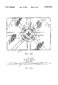
- FIG. 7 is a front elevational view of a fifth embodiment of the invention.
- FIG. 8 is a plan view of the embodiment of FIG. 3;
- FIG. 9 is a view of the housing of the invention.
- FIGS. 10A and 10B are a view of the back plate of the invention intended for wall mounting of the fixtures;
- FIG. 11A is a front elevational view of the frame of the invention.
- FIG. 11B is an elevational view taken from the rear of the frame of the invention.
- FIG. 12 is a front elevational view of the invention partially in schematic illustrating an incandescent embodiment of the invention.
- FIG. 13 is a front elevational view partially in schematic illustrating an LED/incandescent embodiment of the invention.
- FIG. 14 is a perspective view of the invention illustrating remote location of a slave fixture according to the invention.
- FIG. 15 is a perspective view of a fixture having a portion of the combination fixture forming a part thereof;
- FIG. 16 is a perspective view illustrating the structure of FIG. 15 in an assembled relationship
- FIGS. 17A-E are elevational views of the frame of the invention.
- FIG. 18 is a view of the ladder structure
- FIGS. 19A and 19B are a detailed views of the battery compartment having a relatively small lead-acid battery mounted therein;
- FIGS. 20A and 20B are detailed views of the battery compartment having a relatively larger lead-acid battery mounted therein;
- FIGS. 21A and 21B are elevational views of a DC lamp mounting arrangement
- FIGS. 22A and 22B are detailed views of the electrical compartment of the housing
- FIG. 23 is a detailed view of an option storage compartment formed in the housing
- FIG. 24 is an assembly view of components comprising the repositionable emergency lighting unit lamp assembly
- FIGS. 25A-25C are views of the apparatus of FIG. 24;
- FIGS. 26A-26C are views of the apparatus of FIG. 24;
- FIGS. 27A-27C are views illustrating operation of the torsion snaps of the invention.
- FIG. 28 is a simplified diagram of the circuitry of the invention.
- FIG. 29 is a view of a front plate and diffusion panel arrangement of the invention.
- a combination exit sign/emergency unit fixture is seen at 10 to be comprised of a housing 12 and two emergency lighting unit lamp assemblies 13.
- the fixture 10 will generally be referred to herein as the combo fixture 10 or merely as the fixture 10.
- the housing 12 is essentially formed from frame 14 and face plate 16 as well as back plate 18.
- the back plate 18 can be essentially identical to the face plate 16, such a combo fixture 10 within constituting a double-faced fixture having indicia 20 on both faces thereof such as can occur in top and end mounted installations. In a direct wall-mounted installation, the back plate 18 is necessary in order for the combo fixture 10 to be mounted directly to a wall as will be described hereinafter.
- the combo fixture 10 is typically provided with one or more directional indicators 22 which are often referred to as "chevrons", the indicators 22 preferably comprising snap-fitting chevron structures which can be rapidly and positively mounted into openings 23 formed on the face plate 16 without the requirement for gaining access into the interior of the housing 12. While various chevron structures can be utilized, a particularly suitable structure is disclosed in U.S. patent application Ser. No. 08/327,487, filed Oct. 21, 1994, by Stephen T. Smith with the title "Direction Indicator Covers for Emergency Lighting System", the patent application being assigned to the assignee of the present patent application, the disclosure of Ser. No. 08/327,487 being incorporated hereinto by reference.
- At least one of the indicators 22 is mated into the corresponding opening 23 to prevent light generated interiorly of the housing 12 from passing through the opening 23.
- the combo fixture 10 may be placed directly over a doorway or the like, it is possible that both of the indicators 22 will be placed in the corresponding openings 23.
- Certain other installations may require that neither of the directional indicators 22 be mounted in the corresponding openings 23, such an installation signalling that a path of egress may exist to both sides of the combo fixture 10.
- a pair of incandescent lamps 24 are disposed within the interior of the housing 12 and operate on AC line voltage to illuminate the combo fixture 10 during normal, non-emergency situations during which the location of emergency egress paths is to be recognized by those persons using the environmental spaces within which the fixture 10 is mounted.
- a pair of emergency lamps 26 such as are seen in FIG. 9 are located internally of the housing 12 and powered only during loss of AC line voltage by means of a battery 30 (as seen in FIG. 9 inter alia), appropriate circuitry (not shown in FIGS. 1 and 2) causing DC voltage from the battery 30 to operate the emergency lamps 26 during a power failure such as would occur during emergency situations.
- the non-emergency lamps 24 thus illuminate the indicia 20 in normal situations with the emergency lamps 26 illuminating the indicia 20 during emergency situations. While the combo fixture 10 intends the indicia 20 to take the form of the word "EXIT" formed in the face plate 16, it is to be understood that other indicia could be formed in the face plate 16 such as is conventional in the art.
- the use of non-emergency lamps such as the lamps 24 and driven by alternating current from building mains as well as the use of emergency lamps such as the lamps 26 operated on DC battery current in the event of power loss and/or emergency conditions is known in the art and need not be described in greater detail herein. As will be described hereinafter relative to FIG. 13, it is to be seen that a light emitting diode array 28 can be utilized in non-emergency situations as replacement for the lamps 24.
- a canopy 32 is employed to mount the combo fixture 10 to a J-box (not shown) so that the fixture 10 is positively mounted either to the ceiling or to a wall of an environmental space within which the fixture 10 operates.
- openings 34 are provided in the frame 14 at least centrally of an upper edge of the housing 12. Openings 34 can similarly be provided on side edges of the housing 12 for end mounting of the fixture 10 such as can occur with the structure of FIGS. 6 and 7, that is, when one of the ends of the fixture 10 is available for end mounting.
- the combo fixture 10 be mounted either from the top or from the back as will be described in detail hereinafter and as is particularly shown relative to a top mount in FIGS. 1 and 2 inter alia. While various canopy structures can be utilized including a number of canopies which are conventional in the art, it is preferred to use the canopy described in co-pending U.S. patent application Ser. No. 08/343,775, filed Nov. 22, 1994, by Gary S. Andre, Andrew E. Masters and Stephen P. Smith and entitled “Emergency Lighting Connections", Ser. No. 08/343,775 being assigned to the assignee of the present application.
- While the canopy 32 and corresponding structure such as the openings 34 in the frame 14 inter alia which are present in the combo fixture 10 can be identical to that corresponding structure disclosed in co-pending patent application Ser. No. 08/327,487, it is to be understood that the canopy of the co-pending application for patent is only one of a number of canopy structures usable to fasten the combo fixture 10 to a J-box (not shown). In essence, mounting of the canopy 32 or any other canopy to such a J-box (not shown) is conventional in the art and further discussion of same is not believed necessary to an understanding of the present disclosure.
- the present invention provides a dimensionally stable combo unit 10 which does not warp or bow over time even though effectively formed completely of "plastic", the combo fixture 10 being the first and only combo fixture formed of plastic wherein all batteries and other structural features are effectively contained and/or supported by a single housing such as the housing 12.
- the combo fixture 10 could be formed of a material such as sheet metal, it is to be understood that a number of the advantages of the invention would be lost if the combo fixture 10 is so formed.
- the combo fixture 10 can be assembled from a relatively small number of individual parts especially since the frame 14 as will be more fully described hereinafter can be molded from a plastic material to produce a single part having a very large number of structural features integrally formed therewith.
- All structural features of the combo fixture 10 are formed of plastic and are molded. Certain parts such as the lamps 24 and 26 and the battery 30, for example, are not formed of plastic but are items which must be otherwise formed. However, these parts are not structural and have no function in support of the overall weight coupled with maintenance of the integrity of the combo fixture 10 per se.
- the function of the housing 12 as a single containing unit is further improved by the ability to snap-fit together virtually every combination of parts comprising the combo fixture 10.
- Formation of the combo fixture 10 substantially from plastic materials facilitates not only the essentially integral nature of the fixture 10 with fewer parts but also facilitates the snap-fitting together of the relatively few parts comprising the fixture 10.
- the essentially all-plastic single housing 12 is constructed as will be described hereinafter such that fixture weight can be supported without resort to metal structural features such as would be occasioned by battery weight inter alia in a combination exit sign/emergency unit fixture.
- the structural strength of the present combo fixture 10 is provided even though the housing 12 is only slightly larger than the housings of most conventional exit signs.
- a further general feature of the combo fixture 10 is occasioned by the cooperative relationship between the emergency lighting unit lamp assemblies 13 and the frame 14 of the housing 12.
- the assemblies 13 can be positioned on each end of the housing 12 as is seen in FIGS. 1 and 2.
- the assemblies 13 can be otherwise mounted to the housing 12 such as is seen in FIGS. 5 and 7 by the simple provision of a pattern of slots (not shown in these figures) so that the assemblies 13 can be mounted to one side and to the top as seen in FIG. 5 or with two assemblies on top as seen in FIG. 7.
- slots can be formed in lower surfaces of the housing 12 so that one or more of the assemblies 13 could be mounted along the lower edge of the housing 12. As is seen in FIG.
- a dual unit lamp assembly 36 is mounted along the top edge of the housing 12 utilizing the same slot pattern as would be used with the structure shown in FIG. 7.
- the structure preferred for mounting of the assemblies 13 and the assembly 36 will be described in detail hereinafter. Appreciation of the structure of the assemblies 13 and of the assembly 36 is necessary in order to understand the importance of the fact that said assemblies 13 and 36 can be repositioned on the housing 12 or removed entirely to constitute slave and/or remote units for producing lighting at locations distant from the combo fixture 10.
- FIGS. 3, 4 and 8 in particular illustrates a further capability of the invention, double-sided dual unit lamp assemblies 38 being substituted for the assemblies 13 so that the unit emergency lighting function can be provided relative to both faces of the housing 12. Due to the low-profile space-saving nature of the structure of the assemblies 13, it is a simple matter to form the double-sided dual unit lamp assembly 38 without substantial modification, this structure being best understood by subsequent description of the assemblies 13 inter alia.
- either of the assemblies 13 and 38 can be removed from the housing 12 and attached to a mounting base 40 and driven as a remote slave unit from power provided by the battery 30 within the housing 12.
- a battery (not shown) within the mounting base 40 could provide power for a totally separate fixture as shown in FIGS. 14, 15 and 16.
- the dual unit lamp assembly 36 of FIG. 6 as previously described could also be removed from the housing 12 of FIG. 6 and provided with a mounting base (not shown) of a greater lengthwise dimension than said base 40 and provided with a slot pattern capable of mounting said assembly 36 for use as a remote slave unit or as a remote, self-contained unit.
- FIG. 15 illustrates the pattern of slots 42 useful for mounting of the assemblies 13 and 38 to the mounting base 40 in a manner such as will be described in detail hereinafter.
- the housing 12 essentially comprises a container formed by the frame 14, the face plate 16 and the back plate 18.
- the back plate 18 is replaced by a plate which would be essentially identical to the face plate 16.
- the back plate 18 is used to enclose the housing 12 in those situations wherein the visible indicia 20 is only required on the "front" of the housing 12 and is provided by the face plate 16.
- the back plate 18 is particularly used in situations wherein the combo fixture 10 is installed directly against a J-box (not shown) mounted flushly in a vertical wall (not shown), the back plate 18 being then mounted directly to such a J-box (not shown) through use of conventional connections with the back plate 18 connecting to the frame 14 as will be described hereinafter.
- the face plate 16 and the back plate 18 each connect to the frame 14 by means of four snap-fitting connections 44 which comprise two spaced slots 46 formed along top and bottom edges of each of the plates 16, 18, each plate 16, 18 thus having a total of four slots 46 intended to facilitate connection of the plates 16, 18 to the frame 14.
- the frame 14 is provided with a total of eight mounting tabs 48 with two each of said tabs 48 being disposed along each side of both of the top and bottom edges of the frame 14, the tabs 48 being positioned to be received one each within each of the slots 46 formed in the plate 16, 18 so that the plate 16, 18 can be readily and rapidly assembled to the frame 14 to enclose the housing 12 as is best seen in FIGS. 17D and 17E.
- the combo fixture 10 Essentially all of the features of the combo fixture 10, with the exception of the lamp assemblies 13 or similar structure, are contained within the housing 12 and are supported by the frame 14.
- the lamp assemblies 13 are in essence also carried by the housing 12 but on exterior portions thereof.
- the weight of the combo fixture 10 due both to that structure located interiorly and exteriorly of said housing 12 is effectively supported in tension rather than by cantilever as is conventional in the prior art.
- the housing 12 and particularly the frame 14 is thus engineered in a manner particularly intended to support the weight of the fixture 10 in tension, thereby allowing the formation of the fixture 10 and particularly of the frame 14 essentially entirely of a "plastic" material such as polycarbonate/ABS.
- This ability to form the fixture 10 and particularly the frame 14 from plastic material then further allows the frame 14 to be molded integrally to thereby reduce the number of parts which must be formed and then assembled to produce the combo fixture 10.
- the construction and structure of the frame 14 as a single molded piece still further allows the carriage of heavy parts such as the battery 30 inter alia internally of the housing 12 and within the single housing 12.
- Formation of the combo fixture 10 and especially the integral frame 14 from a plastic material further facilitates the snap-together construction of the combo fixture 10, virtually all parts of the fixture 10 being snap-fitted together thereby yielding a total structure which can be readily and rapidly assembled.
- FIG. 17A illustrates the one-piece frame 14 without mounting of other portions of the fixture 10 thereto.
- FIGS. 17B through 17E illustrate the frame 14 with the plates 16, 18 mounted thereto as illustration of the enclosed housing 12.
- the frame 14 is seen to be provided on each end with a pattern of four slots 50 which are of a size and which are spaced apart in a rectangular form in the manner of the slots 42 discussed above relative to the mounting of one of the lamp assemblies 13 to the mounting base 40 to form a remote fixture.
- the top of the frame 14 is provided with two of the patterns of four slots 50.
- the slots 50 are formed in the frame 14; however, portions of the periphery of the plates 16, 18 face the slots 50 on assembly of said plates 16, 18 to the frame 14 and to render less conspicuous the slots 50 into which torsion snaps 52 are inserted to mount the lamp assemblies 13 (as well as the lamp assembly 36 to the top of the housing 12) to the housing 12. While not shown in FIG.
- a pattern of the slots 50 could be formed along the bottom of the housing 12 if mounting of one or more of the lamp assemblies 13 to the bottom of the housing 12 is desired. Mounting of one or more of the lamp assemblies 13 to the bottom of the housing 12 would be advantageous in situations where flexibility of operation is desirable within the space within which the combo fixture 10 is utilized.
- the frame 14 is also seen in FIG. 17E to be provided with fixed louver vent openings 54 to facilitate ventilation of the housing 12.
- a flapper switch 56 is provided in the bottom of frame 14 in association with test circuitry (not shown in FIG. 17E) to allow testing of the electrical systems of the combo fixture 10 as will be described in detail hereinafter.
- the canopy 13 referred to hereinabove can be used to mount the combo fixture 10 as will be described hereinafter and as is described in co-pending U.S. patent application Ser. No. 08/343,775, filed Nov. 22, 1994 as aforesaid, the disclosure of this application for patent being incorporated hereinto by reference.
- FIG. 17A wherein upper and lower walls 58 and 60 are integrally formed with side walls 62 and 64, said walls defining the periphery of the frame 14 and thus of the housing 12.
- An upper interior wall 66 extends parallel to the upper wall 58 and terminates at respective ends in corner plates 68 and 70, the plates 68 and 70 each having side-mounted upper and lower angled elements 72 and 74 which have open-ended slots 76 which are capable of receiving wiring (not shown in FIG. 17A) for holding said wiring in place within the interior of the housing 12.
- the plates 68 and 70 respectively define spaces 78, 80 within which wiring, wire nuts, plugs and the like (not shown) can be disposed.
- the plates 68, 70 along with the angled elements 72 and 74 provide strengthening of the frame 14 even in the absence of the interior wall 66. Coupling of the interior wall 66 with the plates 68, 70 and angled elements 72, 74, respectively, and further with interior side walls 82 and 84 provides a high degree of stiffness and rigidity to the frame 14.
- the side walls 82 and 84 connect at respective ends to a lateral platform 86 comprised or horizontally disposed side tables 88 and 90 which connect to a central mounting angle 92 which is surmounted by central support webs 94 and 96 which further connect to side webs 96 and 98 respectively through upper vertical walls 100 and 102.
- the side webs 96 and 96 respectively connect to end webs 104 and 106 through triangular normally related supports 108 and 110, the end webs 104 and 106 respectively connecting to lowermost ends of the side walls 82 and 84, thereby providing a continual interior structural web which is centrally bisected by a vertical ladder 112 formed of spaced vertical stiles 114 having horizontal rungs 116 regularly disposed along the stiles 114. Openings between the rungs can be utilized for management of wiring within the interior of the housing 12 and particularly relative to options available with the combo fixture 10.
- the support webs 94 bend 90° to form ladder connection walls 118 which join to respective ends of the stiles 114.
- a bottom ladder plate 120 completes connection of the stiles 114, the plate 120, the lower ends of the stiles 114, the walls 118, and the support webs 94 by connecting to and being integrally formed with top portions of the angle 92.
- the top end of the ladder 112 joins integrally with the upper interior wall 66 and the upper wall 58, thereby providing a tensioned support structure internally of the housing 12 which acts to support the weight of the combo fixture 10 substantially in tension rather than cantilevered as in prior exit signs and sign-like fixtures.
- the weight of the battery 30 located within battery compartment 122 is particularly seen to be mounted in tension by the ladder 112 inter alia due also in part to the placement of the battery 30 (and any other battery) centrally of the interior of the housing 12 and along the lower portion thereof.
- Interior canopy mounting housing 124 are respectively disposed centrally between the upper wall 58 and the interior wall 66 and between the side walls 62, 64 and the interior side walls 82, 84.
- Wiring guide clips 126 are disposed on either side of the uppermost mounting housing 124 to facilitate a desired location of wiring (not shown in FIG. 17A) along upper portions of the housing 12.
- Substantially conventional mounting elements 128 each releasably hold lamp bases 130 and associated non-emergency AC bulbs 132, the mounting elements 128 also being integrally formed with the frame 14.
- Mounting bases 134 capable of holding lampsockets 136 and associated DC emergency bulbs 138 are integrally formed on respective portions of the support webs 94, the location of the bulbs 138 acting to produce light at locations above the battery compartment 122 so that light can be directed about the upper portions of the battery 30 (or other battery) to reduce the shadowing effect of the battery 30 within the indicia 20 as will be described in greater detail hereinafter.
- An electronics compartment 140 is located below the side table 88 and laterally of the battery compartment 122 while an options compartment 142 is located below the side table 90 and to the other side of the battery compartment 122.
- the respective compartments 140 and 142 are separated from the battery compartment 122 by means of respective vertical walls 144 and 146.
- Clips 148 disposed on opposite sides of the interior of the housing 12 extend respectively from the corner plates 68, 70 and are adapted to hold respective LED arrays 28 (see FIG. 13) within the interior of the housing 12.
- the structures described above and which can be seen in FIG. 17A are integrally formed with the frame 14 by molding of a plastic material. In essence, the entire structure seen in FIG. 17A is a single unitary structure comprising the frame 14 and molded with said frame 14 are openings provided as a means for reducing the amount of plastic necessary for molding thereof.
- the ladder 112 is provided as an integral portion of the frame 14 to provide support in tension for the entirety of the combo fixture 10 and particularly for the battery 30 held within the battery compartment 122 (or for any other battery held within the battery compartment 122).
- the ladder 112 is advantageously located within the interior of the housing 12 to provide tension support for the weight of the fixture 10 as well as for battery weight. It should be understood, however, that the ladder 112 could take other forms, such as a solid vertical member whether or not connected permanently to the angle 92 at the lower end thereof or to the interior wall 66 and the wall 58.
- the ladder 112 is formed of the stiles 114 and of the rungs 116 in order to provide openings 115 between the rungs through which wiring can be strung for management of the location of wiring within the interior of the housing 12.
- the openings 115 are also provided for reduction of material and for facilitating light movement within the interior of the housing 12.
- the openings 115 also serve to provide access for routing wiring (not shown) within the interior of the housing 12 as will be better appreciated hereinafter
- the battery 30 is located centrally of the lower portion of the housing 12 so as to advantageously allow the ladder 112 to act in tension to support the weight of the battery 30.
- the battery 30 is intended to be a conventional rechargeable lead-acid battery, it is possible to utilize lead-acid batteries of greater capacity with weights up to approximately 4 pounds when a greater amount of power is necessary for providing for a greater period of time and for that additional power necessary to operate slave units remote from the fixture 10 such as has been described above. It is also possible to utilize nickel-cadmium batteries of smaller size, the smaller Ni-Cd battery (not shown) being mounted within the interior of the battery compartment 122, the details of mounting of the Ni-Cd battery within the compartment 122 not being described herein.
- the ladder 112 is provided with horizontal elongated tab elements 154 and 156, the elements 154 and 156 being preferably used for management of wiring (not shown) associated with the fire alarm interface 150.
- the ladder 112 is further provided with peg elements 152 disposed one each on either side of the ladder 112 and extending from each of the stiles 114 near the uppermost end of the ladder 112, the peg elements 152 acting to receive snap elements 158 and 160 located on the interior wall of the back plate 18 as will be described hereinafter, the snap elements 158 and 160 cooperating respectively with the peg elements 152 to facilitate mounting of the frame 14 to the back plate 18 when the back plate 18 is mounted directly to a J-box (not shown) mounted flushly in a wall surface.
- the battery compartment 122 is configured to house the battery 30 as well as a larger battery 162. It is to be understood, however, that only one of the batteries 30 and 162 would be utilized at any one given time.
- the battery compartment 122 is formed centrally of the lower portion of the combo fixture 10 and is provided with snap fingers 164 on inner surfaces of the walls 144 and 146, the snap fingers 164 extending from said wall surfaces at a lesser height forwardly of the compartment 122 and terminating at a greater height interiorly of the compartment 122 such that the battery 30 can slide over the snap fingers 164 and into a position of essentially against a back wall 166 of the battery compartment 122.
- the battery compartment 122 is provided with a top wall 168 having tabs 170 extending downwardly therefrom at the outermost end of said top wall 168 so that the larger battery 162 can be slipped into place under the tabs 170 and into a position abutting the back wall 166 and held by the tabs 170 in order to hold the larger battery 162 in place.
- the battery compartment 122 is provided with structure capable of holding batteries of at least two different sizes within said compartment 122 by snap-fitting arrangements.
- the batteries 30 and 162 When placed within the battery compartment 122 as is necessary for operation, the batteries 30 and 162 are of a sufficient height as to extend into the lower part of the indicia formed in the face plate 16. Due to this extension of the battery 30 and the battery 162 into the legend, it is possible that a shadowing effect is caused such that lower portions of the indicia are darker than upper portions of the indicia.
- the location of the lamps 24 within the interior of the housing 12 during normal operation and the location of the lamps 26 within the interior of the housing 12 during emergency operation provides light within the interior of the housing 12 which is reflected within said housing interior.
- This light is controlled in part by means of a reflective cover 172 attached to the top of the battery 30 (or the battery 162) with the lower edge of the reflective cover 172 extending downwardly to at least the level of the side tables 88 and 90 such that light is reflected outwardly of the lower portions of the indicia 20 on the face plate 16 to locally increase the amount of light passing through said indicia 20 at lower portions thereof.
- Provision of the reflective cover 172 thus acts to reduce the effect of the otherwise dark form of the battery 30 or the battery 162 so that the shadowing effect does not detract from the appearance and function of the indicia 20.
- At least the upper portion of the batteries 30, 162 could be painted with a white paint or coated with a reflective material in order to provide a function similar to the function of the reflective cover 172.
- the reflective cover 172 can also be utilized as a pull tab for removal of the battery 30, 162 from the battery compartment 122.
- wiring extends from the electronics compartment 140 to the options compartment 142 as is seen in FIG. 9, this wiring 174 is caused to be slack in front of the battery compartment 122 so that insertion of one of the batteries 30, 162 into the battery compartment 122 does not engage the wiring 174 and pull said wiring into the battery compartment 122.
- the bulb 138 is snapped into the lamp socket 136 to be structurally held thereby and to electrically connect with the lamp socket 136 to power provided in an emergency situation by the battery 30, 162 inter alia.
- the lamp socket 136 is formed of a rectangular collar 176 open at one end to receive the bulb 138, electrical contacts (not shown) being located within the interior of the collar 176.
- the collar 176 terminates at the end opposite the bulb 138 in a reduced lower base portion, the lamp socket 136 snap-fitting into one of the mounting bases 134.
- the lamp base 134 is formed of two basic upper elements 180 each having walls 182 which are perpendicular to each other, rear walls 182 extending toward each other but not contacting at the rear of the base 134.
- Snap tabs 184 extend from the facing walls 182 toward each other at the upper end of the base 134, the heights of the walls 182 being essentially equal to the height of the collar 176.
- a pair of lateral snaps 186 extend from the rear of the base 134 below the walls 182 and receive the lower base portion 178 therebetween when the lamp socket 136 is snap-fitted into the mounting base 134.
- the collar 176 of the lamp socket 136 is partially enclosed by the walls 182 with the snap tabs 184 abutting against upper edges of the collar 176 to prevent dislodgement of said socket 136 in an upward direction.
- the discontinuity provided by the lack of contact between the rear walls 182 thereby allows upper portions of the mounting base 134 to expand on insertion of the lamp socket 136 thereinto. Snap mounting of the lamp socket 136 to the mounting base 134 therefore occurs.
- the lateral snaps 186 prevent dislodgement of the lamp socket 136 forwardly of the mounting base 134, the snaps 186 fitting against the reduced lower base portion 178 so that the lamp socket 136 is positively retained within the mounting base 134.
- the mounting of the DC emergency lamps 26 can thus be accomplished both rapidly and easily and within a minimum of parts not integrally formed with the frame 14.
- the options compartment 142 is further defined by back wall 188 which has a plurality of openings 190 formed therein to reduce the quantity of plastic material necessary for formation of the frame 14 and to facilitate ventilation of the housing 12.
- a variable printed circuit board capturing assembly is seen to be disposed centrally of the compartment 142 at 192 to comprise spaced apart upper and lower plates 194 and 196 with each plate having an inwardly extending lip 198 formed along respective outer edges of the plates 194, 196.
- the plates 194, 196 are attached along inner edges thereof to the back wall 188 and have the capability of springing together when separated from each other by pressure.
- a printed circuitboard bearing an option such as a fire alarm interface option can be mounted between the plates 194, 196 and held by the spring function existing between said plates 194, 196.
- the lips 198 further act to hold the printed circuit option board between the plates 194, 196.
- the printed circuit board is thus mounted in a manner to prevent damage thereto.
- Pairs of horizontal surfaces 200 and 202 mount respectively at lower portions of the compartment 142 and at upper portions thereof to form small interior spaces within the compartment 142 for placement of other options such as buzzers and the like.
- a pair of vertical stem walls 204 mounted in spaced relation to each other and under the lower plate 196 also act to form a space capable of storing an option board or a shrink-wrap option or the like.
- the electronics compartment 140 is seen to be provided with a space for snap-mounting of a capacitor 206 therewithin, upper and lower housing walls 208 and 210 extending interiorly of the compartment 140 to form a housing space for the capacitor 206.
- a flexible snap element 212 mounted to back wall 214 and formed in a slot between side walls 216 and 218 which are also mounted to the back wall 214.
- the snap element 212 is provided with fingers 220 which abut the capacitor 206 and in combination with fixed snap tabs 222 formed on interior wall surfaces of the frame 14 act to positively hold the capacitor 206 within the compartment 140.
- a charger board 224 is snap-fitted within the compartment 140 by tabs 226, the board 224 having an LED indicator 228 extending therefrom through an aperture 230 formed in the frame 14, the aperture 230 being best seen in FIG. 17E.
- the flapper switch 56 seen in FIG. 17A is seen in FIG. 22 to engage a test circuit seen as a block diagram in FIG. 28.
- the electronics compartment 140 is covered by means of a shaped cover 234 formed preferably of a fiberboard material known as fish paper. The cover 234 form fits over the opening in the compartment 140 to prevent accidental intrusion into the compartment 140.
- the face plate 16 is seen with diffusion panel 236 in an assembly view illustrating the manner by which the panel 236 is mounted to inner walls of the face plate 16.
- portions of the diffusion panel 236 are seen through the indicia 20 formed in the face plate 16.
- the diffusion panel 236 is formed as a filter or from colored material so that a desired color such as red or green is seen through the indicia 20.
- the diffusion panel 236 is held to the face plate 16 by means of spaced pairs of snaps 238 located on opposite sides of the indicia 20, the pairs of snaps 238 being spaced apart a distance equal to the width of the panel 236 at the locations of the snaps 238.
- the panel 236 is formed with a tab 258 located on lower edge 244, the tab 258 allowing the panel to only fit within rectangular recess 240 in one orientation such that the appropriate face of the panel 236 faces outwardly and is disposed immediately behind the indicia 20.
- the panel 236 also has an upper edge 242 with angled side edges 246 and 248 which terminate in opposing flat edges 250 and 252, the flat edges 250 and 252 respectively fitting between raised tabs 254 and 256.
- the tabs 254 and 256 prevent lateral motion of the panel.
- the tab 258 abuts the upper edge of the recess 240 to prevent mallocation of the panel. Further, the tab 258 will not fit under one of the snaps 238 when the panel 236 is inappropriately inverted.
- the face plate 16 is also provided at its upper edge with a structural wall 260 which joins to corner elements 262 and 264 each having angled elements 266 and 268 respectively formed thereon, this structure cooperating with opposed structure on the frame 14 as described above to further strengthen the housing.
- the back panel 18 is seen to be formed with knock outs 270, 272 and 274 as well as with a center channel knock out 276.
- the knock out 276 is removed when the back panel 18 is to be used to directly mount the combo fixture 10 to a wall (not shown).
- a J-box (not shown) in a wall is fitted with a bracket (not shown) as is conventional and the appropriate knock out 270, 272 or 274 corresponding to the size of the a-box is knocked out by removing the plastic flashing within ovals 278 associated with a particular ring of the knock outs.
- the back plate 18 is then mounted to the J-box and bracket (not shown).
- the frame 14 is then mounted to the back plate 18 with peg elements 152 being received within apertures 155 formed in the snap elements 158 and 160 extending from the inner face of the back plate 18.
- Housing 12 is thus snap-fitted to the back plate 18 to mount substantial portions of the weight of the combo fixture 10 in tension.
- Angled ramps 161 and 163 provide lead-ins to engage the peg elements 152 in the apertures 155.
- the back plate 18 is formed at upper corners thereof with structural corner plates 280 and 282 each having angled elements 284 and 286 respectively formed thereon, the structure cooperating with opposed structure of the frame 14 as described above to further strengthen the housing 12.
- one of the emergency lighting unit lamp assemblies 13 is seen to comprise a lamp holder 284 having an opening 286 formed in at least one major face thereof, an arcuate swivel plate 288 having the general shape of a spherical segment and being receivable within the opening 286 and snap-fitted thereinto for swiveling motion in said opening 286, a lamp housing 290 which snap-fits onto the swivel plate 288 for movement relative to said plate 288, a parabolic reflector 292 and a lens 294.
- a bulb 296 preferably comprising a T5 wedge base incandescent lamp manufactured by the General Electric Corporation is mounted to the lamp housing 290 and is activated on failure of AC line voltage and driven by DC power supplied by the battery 30, the battery 162 or a Ni-Cd battery as aforesaid.
- the structure of one of the assemblies 13 sufficies for description of any other one of the assemblies 13 since the assemblies are essentially identical.
- the lamp holder 284 comprises a stationary platform mounted to the frame 14 by insertion of the four torsion snaps 52 into any one of the patterns of four of the slots 50.
- the lamp holder 284 is thus quickly mountable to the frame 14 and readily removed from the frame.
- the lamp holder 284 preferably takes the form of front and rear angled surfaces which outwardly terminate at 298. Triangular lateral surfaces of the lamp holder 284 complete the shape of the lamp holder 284. It is to be understood that the lamp holder 284 can be otherwise shaped as long as at least one major surface is available for formation of the opening 286 therein.
- an opening such as the opening 286 could be formed in the other major surface of the lamp holder 284 so that additional lamping could be carried by the lamp holder 284 as seen generally in FIGS. 3 and 4 inter alia.
- Four of the torsion snaps 52 are formed on base edges of the lamp holder 284 and are positioned thereon to mate with the slots 50 as aforesaid.
- the swivel plate 288 is provided with pairs of lands 300 placed about the periphery of said plate 288, three pairs of the lands 300 being adequate for support of the plate 288 within the opening 286 of the lamp holder 284.
- the lands 300 prevent the plate 288 from falling into the interior of the holder 284 and facilitate swiveling motion of the plate 288 within the opening 286.
- Cut-outs 302 are formed between two pair of the lands 300.
- Each of the cut-outs 302 has a U-shaped snap 304 located within the cut-out 302, the snaps 304 facilitating the snap-fitting of the plate 288 into the opening 286 of the lamp holder 284, movement of the plate 288 within the opening 286 being also thus facilitated.
- the third pair of the lands 300 is spaced equidistantly from the two pair of lands 300 having the cut-outs 302 formed therein, a T-shaped cut-out 306 being formed between the lands 300 of this third pair of lands.
- a prong 308 is formed immediately behind the cut-out 306, the prong 308 acting to hold the plate 288 within the opening 286 and to provide a stop function in concert with detent 309 located interiorly of the lamp holder 384.
- a guide track assembly 310 is formed centrally of the spherical swivel plate 288 and comprises a base 312 having spaced pairs of spaced track tangs 314 which surmount one each of a slot 316 in a pattern of the slots 316, the slot pattern being rectangular in conformation.
- An oval slot 318 is formed in the plate 288 centrally thereof and within the assembly 310, one each of a pair of apertures 320 being formed in the plate 288 on opposite sides of the oval slot 318 and between vertically related slots 316 of the pairs of slots 316. At least certain of the openings thus formed in the swivel plate 288 facilitate passage of wiring (not shown) from a bulb socket 297 into the interior of the lamp holder 284.
- the lamp housing 290 is formed as a spherical segment which is concentric with the spherical shape of the swivel plate 288, the spherically shaped rear walls of the lamp housing 290 being received into the concentrically formed spherical concavity of the swivel plate 288 to cause the assembled unit to exhibit a low profile.
- Flats 322 are formed parallel to each other at spaced edges of the lamp housing 290 with a perpendicularly disposed flat 324 being also formed at the edge of the lamp housing 290.
- An arcuate slot 326 formed centrally of the lamp housing 290 and extending from the flat 324 to the edge of the lamp housing 290 opposite the flat 324.
- An arcuate bridge 328 extends immediately below the slot 326 and is formed with a snap detent 330 therein immediately interiorly of the flat 324, the detent 330 having a spring capability such that the detent 330 snaps back to its original position after being biased inwardly of the housing 290 on fitting of the swivel plate 288 to the lamp housing 290.
- the bridge 328 is further formed with a bulb base mount 332 near the end thereof opposite the detent 330.
- the mount 332 is formed of spaced track elements 334 with a depressable tongue 336 being disposed between the track elements 334.
- the bulb 296 is mounted by a socket base 338 having a plate 340 extending from the base 338 to fit under the track elements 334 and being held therebetween by the tongue 336 which is depressed downwardly on insertion of the plate 340 between the track elements 334 and which rebounds to bias against the plate 340 to maintain the base mount 332 and thus the bulb 296 in place.
- Track following edges 342 of the lamp housing 290 which define the slot 326 are received under the tangs 314 of the guide track assembly 310 on the swivel plate 288 to allow the lamp housing 290 to move in an arc relative to the swivel plate 288 essentially along a detent of that circle-like geometric shape defined by the periphery of the swivel plate 288.
- the detent 330 which detent 330 is depressed as the lamp housing 290 is received by said guide track assembly 310, is released and springs back to engage a wall 344 of the assembly 310 to prevent disengagement of the lamp housing 290 from the swivel plate 288 without first depressing the detent 330.
- a reflector 292 is received within the lamp housing 290, the reflector 292 comprising a plastic structure which is coated with a reflective layer 346.
- the reflector 292 is formed as a parabola of rotation which fits within the lamp housing 290 and is received within the housing 290.
- An opening 348 formed in the reflector 292 allows the bulb base mount 332 of the lamp housing 290 to extend therethrough to be exposed for its intended purpose.
- the periphery of the reflector 292 is shaped to fit the shape of the lamp housing with a flange 350 having a cut-out 352 being formed at the periphery of the reflector 292 adjacent the opening 348, the cut-out 352 receiving an end of the bridge 328 of the lamp housing 290. Portions of the flange 350 are received under a peripheral segment 354 formed on the lamp housing 290, the segment 354 being connected to that end of the bridge 328 received by the cut-out 352.
- the lens 294 snap-fits onto the lamp housing 290, the periphery of the lens being shaped to fit the shape of the lamp housing.
- a flange 356 having a cut-out 358 is formed on one edge of the lens 294, the cut-out 358 receiving an end of the bridge 328 of the lamp housing 290. Portions of the flange 356 are received under the peripheral segment 354 of the lamp housing 290 to facilitate holding of the lens 294 to the lamp housing 290.
- a snap 360 formed in the lens 294 opposite the flange 356 snaps the lens 294 onto the lamp holder 290 in cooperation with a cut-out 362 formed in the reflector 292 and snap fingers 364 formed on the lamp holder 290 and received into the cut-out 362.
- the lens 294 can be "frosted" if desired to provide a more diffuse light.
- the lamp assembly 13 is seen to mount to the frame 14 of the housing 12 by means of the torsion snap 52 fitting into the slots 50.
- Each of the torsion snaps 52 are essentially plow-shaped with a rounded shank 366 extending directly from the lamp holder 284, distal end 368 of the snap 52 tapering to a point and being outwardly angled medially of the shank 366.
- the torsion snaps 52 on insertion into the slots 50 actually act to pull the lamp holder 284 to the housing 12.
- the snaps 52 are inserted into the slots 50, the snaps 52 are bent straight in order to fit into said slots 50.
- the snaps 52 are formed of a plastic material, the snaps 52 are resistant to creeping. Even if the snaps 52 creep, the degree of creep will not be sufficient to cause the snaps 52 to creep to clearance, that is, the snaps 52 will not deform over time to allow the snaps 52 to straighten sufficiently to fall from the slots 50.
- the concentrically spherical arrangement of the swivel plate 288 and the lamp housing 290 allow an optimized degree of freedom while allowing a low profile of the assembly 13.
- the assembly 13 is therefore compact volumetrically while being adjustable in position over a wide angular range.
- the degree of angular freedom is constrained by stop structure as described above which prevents wire breakage.
- FIGS. 12 and 28 the circuitry employed in the incandescent embodiment of the invention is shown.
- the circuit is disclosed in co-pending U.S. patent application Ser. No. 08/519,804, filed Aug. 28, 1995, by James C. Johnson, and entitled Emergency Lighting Battery Charging Circuit, the pending application for patent being assigned to the assignee of the present application for patent.
- the disclosure of Ser. No. 08/519,804 is incorporated hereinto by reference.
- FIG. 25 comprises a wiring diagram which particularly shows the use of a single pole battery connector 370 used with a lead-acid battery such as the battery 30.
- a polarized battery connector 372 is utilized.
- FIG. 13 illustrates mounting of the LED arrays 28 on opposite sides of the housing 12. The arrays 28 provide non-emergency lighting of the indicia 20 on AC mains power. When the arrays 28 are used, the AC lamps 24 are eliminated.
Landscapes
- Physics & Mathematics (AREA)
- General Physics & Mathematics (AREA)
- Engineering & Computer Science (AREA)
- Theoretical Computer Science (AREA)
- Business, Economics & Management (AREA)
- Emergency Management (AREA)
- Non-Portable Lighting Devices Or Systems Thereof (AREA)
- Illuminated Signs And Luminous Advertising (AREA)
Abstract
Description
Claims (56)
Priority Applications (4)
| Application Number | Priority Date | Filing Date | Title |
|---|---|---|---|
| US08/561,956 US5797673A (en) | 1995-11-22 | 1995-11-22 | Emergency lighting unit/exit sign combination |
| CA002184940A CA2184940C (en) | 1995-11-22 | 1996-09-06 | Emergency lighting unit/exit sign combination |
| US09/132,814 US6142648A (en) | 1995-11-22 | 1998-08-12 | Emergency lighting unit/exit sign combination |
| US10/302,674 US6848798B1 (en) | 1995-11-22 | 2002-11-19 | Emergency lighting unit/exit sign combination |
Applications Claiming Priority (1)
| Application Number | Priority Date | Filing Date | Title |
|---|---|---|---|
| US08/561,956 US5797673A (en) | 1995-11-22 | 1995-11-22 | Emergency lighting unit/exit sign combination |
Related Child Applications (1)
| Application Number | Title | Priority Date | Filing Date |
|---|---|---|---|
| US09/132,814 Continuation US6142648A (en) | 1995-11-22 | 1998-08-12 | Emergency lighting unit/exit sign combination |
Publications (1)
| Publication Number | Publication Date |
|---|---|
| US5797673A true US5797673A (en) | 1998-08-25 |
Family
ID=24244201
Family Applications (2)
| Application Number | Title | Priority Date | Filing Date |
|---|---|---|---|
| US08/561,956 Expired - Lifetime US5797673A (en) | 1995-11-22 | 1995-11-22 | Emergency lighting unit/exit sign combination |
| US09/132,814 Expired - Lifetime US6142648A (en) | 1995-11-22 | 1998-08-12 | Emergency lighting unit/exit sign combination |
Family Applications After (1)
| Application Number | Title | Priority Date | Filing Date |
|---|---|---|---|
| US09/132,814 Expired - Lifetime US6142648A (en) | 1995-11-22 | 1998-08-12 | Emergency lighting unit/exit sign combination |
Country Status (2)
| Country | Link |
|---|---|
| US (2) | US5797673A (en) |
| CA (1) | CA2184940C (en) |
Cited By (48)
| Publication number | Priority date | Publication date | Assignee | Title |
|---|---|---|---|---|
| USD406279S (en) * | 1997-07-03 | 1999-03-02 | General Signal Corporation | Combination emergency lighting device and exit sign |
| US6019477A (en) * | 1997-07-03 | 2000-02-01 | Dual-Lite Inc. | Emergency lighting device |
| US6045242A (en) * | 1998-06-30 | 2000-04-04 | Dual-Lite Inc. | Lighting fixture |
| USD422565S (en) * | 1997-10-24 | 2000-04-11 | Best Lighting Products, Inc. | Junction box for electrified sign |
| USD426334S (en) * | 1998-06-30 | 2000-06-06 | Dual-Lite Inc. | Emergency lighting fixture |
| US6142648A (en) * | 1995-11-22 | 2000-11-07 | Nsi Enterprises, Inc. | Emergency lighting unit/exit sign combination |
| WO2000077767A1 (en) * | 1999-06-14 | 2000-12-21 | Nigg Juerg | Signal light, especially for placing in tunnels and galleries |
| US6309085B1 (en) * | 2000-04-26 | 2001-10-30 | Best Lighting Products, Inc. | Lamp support for emergency light fixture |
| KR20020042548A (en) * | 2002-03-26 | 2002-06-05 | 김명원 | a alarm and rotate lamp style of a cordon light |
| DE20112185U1 (en) * | 2001-07-24 | 2002-12-05 | Pohlmann & Partner Gmbh | Notleuchtenvorrichtung |
| US6499866B1 (en) * | 1998-08-12 | 2002-12-31 | Acuity Brands, Inc. | Emergency lighting unit/exit sign combination |
| US6606808B2 (en) * | 2000-03-24 | 2003-08-19 | Best Lighting Products, Inc. | Exit sign with rotatable lighting heads |
| US20040062055A1 (en) * | 2000-08-24 | 2004-04-01 | Rozenberg Simon Grant | Lamps, luminaries and lighting systems |
| US6741324B1 (en) | 2002-08-21 | 2004-05-25 | Il Kim | Low profile combination exit and emergency lighting system having downwardly shining lights |
| US6763624B2 (en) | 2002-10-02 | 2004-07-20 | Thomas W. Gow | Sign apparatus |
| US20040170015A1 (en) * | 2003-04-25 | 2004-09-02 | Douglas Hamrick | Exit sign illuminated by selective color leds |
| US6824295B1 (en) | 2002-11-05 | 2004-11-30 | Astralite, Inc. | Emergency lighting device |
| US6848798B1 (en) * | 1995-11-22 | 2005-02-01 | Acuity Brands, Inc. | Emergency lighting unit/exit sign combination |
| US20050128740A1 (en) * | 2003-09-03 | 2005-06-16 | Currie Robert M. | Multipurpose led flashlights and components thereof |
| US20050174776A1 (en) * | 2004-02-11 | 2005-08-11 | Peter Althaus | Apparatus having a light of illumination of a sign |
| WO2006110273A2 (en) * | 2005-04-11 | 2006-10-19 | Rig-A-Lite Partnership Ltd. | Hazardous-location-rated exit sign |
| US7182487B1 (en) * | 2003-07-23 | 2007-02-27 | Acuity Brands, Inc. | Housings for interchangeable optical assemblies |
| US20070069882A1 (en) * | 2005-09-27 | 2007-03-29 | Kamal Mahajan | Intelligent exit sign |
| US20070236941A1 (en) * | 2006-02-14 | 2007-10-11 | Mark Logan | Illuminated sign insert |
| US7310901B1 (en) | 2006-02-06 | 2007-12-25 | Estes Johnny L | Exterior address porch light |
| EP1890277A1 (en) | 2006-07-21 | 2008-02-20 | Dambach-Werke GmbH | Fire emergency lamp with escape route markings |
| US7350327B1 (en) | 2004-01-22 | 2008-04-01 | Abl Ip Holding, Llc | Mounting devices for exit signs and other fixtures |
| US20080276509A1 (en) * | 2007-05-09 | 2008-11-13 | William Yu | Exit signs with and without emergency lighting |
| EP2138873A1 (en) | 2006-04-13 | 2009-12-30 | Zumtobel Lighting GmbH | Lamp with at least one translucent cover |
| US20100148671A1 (en) * | 2001-07-26 | 2010-06-17 | Ronald Paul Harwood | Pathway indicating luminaire |
| US7845103B2 (en) | 2006-02-14 | 2010-12-07 | Acuity Brands, Inc. | Illuminated sign mounting structure |
| US20110023339A1 (en) * | 2009-08-03 | 2011-02-03 | Thomas & Betts International, Inc. | Plastic canopy lock |
| US20110232143A1 (en) * | 2007-05-30 | 2011-09-29 | Georgiana Hsu | Exit sign illuminated by color leds |
| US20120029765A1 (en) * | 2010-07-30 | 2012-02-02 | Sheffer Eric R | Emergency egress lighting system |
| US20160148472A1 (en) * | 2014-11-25 | 2016-05-26 | Denovo Lighting, Llc | Exit sign illuminated by color leds |
| WO2016089856A1 (en) * | 2014-12-05 | 2016-06-09 | Hubbell Incorporated | Front access battery compartment |
| US20160305637A1 (en) * | 2015-04-17 | 2016-10-20 | Hubbell Incorporated | Emergency exit light |
| US9648767B2 (en) | 2012-07-05 | 2017-05-09 | Thomas & Betts International Llc | Emergency lighting enclosure with integrated electrical box |
| US9990868B1 (en) | 2017-01-31 | 2018-06-05 | Best Lighting Products, Inc. | Compact, convertible exit sign |
| USD825003S1 (en) | 2017-01-31 | 2018-08-07 | Best Lighting Products, Inc. | Exit sign |
| US20180299105A1 (en) * | 2017-04-18 | 2018-10-18 | Dongguan Thailight Semiconductor Lighting Co., Ltd | Wall lamp mounting plate and wall lamp mounting assembly |
| US10332368B2 (en) * | 2016-03-17 | 2019-06-25 | Il Kim | Emergency sign with orientable light asssemblies |
| CN110223599A (en) * | 2019-07-09 | 2019-09-10 | 国网安徽省电力有限公司金寨县供电公司 | A kind of electrical equipment high position fixing device for nameplate |
| US20200084893A1 (en) * | 2018-09-07 | 2020-03-12 | Lumileds Holding B.V. | Method for applying electronic components |
| US11149936B2 (en) * | 2020-02-18 | 2021-10-19 | Exposure Illumination Architects, Inc. | Uniformly lit planar field of illumination |
| US11181254B2 (en) * | 2019-04-26 | 2021-11-23 | Evenlite, Inc. | Compact emergency lighting device with broad-range lighting adjustability |
| EP3815070A4 (en) * | 2018-03-20 | 2022-05-04 | Day, Michael Joseph | Security system |
| US11473766B2 (en) * | 2017-02-27 | 2022-10-18 | Hubbell Lighting, Inc. | Exit light with plug-in housing |
Families Citing this family (10)
| Publication number | Priority date | Publication date | Assignee | Title |
|---|---|---|---|---|
| US6472994B1 (en) * | 1998-11-16 | 2002-10-29 | Reed Tator | Emergency guidance system |
| US6539657B1 (en) | 2001-05-09 | 2003-04-01 | Genlyte Thomas Group Llc | Universal edge-lit exit sign |
| US7047679B2 (en) | 2002-10-28 | 2006-05-23 | L. L. Culmat, L.P. | Molded sign facing plate |
| US7152715B2 (en) * | 2004-02-05 | 2006-12-26 | Thyssen Elevator Capital Corp. | Snap-fit elevator hall fixture assemblies |
| AU2005100592B9 (en) * | 2005-07-21 | 2007-02-22 | Clevertronics Pty Ltd | Emergency lighting exit signage |
| CN1956029A (en) * | 2005-10-28 | 2007-05-02 | 绿色照明系统有限公司 | Integral device of cold light emergency light and coldlight exit panel |
| US7800511B1 (en) | 2006-03-07 | 2010-09-21 | Living Space International, Inc. | Emergency lighting system |
| US8770770B2 (en) * | 2009-12-31 | 2014-07-08 | Larry N. Show | Light assembly |
| CN202032437U (en) * | 2011-01-07 | 2011-11-09 | 惠阳帝宇工业有限公司 | Combined outlet indication lamp and emergency lamp |
| US9048685B2 (en) * | 2012-01-20 | 2015-06-02 | Alex Huang | Emergency lighting with charging indicator circuitry |
Citations (3)
| Publication number | Priority date | Publication date | Assignee | Title |
|---|---|---|---|---|
| US4435743A (en) * | 1981-06-22 | 1984-03-06 | Plumly George W | Edge lighted sign |
| US5018290A (en) * | 1989-02-23 | 1991-05-28 | Dual-Lite, Inc. | Exit sign |
| US5539623A (en) * | 1994-10-12 | 1996-07-23 | General Signal Corporation | Lighting device used in an exit sign |
Family Cites Families (25)
| Publication number | Priority date | Publication date | Assignee | Title |
|---|---|---|---|---|
| US3402494A (en) * | 1965-10-22 | 1968-09-24 | Lithonia Lighting Inc | Internally illuminated sign |
| US3478455A (en) * | 1967-05-24 | 1969-11-18 | Mc Graw Edison Co | Signs |
| US3665626A (en) * | 1970-03-03 | 1972-05-30 | Markstone Mfg Co | Exit sign with adjustable indicia |
| US3772527A (en) * | 1972-11-24 | 1973-11-13 | Dual Lite Co | Self-contained emergency lighting units & adjustable swivel assemblies |
| US3931689A (en) * | 1974-06-12 | 1976-01-13 | Dual-Lite Company | Illuminated sign housing construction |
| US3924344A (en) * | 1974-08-13 | 1975-12-09 | Charles H Davis | Emergency sign device |
| US4071749A (en) * | 1976-07-22 | 1978-01-31 | Tork, Inc. | Self-contained maintenance-free emergency lighting |
| US4162779A (en) * | 1977-12-14 | 1979-07-31 | The Miller Company | Outlet box mounting device |
| JPS5593252A (en) * | 1979-01-05 | 1980-07-15 | Mitsubishi Electric Corp | Substrate potential generating apparatus |
| US4222093A (en) * | 1979-02-14 | 1980-09-09 | Devine Lighting, Incorporated | Light mounting fixture assembly |
| US4355479A (en) * | 1980-08-18 | 1982-10-26 | Thornton Arthur G | Sign construction having selectively displayable directional signals and improved mounting bracket |
| US4516203A (en) * | 1981-09-11 | 1985-05-07 | Data General Corporation | Improved apparatus for encaching data whose value does not change during execution of an instruction sequence |
| US4466208A (en) * | 1982-07-30 | 1984-08-21 | Logan Jr Emanuel L | Emergency exit sign utilizing an electro-luminescent (EL) lamp and a brightness monitor |
| US4600972A (en) * | 1984-08-23 | 1986-07-15 | Hazenlite Incorporated | Emergency lighting apparatus |
| CA1310186C (en) * | 1988-03-31 | 1992-11-17 | Frederick Dimmick | Display sign |
| IT1234311B (en) * | 1989-07-13 | 1992-05-15 | I C I B Ind Commerciale Immobi | EMERGENCY SIGN WITH SELF-ROLLING SIGNAL FOR ROAD, SITE AND SIMILAR SIGNAGE. |
| US5272605A (en) * | 1990-09-20 | 1993-12-21 | Dual-Lite Manufacturing, Inc. | Canopy mounting device for exit signs and the like |
| US5247756A (en) * | 1990-10-02 | 1993-09-28 | Johnstone Robert M | Sign apparatus with insertible directional arrow |
| CA2047830C (en) * | 1990-10-02 | 1997-04-29 | Edward P. Kozek | Exit sign with removable emergency power pack module |
| US5376020A (en) * | 1993-02-24 | 1994-12-27 | Jones; John E. | Canopy for an exit light |
| US5448843A (en) * | 1993-10-12 | 1995-09-12 | Spectralight Signs And Lighting, Inc. | Low power drain illuminated sign |
| US5459955A (en) * | 1993-12-01 | 1995-10-24 | General Signal Corporation | Lighting device used in an exit sign |
| US5611163A (en) * | 1994-10-21 | 1997-03-18 | National Service Industries, Inc. | Direction indicator covers for emergency lighting systems |
| US5526251A (en) * | 1994-11-22 | 1996-06-11 | National Service Industries, Inc. | Emergency lighting connections |
| US5797673A (en) * | 1995-11-22 | 1998-08-25 | Nsi Enterprises, Inc. | Emergency lighting unit/exit sign combination |
-
1995
- 1995-11-22 US US08/561,956 patent/US5797673A/en not_active Expired - Lifetime
-
1996
- 1996-09-06 CA CA002184940A patent/CA2184940C/en not_active Expired - Fee Related
-
1998
- 1998-08-12 US US09/132,814 patent/US6142648A/en not_active Expired - Lifetime
Patent Citations (3)
| Publication number | Priority date | Publication date | Assignee | Title |
|---|---|---|---|---|
| US4435743A (en) * | 1981-06-22 | 1984-03-06 | Plumly George W | Edge lighted sign |
| US5018290A (en) * | 1989-02-23 | 1991-05-28 | Dual-Lite, Inc. | Exit sign |
| US5539623A (en) * | 1994-10-12 | 1996-07-23 | General Signal Corporation | Lighting device used in an exit sign |
Cited By (66)
| Publication number | Priority date | Publication date | Assignee | Title |
|---|---|---|---|---|
| US6142648A (en) * | 1995-11-22 | 2000-11-07 | Nsi Enterprises, Inc. | Emergency lighting unit/exit sign combination |
| US6848798B1 (en) * | 1995-11-22 | 2005-02-01 | Acuity Brands, Inc. | Emergency lighting unit/exit sign combination |
| US6019477A (en) * | 1997-07-03 | 2000-02-01 | Dual-Lite Inc. | Emergency lighting device |
| US6280042B1 (en) | 1997-07-03 | 2001-08-28 | Dual-Lite Inc. | Emergency lighting device |
| USD406279S (en) * | 1997-07-03 | 1999-03-02 | General Signal Corporation | Combination emergency lighting device and exit sign |
| USD422565S (en) * | 1997-10-24 | 2000-04-11 | Best Lighting Products, Inc. | Junction box for electrified sign |
| US6045242A (en) * | 1998-06-30 | 2000-04-04 | Dual-Lite Inc. | Lighting fixture |
| USD426334S (en) * | 1998-06-30 | 2000-06-06 | Dual-Lite Inc. | Emergency lighting fixture |
| US6499866B1 (en) * | 1998-08-12 | 2002-12-31 | Acuity Brands, Inc. | Emergency lighting unit/exit sign combination |
| WO2000077767A1 (en) * | 1999-06-14 | 2000-12-21 | Nigg Juerg | Signal light, especially for placing in tunnels and galleries |
| US6606808B2 (en) * | 2000-03-24 | 2003-08-19 | Best Lighting Products, Inc. | Exit sign with rotatable lighting heads |
| US6309085B1 (en) * | 2000-04-26 | 2001-10-30 | Best Lighting Products, Inc. | Lamp support for emergency light fixture |
| US20040062055A1 (en) * | 2000-08-24 | 2004-04-01 | Rozenberg Simon Grant | Lamps, luminaries and lighting systems |
| US6994452B2 (en) * | 2000-08-24 | 2006-02-07 | Simon Grant Rozenberg | Lamps, luminaires and lighting systems |
| DE20112185U1 (en) * | 2001-07-24 | 2002-12-05 | Pohlmann & Partner Gmbh | Notleuchtenvorrichtung |
| US20100148671A1 (en) * | 2001-07-26 | 2010-06-17 | Ronald Paul Harwood | Pathway indicating luminaire |
| KR20020042548A (en) * | 2002-03-26 | 2002-06-05 | 김명원 | a alarm and rotate lamp style of a cordon light |
| US6741324B1 (en) | 2002-08-21 | 2004-05-25 | Il Kim | Low profile combination exit and emergency lighting system having downwardly shining lights |
| US6763624B2 (en) | 2002-10-02 | 2004-07-20 | Thomas W. Gow | Sign apparatus |
| US6824295B1 (en) | 2002-11-05 | 2004-11-30 | Astralite, Inc. | Emergency lighting device |
| US7114840B2 (en) * | 2003-04-25 | 2006-10-03 | Douglas Hamrick | Exit sign illuminated by selective color LEDs |
| US20040170015A1 (en) * | 2003-04-25 | 2004-09-02 | Douglas Hamrick | Exit sign illuminated by selective color leds |
| US7182487B1 (en) * | 2003-07-23 | 2007-02-27 | Acuity Brands, Inc. | Housings for interchangeable optical assemblies |
| US7296908B1 (en) * | 2003-07-23 | 2007-11-20 | Abl Ip Holding Llc | Housing with releasable front and back portions with electrical connection means |
| US20050128740A1 (en) * | 2003-09-03 | 2005-06-16 | Currie Robert M. | Multipurpose led flashlights and components thereof |
| US7350327B1 (en) | 2004-01-22 | 2008-04-01 | Abl Ip Holding, Llc | Mounting devices for exit signs and other fixtures |
| US20050174776A1 (en) * | 2004-02-11 | 2005-08-11 | Peter Althaus | Apparatus having a light of illumination of a sign |
| WO2006110273A2 (en) * | 2005-04-11 | 2006-10-19 | Rig-A-Lite Partnership Ltd. | Hazardous-location-rated exit sign |
| WO2006110273A3 (en) * | 2005-04-11 | 2007-10-04 | Rig A Lite Partnership Ltd | Hazardous-location-rated exit sign |
| US20070069882A1 (en) * | 2005-09-27 | 2007-03-29 | Kamal Mahajan | Intelligent exit sign |
| US20100302048A1 (en) * | 2005-09-27 | 2010-12-02 | Kamal Mahajan | Intelligent exit sign |
| US7310901B1 (en) | 2006-02-06 | 2007-12-25 | Estes Johnny L | Exterior address porch light |
| US7845103B2 (en) | 2006-02-14 | 2010-12-07 | Acuity Brands, Inc. | Illuminated sign mounting structure |
| US20070236941A1 (en) * | 2006-02-14 | 2007-10-11 | Mark Logan | Illuminated sign insert |
| US7739818B2 (en) | 2006-02-14 | 2010-06-22 | ABL IP Lighting, LLC | Illuminated sign insert |
| EP2138873A1 (en) | 2006-04-13 | 2009-12-30 | Zumtobel Lighting GmbH | Lamp with at least one translucent cover |
| EP1890277A1 (en) | 2006-07-21 | 2008-02-20 | Dambach-Werke GmbH | Fire emergency lamp with escape route markings |
| US20080276509A1 (en) * | 2007-05-09 | 2008-11-13 | William Yu | Exit signs with and without emergency lighting |
| US7520072B2 (en) | 2007-05-09 | 2009-04-21 | William Yu | Exit signs with and without emergency lighting |
| US20110232143A1 (en) * | 2007-05-30 | 2011-09-29 | Georgiana Hsu | Exit sign illuminated by color leds |
| US8911134B2 (en) * | 2007-05-30 | 2014-12-16 | Denovo Lighting, Llc | Exit sign illuminated by color LEDs |
| US20110023339A1 (en) * | 2009-08-03 | 2011-02-03 | Thomas & Betts International, Inc. | Plastic canopy lock |
| US8348447B2 (en) | 2009-08-03 | 2013-01-08 | Thomas & Betts International, Inc. | Plastic canopy lock |
| US20120029765A1 (en) * | 2010-07-30 | 2012-02-02 | Sheffer Eric R | Emergency egress lighting system |
| US9648767B2 (en) | 2012-07-05 | 2017-05-09 | Thomas & Betts International Llc | Emergency lighting enclosure with integrated electrical box |
| US20160148472A1 (en) * | 2014-11-25 | 2016-05-26 | Denovo Lighting, Llc | Exit sign illuminated by color leds |
| US10295134B2 (en) | 2014-12-05 | 2019-05-21 | Hubbell Incorporated | Front access battery compartment |
| US9995448B2 (en) | 2014-12-05 | 2018-06-12 | Hubbell Incorporated | Front access battery compartment |
| WO2016089856A1 (en) * | 2014-12-05 | 2016-06-09 | Hubbell Incorporated | Front access battery compartment |
| US11965638B2 (en) | 2014-12-05 | 2024-04-23 | HLI Solutions, Inc. | Front access battery compartment |
| US10775010B2 (en) | 2014-12-05 | 2020-09-15 | Hubbell Incorporated | Front access battery compartment |
| US11209149B2 (en) | 2015-04-17 | 2021-12-28 | Hubbell Incorporated | Emergency exit light |
| US20160305637A1 (en) * | 2015-04-17 | 2016-10-20 | Hubbell Incorporated | Emergency exit light |
| US10544928B2 (en) * | 2015-04-17 | 2020-01-28 | Hubbell Incorporated | Emergency exit light |
| US10332368B2 (en) * | 2016-03-17 | 2019-06-25 | Il Kim | Emergency sign with orientable light asssemblies |
| US9990868B1 (en) | 2017-01-31 | 2018-06-05 | Best Lighting Products, Inc. | Compact, convertible exit sign |
| USD825003S1 (en) | 2017-01-31 | 2018-08-07 | Best Lighting Products, Inc. | Exit sign |
| US11473766B2 (en) * | 2017-02-27 | 2022-10-18 | Hubbell Lighting, Inc. | Exit light with plug-in housing |
| US20180299105A1 (en) * | 2017-04-18 | 2018-10-18 | Dongguan Thailight Semiconductor Lighting Co., Ltd | Wall lamp mounting plate and wall lamp mounting assembly |
| EP3815070A4 (en) * | 2018-03-20 | 2022-05-04 | Day, Michael Joseph | Security system |
| US10999936B2 (en) * | 2018-09-07 | 2021-05-04 | Lumileds Llc | Method for applying electronic components |
| US20200084893A1 (en) * | 2018-09-07 | 2020-03-12 | Lumileds Holding B.V. | Method for applying electronic components |
| US11181254B2 (en) * | 2019-04-26 | 2021-11-23 | Evenlite, Inc. | Compact emergency lighting device with broad-range lighting adjustability |
| CN110223599B (en) * | 2019-07-09 | 2024-01-26 | 国网安徽省电力有限公司金寨县供电公司 | High-level signboard fixing device for electrical equipment |
| CN110223599A (en) * | 2019-07-09 | 2019-09-10 | 国网安徽省电力有限公司金寨县供电公司 | A kind of electrical equipment high position fixing device for nameplate |
| US11149936B2 (en) * | 2020-02-18 | 2021-10-19 | Exposure Illumination Architects, Inc. | Uniformly lit planar field of illumination |
Also Published As
| Publication number | Publication date |
|---|---|
| CA2184940A1 (en) | 1997-05-23 |
| CA2184940C (en) | 1999-10-12 |
| US6142648A (en) | 2000-11-07 |
Similar Documents
| Publication | Publication Date | Title |
|---|---|---|
| US5797673A (en) | Emergency lighting unit/exit sign combination | |
| US6499866B1 (en) | Emergency lighting unit/exit sign combination | |
| US6848798B1 (en) | Emergency lighting unit/exit sign combination | |
| US5988825A (en) | Housing frame for illuminated signs having multiple configurations | |
| US5416679A (en) | Mounting base assembly for a lighting device used in an exit sign | |
| CA2047830C (en) | Exit sign with removable emergency power pack module | |
| US5410453A (en) | Lighting device used in an exit sign | |
| US5887968A (en) | Light distribution reflector for exit signs and the illuminated by LED arrays | |
| US5539623A (en) | Lighting device used in an exit sign | |
| US5461550A (en) | Canopy mounting device for exit signs and the like | |
| US5459955A (en) | Lighting device used in an exit sign | |
| US6994452B2 (en) | Lamps, luminaires and lighting systems | |
| US5526236A (en) | Lighting device used in an exit sign | |
| US6240665B1 (en) | Illuminated sign | |
| US7296908B1 (en) | Housing with releasable front and back portions with electrical connection means | |
| US5018290A (en) | Exit sign | |
| US7036961B2 (en) | Recessed lighting fixture with battery backup | |
| US4435743A (en) | Edge lighted sign | |
| US6280042B1 (en) | Emergency lighting device | |
| US7845103B2 (en) | Illuminated sign mounting structure | |
| US7739818B2 (en) | Illuminated sign insert | |
| US11009189B2 (en) | Modular lighting assembly for retrofitting a light fixture | |
| US20050152128A1 (en) | Switch plate lens assembly | |
| US6969181B1 (en) | Fully recessed unit equipment luminaire | |
| US20110063852A1 (en) | Optically Efficient Notification Device for Use in Life Safety Wall Strobe Applications |
Legal Events
| Date | Code | Title | Description |
|---|---|---|---|
| AS | Assignment |
Owner name: NATIONAL SERVICE INDUSTRIES, INC., GEORGIA Free format text: ASSIGNMENT OF ASSIGNORS INTEREST;ASSIGNORS:LOGAN, MARK CAMPBELL;MASTERS, ANDREW EDWARD;HULL, EDWIN LEWIS;REEL/FRAME:007800/0588 Effective date: 19951121 |
|
| AS | Assignment |
Owner name: NSI ENTERPRISES, INC., GEORGIA Free format text: ASSIGNMENT OF ASSIGNORS INTEREST;ASSIGNOR:NATIONAL SERVICE INDUSTRIES, INC.;REEL/FRAME:008296/0481 Effective date: 19961223 |
|
| STCF | Information on status: patent grant |
Free format text: PATENTED CASE |
|
| FPAY | Fee payment |
Year of fee payment: 4 |
|
| AS | Assignment |
Owner name: ACUITY BRANDS, INC. (FORMERLY KNOWN AS L & C SPINC Free format text: NUNC PRO TUNC ASSIGNMENT;ASSIGNOR:NSI ENTERPRISES, INC. (NOW KNOWN AS NATIONAL SERVICE INDUSTRIES, INC.);REEL/FRAME:012506/0907 Effective date: 20020228 |
|
| FPAY | Fee payment |
Year of fee payment: 8 |
|
| AS | Assignment |
Owner name: ABL IP HOLDING, LLC, GEORGIA Free format text: ASSIGNMENT OF ASSIGNORS INTEREST;ASSIGNOR:ACUITY BRANDS, INC;REEL/FRAME:023127/0378 Effective date: 20070926 Owner name: ABL IP HOLDING, LLC,GEORGIA Free format text: ASSIGNMENT OF ASSIGNORS INTEREST;ASSIGNOR:ACUITY BRANDS, INC;REEL/FRAME:023127/0378 Effective date: 20070926 |
|
| FPAY | Fee payment |
Year of fee payment: 12 |