US5780828A - Interactive video systems - Google Patents
Interactive video systems Download PDFInfo
- Publication number
- US5780828A US5780828A US08/602,247 US60224796A US5780828A US 5780828 A US5780828 A US 5780828A US 60224796 A US60224796 A US 60224796A US 5780828 A US5780828 A US 5780828A
- Authority
- US
- United States
- Prior art keywords
- input
- write
- output
- read
- coupled
- Prior art date
- Legal status (The legal status is an assumption and is not a legal conclusion. Google has not performed a legal analysis and makes no representation as to the accuracy of the status listed.)
- Expired - Fee Related
Links
Images


Classifications
-
- G—PHYSICS
- G06—COMPUTING; CALCULATING OR COUNTING
- G06K—GRAPHICAL DATA READING; PRESENTATION OF DATA; RECORD CARRIERS; HANDLING RECORD CARRIERS
- G06K7/00—Methods or arrangements for sensing record carriers, e.g. for reading patterns
- G06K7/01—Details
- G06K7/016—Synchronisation of sensing process
- G06K7/0166—Synchronisation of sensing process by means of clock-signals derived from the code marks, e.g. self-clocking code
Definitions
- This invention relates to information processing, and more particularly to a method and apparatus for reading and writing information on magnetic media, including magnetic stripes provided on credit cards, bank cards, debit cards, identification cards, etc.
- Cards which have a magnetic stripe attached thereto are ubiquitous in modern society. That is, nearly everyone carries at least one of the following cards, each of which typically has a magnetic stripe attached thereto: credit cards, bank cards (ATM cards), debit cards, identification cards, driver's licenses, security access cards, check cashing cards, etc.
- Data is typically represented on a magnetic medium by polarizing magnetic particles of the magnetic medium in one of two magnetic states. When reading the data from the magnetic medium, transitions between the two states are detected as pulses, with transitions between a first state and a second state being detected as positive pulses, and transitions between the second state and the first state being detected as negative pulses.
- Aiken code or two frequency coherent phase code
- data is written in a manner which allows a clock to be decoded from the data, and thus makes the reading of the data possible with a single read head and no clock track on the magnetic medium.
- regular transitions occur at evenly spaced bit cells. In order to allow the most accurate reading of the data, these bit cells are carefully controlled to be as nearly equal as possible. Additional transitions occur halfway between these regular transitions if the data represented in that bit cell is in a first logical state (such as a logical "one").
- FIG. 1 is an illustration of the output from a read head detecting data which has been encoded using the Aiken code.
- the bit cells (designated by vertical lines 100) are shown to be equally spaced over the entire data pattern. Such would be the case if the magnetic media were moving at constant velocity with respect to the read head.
- logical zeros are indicated by the fact that no transition occurs in the middle of the bit cells, and logical ones are indicated by the fact that one transition occurs in the middle of the bit cells. Accordingly, the first bit 101 is a logical zero and the second bit 103 is a logical one.
- a decoder which converts the Aiken code data into more conventional data, such as a digital bit stream in which logical ones are represented by a first voltage level, and logical zeros are represented by a second voltage level.
- the data must be separated from the clock information. That is, those transitions which occur at the boundaries of the bit cells must be separated from those transitions which represent the logical state of the data.
- the simplest method for decoding the Aiken code data requires that the medium move at constant velocity with respect to the read head. Thus, by knowing the relative velocity of the read head and the length of a bit cell, the decoder provides a bit clock and determines whether a transition has occurred at a half or full bit cell.
- a reliable means for decoding the data can be accomplished without constant velocity.
- Each bit cell transition is timed and the output from that timer is used to test the next transition time for a logical one or zero. After the transition is determined to be a logical one or zero, the output from the transition timer can be used to test the next transition time.
- the speed variation from one bit cell time to the next does not exceed 1/4 bit cell time minus bit cell placement and read inaccuracies.
- One reliable means for decoding the data without regard for the velocity of the media with respect to the read head requires the use of two read heads spaced three quarters of a bit cell apart. This technique is referred to as "spatial decoding".
- each bit cell is 0.00476 inches long. Accordingly, the two read heads are spaced approximately 0.00357 inches apart. In the case of data written at 75 bpi, the bit cells are each 0.0133 inches long. Therefore, the read heads are spaced approximately 0.010 inches apart.
- the head spacing is exaggerated slightly to increase jitter tolerance. That is, by increasing the distance between the read heads slightly, transitions which occur slightly later than the exact center of the bit cell will not be missed. This will become clear upon the following discussion of spatial decoding.
- FIG. 2 is an illustration of a circuit disclosed in U.S. Pat. No. 3,898,689, issued to Robert D'Orazio used to perform conventional spatial decoding.
- the signal output from each read head must be amplified and then differentiated or integrated (or preferably both).
- a current to voltage amplifier is used in combination with a high head inductance to perform the integration and provide automatic gain control.
- the signals output from the read heads are each applied to a voltage comparator which outputs a generally square-wave output signal. These square-wave signals are then coupled to a decoding logic circuit which decodes the data.
- While spatial decoding solves the problem of reading data when the velocity of the medium with respect to the read head varies, the data still must be written relatively precisely, in order to ensure that the data can be decoded without error. That is, the velocity of the medium with respect to the write head still the must be accurately controlled or known at each point in time during the write procedure.
- data is written to a magnetic medium using the Aiken code by controlling the velocity of the medium with either relatively expensive motor drives or by measuring the velocity at each point in time by placing a wheel in contact with the medium, or a substrate to which the medium is secured, such as a debit card, such that the rotational speed of the wheel indicates the instantaneous velocity ofthe medium.
- the present invention is a method and apparatus for reading and writing data to a medium which moves at an uncontrolled velocity relative to a read/write apparatus with which the data is read and written.
- the read/write apparatus comprises one write head and two read heads.
- the first read head is spaced apart from the second read head by an odd multiple of one half of a bit cell.
- the write head is spaced a predetermined distance from the second read head.
- the two read heads read preexisting data from the medium and generate a write clock which is used to synchronize a write operation using the write head.
- Delay logic ensures that the write head is over that portion of the medium on which new data is to be written.
- a write clock decoder receives a pulse associated with each transition read by either the first or the second read head, and outputs a write clock synchronized to the velocity of the read/write apparatus with respect to the medium based upon these received pulses.
- the write clock can be used to accurately identify when transitions are to occur when writing data.
- old data i.e., data which was previously written
- New data i.e., data to be written to the medium
- old data is read by either one of the read heads.
- New data i.e., data to be written to the medium
- old data is read by either one of the read heads.
- New data i.e., data to be written to the medium
- old data is read by either one of the read heads.
- New data i.e., data which was previously written to the medium
- old data i.e., data to be written to the medium
- new data may be written on a medium on which data has not previously been written.
- a write head precedes the read heads, and a high frequency pattern of transitions is written.
- the read heads then read this high frequency pattern and derive a write clock therefrom.
- a second write head is positioned behind the two read heads. After the read heads derive a write clock from a high frequency pattern written by a first write head in manner similar to the fourth embodiment, the second write head begins writing the new data. Thus, the new data overwrites the high frequency pattern.
- one of the read heads is used as a write head as well.
- the first write head writes a pattern of all ones (i.e., ensures that transitions occur at twice the bit rate).
- the read head then derives the write clock from this pattern of ones and the second write head overwrites the pattern of ones with the new data.
- FIG. 1 is an illustration of the output from a read head detecting data which has been encoded using the Aiken code
- FIG. 2 is an illustration of a prior art circuit used to perform conventional spatial decoding
- FIG. 3 is an illustration of the relative locations of two read gaps and a write gap formed within a read/write apparatus in accordance with one embodiment of this invention
- FIG. 4 is a timing chart which illustrates the relationship between data read by first and second read heads in accordance with this invention
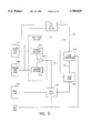
- FIG. 5 is a block diagram of the elements of the first embodiment of this invention, which includes a leading read head, a trailing read head, a write head, a write clock decoder, and write logic;
- FIG. 6 is a functional block diagram of a second embodiment of this invention.
- FIG. 7 is a functional block diagram of a fourth embodiment of this invention.
- FIG. 8 is a timing diagram of some of the signals that are relevant to the embodiment of this invention shown in FIG. 7, including a signal representative of the high frequency pattern which the write controller couples to the write head;
- FIG. 9 is a functional block diagram of a fifth embodiment of this invention.
- FIG. 10 is an illustration of the spatial relationship between each read gap and each write gap of the read/write apparatus in accordance with the embodiment of this invention shown in FIG. 9;
- FIG. 11 is a functional block diagram of a sixth embodiment of this invention.
- FIG. 12 is an illustration of the relative locations of read and write gaps within a read/write apparatus in accordance with a seventh embodiment of this invention.
- This invention is a method and apparatus for reading and writing data using a self clocking data pattern, such as the Aiken code.
- the velocity of the write head need not be constant with respect to the medium during the write operation.
- a write clock is generated by offsetting two read heads by an odd integer multiple of one half of a bit cell and combining the outputs therefrom by detecting each transition of each output and combining these transitions by a logical OR function. Accordingly, a write clock can be generated from data which is already present on the medium.
- the velocity of a read/write apparatus can be determined. Once the velocity of the read/write apparatus can be determined, a write clock can be generated.
- FIG. 3 is an illustration of the relative locations of two read gaps 301, 303 and a write gap 305 formed within a read/write apparatus 300 in accordance with one embodiment of this invention.
- the read/write apparatus 300 is similar to conventional read/write heads, with the exception of the spacing between the read and write gaps 301, 303, 305.
- a magnetic field is generated across a gap in the magnetic core material of a write head.
- the magnetic field is typically generated by applying a current through a coil wound around the magnetic core material.
- the field that is generated is sufficiently strong to polarize magnetically sensitive particles at the surface of a magnetic medium over which the write head passes.
- transitions changes (commonly referred to as "transitions" in the magnetic field generate a current in a coil wound around a magnetic core material of the read head.
- two such read gaps 301, 303 and one such write gap 305 are provided.
- the spacing between the longitudinal center lines of the read gaps 301, 303 is preferably an odd multiple of one half the bit cell distance (e.g., 1/2, 11/2, 21/2, . . . ).
- Bit cells are defined as the predetermined distance between clock transitions, when the data is written in a particular self-clocking code, such as Aiken code, in which a data transition occurring halfway between such clock transitions indicates a first logic state, and in which no transitions occurring between clock transitions indicates a second logic state.
- FIG. 4 is a timing chart which illustrates the relationship between data read by the first and second read heads.
- FIG. 5 is a block diagram of the elements of the first embodiment of this invention, which includes a leading read head 501, a trailing read head 503, a write head 505, a write clock decoder 507, and write logic 509.
- the waveforms 400, 402 shown in FIG. 4 are not the waveforms that are directly output from the read heads, but rather are those waveforms which appear at the output of a wave shaping circuit which causes a square wave to be output.
- the output has transitions from a high state 401 to a low state 403 or from a low state 403 to a high state 401 occurring each time a read head detects a transition from one polarity to the other.
- the read heads 501, 503 are assumed to include all necessary circuitry to output such signals, including amplifiers and waveshaping circuitry.
- the output 400 is from the leading read head 501 (which includes the read gap 301), and the output 402 is from the trailing read head 503 (which includes read gap 303). It can be seen that if a pulse is generated each time either the output 400 or the output 402 changes state, then the clock will be reconstructed, as shown by waveform 404. The falling edge of these pulses can be used as a read clock. These pulses can also be used directly as a write clock.
- the waveform 404 may be used to generate a write clock 406 with a frequency that is equal to the data rate when the data is all ones, and which has a 50% duty cycle, such that the rising edge 405 of the clock occurs at the beginning of each bit cell, and falling edge 407 of the clock occurs midway through each bit cell (i.e., at the times when data transitions are to occur).
- the waveform 404 can be produced by applying the waveform 400 and the waveform 402 each to a transition detector 511, 513. The outputs from each transition detector are then coupled to the inputs of a two input OR-gate 515. The output of the OR-gate is write pulse waveform 404.
- the waveform 400 is applied to one of two inputs of a two input exclusive OR-gate and the waveform 402 to the other input, with one of the inputs being delayed by the desired length of the pulses to be generated.
- One well known method for delaying a signal is to perform a double inversion.
- each waveform 400,402 can be applied to a dual edge triggered monostable multivibrator (or "one-shot") which produces a pulse each time the waveform 400,402 transitions either high or low.
- Each output from the two one-shots is then applied to a different one of the two inputs of a two input OR-gate.
- the waveform 402 is applied to both a positive edge triggered one-shot and a negative edge triggered one-shot. Each of the outputs are then coupled to a two input OR-gate. Due to the OR-gate 515, if either of the two waveforms 400, 402 transition either from a high to low or low to high, a pulse is generated. It will be understood by those skilled in the art that the pulse must be shorter than one half the bit cell when the read head is moved at maximum velocity with respect to the medium.
- the distance between the first and second read gaps 301, 303 may be any predetermined distance. However, if the distance between the first and second read gaps 301, 303 is other than half a bit cell, then the information that is read from the trailing read gap 303 must be delayed to simulate the data being received at a read gap which is an odd multiple of one half bit cell away from the leading read gap 301. For example, if the read gaps 301, 303 are spaced apart 1/4 of a bit cell, then the information that is read by the trailing read gap 303 must be delayed by twice the time between reading a transition at the leading read gap 301 and reading the same transition at the trailing read gap 303.
- the leading read gap 301 is spaced 1 bit cell from the trailing read gap 303, then the information that is read from the trailing read gap is delayed by 50% of the time between receipt at the leading read gap 301 and the trailing read gap 303.
- a delay can be implemented by either a programmable processing device which reads the input signal and generates an output signal with the appropriate delay, or by a programmable delay circuit designed from discrete components. Such programmable delay circuits are well known in the art. Once the two signals are delayed such that they are offset by an odd multiple of one half the bit cell, the signals are combined as described above to generate the write pulse waveform 404.
- the write pulse waveform 404 is coupled from the write clock decoder 507 to the write logic 509 over signal line 517.
- the write logic 509 uses the write pulse waveform 404 to determine when to change the polarity of the magnetic field that polarizes the medium (i.e., when to "write” a "transition” to the medium).
- the write logic 509 keeps track of which pulses are coincident with a clock transition and which are coincident with a data transition. It will be understood that data transitions are only written when the data associated with the particular bit cell is in the first of the two logical states (such as a logical one) and not in the second logical state (such as a zero). However, in accordance with the Aiken code, clock transitions are written every other pulse of the write pulse waveform 404 without fail.
- the write logic 509 controls the write head 505 to cause the transitions to be written to the medium.
- FIG. 6 is a functional block diagram of a second embodiment of this invention.
- a read data decoder 601 is coupled to each of the read heads 501, 503.
- the decoder 601 decodes the information read by each of the heads 501, 503. While the read data decoder preferably receives data from both the leading and trailing read heads 501, 503, only one stream of data is output from the read data decoder 601. The redundancy provided by the leading and trailing read heads 501, 503 can be used to verify the accuracy of the data.
- the read data decoder 601 determines the velocity of the read/write head over the magnetic medium by measuring the delay between the time data is read from the leading read head 501 and the time the same data is read from the trailing read head 503. The amount of time between receipt of a transition at the leading read head 501 and receipt of that transition at the trailing read head 503 will determine the velocity of the read/write head over the medium.
- a high frequency clock e.g., approximately 100 times the frequency of the bit rate may be used to determine and to characterize the velocity.
- the number of periods of the high frequency clock that have occurred starting upon detection of a transition at the leading read head 501 and ending upon detection of a transition at the trailing read head 503 can be used to characterize the velocity of the read/write head 300 over the medium.
- the exact distance between the read heads can differ from an odd multiple of 1/2 the bit cell.
- accurate spacing of the read heads at odd multiples of 1/2 the bit cell provides the most accurate measure of the velocity.
- the inertia of the medium (assuming it is the medium that is in motion) is relatively large, the velocity of the medium with respect to the read/write apparatus will not change rapidly. Therefore, assuming the measurement is initially accurate, a relatively accurate prediction of the point in time at which the next half bit cell boundary will occur can be made. Since new information as to the amount of time required to traverse a half bit cell is taken every half bit cell, the accuracy is maintained over time.
- the data which had been decoded by the read data decoder 601 (i.e., the "old" data) is coupled to a data comparator 603 over signal line 602.
- the data comparator 603 indicates when the read data decoder 601 begins reading the old data.
- the data comparator 603 also compares the old data with the data that is to be written (i.e., the "new" data).
- the new data may be coupled directly to the data comparator 603. However, alternatively the new data may be provided through write logic 509.
- the data comparator 603 Upon detecting that the trailing read head 503 has begun reading the old data, the data comparator 603 asserts a "Begin" signal to delay logic 605 over signal line 604.
- the data comparator 603 asserts a "Write" signal to the delay logic 605 over signal line 604.
- the delay logic 605 also receives information from the read data decoder 601 over signal line 606 that indicates the velocity of the read/write head with respect to the magnetic medium. This velocity information may take the form of a number of clock pulses, where the clock is a reference clock having a known frequency.
- the read data decoder 601 starts counting the number of such clock pulses each time either of the inputs transitions, and stops counting the next time one of the inputs transitions.
- the delay logic 605 asserts a "Begin" command to the write logic 509, as well as a "Write” command.
- the Begin command is delayed from the time the Begin signal is asserted over signal line 604. The amount of the delay is based upon the spacing between the write head 505 and the read heads 501, 503 from which the data provided to the comparator was read.
- the Write command is delayed from the time the Write signal is asserted by the data comparator 603. Each such delay is preferably equal to the time required for a particular portion of the magnetic medium to move from the trailing read head 503 to the write head 505.
- the write logic 509 when the write logic 509 receives the Write command, the write head will be properly positioned over the area of the magnetic medium to which the new data is to begin writing in order to overwrite the old data with the new data starting at the point at which the new data differs from the old data.
- the write logic 509 uses the write pulse waveform 404 to maintain synchronization between the old data and the new data. For example, in one embodiment of this invention, upon receipt of the Begin command at the write logic 509, the write logic begins attempting to write the new data, but does not enable the write head 505 until the delay logic sends the Write command. Once the Write command is received at the write logic 509, the new data overwrites the old data until the end of the write cycle.
- the write cycle does not end until all of the remaining old data which is contiguous with the changed data has been overwritten.
- a first bit of data is "contiguous" with a second bit of data, if a change from a logical one to a logical zero in the first bit of data would affect the magnetic polarity of the second bit of data.
- the delay logic 605 issues an "End" command.
- the End command is issued after a Write command has been issued, and in response to an "End" signal from the data comparator 603.
- the End signal indicates that the old data and the new data are once again equal.
- the End command is delayed from the End signal by an amount of time equal to the time required for the write head to be positioned over the old data which differs from the new data. If the difference between the number of zeros that have occurred in the old data and the number of zeros in the new data is even, then the polarity of the old data will not have changed as a result of the new data being written.
- the data comparator 603 calculates the difference in the number of zeros, and suppresses the End signal if the difference is odd.
- FIG. 7 is a functional block diagram of a fourth embodiment of this invention, which includes a write head 705, a leading read head 703, a trailing read head 701, a write clock decoder 707, and write logic 709.
- the write clock decoder 707 includes a trailing transition detector 711, a leading transition detector 713, and an OR-gate 715.
- the write logic 709 preferably includes a leading high frequency clock detector 717, a trailing high frequency clock detector 719, and a write controller 721.
- the fourth embodiment of this invention allows information to be written at regular predetermined intervals on a magnetic medium, such as a magnetic stripe, without controlling the velocity of the medium with respect to the read/write apparatus in the absence of preexisting data.
- a magnetic medium such as a magnetic stripe
- each of the embodiments described above rely upon preexisting data which must be read in order to generate a write pulse waveform used by the write logic 509 to time the writing of data by the write head 505.
- the embodiment illustrated in FIG. 7 does not rely on such preexisting data. Rather, the write head 705 leads the two read heads 701, 703 and writes a high frequency pattern which is then read by the two read heads which follow. That is, the medium passes first over the write head 705 and then over the leading read head 703 and finally over the trailing read head 701. Note that this direction is opposite of the direction that the medium moves with respect to the read/write apparatus in the first three embodiments described above.
- the write controller 721 commands the write head to write a high frequency pattern which transitions from a first logical state to a second logical state at a rate of approximately 50 times the track bit density.
- the write frequency is 187,500 Hz.
- a much lower frequency in the range of 2 times the track bit density of 7500 Hz could also be used.
- the higher frequency is used to prevent conventional readers from misinterpreting the few transitions left on the track in the embodiment not using the second write head.
- a timer is used to measure the difference at the read heads between the written frequency and the desired bit cell placement.
- FIG. 8 is a timing diagram of some of the signals that are relevant to the fourth embodiment of this invention, including a signal representative of the high frequency pattern 801 which the write controller 721 couples to the write head 705.
- the leading transition detector 713 will receive the pattern and provide a leading pulse waveform 803.
- Each pulse output from the leading transition detector 713 is generated in response to a transition detected at the leading read head 703.
- Both the leading and the trailing transition detectors are similar to the transition detectors 511, 513 discussed above.
- the transitions output from the write controller 721 will not necessarily be coincident with the pulses generated by the leading transition detector 713, since the velocity of the read/write head is uncontrolled.
- the leading pulse waveform 803 has been shown in FIG. 8 to have each pulse coincide with a transition of the write controller output 800.
- the fact that there is a delay between the time the first transition is written by the write head 705 and the time the first pulse is generated i.e., the time the first transition is detected at the leading read head 503 is illustrated in FIG. 8.
- the output from the leading transition detector 713 is coupled to the leading high frequency clock detector 717 over a signal line 723.
- the leading high frequency clock detector 717 asserts a "Detect" signal to the write controller 721 over a signal line 724 upon detecting the presence of the high frequency clock on signal line 723.
- the output from the leading read head 703 is coupled directly to the leading high frequency clock detector 717, which then asserts the Detect signal upon detecting the high frequency clock signal from the leading read head 703.
- the trailing transition detector 711 outputs a trailing pulse waveform 805 in which a pulse is generated for each transition of the high frequency pattern 801.
- the trailing transition detector 711 couples the trailing pulse waveform 805 to the trailing high frequency clock detector 719, which asserts a Detect signal to the write controller 721 over signal line 726 upon receipt of the high frequency pulse stream of the trailing pulse waveform 805.
- the velocity of the read/write apparatus at the time the pattern was written can be determined.
- the frequency at which the pattern is read can be determined with the frequency at which the pattern was written.
- any change in velocity between the time the pattern was written and the time pattern was read can be determined.
- the velocity of the read/write apparatus at the time the pattern is read can be determined.
- the current velocity of the read/write apparatus can be determined.
- the delay is measured by counting how many high frequency pulses were output from the leading transition detector 713 before the Detect signal was asserted by the trailing high frequency clock detector 719. Once the Detect signal has been asserted by the trailing high frequency clock detector 719, the write controller 721 can begin writing data, using a calculation of the current velocity of the read/write apparatus to determine when to write each transition (i.e., when a half bit cell has passed with respect to when the last transition has been written).
- the high frequency pattern 801 is written over a length of the medium that is at least as long as the distance between the leading and trailing read heads 703, 701.
- the trailing pulse waveform 805 is used to determine the current velocity of the read/write apparatus (i.e., when the next half bit cell is to occur), and thus the write controller 721 determines when to cause each magnetic flux transition to be written by the write head 705 by counting the number of pulses received from the trailing transition detector 711 and the relative frequency of the pulses with respect to the frequency at which the pulses were written.
- each transition detector 711, 713 is coupled to the input of the OR-gate 715. Therefore, once both the leading and trailing read heads 703, 701 are detecting the transitions of the data 807 written by the write head 705, the output from the OR-gate 715 determines when each half bit cell occurs in the same manner as described above. Accordingly, the output from the OR-gate 715 is coupled to the write controller 721 and used as a write clock to synchronize the write controller 721 to the bit cells. The write controller 721 determines that neither read head is reading the high frequency pattern by noting that the Detect signals from both the leading and trailing high frequency clock detectors have been deasserted.
- FIG. 9 is a functional block diagram of a fifth embodiment of this invention, wherein a second write head 901 is provided which trails the trailing read head 701.
- FIG. 10 is an illustration of the spacial relationship between each read gap and each write gap of the read/write apparatus in accordance with the fifth embodiment.
- a second write gap 1001 (which is included in the second write head 901) is located at the opposite end of the read/write apparatus 300 from the first write gap 305.
- the second write head 901 allows the high frequency pattern to be overwritten by data. That is, as soon as the Detect signal is asserted by the trailing high frequency clock detector 719, the write controller ceases writing the high frequency pattern with the leading write head 705 and begins writing the data with the trailing write head 901.
- the write controller 721 delays the write data by an amount which causes the trailing write head 901 to begin writing data at the same location at which the leading write head 705 began writing the high frequency pattern 801. This delay ensures that the trailing write head 901 is over a portion of the magnetic medium which can be magnetized (i.e., ensures that the trailing write head is does not attempt to write data before that head is over the magnetic medium).
- FIG. 11 is a functional block diagram of a sixth embodiment of this invention.
- a read head 703, a write head 705 and a read/write head 1101 are provided, in addition to the apparatus which was discussed in connection with the embodiment shown in FIG. 7.
- the embodiment of FIG. 11 operates essentially as does the embodiment of FIG. 9.
- the trailing read head 701 and the trailing write head 901 of FIG. 9 are replaced with a single read/write head 1101 which is capable of first reading, and then later, writing.
- the write controller 721 causes the write head 705 to write a pattern of logical ones. Since logical ones have a transition each half bit cell, the leading transition detector 713 provides an output which has a pulse every half bit cell. This output is then coupled to the write controller 713 over signal line 1103 and used as a write clock.
- the write controller begins controlling the read/write head 1101 to write data in synchronization with the write clock provided on signal line 1103.
- FIG. 12 is an illustration of the relative locations of read and write gaps within a read/write apparatus in accordance with a seventh embodiment of this invention.
- the write gap 1201 is aligned with a different track of information than are the read gaps 1202. Accordingly, information which was previously recorded on a first track may be read and used to generate a write clock which allows new information to be recorded on a second adjacent track.
- the bit cells used to record the data on the two tracks need not be identical, as long as they are each known.
- a single processing device may be used to implement each of the functional blocks described, such as the write controller, the transition detectors, etc.
- these functions may be combined in more than one processing device in any combination.
- a first processing device may perform the functions of the write clock decoder and read data decoder, while a second processing device performs the functions of the data comparator and delay logic.
- this invention is described in the context of a magnetic medium and magnetic read and write heads, this invention is applicable to any means for reading and writing data in which an Aiken code may be used.
- such means might be bar codes written on paper, optically encoded data, etc.
- the read and write heads might move with respect to the medium. Accordingly, it is to be understood that the invention is not to be limited by the specific illustrated embodiments, but only by the spirit and scope of the appended claims.
Abstract
Description
Claims (16)
Priority Applications (3)
| Application Number | Priority Date | Filing Date | Title |
|---|---|---|---|
| US08/602,247 US5780828A (en) | 1996-02-15 | 1996-02-15 | Interactive video systems |
| AU19578/97A AU1957897A (en) | 1996-02-15 | 1997-02-13 | Method and apparatus for performing spatial read-modify-write operations |
| PCT/US1997/002273 WO1997030412A1 (en) | 1996-02-15 | 1997-02-13 | Method and apparatus for performing spatial read-modify-write operations |
Applications Claiming Priority (1)
| Application Number | Priority Date | Filing Date | Title |
|---|---|---|---|
| US08/602,247 US5780828A (en) | 1996-02-15 | 1996-02-15 | Interactive video systems |
Publications (1)
| Publication Number | Publication Date |
|---|---|
| US5780828A true US5780828A (en) | 1998-07-14 |
Family
ID=24410603
Family Applications (1)
| Application Number | Title | Priority Date | Filing Date |
|---|---|---|---|
| US08/602,247 Expired - Fee Related US5780828A (en) | 1996-02-15 | 1996-02-15 | Interactive video systems |
Country Status (3)
| Country | Link |
|---|---|
| US (1) | US5780828A (en) |
| AU (1) | AU1957897A (en) |
| WO (1) | WO1997030412A1 (en) |
Cited By (19)
| Publication number | Priority date | Publication date | Assignee | Title |
|---|---|---|---|---|
| US6404356B1 (en) * | 2000-05-22 | 2002-06-11 | Cennoid Technologies, Inc. | Wave demodulation processor |
| US6571320B1 (en) * | 1998-05-07 | 2003-05-27 | Infineon Technologies Ag | Cache memory for two-dimensional data fields |
| US20030169655A1 (en) * | 1999-02-26 | 2003-09-11 | Sanyo Electric Co., Ltd. | Disk recording device |
| US6765959B1 (en) * | 1998-06-05 | 2004-07-20 | Hitachi, Ltd. | Communication method of contactless ID card and integrated circuit used in communication method |
| US6830183B2 (en) * | 2003-05-01 | 2004-12-14 | Semtek Innovative Solutions, Inc. | Device for secure read, write and read/modify/write operation with divided track transducer head |
| US20050242847A1 (en) * | 1998-03-16 | 2005-11-03 | Jazio, Inc. | High speed source synchronous signaling for interfacing VLSI CMOS circuits to transmission lines |
| US20060049255A1 (en) * | 2004-09-07 | 2006-03-09 | Clay Von Mueller | Secure magnetic stripe reader for handheld computing and method of using same |
| US20060049256A1 (en) * | 2004-09-07 | 2006-03-09 | Clay Von Mueller | Transparently securing data for transmission on financial networks |
| US20070143226A1 (en) * | 1996-02-15 | 2007-06-21 | Clay Von Mueller | Method and apparatus for securing and authenticating encoded data and documents containing such data |
| US20080091617A1 (en) * | 2006-10-17 | 2008-04-17 | Hazel Patrick K | Personal token read system and method |
| US20080189214A1 (en) * | 2006-10-17 | 2008-08-07 | Clay Von Mueller | Pin block replacement |
| US20080288403A1 (en) * | 2007-05-18 | 2008-11-20 | Clay Von Mueller | Pin encryption device security |
| US20090310778A1 (en) * | 2008-06-17 | 2009-12-17 | Clay Von Mueller | Variable-length cipher system and method |
| US7725726B2 (en) | 1996-02-15 | 2010-05-25 | Semtek Innovative Solutions Corporation | Method and apparatus for securing and authenticating encoded data and documents containing such data |
| US8144940B2 (en) | 2008-08-07 | 2012-03-27 | Clay Von Mueller | System and method for authentication of data |
| US8251283B1 (en) | 2009-05-08 | 2012-08-28 | Oberon Labs, LLC | Token authentication using spatial characteristics |
| US8355982B2 (en) | 2007-08-16 | 2013-01-15 | Verifone, Inc. | Metrics systems and methods for token transactions |
| US20150243311A1 (en) * | 2014-02-25 | 2015-08-27 | Lsi Corporation | Systems and Methods for Synchronization Hand Shaking in a Storage Device |
| CN108304891A (en) * | 2018-01-18 | 2018-07-20 | 东方通信股份有限公司 | A kind of hand-held card sending system, device and method |
Families Citing this family (1)
| Publication number | Priority date | Publication date | Assignee | Title |
|---|---|---|---|---|
| DE19821931C2 (en) * | 1998-05-15 | 2000-05-18 | Siemens Nixdorf Inf Syst | Device for recording binary information on a magnetic memory card using a DMA unit |
Citations (13)
| Publication number | Priority date | Publication date | Assignee | Title |
|---|---|---|---|---|
| GB1224251A (en) * | 1967-05-31 | 1971-03-10 | Sony Corp | Magnetic recording method and device |
| US3898689A (en) * | 1974-08-02 | 1975-08-05 | Bell Telephone Labor Inc | Code converter |
| US3949193A (en) * | 1974-01-07 | 1976-04-06 | Electrospace Corporation | Credit card reader having two magnetic readout heads |
| GB2015794A (en) * | 1978-02-24 | 1979-09-12 | Cubic Western Data | Reproduction of binary signals from a recording medium that may be read at varying speeds |
| FR2428874A1 (en) * | 1978-06-13 | 1980-01-11 | Cii Honeywell Bull | METHOD AND DEVICE FOR RECORDING INFORMATION ON A MEDIUM, PARTICULARLY MAGNETIC, INDEPENDENT OF THE SPEED OF THE MEDIUM |
| US4650978A (en) * | 1985-01-23 | 1987-03-17 | Rmh Systems, Inc. | Off line cash card system and method |
| US4858116A (en) * | 1987-05-01 | 1989-08-15 | Digital Equipment Corporation | Method and apparatus for managing multiple lock indicators in a multiprocessor computer system |
| US5091961A (en) * | 1989-07-14 | 1992-02-25 | American Magnetics Corp. | Magnetic ink character decoder |
| US5235166A (en) * | 1991-02-14 | 1993-08-10 | Xtec Incorporated | Data verification method and magnetic media therefor |
| US5317137A (en) * | 1992-02-24 | 1994-05-31 | Comproducts Inc. | Magnetic debit card reader fraudulent use prevention |
| US5397886A (en) * | 1993-06-10 | 1995-03-14 | Mos Magnetics Corporation | Magnetic stripe and/or micro chip card motorized reader/encoder mechanism |
| US5535216A (en) * | 1995-01-17 | 1996-07-09 | Digital Equipment Corporation | Multiplexed gapped constant bit rate data transmission |
| US5650606A (en) * | 1995-08-07 | 1997-07-22 | Magnetic Products International, Corp | Accurate read/write head for preventing credit card alteration and counterfeiting of debit cards |
-
1996
- 1996-02-15 US US08/602,247 patent/US5780828A/en not_active Expired - Fee Related
-
1997
- 1997-02-13 WO PCT/US1997/002273 patent/WO1997030412A1/en active Application Filing
- 1997-02-13 AU AU19578/97A patent/AU1957897A/en not_active Abandoned
Patent Citations (13)
| Publication number | Priority date | Publication date | Assignee | Title |
|---|---|---|---|---|
| GB1224251A (en) * | 1967-05-31 | 1971-03-10 | Sony Corp | Magnetic recording method and device |
| US3949193A (en) * | 1974-01-07 | 1976-04-06 | Electrospace Corporation | Credit card reader having two magnetic readout heads |
| US3898689A (en) * | 1974-08-02 | 1975-08-05 | Bell Telephone Labor Inc | Code converter |
| GB2015794A (en) * | 1978-02-24 | 1979-09-12 | Cubic Western Data | Reproduction of binary signals from a recording medium that may be read at varying speeds |
| FR2428874A1 (en) * | 1978-06-13 | 1980-01-11 | Cii Honeywell Bull | METHOD AND DEVICE FOR RECORDING INFORMATION ON A MEDIUM, PARTICULARLY MAGNETIC, INDEPENDENT OF THE SPEED OF THE MEDIUM |
| US4650978A (en) * | 1985-01-23 | 1987-03-17 | Rmh Systems, Inc. | Off line cash card system and method |
| US4858116A (en) * | 1987-05-01 | 1989-08-15 | Digital Equipment Corporation | Method and apparatus for managing multiple lock indicators in a multiprocessor computer system |
| US5091961A (en) * | 1989-07-14 | 1992-02-25 | American Magnetics Corp. | Magnetic ink character decoder |
| US5235166A (en) * | 1991-02-14 | 1993-08-10 | Xtec Incorporated | Data verification method and magnetic media therefor |
| US5317137A (en) * | 1992-02-24 | 1994-05-31 | Comproducts Inc. | Magnetic debit card reader fraudulent use prevention |
| US5397886A (en) * | 1993-06-10 | 1995-03-14 | Mos Magnetics Corporation | Magnetic stripe and/or micro chip card motorized reader/encoder mechanism |
| US5535216A (en) * | 1995-01-17 | 1996-07-09 | Digital Equipment Corporation | Multiplexed gapped constant bit rate data transmission |
| US5650606A (en) * | 1995-08-07 | 1997-07-22 | Magnetic Products International, Corp | Accurate read/write head for preventing credit card alteration and counterfeiting of debit cards |
Cited By (35)
| Publication number | Priority date | Publication date | Assignee | Title |
|---|---|---|---|---|
| US20070143226A1 (en) * | 1996-02-15 | 2007-06-21 | Clay Von Mueller | Method and apparatus for securing and authenticating encoded data and documents containing such data |
| US7543151B2 (en) | 1996-02-15 | 2009-06-02 | Semtek Innovative Solutions Corporation | Method and apparatus for securing and authenticating encoded data and documents containing such data |
| US7725726B2 (en) | 1996-02-15 | 2010-05-25 | Semtek Innovative Solutions Corporation | Method and apparatus for securing and authenticating encoded data and documents containing such data |
| US20050242847A1 (en) * | 1998-03-16 | 2005-11-03 | Jazio, Inc. | High speed source synchronous signaling for interfacing VLSI CMOS circuits to transmission lines |
| US7126383B2 (en) * | 1998-03-16 | 2006-10-24 | Jazio, Inc. | High speed source synchronous signaling for interfacing VLSI CMOS circuits to transmission lines |
| US6571320B1 (en) * | 1998-05-07 | 2003-05-27 | Infineon Technologies Ag | Cache memory for two-dimensional data fields |
| US6765959B1 (en) * | 1998-06-05 | 2004-07-20 | Hitachi, Ltd. | Communication method of contactless ID card and integrated circuit used in communication method |
| US7116709B2 (en) | 1998-06-05 | 2006-10-03 | Hitachi, Ltd. | Communication method of contactless ID card and integrated circuit used in communication method |
| US20030169655A1 (en) * | 1999-02-26 | 2003-09-11 | Sanyo Electric Co., Ltd. | Disk recording device |
| US6404356B1 (en) * | 2000-05-22 | 2002-06-11 | Cennoid Technologies, Inc. | Wave demodulation processor |
| US6830183B2 (en) * | 2003-05-01 | 2004-12-14 | Semtek Innovative Solutions, Inc. | Device for secure read, write and read/modify/write operation with divided track transducer head |
| US7309012B2 (en) | 2004-09-07 | 2007-12-18 | Semtek Innovative Solutions, Inc. | Secure magnetic stripe reader for handheld computing and method of using same |
| US8249993B2 (en) | 2004-09-07 | 2012-08-21 | Verifone, Inc. | Transparently securing data for transmission on financial networks |
| US7740173B2 (en) | 2004-09-07 | 2010-06-22 | Semtek Innovative Solutions Corporation | Transparently securing transactional data |
| US20060049256A1 (en) * | 2004-09-07 | 2006-03-09 | Clay Von Mueller | Transparently securing data for transmission on financial networks |
| US20060049255A1 (en) * | 2004-09-07 | 2006-03-09 | Clay Von Mueller | Secure magnetic stripe reader for handheld computing and method of using same |
| US7506812B2 (en) | 2004-09-07 | 2009-03-24 | Semtek Innovative Solutions Corporation | Transparently securing data for transmission on financial networks |
| US20090060199A1 (en) * | 2006-10-17 | 2009-03-05 | Clay Von Mueller | System and method for updating a transactional device |
| US9141953B2 (en) | 2006-10-17 | 2015-09-22 | Verifone, Inc. | Personal token read system and method |
| US9818108B2 (en) | 2006-10-17 | 2017-11-14 | Verifone, Inc. | System and method for updating a transactional device |
| US20080189214A1 (en) * | 2006-10-17 | 2008-08-07 | Clay Von Mueller | Pin block replacement |
| US20080091944A1 (en) * | 2006-10-17 | 2008-04-17 | Von Mueller Clay W | Batch settlement transactions system and method |
| US9123042B2 (en) | 2006-10-17 | 2015-09-01 | Verifone, Inc. | Pin block replacement |
| US20080091617A1 (en) * | 2006-10-17 | 2008-04-17 | Hazel Patrick K | Personal token read system and method |
| US8769275B2 (en) | 2006-10-17 | 2014-07-01 | Verifone, Inc. | Batch settlement transactions system and method |
| US8595490B2 (en) | 2006-10-17 | 2013-11-26 | Verifone, Inc. | System and method for secure transaction |
| US20080288403A1 (en) * | 2007-05-18 | 2008-11-20 | Clay Von Mueller | Pin encryption device security |
| US8355982B2 (en) | 2007-08-16 | 2013-01-15 | Verifone, Inc. | Metrics systems and methods for token transactions |
| US9361617B2 (en) | 2008-06-17 | 2016-06-07 | Verifone, Inc. | Variable-length cipher system and method |
| US20090310778A1 (en) * | 2008-06-17 | 2009-12-17 | Clay Von Mueller | Variable-length cipher system and method |
| US8144940B2 (en) | 2008-08-07 | 2012-03-27 | Clay Von Mueller | System and method for authentication of data |
| US8251283B1 (en) | 2009-05-08 | 2012-08-28 | Oberon Labs, LLC | Token authentication using spatial characteristics |
| US20150243311A1 (en) * | 2014-02-25 | 2015-08-27 | Lsi Corporation | Systems and Methods for Synchronization Hand Shaking in a Storage Device |
| US9672850B2 (en) * | 2014-02-25 | 2017-06-06 | Avago Technologies General Ip (Singapore) Pte. Ltd. | Systems and methods for synchronization hand shaking in a storage device |
| CN108304891A (en) * | 2018-01-18 | 2018-07-20 | 东方通信股份有限公司 | A kind of hand-held card sending system, device and method |
Also Published As
| Publication number | Publication date |
|---|---|
| AU1957897A (en) | 1997-09-02 |
| WO1997030412A1 (en) | 1997-08-21 |
Similar Documents
| Publication | Publication Date | Title |
|---|---|---|
| US5780828A (en) | Interactive video systems | |
| US7031097B1 (en) | Systems and methods for using noise measurement tracks with servopositioning signals | |
| CA2030872C (en) | Disk file or tape drive with high servo sample rate | |
| JP2845915B2 (en) | Information reproducing method and information reproducing apparatus | |
| JPH1116137A (en) | Servo system which tracks magnetic track having identification pulse width | |
| US6023385A (en) | Tape servo pattern with enhanced synchronization properties | |
| EP0950245B1 (en) | Method and apparatus for writing a clock track on a storage medium | |
| JP5651173B2 (en) | Method, program and apparatus for controlling dual channel weighted LPOS combining scheme | |
| US5920438A (en) | Programmable digital centerline tracking threshold apparatus and method | |
| EP0996114B1 (en) | Servo system and method with multiple phase clock | |
| JP3621149B2 (en) | Synchronization pattern reading method, synchronization pattern detection circuit, address mark detection circuit | |
| JPH02257417A (en) | Method for recording and detecting servo information for positioning magnetic head | |
| CA1104719A (en) | Read apparatus | |
| US5973869A (en) | Servo frame edge detection for tape servo pattern with synchronization field | |
| WO1992000589A1 (en) | Read/write control for disk drive | |
| JPS59113516A (en) | Multichannel reading signal reproduction system | |
| EP0630018B1 (en) | Interblock gap detection in a data storage system | |
| US6072650A (en) | Data placement variation compensation system | |
| US5363252A (en) | Method and system for track skew tolerant acquistion burst sequence validation in a data storage system | |
| US5223989A (en) | Data detection circuit having a pulse shape and amplitude measuring sampling detector | |
| US4633333A (en) | Detection of instantaneous speed variations in a tape drive | |
| US5696641A (en) | Method using a biasing pattern on a magnetic storage media to reduce MR head noise | |
| JPS6396716A (en) | Tape edge detecting system | |
| JPS62119770A (en) | Magnetic recording and reproducing device | |
| ATE107071T1 (en) | VARIABLE SPEED PLAYBACK AND DECODING OF RECORDED DATA USING A MAGNETO-RESISTIVE SENSOR. |
Legal Events
| Date | Code | Title | Description |
|---|---|---|---|
| AS | Assignment |
Owner name: DH TECHNOLOGIES, INC., CALIFORNIA Free format text: ASSIGNMENT OF ASSIGNORS INTEREST;ASSIGNORS:MOS, ROBERT;MUELLER, CLAY VON;REEL/FRAME:007877/0278 Effective date: 19960213 |
|
| AS | Assignment |
Owner name: DH TECHNOLOGY, INC., CALIFORNIA Free format text: TO CORRECT BOX 2 OF ASSIGNMENT RECORDATION AND NAME OF ASSIGNEE ON ASSIGNMENT.;ASSIGNORS:MOS, ROBERT;VON MUELLER, CLAY;REEL/FRAME:008065/0973 Effective date: 19960214 |
|
| AS | Assignment |
Owner name: DH TECHNOLOGY INC., CALIFORNIA Free format text: ASSIGNMENT OF ASSIGNORS INTEREST;ASSIGNORS:MOS, ROBERT;VON MUELLER, CLAY;REEL/FRAME:008196/0934 Effective date: 19960325 |
|
| AS | Assignment |
Owner name: SEMTEK INNOVATIVE SOLUTIONS CORPORATION, CALIFORNI Free format text: ASSIGNMENT OF ASSIGNORS INTEREST;ASSIGNOR:AXIOHM TRANSACTIONS SOLUTIONS, INC.;REEL/FRAME:011967/0758 Effective date: 20010510 |
|
| FEPP | Fee payment procedure |
Free format text: PAT HOLDER CLAIMS SMALL ENTITY STATUS, ENTITY STATUS SET TO SMALL (ORIGINAL EVENT CODE: LTOS); ENTITY STATUS OF PATENT OWNER: SMALL ENTITY |
|
| FEPP | Fee payment procedure |
Free format text: PAYOR NUMBER ASSIGNED (ORIGINAL EVENT CODE: ASPN); ENTITY STATUS OF PATENT OWNER: SMALL ENTITY |
|
| FPAY | Fee payment |
Year of fee payment: 4 |
|
| AS | Assignment |
Owner name: CIT GROUP/BUSINESS CREDIT, INC., THE, NEW YORK Free format text: SECURITY AGREEMENT;ASSIGNOR:AXIOHM TRANSCATION SOLUTIONS, INC.;REEL/FRAME:014491/0308 Effective date: 20030918 |
|
| REMI | Maintenance fee reminder mailed | ||
| FPAY | Fee payment |
Year of fee payment: 8 |
|
| SULP | Surcharge for late payment |
Year of fee payment: 7 |
|
| REMI | Maintenance fee reminder mailed | ||
| LAPS | Lapse for failure to pay maintenance fees | ||
| STCH | Information on status: patent discontinuation |
Free format text: PATENT EXPIRED DUE TO NONPAYMENT OF MAINTENANCE FEES UNDER 37 CFR 1.362 |
|
| FP | Lapsed due to failure to pay maintenance fee |
Effective date: 20100714 |
|
| AS | Assignment |
Owner name: VERIFONE SYSTEMS, INC., CALIFORNIA Free format text: ASSIGNMENT OF ASSIGNORS INTEREST;ASSIGNOR:SEMTEK INNOVATIVE SOLUTIONS CORPORATION;REEL/FRAME:025177/0121 Effective date: 20101021 |
|
| AS | Assignment |
Owner name: VERIFONE, INC., CALIFORNIA Free format text: ASSIGNMENT OF ASSIGNORS INTEREST;ASSIGNOR:VERIFONE SYSTEMS, INC.;REEL/FRAME:025328/0286 Effective date: 20101103 |