US5720533A - Brake control system - Google Patents
Brake control system Download PDFInfo
- Publication number
- US5720533A US5720533A US08/732,582 US73258296A US5720533A US 5720533 A US5720533 A US 5720533A US 73258296 A US73258296 A US 73258296A US 5720533 A US5720533 A US 5720533A
- Authority
- US
- United States
- Prior art keywords
- block
- vehicle
- yaw rate
- wheel
- determining
- Prior art date
- Legal status (The legal status is an assumption and is not a legal conclusion. Google has not performed a legal analysis and makes no representation as to the accuracy of the status listed.)
- Expired - Fee Related
Links
Images


Classifications
-
- B—PERFORMING OPERATIONS; TRANSPORTING
- B60—VEHICLES IN GENERAL
- B60T—VEHICLE BRAKE CONTROL SYSTEMS OR PARTS THEREOF; BRAKE CONTROL SYSTEMS OR PARTS THEREOF, IN GENERAL; ARRANGEMENT OF BRAKING ELEMENTS ON VEHICLES IN GENERAL; PORTABLE DEVICES FOR PREVENTING UNWANTED MOVEMENT OF VEHICLES; VEHICLE MODIFICATIONS TO FACILITATE COOLING OF BRAKES
- B60T8/00—Arrangements for adjusting wheel-braking force to meet varying vehicular or ground-surface conditions, e.g. limiting or varying distribution of braking force
- B60T8/17—Using electrical or electronic regulation means to control braking
- B60T8/175—Brake regulation specially adapted to prevent excessive wheel spin during vehicle acceleration, e.g. for traction control
-
- B—PERFORMING OPERATIONS; TRANSPORTING
- B60—VEHICLES IN GENERAL
- B60T—VEHICLE BRAKE CONTROL SYSTEMS OR PARTS THEREOF; BRAKE CONTROL SYSTEMS OR PARTS THEREOF, IN GENERAL; ARRANGEMENT OF BRAKING ELEMENTS ON VEHICLES IN GENERAL; PORTABLE DEVICES FOR PREVENTING UNWANTED MOVEMENT OF VEHICLES; VEHICLE MODIFICATIONS TO FACILITATE COOLING OF BRAKES
- B60T8/00—Arrangements for adjusting wheel-braking force to meet varying vehicular or ground-surface conditions, e.g. limiting or varying distribution of braking force
- B60T8/17—Using electrical or electronic regulation means to control braking
- B60T8/1755—Brake regulation specially adapted to control the stability of the vehicle, e.g. taking into account yaw rate or transverse acceleration in a curve
-
- B—PERFORMING OPERATIONS; TRANSPORTING
- B60—VEHICLES IN GENERAL
- B60T—VEHICLE BRAKE CONTROL SYSTEMS OR PARTS THEREOF; BRAKE CONTROL SYSTEMS OR PARTS THEREOF, IN GENERAL; ARRANGEMENT OF BRAKING ELEMENTS ON VEHICLES IN GENERAL; PORTABLE DEVICES FOR PREVENTING UNWANTED MOVEMENT OF VEHICLES; VEHICLE MODIFICATIONS TO FACILITATE COOLING OF BRAKES
- B60T8/00—Arrangements for adjusting wheel-braking force to meet varying vehicular or ground-surface conditions, e.g. limiting or varying distribution of braking force
- B60T8/17—Using electrical or electronic regulation means to control braking
- B60T8/176—Brake regulation specially adapted to prevent excessive wheel slip during vehicle deceleration, e.g. ABS
Definitions
- This invention relates to a brake control system and method.
- ABS anti-lock brake control
- TCS positive acceleration traction control
- this invention provides a brake control system for actively controlling the brakes of a motor vehicle.
- this invention provides a brake control system that provides closed loop yaw control by developing a yaw rate command from operator inputs such as vehicle speed and steering wheel position.
- This invention provides a control that minimizes yaw rate error, which is the difference between the yaw rate command and the actual vehicle yaw rate.
- this invention recognizes that a vehicle handling response is dynamic, varying with vehicle speed in a non-linear manner.
- Closed loop control commands are provided through a control structure that is also dynamic, varying nonlinearly with vehicle speed as the vehicle handling response changes.
- the control structure uses proportional and derivative terms determined using gains that vary nonlinearly with vehicle speed, thus matching the control response to the vehicle response.
- this invention provides closed loop control commands responsive to the yaw rate error in a dual command structure, a first command is provided as a front or rear axle command and a second command is provided as a left or right torque command.
- the axle command is provided to either of the front or rear axles to modify wheel speeds on those axles to increase wheel-to-road traction in a manner to vary the vehicle yaw rate.
- the torque command is provided to one or more wheels to impart a left or right torque moment on the vehicle body through modification of the braking action of the wheels.
- Actual vehicle yaw rate is monitored so that the closed loop control takes into account the results of the axle and torque moment commands when updating the commands.
- this invention provides a brake control method for use in a vehicle with first and second front vehicle wheels and third and fourth rear vehicle wheels, the brake control method comprising the steps of: determining a desired vehicle yaw rate; determining an actual vehicle yaw rate; determining a vehicle speed; responsive to the vehicle speed and a first nonlinear control function, determining a proportional gain, wherein the proportional gain varies nonlinearly with vehicle speed; responsive to the vehicle speed and a second nonlinear control function, determining a derivative gain, wherein the derivative gain varies nonlinearly with vehicle speed; responsive to the proportional gain, the derivative gain and the desired and actual vehicle yaw rates, determining a torque command; applying the torque command to at least one of the vehicle wheels to create a yaw torque moment on the vehicle body, wherein a difference between the desired vehicle yaw rate and the actual vehicle yaw rate is minimized and wherein the brake control response varies nonlinearly with vehicle speed to match
- this invention provides a brake control method for use in a vehicle with first and second front vehicle wheels and third and fourth rear vehicle wheels and at least one member of a first group comprising anti-lock brake control and positive acceleration traction control, the brake control method comprising the steps of: determining a desired vehicle yaw rate; determining an actual vehicle yaw rate; responsive to the desired and actual vehicle yaw rates, determining an axle command; responsive to the desired and actual vehicle yaw rates, determining a torque command; applying the axle command during activation of one of the anti-lock brake control and the positive acceleration traction control to one member of a second group comprising (i) the two front wheels and (ii) the two rear wheels, wherein wheel-to-road traction is increased and a difference between desired vehicle yaw rate and actual vehicle yaw rate is minimized; and applying the torque command to at least one of the vehicle wheels independently of the axle command to create a yaw torque moment on the vehicle body with respect to the road
- FIG. 1 is an example schematic of a vehicle brake control system according to this invention
- FIG. 2 illustrates a master flow diagram for example operation of controller 68 in FIG. 1;
- FIG. 3 illustrates an example control structure according to this invention
- FIG. 4 illustrates an example control structure of block 1412 of FIG. 3
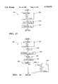
- FIG. 5 illustrates an example control structure of block 1414 FIG. 3
- FIG. 6 illustrates an example flow control for block 104 of FIG. 2
- FIG. 7 illustrates an example flow control of block 450 of FIG. 6
- FIG. 8 illustrates a plot of an example yaw gain of a typical vehicle in response to vehicle speed and steering wheel angle
- FIG. 9 illustrates a plot of an example yaw gain function according to this invention.
- FIG. 10 illustrates an example flow control of block 452 of FIG. 6;
- FIG. 11 illustrates an example plot of a look-up table function of block 508 of FIG. 10
- FIG. 12 illustrates an example flow control of blocks 458 and 460 of FIG. 6;
- FIG. 13 illustrates an example plot of a look-up table function of block 536 of FIG. 12;
- FIG. 14 illustrates an example plot of a look-up table function of block 550 of FIG. 15;
- FIG. 15 illustrates an example flow control of block 464 of FIG. 6
- FIG. 16 illustrates an example plot of a coefficient for a filter implemented at block 451 in FIG. 6;
- FIG. 17 illustrates an example plot of another coefficient for a filter implemented at block 451 of FIG. 6;
- FIG. 18 illustrates an example flow control of block 106 of FIG. 2
- FIG. 19 illustrates an example flow control of block 602 of FIG. 18
- FIG. 20 illustrates an example flow control of block 670 of FIG. 19
- FIG. 21 illustrates an example flow control of block 604 of FIG. 18
- FIG. 22 illustrates an example plot of a look-up table function of block 652 of FIG. 21;
- FIG. 23 illustrates an example plot of a look-up table function of block 654 of FIG. 21;
- FIG. 24 illustrates an example flow control for activating active brake control
- FIG. 25 illustrates an example flow control for deactivating active brake control
- FIG. 26 illustrates example additional flow control for deactivating active brake control
- FIG. 27 illustrates an example flow control for block 108 of FIG. 2
- FIG. 28 illustrates an example flow control for block 804 of FIG. 27;
- FIG. 29 illustrates an example flow control for block 806 of FIG. 27
- FIG. 30 illustrates an example flow control for block 852 of FIG. 29
- FIG. 31 illustrates an example flow control for block 808 of FIG. 27
- FIG. 32 illustrates an example flow control for determining vehicle velocity and four wheel reference velocities
- FIG. 33 illustrates an example flow control for block 110 of FIG. 2;
- FIG. 34 illustrates an example flow control for block 152 of FIG. 33
- FIG. 35 illustrates an example flow control for block 158 of FIG. 33
- FIG. 36 illustrates an example flow control for configuring the example system to the vehicle
- FIG. 37 illustrates another example flow control for configuring the example system to the vehicle
- FIG. 38A illustrates an example flow control for block 200 of FIG. 35;
- FIG. 38B illustrates additional example flow control for block 200 of FIG. 35;
- FIG. 38C illustrates further additional example flow control for block 200 of FIG. 35;
- FIG. 39 illustrates an example flow control for block 202 of FIG. 35
- FIG. 40 illustrates an example relationship between vehicle reference speed and maximum allowed delta velocity
- FIG. 41A illustrates an example flow control for block 204 of FIG. 35
- FIG. 41B illustrates additional example flow control for block 204 of FIG. 35.
- FIG. 42 illustrates example flow control for block 208 of FIG. 42.
- the vehicle 10 shown includes a controllable brake system with controller 68 for controlling the brakes 20, 22, 24 and 26 for wheels 12, 14, 16 and 18, respectively.
- controller 68 for controlling the brakes 20, 22, 24 and 26 for wheels 12, 14, 16 and 18, respectively.
- Various inputs to the controller 68 include the wheel speed signals on lines 36, 38, 40 and 42 from wheel speed sensors 28, 30, 32 and 34, the brake pedal switch signal on line 84 from brake pedal switch 82, the brake pedal extended travel signal on line 83 from pedal travel sensor 85 (optional), the steering wheel angle signal on line 62 from sensor 61 indicating the angle of steering wheel 60, the yaw rate signal on line 81 from yaw rate sensor 80, the master cylinder pressure signal on line 96 from master cylinder pressure sensor 94 (optional) and the lateral acceleration signal on line 99 from lateral accelerometer 98.
- the brake pedal travel sensor 85 is a switch mounted to the pedal that provides an output signal when the pedal has been depressed an extended amount indicating "hard” braking by the driver.
- the steering wheel position sensor 61 may be a digital sensor that provides output signals that increment a digital position signal within controller 68 with each degree or partial degree of movement of the steering wheel 60 in one direction and decrement the digital position signal with each degree or partial degree of movement in the opposite direction.
- the steering wheel sensor 61 may also include an analog sensor position output (i.e., from a rotary resistive device of a known type) that provides approximate steering wheel position information.
- the analog output can be used, for example, to determine whether the steering wheel is turned less than a preset limit, i.e., 90 degrees, at vehicle start-up.
- a method for determining the center position of the steering wheel position sensor is disclosed in pending U.S. patent application, Ser. No. 08/664,321, assigned to the assignee of this invention.
- the controller controls the braking of each wheel in anti-lock braking mode during certain braking maneuvers and in traction control mode during certain vehicle acceleration maneuvers to maintain tractive force of the drive wheels on the road surface.
- the anti-lock brake control and positive acceleration traction control are performed in a known manner except as modified herein.
- the controller 68 also actively controls the wheel brakes 20, 22, 24 and 26 responsive to the actual vehicle yaw rate as measured by yaw rate sensor 80 to minimize the difference between the actual vehicle yaw rate and a desired vehicle yaw rate. Because the base braking, antilock braking and traction control functions are known to those skilled in the art, only a general description thereof will be set forth herein.
- the controller monitors the wheel speed signals from sensors 28, 30, 32 and 34 and determines if one or more of the wheels is in or is about to be in an incipient lock-up condition, in which case anti-lock brake control mode for the one or more wheels is activated.
- the controller 68 determines and outputs commands to the actuators 52, 54, 56 and 58 corresponding to the wheels in anti-lock brake mode to modulate brake force to the wheels.
- the controller prevents the wheels from entering a lock-up condition while achieving effective brake control and steeribility in a manner known to those skilled in the art of anti-lock brake control.
- the controller 68 monitors the wheel speeds sensed by sensors 28, 30, 32 and 34 to determine if the wheels transferring motive force to the road surface are slipping or are about to slip. In such wheel conditions, the controller 68 sends commands to the actuators 52-58 corresponding to the wheels that are slipping or are about to slip to provide brake force to the wheels to reduce the slip. Such control is typically performed in conjunction with a parallel control in the engine or motor controller to temporarily reduce the motive force output until wheel to road traction is reestablished.
- the brake actuators 52-58 are implemented as reciprocating piston actuators of a type known to those skilled in the art. Such actuators typically include a dc motor positionally controlling a reciprocating piston through a rotary to linear motion converter to increase and/or decrease hydraulic pressure in the wheel brakes.
- brake actuators 52-58 are implemented as solenoid valves for selectively coupling brakes 20-26 to a source of pressurized hydraulic fluid to increase brake pressure and for selectively coupling brakes 20-26 to a brake fluid reservoir to decrease brake pressure. Implementation of such solenoid valves is known to those skilled in the art.
- the rear brakes and/or the front brakes may be electric motor-driven brakes, in which case the actuator and brake functions are performed by the same unit.
- An example of a brake system including front hydraulic brakes and rear electric brakes in which all four brakes are drive-by-wire is set forth in U.S. Pat. No. 5,366,291, assigned to the assignee of this invention.
- This invention performs an active brake control of the four wheel brakes 20-26 responsive to the steering wheel angle signal on line 62, the yaw rate signal on line 81, the vehicle speed as calculated responsive to the signals from the four wheel speed sensors and the lateral acceleration signal on line 99. Using these signals, controller 68 determines a desired vehicle yaw rate and compares that desired yaw rate to the actual yaw rate sensed by sensor 80.
- controller 68 determines and outputs commands to actuators 52, 54, 56 and 58 to control the vehicle wheel brakes 20, 22, 24 and 26 to bring the vehicle yaw rate into conformance with the desired yaw rate.
- controller 68 typically includes a microprocessor, ROM and RAM and appropriate input and output circuits of a known type for receiving the various input signals and for outputting the various control commands to the actuators 52, 54, 56 and 58.
- FIG. 2 a master flow diagram for control by the controller 68 is shown.
- the control starts and moves to block 102 where the controller receives the various inputs from the various sensors illustrated in FIG. 1.
- the routine moves to block 104 where a subroutine is implemented to convert the sensor information received at block 102 into a desired yaw rate command, ⁇ D .
- block 104 determines two parallel desired yaw rate commands, and understeer command, ⁇ DU , and an oversteer command, ⁇ DO .
- the parallel running commands ⁇ DU and ⁇ DO are each maintained according to their own independent criteria allowing independent calibration of oversteer and understeer modes.
- the control described further below can then switch between the understeer and oversteer yaw rate commands, ⁇ DU and ⁇ DO , as the vehicle switches between understeer and oversteer modes.
- the steps performed at block 104 are described in further detail with reference to FIGS. 6-17.
- variable dead band control determines, responsive to the various sensor signals received at block 102, whether the vehicle is in understeer or in oversteer mode.
- Block 106 also determines a yaw rate dead band, DB, which varies with the vehicle conditions as represented by the sensor signals and which may vary depending upon whether the vehicle is in understeer or oversteer mode.
- DB yaw rate dead band
- variable dead band control block 106 determines whether actual vehicle yaw rate, ⁇ M , as measured by the yaw rate sensor 80, varies from the desired vehicle yaw rate as determined at block 104 by an amount greater than the dead band. If the difference between the actual yaw rate and the desired yaw rate is less than the dead band amount and the ABC flag is reset, indicating that active brake control is not active, then the ABC flag is maintained reset and active brake control is not performed at blocks 108-114.
- the ABC flag is set to active, setting the active brake control active. If the ABC flag is active and the yaw rate error, ⁇ E , is less than an exit dead band, then an exit strategy from the active brake control is commenced and if the yaw rate error continues to be below the exit dead band throughout the exit procedure, then the ABC flag is reset, terminating active brake control until the yaw rate error again rises above the dead band.
- a closed loop yaw rate control subroutine is implemented to provide yaw rate control commands responsive to the yaw rate error, ⁇ E , determined at block 106.
- the control at block 108 provides a dual command structure and preferably uses a PD or PID control for each of the dual structures.
- the dual structure addresses yaw rate error with both a front/rear control and a left/right control.
- the front/rear control recognizes that when front wheels or rear wheels undergo slip, the lateral force control provided by the wheels is reduced. By reducing the amount of slip experienced by the front or rear wheels, the lateral wheel-to-road force is increased.
- the front-to-rear control commands reduced slip at either the front axle or the rear axle to increase lateral force between either the front wheels and the road or the rear wheels and the road allowing the improved tractive force to reduce the YAW rate error.
- a left/right control operates on one or more of the four vehicle wheels independent of the front/rear control.
- the left/right control is designed to add a torque moment to the vehicle counter to the direction of yaw rate error, ⁇ E , to return the vehicle to the desired yaw rate, ⁇ DO or ⁇ DU . This is achieved by either increasing brake pressure on one wheel, decreasing brake pressure on one wheel, or increasing brake pressure on one wheel and decreasing brake pressure on another wheel.
- the modification to the brake pressure(s) create the desired torque moment in the vehicle body to achieve the desired yaw control.
- this invention is implemented using closed loop wheel speed control and thus the front/rear command, ⁇ V FR , and the left/right command, ⁇ V FR , are determined as wheel delta velocity commands, that is, ⁇ V FR and ⁇ V FR command wheel speeds to be applied to certain of the vehicle wheels commanding those wheels to have a speed different from the reference speed of the wheels.
- Block 1404 represents the command generator, for example, according to blocks 104 and 106 above, that provides understeer and oversteer desired yaw rates to blocks 1406 and 1408, respectively.
- Block 1406 subtracts the measured yaw rate from the understeer desired yaw rate and block 1408 subtracts the measured yaw rate from the oversteer desired yaw rate.
- the results of block 1406 and 1408 are provided to block 1410, which, for purposes of explanation, is shown as a multiplexer 1410.
- Line 1409 carries a signal output by block 1404 indicating whether the vehicle is in oversteer or in understeer. If the vehicle is in oversteer, then block 1410 couples the output of block 1408 to command generators 1412 and 1414. Otherwise the output of block 1406 is coupled to command generators 1412 and 1414. The output of block 1410 represents the error between the actual vehicle yaw rate and the deadband.
- Block 1412 responds to the error between the actual vehicle yaw rate and the deadband by generating the axle command ⁇ V FR , which, in the example shown, interacts with the operation of anti-lock brake and positive acceleration traction control block 1402.
- This interaction is represented by the intercept block 1416, which modifies (i.e., as described below with reference to FIGS. 32-34) the antilock brake and/or traction control commands to the wheel brakes represented by block 1420 to reduce wheel slip allowed on the axle (i.e., front wheels or rear wheels) being controlled by the antilock brake and/or traction control.
- the amount of reduction of allowed wheel slip is relational to the magnitude of the command from block 1412, which in turn is relational to the difference between the measured vehicle yaw rate and the deadband.
- the effect of the control commanded by block 1412 on the vehicle wheels 1422 vis-a-vis the wheel brakes 1420 is sensed by the wheel speed sensors, represented by line 1426, and is provided back to the command block 1404 and the antilock and traction control block 1402.
- the effect of the control commanded by block 1412 on the vehicle body 1424 is measured by the vehicle yaw rate and lateral acceleration sensors, represented by line 1428, and provided back to the command block 1404.
- block 1412 The flags indicating whether antilock brake control or positive acceleration traction control are active are provided to blocks 1502 and 1508.
- the flag indicating whether the vehicle is in oversteer or understeer is also provided to blocks 1502 and 1508. If the antilock brake control is active when the vehicle is in the understeer state (as indicated by the oversteer/understeer flag), then block 1502 sets the proportional gain to zero and block 1508 sets the derivative gain to zero.
- the proportional and derivative gains are also set to zero if all of the following conditions are met: the vehicle is in oversteer, the antilock brake control is inactive and the drive train is front wheel drive. Otherwise block 1502 sets the proportional gain equal to a predetermined constant and block 1508 sets the derivative gain as described below.
- Block 1504 multiplies the output of block 1410 by the proportional gain and provides the result to block 1512.
- the output of block 1410 is also differentiated at block 1506 and the result is provided to blocks 1505 and 1507.
- Block 1507 multiplies the output of block 1506 by the output of block 1410 and provides the result to block 1508.
- a converging gain is selected at block 1508 and given a negative sign. If the vehicle is in oversteer and the output of block 1507 is positive, then a diverging gain is selected at block 1508 and given a negative sign. If the vehicle is in oversteer and the output of block 1507 is negative, then a converging gain is selected at block 1508 and given a positive sign.
- the converging and diverging gains may be set differently for oversteer and understeer modes.
- Block 1505 imparts an absolute value function on the output of block 1506 and the result is provided to block 1510.
- Block 1510 multiplies the output of block 1508 by the output of block 1505 and the result is summed at block 1512 to the output of block 1504.
- the result of block 1512 is the axle command ⁇ V FR .
- block 1414 responds to the error between the actual vehicle yaw rate and the deadband by generating the torque command ⁇ V LR , which, in the example shown, interacts with the vehicle wheel brakes 1420 through the wheel speed control block 1418 (described further below), commanding application and/or release of brake pressure to one or more of the wheel brakes.
- the brake control in this manner creates a difference in right-to-left braking forces, inducing a torque on the vehicle body with respect to the road surface to counter the vehicle yaw rate error.
- the resultant operation of the vehicle wheels is sensed by the wheel speed sensors 1426, and fed back to the wheel speed control 1418 and back to the command block 1404.
- the effect of the torque control on the vehicle body 1424 is measured by the yaw rate and lateral acceleration sensors 1428 and fed back to the command block 1404 and summation blocks 1406 and 1408.
- Block 1450 and 1452 schedule the proportional and derivative gains nonlinearly with respect to vehicle speed. Selecting the gains in response to vehicle speed provides control advantages according to this invention conducive to the automotive vehicle. These advantages are explained as follows.
- the automotive vehicle is a dynamic system in which the road performance varies with vehicle speed.
- An example of the dynamic nature of the vehicle is illustrated in FIG. 8, showing that as vehicle speed changes, the vehicle yaw gain in response to a steering input changes drastically. As is further apparent from FIG. 8, the change in yaw gain is nonlinear with respect to vehicle speed.
- the gains for the control are also allowed to change nonlinearly with vehicle speed.
- Properly selecting the nonlinear gain functions (examples provided below with reference to FIG. 29) provides a control with a dynamic nonlinear response that varies with vehicle speed in a manner correlated with the nonlinear speed-related dynamics of the vehicle. In other words, the control response changes appropriately as the vehicle response changes with vehicle speed.
- Block 1454 multiplies the result of block 1450 by the output of block 1410 and the result is provided to summation block 1478.
- Block 1455 differentiates the output of block 1410 and the result is multiplied at block 1456 by the output of block 1452.
- the result of block 1456 is also provided to summation block 1478.
- the output of block 1410 is also provided to block 1458, which provides an output signal equal to zero if the magnitude of the output from block 1410 is less than the deadband determined by the command block 1404 (FIG. 2). Otherwise the output of block 1458 is set equal to one.
- Block 1460 multiplies the output of block 1458 by the output of block 1410 and the result is provided to summation block 1464 and to enabling block 1462, which enables the deadband to the summation block 1464 only if the output of block 1460 is not equal to zero.
- Block 1464 sums the outputs of blocks 1460 and 1462 (note, if the output of block 1460 is less than zero, then the output of block 1462 is summed in the positive, otherwise, it is summed in the negative).
- Block 1466 multiplies the output of block 1464 by the predetermined integral gain and the result is provided to block 1470.
- Block 1470 sums the output of block 1466 with the output of block 1476 (described below) and provides the result to block 1476.
- the output of block 1464 is also provided to enable block 1474, which enables the constant on line 1475 to block 1472 only when the output of block 1464 is equal to zero. If so, block 1472 subtracts the constant on line 1475 from the output of block 1476 and the result is provided to block 1476.
- Block 1476 is shown as a multiplexer that selects between the outputs of blocks 1470 and 1472 and the zero input. The zero input is selected whenever the output of block 1477, which multiplies the desired yaw rate by the filtered yaw rate error, is negative. A negative output by block 1477 indicates a change in steered direction of the vehicle has occurred. Otherwise, block 1476 selects the output of block 1470 when the output of block 1464 is not equal to zero and selects the output of block 1472 when the output of block 1464 is equal to zero.
- Block 1478 sums the outputs of blocks 1454, 1456 and 1476 and provides the result as ⁇ V LR .
- blocks 1458-1477 provide increased response of the control by limiting the operation of the integral term.
- integral terms add an ability to correct for steady state error at the price of building additional lag into the system.
- Blocks 1458-1477 limit the lag of the system for example: (a) by providing a fixed aggressive decay rate (blocks 1472 and 1474) when the output of block 1410 is less than the deadband; and (b) by resetting the integral term to zero (blocks 1476 and 1477) whenever a change in steering direction occurs.
- the controller performs a force distribution control which applies the commands ⁇ V FR and ⁇ V LR to the vehicle wheels.
- the force distribution control at block 110 operates as follows. If the vehicle is in an anti-lock braking mode in which the vehicle brakes are controlled by driver commanded braking to prevent wheel lock up, the left/right command is applied to only one of the four vehicle wheels to command a release of brake pressure at the vehicle wheel, introducing the desired torque moment in the vehicle body by the left-to-right brake difference resulting from the commanded release.
- the left/right control command is applied to only one of the four vehicle wheels to apply brake pressure to that wheel.
- the brake pressure applied to the one wheel creates a left-to-right brake difference creating a torque moment on the vehicle body to reduce the YAW rate error.
- the left/right yaw control command is applied to two of the four vehicle wheels releasing brake pressure in one of the wheels and applying brake pressure to the other. The resulting difference in left right brake forces create a torque moment on the vehicle body that minimizes the yaw rate error.
- Block 110 also interacts the front/rear control with the anti-lock brake and positive acceleration traction controls.
- ⁇ V FR is applied by modifying the amount of braking to one of the axles, i.e., the rear axle, reducing the average brake pressure to that axle, increasing that axle's holding force on the road surface.
- the front/rear command, ⁇ V FR is applied by reducing the target wheel spin. This has the effect of reducing the average wheel spin during acceleration, increasing the lateral holding force of the drive wheels.
- FIG. 6 illustrates a main subroutine performed by the driver command interpreter.
- the routine determines a desired steady state yaw rate command, ⁇ SS , as described below with reference to FIG. 7.
- Block 451 filters the command ⁇ SS and then block 452 determines a bank angle compensation term, BK, as described below with reference to FIG. 10.
- the routine determines the desired yaw rate, ⁇ D , as the sum of ⁇ SS and BK.
- Block 456 is shown as a decision block to illustrate two possible implementations of this invention.
- the control routine retains as much command authority during understeer as it retains during oversteer whereas in the example shown by blocks 462 and 464, the understeer authority is limited to temper the system's response to occurrence of understeer.
- the decision to use blocks 458 and 460 or blocks 462 and 464 can be preprogrammed as a preset variable for a particular car line.
- the routine moves to block 458 where it determines the oversteer desired yaw rate command, ⁇ DO , as described below with reference to FIG. 12 then moves to block 460 where it sets the understeer desired yaw rate command, ⁇ DU , equal to the oversteer desired YAW rate command. If the understeer desired yaw rate command is to be limited, block 462 determines ⁇ DO as described below with reference to FIG. 12 and then block 464 determines ⁇ DU as described below with reference to FIG. 15.
- the over and understeer yaw rate commands, ⁇ DO and ⁇ DU are continuously updated with each control loop of the control routine and each depends both on ⁇ D and on previous values of ⁇ DU or ⁇ DO , whichever is appropriate.
- This invention provides the advantage of continuously updating both the understeer and oversteer yaw rate commands allowing easy switching between understeer and oversteer yaw rate control if the vehicle quickly switches between understeer and oversteer states.
- a steady state yaw gain, G SS is determined as the output of a look-up table whose inputs are vehicle speed, V S , and steering wheel angle, ⁇ .
- the look-up table flexibility adds an advantageous characteristic of the steady state yaw gain by maintaining the gain substantially linear with respect to steering wheel angle when the vehicle is in both linear and nonlinear driving modes. This can be better understood with reference to the following two tables (plotted in FIGS. 8 and 9).
- Table 1 illustrates an example yaw gain of a typical vehicle in response to vehicle speed and steering wheel angle. As can be seen, for low steering wheel angles and at low vehicle speeds, the gain is substantially constant. As steering wheel angle increases past a certain point, or as vehicle speed increases past a certain point, the yaw gain becomes nonlinear (see the portions of table 1 in italics), decreasing as steering wheel angle increases and/or vehicle speed increases.
- the look-up table function used according to this invention is shown with respect to Table 2, which illustrates by the italicized numerals that even when the vehicle is in the nonlinear operating region, the yaw gain is maintained constant with respect to steering wheel angle.
- the system thereby provides a linear response to operator steering wheel inputs even when the vehicle is in a nonlinear operating condition, i.e., even when one or more sets of tires is experiencing lateral slippage.
- the filter at block 451 is implemented, for example, as a second order filter by first determining a set of coefficients, ⁇ and ⁇ , from look-up tables as a function of vehicle speed.
- Example look-up table functions for the coefficients ⁇ and ⁇ are shown in FIGS. 16 and 17.
- the desired steady state yaw rate, ⁇ SS is filtered using the filter coefficients determined at block 451 according to the equation:
- the subroutine executed by block 452 in FIG. 6 begins at block 490 where it computes a value of steady state lateral acceleration, A SS , by multiplying the measured yaw rate, ⁇ M , by vehicle speed, V S . Then, at block 492, the routine determines a feedback value, FB, representing a difference between A SS and lateral acceleration as measured by the lateral accelerometer, A M , taking into account the roll stiffness of the vehicle:
- RS is a predetermined constant representing the roll stiffness of the vehicle, having an example value of 6 degrees/g.
- a predetermined value for example, 4 degrees/s
- the routine continues to block 500 where it compares TIMER1 to a predetermined constant, for example, 0.5 s.
- a predetermined constant for example, 0.5 s.
- a condition of TIMER1 over 0.5 seconds indicates that the vehicle is in a steady state yaw maneuver as opposed to a dynamic maneuver.
- the routine continues to block 502 where it sets a feedback filter gain, G FB , equal to a first value representing heavy filtering. Otherwise the routine continues to block 504 where it sets G FB equal to a second value representing light filtering.
- G FB is then used at block 506 to filter the value FB according to the equation:
- y(n) is the filter output x(n) is the filter input and A is the filter gain, i.e., 0.04, assuming a 0.01 s control loop time.
- the routine continues to block 508 where the understeer coefficient K U is determined from a look-up table responsive to A SS .
- An example function of the look-up table is shown in FIG. 11 illustrating that the understeer coefficient K U is generally constant for low vehicle accelerations and then increases once the vehicle lateral acceleration rises above 0.4 g.
- a bank angle compensation term, BK is computed according to the equation:
- Block 512 sets the bank angle compensation upper and lower limits to plus or minus a predetermined value, for example 4 degrees/s, and then block 514 limits BK to the upper and lower bank angle compensation limits. After block 514, the subroutine 452 for determining the bank angle compensation is completed.
- the routine sets A C , representing maximum commanded lateral acceleration, equal to a predetermined value, for example 1.0 g.
- the routine sets the value oversteer desired yaw rate limit, ⁇ LO , according to the equation:
- the oversteer desired yaw rate, ⁇ DO is set equal to ⁇ D if ⁇ D is within +/- ⁇ LO , equal to - ⁇ LO if ⁇ D is less than - ⁇ LO and equal to + ⁇ LO if ⁇ D is greater than + ⁇ LO .
- Next block 536 retrieves a filter gain from a look-up table responsive to vehicle speed.
- the look-up table function is shown in FIG. 13.
- Block 538 uses the retrieved gain in a first order lag filter to filter ⁇ DO to determine ⁇ DOF using a filter similar to that described above with reference to block 506.
- a C is determined from a look-up table as a function of the measured lateral acceleration, A M .
- An example look-up table function is illustrated in FIG. 14. The table function allows tailoring of A C responsive to vehicle speed and builds in upper and lower limits to allow a distinct understeer response. For example, A C is set to allow some understeer to give the driver a more natural feel to the vehicle.
- the understeer desired yaw rate limit, ⁇ LU is determined as:
- the understeer desired yaw rate, ⁇ DU is set equal to ⁇ D if ⁇ D is within +/- ⁇ LU , equal to - ⁇ LU if ⁇ DU is less than - ⁇ LU and equal to + ⁇ LU if ⁇ D is greater than + ⁇ LU .
- Blocks 566 and 568 perform the same filter function on ⁇ DU as described above with reference to blocks 536 and 538 (FIG. 12) to determine the filtered understeer desired yaw rate ⁇ DUF .
- the desired yaw rate, ⁇ D may be determined according to the following equation:
- ⁇ is the steering wheel angle
- a M is the output of the lateral accelerometer
- K U is the understeer coefficient of the vehicle
- L is the wheel base of the vehicle.
- the system designer can alter the understeer coefficient K U or vary K U as a function of vehicle speed to tune the system response as desired.
- the bank angle corrections (block 452, FIG. 6) are not required since the lateral accelerometer signal is directly input into the equation.
- the subroutine starts at block 602 where it performs the steps described with reference to FIGS. 19-20 for determining whether the vehicle is in understeer or oversteer mode.
- the subroutine at block 602 controls a flag, referred to as the understeer flag, so that it is set when the vehicle experiencing understeer and reset when the vehicle is experiencing oversteer.
- routine continues to block 604 where it performs a series of steps described below with reference to FIGS. 21-23 for determining the variable yaw rate error deadband.
- routine continues to block 606 where it performs a series of steps described below with reference to FIGS. 24-26 for determining activation and deactivation of the active brake control.
- the subroutine for checking the under steer status begins at block 670 where it determines an under steer term using the subroutine shown with respect to FIG. 20.
- block 704 determines the limited measured yaw rate, ⁇ L , equal to the measured yaw rate, ⁇ M , bounded to upper and lower limits, for example +/-2.5 degrees/s. Bounding ⁇ M in this manner filters out sensor noise which may effect the understeer term (block 706) at low speed high yaw rate maneuvers. Block 706 then determines the understeer term, UT, according to:
- K P is a predetermined constant, for example 0.03 s
- ⁇ EF and ⁇ E (dot) F are determined as described below with reference to FIG. 26.
- the routine continues to block 672 where it determines the over steer term, OT, by multiplying the measured yaw rate, ⁇ M , by the measured lateral acceleration, A M . From block 672 the routine continues to block 674 where UT is compared to first predetermined value, LIMIT1, for example, -4 (degrees/s) 2 . If the understeer term is not greater than LIMIT1, then the routine continues to block 676 where it compares UT to a value LIMIT4, for example, -6 (degrees/s) 2 . If UT is not less than LIMIT4, then the subroutine 602 is exited.
- LIMIT1 first predetermined value
- UT is less than LIMIT4
- the routine continues to block 688 where it resets the understeer flag, indicating that the vehicle is now in oversteer condition, and the subroutine 602 is exited. If at block 674 UT is greater than LIMIT1, the routine continues to block 675 where it checks the ABS flag. If the ABS flag is set, the routine continues to block 686 where it sets the understeer flag.
- TIMER2 is compared to a predetermined value LIMIT5, for example 0.25 s. If TIMER2 is not greater than LIMIT5, then the routine exits. Otherwise, the routine continues to block 686 where it sets the understeer flag and then exits.
- the subroutine for determining the variable dead band starts at block 650 where it checks the understeer flag. If the understeer flag is set, the routine continues to block 652, otherwise the routine continues to block 654.
- Blocks 652 and 654 represent two look-up table functions for looking up a dead band value, DB, responsive to steering wheel angle and vehicle speed.
- Table 652 is used when the vehicle is in understeer mode and table 654 is used the vehicle is in oversteer mode.
- the use of two different tables allows independent dead band adjustment for understeer and oversteer conditions of the vehicle. For example, typically a larger dead band will be allowed for understeer conditions than will be allowed for oversteer conditions.
- Example graphs of the understeer and oversteer table functions are illustrated in FIGS. 22 and 23.
- DB is filtered to determine DB F using a first order lag filter of the type described above with reference to block 700 (FIG. 20), in which an example gain A is set to 0.4.
- ENTER the entrance yaw rate
- EXIT the exit yaw rate
- DB F minus DEAD0, where DEAD0 is a hysteresis term set, for example, to 0.07 radians/s (4 degrees/s).
- block 612 performs the following comparison:
- V S is compared to a threshold V ENTER , which is set, for example, to 16 kph. If the vehicle speed is not above V ENTER , the routine continues to block 618 in FIG. 25, otherwise the routine continues to block 616 where it sets the ABC flag, indicating that active brake control is active.
- block 618 compares
- block 626 compares TIMER3 to its threshold value, for example 0.25 s. IF TIMER3 is greater than its threshold value, the ABC flag is reset at block 628, otherwise the routine in FIG. 25 is exited.
- Next block 630 determines whether the steering wheel sensor has been centered as described in copending patent application, Ser. No. 08/664,321. If not, the routine continues to block 636 where the ABC flag is reset. Otherwise the routine continues to block 632 where it checks to determine whether the vehicle is traveling forward, if not, the routine continues to block 636, otherwise the routine continues to block 634 where it compares the vehicle speed to an exit threshold, for example, 6 kph. If the vehicle speed is less than the exit threshold, the routine continues to block 636, otherwise the routine in FIG. 26 is exited.
- an exit threshold for example, 6 kph. If the vehicle speed is less than the exit threshold, the routine continues to block 636, otherwise the routine in FIG. 26 is exited.
- Example values for EXOFF, EXDOT, the exit timer threshold (EXTIME) and G0 and G1 described above are set forth by the following tables responsive to a high brake pressure flag, the ABS active flag and the understeer flag.
- the high brake pressure flag, HBP is set if the master cylinder has a pressure sensor and its output rises above a calibrated value, for example, 600 psi, or if the brake pedal is provided with an extended travel sensor that outputs a signal when the pedal is depressed to a degree indicating that the operator desires hard braking.
- the main subroutine for performing the functions of the closed loop command determination block 108 (FIG. 2) is shown.
- the main subroutine starts at block 804 where it performs a subroutine, described below with reference to FIG. 28, for adjusting ⁇ EF , ⁇ EUF and ⁇ E (dot) F .
- block 806 performs the subroutine described below with reference to FIGS. 29 and 30 to compute the closed loop command ⁇ V LR and block 808 performs the subroutine described below with reference to FIG. 31 to compute the closed loop command ⁇ V FR .
- ⁇ V LR is the left to right wheel speed difference used to provide left-right vehicle control using closed loop wheel speed control described further below
- ⁇ V FR is the command that provides the front to rear control and is also applied by using the closed loop wheel control described below.
- ⁇ E and ⁇ EU are computed as follows:
- ⁇ E and ⁇ EU are filtered using a digital first order lag filter, for example, according to the equation:
- x(n) is the filter input
- y(n) is the filter output
- A is the filter gain set, for example, at 0.363 (assuming a loop time of 0.01 s).
- the results of the filtering at block 822 are ⁇ EF and ⁇ EUF .
- Block 824 computes the differentiated oversteer yaw rate error ⁇ E (dot) equal to ( ⁇ E (n)- ⁇ E (n-1))/0.01 and block 826 filters ⁇ E (dot) using a single pole lag filter to get ⁇ E (dot) F .
- Block 830 checks a diagnostic flag that is set when system diagnostics has indicated an error in the closed loop yaw control system or when a spin condition of the vehicle is detected.
- An example diagnostic control suitable for use with this system is set forth in pending patent application U.S. Ser. No. 08/683,881, assigned to assignee of this invention.
- An example spin detection routine is set forth in pending U.S. patent application, Ser. No., 08/660,150, assigned to the assignee of this invention. If the flag is set, then block 832 sends the routine to block 834 where ⁇ EUF , ⁇ EF and ⁇ E (dot) F are reduced with each loop through the subroutine to force the active brake control off.
- the terms are reduced, for example, by multiplying each by a gain term with each loop through the subroutine.
- the gain term is less than one and progressively decreases with each loop so that after a predetermined number of loops the gain term is zero and ⁇ EUF , ⁇ EF and ⁇ E (dot) F are forced to zero.
- Gradually reducing the control terms in this manners allows exiting from the system control without imparting a sudden change of yaw torque on the vehicle. Otherwise, if no diagnostic failure is observed, the subroutine 804 is terminated.
- the subroutine performed by block 806 for computing the closed loop left to right wheel speed difference ⁇ V LR begins at block 840 where it checks whether the understeer flag is set. If the understeer flag is set, the routine continues to block 846 where it sets the closed loop yaw rate error ⁇ C equal to ⁇ EUF .
- the routines retrieves a set of PID gains K p , K I and K D for control of the vehicle in the understeer state.
- the proportional and derivative gains are determined from look-up tables as a function of vehicle speed and the integral gain is set, for example, at 0.03.
- Example look-up table functions for the proportional and derivative gains are illustrated in table 6 below.
- the proportional and derivative gains K p and K D are determined from another set of look-up tables for the oversteer condition responsive to vehicle speed.
- the integral gain K I is set, for example, equal to 0.03.
- Example functions of the look-up tables of blocks 844 and 848 are as follows.
- Block 872 determines whether or not a change in steering wheel direction has been made by comparing the sign of ⁇ D with the sign of ⁇ EF . If the signs are different, then the routine moves to block 874 where the term I LR is reset to zero. Otherwise, from block 872 the subroutine is ended and similarly from block 874 the subroutine is ended.
- P LR , I LR and D LR are determined using gains that vary as a function of vehicle speed.
- P LR , I LR and D LR can be determined directly from look-up tables responsive to ⁇ C , ⁇ A and ⁇ E (dot) F , respectively. This alternative approach allows the terms to vary nonlinearly with yaw rate error and its derivative.
- Block 1040 sets the sign of D FR negative.
- ⁇ V FR is set equal to P FR plus D FR .
- Bock 1054 limits ⁇ V FR so that it is no greater than zero.
- the routine continues to block 1030 where it determines whether or not the vehicle is a rear wheel drive vehicle. If the vehicle is a rear wheel drive vehicle, the routine continues to block 1038 where it determines the proportional term P FR using the traction control proportional gain, K PTCS , having an example value of 0.083, and sets the sign of P FR to negative.
- K PTCS traction control proportional gain
- the routine continues to block 1046 where it checks whether the yaw rate error is diverging, that is, getting larger. If not, the routine continues to block 1044 where it determines the derivative term D FR using K DTCSC as the traction control mode converging derivative gain set, for example, equal to 0. The sign of D FR is set to positive at block 1044.
- the routine continues to block 1052 where the diverging derivative term is determined using the traction control mode diverging derivative gain, K DTCSD , instead of K DTCSC .
- the sign of the derivative term D FR is set negative at block 1052.
- An example value for the diverging derivative gain K DTCSD is 0.05.
- the routine moves to block 1028 where the proportional and derivative terms are set to zero and then to block 1054, where the resulting command, ⁇ V FR , will likewise equal zero.
- the routine continues to block 1026, where it checks whether the vehicle is a rear wheel drive vehicle or if the ABS active flag is set. If either of these conditions is true, the routine continues to block 1028 where P FR and D FR are set to zero.
- routine determines P FR using the traction control mode proportional gain, K PTCS , and sets the sign of P FR negative.
- the routine continues to block 1042 where it checks whether the yaw rate error is diverging, that is, getting larger. If not, the routine continues to block 1050 where it determines the derivative term D FR using K DTCSC . The sign of D FR is set to positive at block 1050.
- the routine continues to block 1048 where the diverging derivative term is determined using the traction control mode diverging derivative gain, K DTCSD .
- the sign of the derivative term D FR is set negative at block 1048.
- V S a subroutine for determining the vehicle velocity, V S , and the four wheel reference velocities V RLF , V RRF , V RLR and V RRR , for the left front, right front, left rear and right rear vehicle wheels, respectively.
- V C a vehicle speed compensation term V C is determined equal to ⁇ M * T/2, where T is the track width of the vehicle.
- block 1004 determines compensated speeds, V UL and V UR , for the left and right undriven wheels, i.e., in a front wheel drive vehicle, the undriven wheels are the rear wheels.
- V UL and V UR are determined according to:
- V ULN and V URN are the normalized wheel speeds (typically available from the ABS controller) for the left and right undriven wheels, respectively.
- Block 1006 sets the vehicle reference speed, V S , equal to the maximum of V UL and V UR .
- the routine moves to block 1012 where V S is set to the vehicle reference velocity calculated in a known manner by the ABS controller. If the ABS active flag is not set at block 1010, block 1011 limits the present reference velocity, V S , to no more than a predetermined difference from the previous reference velocity, V S (n-1).
- routine determines if the vehicle is a rear wheel drive vehicle. If so, the routine continues to block 1018 where it sets the reference velocities for the four vehicle wheels according to:
- block 1016 determines the four wheel reference velocities according to:
- the subroutine in FIG. 32 can be carried out at any point in the control, for example, after the sensor information is received or right before the force distribution subroutine described below is performed.
- the routine starts at block 150 where it checks an ABS flag of a known type indicating whether or not anti-lock braking is active. If the anti-lock braking control is active, the routine moves to block 152 where it performs the ABS intercept described below with reference to FIG. 34. Otherwise the routine continues to block 154 where it checks another flag of a known type indicating whether or not positive acceleration traction control is active. If the traction control is active, the routine continues to block 156 where it performs the traction control intercept as follows.
- the wheel slip of the drive wheels is targeted below a certain value that may either be fixed or vary with vehicle speed.
- This target value is referred to herein as the TCS target velocity.
- the command ⁇ V FR is added to the TCS target velocity. This has the effect of decreasing the TCS target velocity in oversteer conditions, which decreases allowable slip on the rear wheels, in turn increasing lateral holding force of the rear wheels to remove oversteer.
- the command ⁇ V FR is added to the TCS target velocity.
- the TCS target velocity is limited in a known manner to prevent engine power sags or stalling.
- Next block 158 performs a subroutine described below with reference to FIG. 35 for achieving the left/right control responsive to ⁇ V LR .
- ABS intercept routine is applied to rear wheels to reduce oversteer or to front wheels to reduce understeer.
- the following description is placed in the context of a known ABS control in which, during cycling of the brakes to prevent incipient wheel lock-up conditions, the brake pressure profile goes through four states: (1) release of pressure state, (2) hold in the release state, (3) apply pressure state, (4) hold in the apply state.
- Control of the individual wheel brakes into and out of ABS mode and through the four states is well known to those skilled in the art and will not be set forth in detail herein except as for the modifications described with reference to FIG. 34.
- the routine starts at block 160 where it compares the ⁇ V FR to a first predetermined value, CAL1, for example -12 kph. If ⁇ V FR is less than CAL1, then the routine continues to block 162 where it sends the ABS control into an immediate release mode (state (1) described above) to decrease wheel slip and increase lateral holding forces of the wheel.
- CAL1 a first predetermined value
- ⁇ V FR is compared to a second predetermined value, CAL2, for example -14 kph. If ⁇ V FR is less than CAL2, the routine continues to block 166 where the ABS hold time during brake apply portions of the ABS cycle is reduced by about 10 to 30 milliseconds. This reduces the average brake pressure during the ABS cycle.
- the routine then continues to block 168 where it compares ⁇ V FR to another predetermined value, CAL3, for example -16 kph. If ⁇ V FR is less than CAL3, the routine continues to block 170, where the release portion of the ABS cycle is modified to increase pressure release for one additional control loop. This has the effect of further reducing the average brake pressure during the ABS cycle.
- ⁇ V FR is compared to CAL4, for example, -20 kph. If ⁇ V FR is less than CAL4, the routine continues to block 174 where the ABS cycle is modified by increasing the hold in release time before each apply by about 250 ms. This has the effect of further reducing the average brake pressure during the ABS cycle. After block 174 or block 172, the routine 152 is exited.
- ⁇ V LR is negative when it is desired that ⁇ V LR command a counterclockwise yaw moment and positive when it is desired that ⁇ V LR command a clockwise yaw moment.
- the objective of the left-to-right control is to apply brake forces on particular wheels to alter the vehicle YAW moment in such a manner to reduce the oversteer or understeer of the vehicle.
- the particular wheels that are selected depend on the mechanization of the brake system. In general, by adding a brake force on one wheel a differential torque is developed across the axle, the magnitude of which is reflected by the speed difference between the left and right wheels on that axle.
- the brake control described herein can be used with either a two or a four channel hydraulic brake system.
- a two channel system allows pressure to be selectively applied, independently of the driver, to each of the front wheels and allows pressure to be released independently on all four wheels.
- Any front wheel drive vehicle with positive acceleration traction control that utilizes the brake actuators has this capability in the actuators.
- both understeer and oversteer are controlled by distributing the brake forces on the front axle. Oversteer is reduced by applying the brake force (and therefore a tire-to-road force) on the outside front wheel and, in some cases, releasing pressure on the inside front wheel causing a counter torque with respect to the center of rotation of the vehicle to offset the torque generated by the vehicle being in the oversteer condition.
- Understeer is reduced by applying a brake force on the inside front wheel and, in some cases, releasing pressure on the outside front wheel.
- a four channel system has the same features as a two channel system but also allows brake pressure to be selectively applied to the rear wheels (or non-driven wheels) independent of the driver.
- understeer is reduced by applying brake force to the inside rear wheel and, in some cases, releasing brake pressure on the outside rear wheel.
- the four channel system having the features described herein must be implemented.
- differential axle torque is formed by releasing brake pressure on one wheel only in the oversteer condition. Understeer control is not performed by releasing brake pressures during ABS.
- the routine when the routine starts, it first performs the subroutines shown in FIGS. 36 and 37, which configure the system to either the two channel or four channel hardware, as is implemented in the vehicle being controlled.
- two flags are set depending on whether or not the system is a two channel system, whether or not the system is in oversteer mode, whether or not ABS is active and whether or not the vehicle is a front wheel drive vehicle.
- the control provided by blocks 214-242 sets the ABC desired front axle (DFA) flag equal to true if the hardware is a two channel system, if the vehicle is experiencing oversteer, or if the ABS is active. Otherwise the DFA flag is set to false.
- the ABC desired driven axle (DDA) flag is set to true if the vehicle is a front wheel drive vehicle and the DFA flag is set to true. If the vehicle is not a front wheel drive vehicle, the DDA flag is set to true if the DFA flag is set to false. In all other conditions, the DDA flag is set to false.
- the routines performed in FIGS. 36 and 37 ensure that the front axle is the primary control axle in all cases except in understeer conditions in a four channel system when the anti-lock brake flag is not set.
- Block 200 uses the command ⁇ V LR , the traction control information and the ABS information along with the flags set at FIGS. 36 and 37 to determine which wheels to control and calculates a base delta velocity for each wheel to be controlled.
- the base delta velocity represents wheel slip already occurring when active control is initiated on the wheel.
- the subroutine performed at block 200 is shown with respect to FIGS. 38A-C.
- the subroutine starts and moves to block 250 where it checks the DFA flag. If the DFA flag is set to true, the routine moves to block 252. Otherwise the routine moves to block 254. At block 252, the routine designates the left front wheel as the left active wheel (LAW) and the right front wheel as the right active wheel (RAW). At block 254, the routine designates the left rear wheel as the LAW and the right rear wheel as the RAW.
- LAW left active wheel
- RAW right active wheel
- the routine designates the left rear wheel as the LAW and the right rear wheel as the RAW.
- the routine then moves to block 256 where it compares the command ⁇ V LR to zero. If ⁇ V LR is less than zero, signifying that a counterclockwise yaw moment is desired, the routine moves to block 258. If ⁇ V LR is not less than zero, signifying that a clockwise yaw moment is desired, the routine moves to block 260. At block 258, the routine checks the ABS active flag. If the ABS active flag is set, the routine continues to block 262 where it determines that the primary wheel (PW) is the RAW and the secondary wheel (SW) is the LAW.
- PW primary wheel
- SW secondary wheel
- ABS active flag is not set at block 258 or if at block 260 the ABS flag is set, the routine continues to block 264 where it sets the LAW as the PW and the RAW as the SW. If at block 260 the ABS active flag is not set, the routine continues to block 266 where the primary and secondary wheels are set as done at block 262. It is noted that the primary wheel is the wheel to which brake force is to be applied to develop a differential torque if ABS is not active or where brake pressure is released if ABS is active.
- the ABCWHEEL XX flag is true for a given wheel if the ABC active flag is set and the wheel in question is the primary wheel.
- the ABCWHEEL XX flag is also true for a wheel if the ABC flag is set, if the wheel in question is the secondary wheel, if the ABS flag is not set and the TCS flag is not set.
- the ABCWHEEL XX flag is set to true if the ABC flag is set, the wheel in question is the secondary wheel, the ABS flag is not set, the TCS flag is set, and the DDA flag is set to false.
- the routine checks the ABC active flag. If the ABC active flag is not set to true, then at block 276 the ABCWHEEL XX flag for that wheel is set to false. At block 278 if the wheel in question is the primary wheel the routine moves to block 280 where the ABCWHEEL XX flag for that wheel is set to true. At block 282, if the wheel in question is not the secondary wheel then the ABCWHEEL XX flag for that wheel is set to false at block 284.
- the routine continues to block 286 where, if the ABS active flag is set, the routine continues to block 284. Otherwise the routine continues to block 288 where it checks whether the TCS flag is set. If yes, the routine continues to block 290 where it checks the DDA flag. If the DDA flag is true, the routine continues to block 284.
- the routine continues to block 302 where it checks whether the master cylinder has a pressure sensor. If not the routine continues to block 314 where the SWC XX flag, which indicates whether or not the secondary wheel is under active brake control, is reset, indicating that the secondary wheel flag is not under active brake control. If there is a master cylinder pressure sensor, the routine continues to block 304 where it checks to determine if the wheel in question is designated as the secondary wheel. If the wheel in question is not the secondary wheel, the routine continues to block 314. Otherwise the routine continues to block 306 where it checks whether the ABS active flag is set.
- ABS active flag is set, the routine continues to block 314. Otherwise the routine continues to block 308 where it checks the master cylinder pressure sensor output and compares the output to a threshold, for example, 150 psi. If the master cylinder pressure is above this threshold, it indicates that the driver's foot is depressing the brake pedal. If the master cylinder pressure is not above the threshold, the routine continues to block 314. Otherwise the routine continues to block 310 where it checks the DFA flag. If the DFA flag is not set to true, the routine continues to block 314. Otherwise the routine continues to block 312 where it sets the SWC XX flag to true.
- a threshold for example, 150 psi.
- the routine continues to block 316 where it again checks the ABC active flag. If the ABC active flag is set, the routine continues to block 318 where it checks whether the wheel under consideration is the primary wheel. If the wheel under consideration is the primary wheel, the routine continues to block 324 where it sets the filter gain, GAIN, equal to zero. Otherwise the routine continues to block 320 where it checks the SWC XX flag. If the SWC XX flag is set to true, the routine again continues to block 324. Otherwise the routine continues to block 322 to which it continues if at block 316 the ABC active flag is not set.
- GAIN is set equal to a predetermined value, i.e., 0.03.
- Block 326 also computes the base delta velocity for each wheel, ⁇ V BXX , according to the equation:
- ⁇ V BXX is limited so that it is greater than the predetermined minimum, for example -6.0 kph, and less than the TCS target velocity referred to above with reference to FIG. 33.
- the routine moves to block 330 where it repeats the loop beginning at block 270 until it has been executed for all four vehicle wheels, after which block 200 in FIG. 35 is completed.
- the routine moves to block 202 where it performs a subroutine for calculating the maximum delta velocity representing the maximum change in brake force allowed at a wheel.
- the maximum delta velocity varies depending upon the state of the vehicle and depending on the vehicle speed. Therefore, separate vector calibration is necessary for understeer and oversteer.
- the input to each of the vectors is the vehicle reference speed, V S , and the output is the maximum allowed delta velocity, ⁇ V M , in kilometers/hr. Since the relationships are nonlinear, as shown in FIG. 40, look-up tables are implemented.
- the routine is shown with reference to FIG. 39, which starts at block 340 where it checks the oversteer flag. If the oversteer flag is set the routine continues to block 342 where it looks up from an oversteer calibration table, i.e., trace 346 in FIG. 40, ⁇ V M using vehicle speed as the input. If the oversteer flag is not set, then at block 344, ⁇ V M is retrieved from a separate understeer table, i.e., trace 348 in FIG. 40.
- the routine continues to block 204.
- a subroutine is performed to calculate the target delta velocity for each wheel, ⁇ V TXX , based on the ⁇ V LR command, the master cylinder pressure (if available), the ABS and TCS flags and ⁇ V M .
- the subroutine for determining ⁇ V TXX starts and moves to block 360 where it sets a variable MCO, representing an offset to be calculated, equal to zero. Then at block 362, it checks the ABS active flag. If the ABS is active then the routine limits the amount of pressure release to be commanded to adjust yaw rate. This is done by block 364 by setting the upper limit value, UL, equal to a predetermined constant, i.e., 6.0 kph. Block 364 also sets the delta velocity gain, GDV, equal to a predetermined calibrated value, i.e., 0.314. From block 364 the routine continues to block 390 described further below.
- the routine continues to block 366 where it sets UL equal to ⁇ V M . Then at block 368 the routine is sent to block 382 if no master cylinder pressure sensor is included on the vehicle. Otherwise the routine continues to block 370 where it performs the same test performed at block 308, FIG. 38B. If the test is false, the routine continues to block 382. If the test is true, the routine continues to block 372 where it checks the DFA flag and, if the flag is set to false, continues to block 382.
- Block 374 determines a brake command responsive to the master cylinder pressure signal.
- the brake command determined at block 374 is used in a brake-by-wire control of the front wheels for systems in which the activation of the actuators would otherwise isolate the front brakes from the driver pedal.
- the brake-by-wire control bypasses that isolation to maintain continuous brake feel to the driver.
- Block 374 calculates the master cylinder offset value, MCO, according to:
- MCP is the measured master cylinder pressure and GMC is the master cylinder gain, for example, 0.0000765.
- next blocks 376 and 378 limit MCO to a predetermined maximum offset, for example 20 kph.
- the routine checks whether or not the TCS flag is set. If not, the routine continues to block 386 where it sets the delta velocity gain GDV equal to 1. If the TCS flag is set, the routine continues to block 384 where it checks whether the DDA flag is set to true. If not, the routine continues to block 386. If so, the routine continues to block 388 where GDV is set to 0.5.
- DVT temporary delta velocity value
- DVT is compared to UL. If DVT is greater than UL, the routine continues to block 398 where DVT is limited to UL. If at block 392 DVT is not greater than UL, the routine continues to block 394 where it compares the value DVT temp to minus one times UL. If DVT is less than the result, then block 396 limits DVT to minus one times UL.
- the routine continues to block 400 where it begins a loop run for each of the four wheels.
- the routine checks whether or not a master cylinder pressure sensor is included on the vehicle. If not, the routine continues to block 406 where it determines a second temporary value, DVT2, equal to DVT. If the vehicle includes a master cylinder pressure sensor, the routine continues to block 404 where it checks whether the SWC XX flag is set to true. If not, the routine continues to block 406. If yes, the routine continues to block 408 where it sets DVT2 equal to zero.
- the routine continues to block 410 where it checks whether the wheel being considered is the LAW. If so, the routine continues to block 412 where it computes the ABC target delta velocity for that wheel, ⁇ V TXX , according to:
- block 410 If at block 410 the wheel is not the LAW, the routine continues to block 416 where it checks whether or not the wheel is the RAW. If yes, block 418 sets the ABC target delta velocity according to:
- the routine moves to block 422. If, at block 416, the wheel is not the right active wheel, the routine continues to block 420 where the ABC target delta velocity for that wheel is set equal to the ABC base delta velocity for that wheel. Then the routine continues to block 422 and once all four wheels have been considered by the loops from blocks 400 to 422, the routine is exited.
- routine at block 204 determines the ABC target delta velocity for each of the four wheels responsive to the ABC base delta velocity, a gain term determined at block 386 or 388 multiplied by the ⁇ V LR command. Additionally, if a master cylinder pressure sensor is implemented, the ABC target delta velocity is responsive to the master cylinder pressure.
- the master cylinder pressure sensor is necessary in rear wheel drive implementation since during active brake control, the master cylinder may be completely isolated from both front and rear wheels. This allows the common offset to be added to both wheel terms based on the vehicle operator input to the master brake cylinder.
- the master cylinder pressure sensor will generally be included in the vehicle.
- the portion of the term represented by ⁇ V LR is limited when the ABS is active and when the differential torque by the active brake control is being applied to the driven axle while the traction control is active. This is the purpose of the constant gain at block 388. This helps in providing transitions between active brake control and traction control modes.
- the limit during ABS and traction control compensates for increased differential torque authority resulting from the cycling of the brakes during traction control and in ABS events.
- the routine continues to blocks 206 to 210 where a loop is repeated performing the subroutine at block 208 for each of the four vehicle wheels.
- the subroutine at block 208 calculates the control terms for each vehicle wheel.
- a delta velocity error for each wheel is calculated and its derivative determined.
- the delta velocity error is the difference between the target delta velocity and the wheel's actual delta velocity, ⁇ V XX .
- the routine first updates the delta velocity error, ⁇ V EXX equal to ⁇ V XX minus ⁇ V TXX . Then a derivative of the error term, DE XX , is determined as ( ⁇ V EXX - ⁇ V EXX (n-1))/0.01.
- Block 434 next determines a term DEB XX equal to DE XXF , but no greater than an upper limit and no lower than a lower limit.
- the upper and lower limits are, for example, +/-70.6 kph/s.
- Block 436 next determines an error bias term, EB XX equal to DEB XX multiplied by a predetermined gain, GEB, for example, 0.086.
- control term for the wheel is determined as the sum of ⁇ VE XX plus EB XX
- control the brake fluid apply and release rate for the wheels under control A positive control term (above a deadband) commands an apply of brake fluid to the wheel brake, a negative control term (below the deadband) commands a release of brake fluid from the wheel brake and a control term within the deadband maintains the brake pressure at its current level.
- a positive control term above a deadband
- a negative control term below the deadband
- a control term within the deadband maintains the brake pressure at its current level.
- Application of the control terms to affect the desired apply and release rates is well known to those skilled in the art of anti-lock brake control and/or positive acceleration traction control.
Abstract
Description
              TABLE 1
______________________________________
V.sub.S (KPH)\δ(°)
          0        29.7   76.5 131  221  352  520
______________________________________
 0        0        0      0    0    0    0    0
16        9.6      9.6    9.4  9.4  9.8  11.2 16.8
26        14.4     14.4   14.2 14.4 15.2 15.6 15.8
38        18.6     18.6   18.8 18.6 17   14.4 12.2
52        21.2     21.6   21.4 19   15   11.6 9.4
68        22.2     23     21.6 16.8 12.2 9.4  7.2
86        21.6     23     19   14   10.2 7.6  5.8
106       20.6     22     16.2 11.8 8.4  6.2  4.8
132       18.4     19.4   13.8 9.8  6.8  5    3.8
162       16.2     17     11.4 8    6.5  4    3.2
198       14.2     14.4   9.6  6.6  4.6  3.4  2.6
242       12       12.2   7.8  5.4  3.8  2.8  2.2
______________________________________
              TABLE 2
______________________________________
V.sub.S (KPH)\δ(°)
          0        29.7   76.5 131  221  352  520
______________________________________
 0        0        0      0    0    0    0    0
16        9.6      9.6    9.4  9.4  9.8  11.2 16.8
26        14.4     14.4   14.2 14.4 15.2 15.6 15.8
38        18.6     18.6   18.8 18.6 17   17   17
52        21.2     21.6   21.4 19   19   19   19
68        22.2     23     21.6 21   21   21   21
86        21.6     23     23   23   23   23   23
106       20.6     22     22   22   22   22   22
132       18.4     19.4   19   19   19   19   19
162       16.2     17     17   17   17   17   17
198       14.2     14     14   14   14   14   14
242       12       12     12   12   12   12   12
______________________________________
y(n)=2, *ζ*ω*y(n-1)-ω.sup.2 *y(n-2)+K1*x(n),
K1=1-2 *ω*ζ+ω.sup.2.
FB=A.sub.SS -A.sub.M *(1-SIN(RS)),
y(n)=A*x(n)+(1-A)*y(n-1),
BK=FB*K.sub.U *V.sub.S /(L+K.sub.U *V.sub.S.sup.2),
γ.sub.LO =A.sub.c /V.sub.S.
γ.sub.LU =A.sub.C /V.sub.S.
γ.sub.D =V.sub.S *(δ-K.sub.U *A.sub.M)/L,
UT=γ.sub.L *(Δγ.sub.EF +K.sub.P *Δγ.sub.E (dot).sub.F),
              TABLE 3
______________________________________
                Under-  EXOFF   EXDOT EXTIME
HBP   ABS       steer   (deg/s) (deg/s.sup.2)
                                      (s)
______________________________________
*     SET       SET     63.25   127   0.05
*     SET       RESET   20      50    0.05
SET   RESET     *       10      40    0.05
RESET RESET     *       0       25    0.25
______________________________________
TABLE 4 ______________________________________ HBP ABS UNDERSTEER G1 G0 ______________________________________ *SET SET 0 0 *SET RESET 0 0.25 SET RESET * 0.5 0 RESET RESET * 1 0.15 ______________________________________
Δγ.sub.E =γ.sub.DOF -γ.sub.M,
Δγ.sub.EU =γ.sub.DUF -γ.sub.M.
y(n)=A*x(n)+(1-A)*y(n-1),
              TABLE 5
______________________________________
(oversteer)
V.sub.S (km/hr) K.sub.p K.sub.D
______________________________________
 0              0.6417  0.1128
 80             0.6667  0.1333
160             0.6917  0.1503
240             0.7167  0.1753
______________________________________
              TABLE 6
______________________________________
(understeer)
V.sub.S (km/hr) K.sub.p
                       K.sub.D
______________________________________
 0              0.225  0.0625
 80             0.25   0.083
160             0.275  0.1
240             0.3    0.125
______________________________________
V.sub.UL =V.sub.ULN -V.sub.C and
V.sub.UR =V.sub.URN +V.sub.C,
V.sub.RLF =V.sub.S +V.sub.C,
V.sub.RRF =V.sub.S -V.sub.C,
V.sub.RLR =V.sub.S +|V.sub.C |, and
V.sub.RRR =V.sub.S +|V.sub.C |.
V.sub.RLF =V.sub.S +V.sub.C,
V.sub.RRF =V.sub.S -V.sub.C,
V.sub.RLR =V.sub.RLF, and
V.sub.RRR =V.sub.RRF.
ΔV.sub.XX =V.sub.XX -V.sub.RXX,
ΔV.sub.BXX =GAIN*ΔV.sub.XX +(1-GAIN)*ΔV.sub.BXX (n-1).
MCO=MCP*GMC*V.sub.S,
DVT=ΔV.sub.LR *GDV.
ΔV.sub.TXX =ΔV.sub.BXX +DVT2-MCO.
ΔV.sub.TXX =ΔV.sub.BXX -DVT2-MCO.
DE.sub.XXF =0.25*DE.sub.XX +0.75*DE.sub.XXF (n-1).
Claims (11)
Priority Applications (1)
| Application Number | Priority Date | Filing Date | Title |
|---|---|---|---|
| US08/732,582 US5720533A (en) | 1996-10-15 | 1996-10-15 | Brake control system |
Applications Claiming Priority (1)
| Application Number | Priority Date | Filing Date | Title |
|---|---|---|---|
| US08/732,582 US5720533A (en) | 1996-10-15 | 1996-10-15 | Brake control system |
Publications (1)
| Publication Number | Publication Date |
|---|---|
| US5720533A true US5720533A (en) | 1998-02-24 |
Family
ID=24944117
Family Applications (1)
| Application Number | Title | Priority Date | Filing Date |
|---|---|---|---|
| US08/732,582 Expired - Fee Related US5720533A (en) | 1996-10-15 | 1996-10-15 | Brake control system |
Country Status (1)
| Country | Link |
|---|---|
| US (1) | US5720533A (en) |
Cited By (93)
| Publication number | Priority date | Publication date | Assignee | Title |
|---|---|---|---|---|
| US5864769A (en) * | 1995-07-14 | 1999-01-26 | Honda Giken Kogyo Kabushiki Kaisha | Brake control system for vehicle |
| US5931887A (en) * | 1998-09-24 | 1999-08-03 | General Motors Corporation | Brake control method based on a linear transfer function reference model |
| EP0980804A2 (en) | 1998-08-17 | 2000-02-23 | General Motors Corporation | Yaw rate control method |
| US6035251A (en) * | 1997-11-10 | 2000-03-07 | General Motors Corporation | Brake system control method employing yaw rate and ship angle control |
| US6056371A (en) * | 1998-08-24 | 2000-05-02 | General Motors Corporation | Feed-forward active brake control |
| US6079800A (en) * | 1998-08-20 | 2000-06-27 | General Motors Corporation | Active brake control with front-to-rear proportioning |
| US6125319A (en) * | 1998-08-17 | 2000-09-26 | General Motors Corporation | Brake system control method responsive to measured vehicle acceleration |
| WO2000059747A1 (en) | 1999-04-01 | 2000-10-12 | Delphi Technologies, Inc. | Vehicle suspension control with compensation for yaw correcting active brake control |
| US6152252A (en) * | 1997-04-18 | 2000-11-28 | Scania Cv Aktiebolag | Device for a vehicle |
| US6161905A (en) * | 1998-11-19 | 2000-12-19 | General Motors Corporation | Active brake control including estimation of yaw rate and slip angle |
| US6169951B1 (en) * | 1998-08-21 | 2001-01-02 | General Motors Corporation | Active brake control having yaw rate estimation |
| US6175790B1 (en) | 1998-08-24 | 2001-01-16 | General Motors Corporation | Vehicle yaw rate control with yaw rate command limiting |
| US6195606B1 (en) | 1998-12-07 | 2001-02-27 | General Motors Corporation | Vehicle active brake control with bank angle compensation |
| US6205375B1 (en) * | 1998-12-02 | 2001-03-20 | Nissan Motor Co., Ltd | Vehicle stability control apparatus |
| US6212461B1 (en) | 1999-05-28 | 2001-04-03 | General Motors Corporation | Extended brake switch software for vehicle stability enhancement system |
| US6212460B1 (en) | 1996-09-06 | 2001-04-03 | General Motors Corporation | Brake control system |
| US6282479B1 (en) * | 1999-08-16 | 2001-08-28 | General Motors Corporation | Vehicle stability enhancement system in high center of gravity vehicle |
| US6325469B1 (en) * | 1996-09-06 | 2001-12-04 | General Motors Corporation | Brake control system |
| US6351694B1 (en) * | 2001-01-16 | 2002-02-26 | Ford Global Technologies, Inc. | Method for robust estimation of road bank angle |
| US6363309B1 (en) * | 1997-07-23 | 2002-03-26 | Toyota Jidosha Kabushiki Kaisha | Behavior control device of vehicle having means for avoiding miscontrol due to neutral shift of yaw rate sensor |
| US6415212B2 (en) * | 2000-02-08 | 2002-07-02 | Koyo Seiko Co., Ltd. | Steering device for vehicle |
| US6466857B1 (en) * | 2001-12-05 | 2002-10-15 | Delphi Technologies, Inc. | Drive wheel traction control during vehicle stability enhancement events |
| US6481806B1 (en) | 2000-10-31 | 2002-11-19 | Delphi Technologies, Inc. | Vehicle braking apparatus having understeer correction with axle selection |
| US6560524B2 (en) | 2001-09-26 | 2003-05-06 | General Motors Corporation | Integration of rear wheel steering with vehicle stability enhancement system |
| US6588859B2 (en) * | 2001-08-17 | 2003-07-08 | Delphi Technologies, Inc. | System and method for vehicle stability enhancement control with surface estimate |
| US6640171B2 (en) | 1999-12-15 | 2003-10-28 | Delphi Technologies, Inc. | Motor vehicle with supplemental rear steering having open and closed loop modes |
| US6643573B2 (en) | 2002-02-19 | 2003-11-04 | Delphi Technologies, Inc. | Method for automatically adjusting reference models in vehicle stability enhancement (VSE) systems |
| US20040010383A1 (en) * | 2000-09-25 | 2004-01-15 | Jianbo Lu | Passive wheel lift identification for an automotive vehicle using operating input torque to wheel |
| US20040019418A1 (en) * | 2000-09-25 | 2004-01-29 | Jianbo Lu | Wheel lifted and grounded identification for an automotive vehicle |
| US20040024505A1 (en) * | 2002-08-05 | 2004-02-05 | Salib Albert Chenouda | System and method for operating a rollover control system in a transition to a rollover condition |
| US20040024504A1 (en) * | 2002-08-05 | 2004-02-05 | Salib Albert Chenouda | System and method for operating a rollover control system during an elevated condition |
| US20040024512A1 (en) * | 2002-08-05 | 2004-02-05 | Salib Albert Chenouda | System and method for desensitizing the activation criteria of a rollover control system |
| US20040024509A1 (en) * | 2002-08-05 | 2004-02-05 | Salib Albert Chenouda | System and method for determining an amount of control for operating a rollover control system |
| US20040030474A1 (en) * | 2002-08-05 | 2004-02-12 | Samuel Stepen Varghese | Method and system for correcting sensor offsets |
| US20040030475A1 (en) * | 2002-08-01 | 2004-02-12 | Jianbo Lu | System and method for characterizing the road bank for vehicle roll stability control |
| US20040030481A1 (en) * | 2002-08-05 | 2004-02-12 | Salib Albert Chenouda | System and method for sensitizing the activation criteria of a rollover control system |
| US20040059480A1 (en) * | 2002-08-01 | 2004-03-25 | Hrovat Davorin David | System and method for detecting roll rate sensor fault |
| US20040064237A1 (en) * | 2002-08-01 | 2004-04-01 | Jianbo Lu | System and method for characterizing vehicle body to road angle for vehicle roll stability control |
| US20040064236A1 (en) * | 2002-08-01 | 2004-04-01 | Jianbo Lu | System and method for determining a wheel departure angle for a rollover control system |
| US20040064246A1 (en) * | 2000-09-25 | 2004-04-01 | Jianbo Lu | Wheel lift identification for an automotive vehicle using passive and active detection |
| US20040102887A1 (en) * | 2002-11-26 | 2004-05-27 | Lin William C. | Method and apparatus for vehicle stability enhancement system |
| US20040111208A1 (en) * | 2002-08-01 | 2004-06-10 | Ford Motor Company | Wheel lift identification for an automotive vehicle |
| US20040117085A1 (en) * | 2001-11-21 | 2004-06-17 | Jianbo Lu | Enhanced system for yaw stability control system to include roll stability control function |
| US20040133321A1 (en) * | 2003-01-03 | 2004-07-08 | Ghoneim Youssef Ahmed | Method and apparatus for vehicle stability enhancement system |
| US20040133326A1 (en) * | 2003-01-03 | 2004-07-08 | Ghoneim Youssef Ahmed | Method and apparatus for vehicle integrated chassis control system |
| US20040162654A1 (en) * | 2002-08-01 | 2004-08-19 | Jianbo Lu | System and method for determining a wheel departure angle for a rollover control system with respect to road roll rate and loading misalignment |
| US20040167701A1 (en) * | 2003-02-26 | 2004-08-26 | Mattson Keith Glenn | Active driven wheel lift identification for an automotive vehicle |
| US20040167692A1 (en) * | 2003-02-26 | 2004-08-26 | Ford Global Technologies, Llc | Method for determining a longitudinal vehicle velocity by compensating individual wheel speeds |
| US20040199321A1 (en) * | 2003-04-01 | 2004-10-07 | Lin William C. | Vehicle stability enhancement control |
| US6804584B2 (en) | 2002-03-20 | 2004-10-12 | Ford Global Technologies, Llc | Method for determining the roll angle of a vehicle using an estimation of road bank angle |
| US6813552B2 (en) | 2002-11-18 | 2004-11-02 | General Motors Corporation | Method and apparatus for vehicle stability enhancement system |
| US20040254707A1 (en) * | 2003-06-11 | 2004-12-16 | Jianbo Lu | System for determining vehicular relative roll angle during a potential rollover event |
| US6834218B2 (en) | 2001-11-05 | 2004-12-21 | Ford Global Technologies, Llc | Roll over stability control for an automotive vehicle |
| US6856886B1 (en) | 2004-03-23 | 2005-02-15 | General Motors Corporation | Vehicle stability enhancement control and method |
| US6862506B2 (en) | 2001-08-29 | 2005-03-01 | Delphi Technologies, Inc. | Method for automatically adjusting reference models in vehicle stability enhancement (VSE) systems |
| US6865468B2 (en) | 2002-11-26 | 2005-03-08 | General Motors Corporation | Method and apparatus for vehicle stability enhancement system |
| US6879896B2 (en) | 2002-04-11 | 2005-04-12 | Delphi Technologies, Inc. | System and method for using vehicle operator intent to adjust vehicle control system response |
| US20050080543A1 (en) * | 2003-02-26 | 2005-04-14 | Jianbo Lu | Integrated sensing system |
| US6904350B2 (en) | 2000-09-25 | 2005-06-07 | Ford Global Technologies, Llc | System for dynamically determining the wheel grounding and wheel lifting conditions and their applications in roll stability control |
| US20050121976A1 (en) * | 2003-12-03 | 2005-06-09 | O'dea Kevin A. | Brake controller and method for controlling a brake system |
| US20050149243A1 (en) * | 2004-01-06 | 2005-07-07 | Ghoneim Youssef A. | Integrating active front steering and vehicle stability brake control |
| US20050192734A1 (en) * | 2004-02-26 | 2005-09-01 | Ford Global Technologies, Llc | Vehicle and nonlinear control method for vehicle |
| US20050261818A1 (en) * | 2004-05-20 | 2005-11-24 | Todd Brown | Method and apparatus for determining adaptive brake gain parameters for use in a safety system of an automotive vehicle |
| US20050273240A1 (en) * | 2004-06-02 | 2005-12-08 | Brown Todd A | System and method for determining desired yaw rate and lateral velocity for use in a vehicle dynamic control system |
| US20050278105A1 (en) * | 2004-06-14 | 2005-12-15 | Kwang-Keun Shin | Vehicle stability enhancement system |
| US20060058935A1 (en) * | 2004-09-16 | 2006-03-16 | Ghoneim Youssef A | Method and apparatus for controlling active front steering |
| US20060074530A1 (en) * | 2004-10-01 | 2006-04-06 | Ford Global Technologies, Llc | Roll stability control using four-wheel drive |
| US20060074533A1 (en) * | 2004-09-20 | 2006-04-06 | Karaba Matthew M | Method and apparatus for controlling semi-active suspension components |
| US20060085112A1 (en) * | 2004-10-15 | 2006-04-20 | Ford Global Technologies, Llc | System and method for dynamically determining vehicle loading and vertical loading distance for use in a vehicle dynamic control system |
| US20060089771A1 (en) * | 2004-10-15 | 2006-04-27 | Ford Global Technologies Llc | System and method for qualitatively determining vehicle loading conditions |
| US20060129291A1 (en) * | 2004-12-13 | 2006-06-15 | Ford Global Technologies, Llc | System for dynamically determining vehicle rear/trunk loading for use in a vehicle control system |
| US20070067085A1 (en) * | 2005-09-19 | 2007-03-22 | Ford Global Technologies Llc | Integrated vehicle control system using dynamically determined vehicle conditions |
| US20070106443A1 (en) * | 2005-11-09 | 2007-05-10 | Ford Global Technologies Llc | System for determining torque and tire forces using integrated sensing system |
| US20070106442A1 (en) * | 2005-11-09 | 2007-05-10 | Ford Global Technologies Llc | System for dynamically determining axle loadings of a moving vehicle using integrated sensing system and its application in vehicle dynamics controls |
| US20070112474A1 (en) * | 2005-11-16 | 2007-05-17 | Shih-Ken Chen | Vehicle stability control with lateral dynamics feedback |
| US20070244606A1 (en) * | 2006-04-13 | 2007-10-18 | Yilu Zhang | Driver workload-based vehicle stability enhancement control |
| USRE40268E1 (en) | 2000-09-25 | 2008-04-29 | Ford Global Technologies, Llc | Wheel lift identification for an automotive vehicle |
| US20080208406A1 (en) * | 2007-02-28 | 2008-08-28 | Gm Global Technology Operations, Inc. | Nonlinear vehicle yaw/roll/sideslip command interpreter |
| USRE40496E1 (en) | 2002-03-04 | 2008-09-09 | Ford Global Technologies, Llc | Attitude sensing system for an automotive vehicle relative to the road |
| US7480547B2 (en) | 2005-04-14 | 2009-01-20 | Ford Global Technologies, Llc | Attitude sensing system for an automotive vehicle relative to the road |
| US20090093931A1 (en) * | 2005-12-16 | 2009-04-09 | Toyota Jidosha Kabushiki Kaisha | Steering control device and electrically powered vehicle |
| US20100106378A1 (en) * | 2008-10-24 | 2010-04-29 | Gm Global Technology Operations, Inc. | Method and apparatus for determining a desired yaw rate for a vehicle |
| US20100145574A1 (en) * | 2003-02-26 | 2010-06-10 | Ford Global Technologies, Llc. | Active Driven Wheel Lift Identification for an Automotive Vehicle |
| JP2012076702A (en) * | 2010-10-05 | 2012-04-19 | Toyota Motor Corp | Information processing apparatus for vehicle and vehicle control system |
| EP2543563A1 (en) * | 2010-03-04 | 2013-01-09 | Honda Motor Co., Ltd. | Turning control device for vehicle |
| US20140246897A1 (en) * | 2012-01-25 | 2014-09-04 | Advics Co., Ltd. | Vehicle brake device |
| US20150283983A1 (en) * | 2012-10-25 | 2015-10-08 | Robert Bosch Gmbh | Method for braking a vehicle and a braking system using the method |
| CN107521487A (en) * | 2016-06-21 | 2017-12-29 | 福特全球技术公司 | For mitigating the system of vehicle roll |
| US20180099677A1 (en) * | 2015-04-14 | 2018-04-12 | Ntn Corporation | Vehicle orientation control device |
| US10315632B2 (en) * | 2017-10-12 | 2019-06-11 | GM Global Technology Operations LLC | Dual mass flywheel protection by software |
| US10391884B2 (en) * | 2015-03-27 | 2019-08-27 | Calsonic Kansei Corporation | Drive power control device for electric vehicle |
| US20220250678A1 (en) * | 2021-02-08 | 2022-08-11 | Continental Automotive Gmbh | Regulating device and method for regulating the steering angle of a vehicle |
| US11529862B2 (en) | 2019-09-30 | 2022-12-20 | Toyota Motor Engineering & Manufacturing North America, Inc. | Systems and methods for improving propulsion of a vehicle using selectively attachable hub motors and rotatable axles |
Citations (24)
| Publication number | Priority date | Publication date | Assignee | Title |
|---|---|---|---|---|
| US5063514A (en) * | 1990-06-19 | 1991-11-05 | General Motors Corporation | Abs yaw control |
| DE4123235C1 (en) * | 1991-07-13 | 1992-11-26 | Daimler Benz Ag | |
| US5172961A (en) * | 1990-07-05 | 1992-12-22 | Nissan Motor Co. Ltd. | Vehicle brake system including cornering characteristic control |
| DE4121954A1 (en) * | 1991-07-03 | 1993-01-07 | Bosch Gmbh Robert | METHOD FOR OBTAINING THE YEAR SPEED AND / OR THE LATERAL SPEED |
| GB2257551A (en) * | 1991-07-12 | 1993-01-13 | Bosch Gmbh Robert | Determination of a parameter of motion of a vehicle |
| DE4200061A1 (en) * | 1992-01-03 | 1993-07-08 | Bosch Gmbh Robert | METHOD FOR DETERMINING THE VEHICLE CROSS SPEED AND / OR THE SWIMMING ANGLE |
| US5229944A (en) * | 1990-03-22 | 1993-07-20 | Yoshiki Yasuno | Braking force control apparatus |
| GB2263340A (en) * | 1992-01-16 | 1993-07-21 | Steyr Daimler Puch Ag | Method for determining the dynamic safety margin of motor vehicles |
| EP0555860A1 (en) * | 1992-02-14 | 1993-08-18 | Honda Giken Kogyo Kabushiki Kaisha | Steering stability control system for vehicle |
| JPH05262213A (en) * | 1992-03-18 | 1993-10-12 | Toyota Motor Corp | Braking force distribution control method |
| US5275475A (en) * | 1990-08-23 | 1994-01-04 | Robert Bosch Gmbh | Method for controlling vehicle dynamics |
| DE4223385A1 (en) * | 1992-07-16 | 1994-01-20 | Bosch Gmbh Robert | Detecting reverse motion of motor vehicle for brake control system - measuring yaw rate, vehicle speed, wheel state and steering angle and using given equations to derive forward or reverse motion signals |
| JPH0624304A (en) * | 1992-07-08 | 1994-02-01 | Nissan Motor Co Ltd | Brake force control device |
| GB2269571A (en) * | 1992-08-13 | 1994-02-16 | Daimler Benz Ag | Process for determining quantities characterising vehicle travel behaviour. |
| DE4229504A1 (en) * | 1992-09-04 | 1994-03-10 | Bosch Gmbh Robert | Vehicle road-curve stability regulation procedure - involves regulation of actual yaw velocity by comparison with required value as calculated from detected parameters |
| JPH0687421A (en) * | 1992-09-07 | 1994-03-29 | Nissan Motor Co Ltd | Braking force control device |
| JPH06115418A (en) * | 1992-10-02 | 1994-04-26 | Toyota Motor Corp | Drive-braking force distribution control device |
| JPH06127354A (en) * | 1992-09-07 | 1994-05-10 | Nissan Motor Co Ltd | Braking force control device |
| GB2275312A (en) * | 1993-02-19 | 1994-08-24 | Bosch Gmbh Robert | Vehicle movement dynamics control system |
| DE4311077A1 (en) * | 1993-04-03 | 1994-10-06 | Bosch Gmbh Robert | Anti-lock control system |
| DE4314827A1 (en) * | 1993-05-05 | 1994-11-10 | Porsche Ag | Method for determining the yaw velocity of a vehicle |
| US5366281A (en) * | 1994-02-14 | 1994-11-22 | General Motors Corporation | Method of initializing a brake actuator |
| US5444621A (en) * | 1991-06-10 | 1995-08-22 | Nippondenso Co., Ltd. | Suspension control system for controlling suspension of automotive vehicle based on wheel speed data |
| US5480219A (en) * | 1992-12-23 | 1996-01-02 | Robert Bosch Gmbh | Control of vehicle side slip using yaw rate |
-
1996
- 1996-10-15 US US08/732,582 patent/US5720533A/en not_active Expired - Fee Related
Patent Citations (26)
| Publication number | Priority date | Publication date | Assignee | Title |
|---|---|---|---|---|
| US5229944A (en) * | 1990-03-22 | 1993-07-20 | Yoshiki Yasuno | Braking force control apparatus |
| US5063514A (en) * | 1990-06-19 | 1991-11-05 | General Motors Corporation | Abs yaw control |
| US5172961A (en) * | 1990-07-05 | 1992-12-22 | Nissan Motor Co. Ltd. | Vehicle brake system including cornering characteristic control |
| US5275475A (en) * | 1990-08-23 | 1994-01-04 | Robert Bosch Gmbh | Method for controlling vehicle dynamics |
| US5444621A (en) * | 1991-06-10 | 1995-08-22 | Nippondenso Co., Ltd. | Suspension control system for controlling suspension of automotive vehicle based on wheel speed data |
| DE4121954A1 (en) * | 1991-07-03 | 1993-01-07 | Bosch Gmbh Robert | METHOD FOR OBTAINING THE YEAR SPEED AND / OR THE LATERAL SPEED |
| GB2257551A (en) * | 1991-07-12 | 1993-01-13 | Bosch Gmbh Robert | Determination of a parameter of motion of a vehicle |
| US5341297A (en) * | 1991-07-13 | 1994-08-23 | Mercedes-Benz Ag | Apparatus and method for preventing instabilities in vehicle handling |
| DE4123235C1 (en) * | 1991-07-13 | 1992-11-26 | Daimler Benz Ag | |
| DE4200061A1 (en) * | 1992-01-03 | 1993-07-08 | Bosch Gmbh Robert | METHOD FOR DETERMINING THE VEHICLE CROSS SPEED AND / OR THE SWIMMING ANGLE |
| GB2263340A (en) * | 1992-01-16 | 1993-07-21 | Steyr Daimler Puch Ag | Method for determining the dynamic safety margin of motor vehicles |
| EP0555860A1 (en) * | 1992-02-14 | 1993-08-18 | Honda Giken Kogyo Kabushiki Kaisha | Steering stability control system for vehicle |
| JPH05262213A (en) * | 1992-03-18 | 1993-10-12 | Toyota Motor Corp | Braking force distribution control method |
| JPH0624304A (en) * | 1992-07-08 | 1994-02-01 | Nissan Motor Co Ltd | Brake force control device |
| DE4223385A1 (en) * | 1992-07-16 | 1994-01-20 | Bosch Gmbh Robert | Detecting reverse motion of motor vehicle for brake control system - measuring yaw rate, vehicle speed, wheel state and steering angle and using given equations to derive forward or reverse motion signals |
| GB2269571A (en) * | 1992-08-13 | 1994-02-16 | Daimler Benz Ag | Process for determining quantities characterising vehicle travel behaviour. |
| US5402342A (en) * | 1992-09-04 | 1995-03-28 | Robert Bosch Gmbh | Method for controlling motor vehicle stability |
| DE4229504A1 (en) * | 1992-09-04 | 1994-03-10 | Bosch Gmbh Robert | Vehicle road-curve stability regulation procedure - involves regulation of actual yaw velocity by comparison with required value as calculated from detected parameters |
| JPH0687421A (en) * | 1992-09-07 | 1994-03-29 | Nissan Motor Co Ltd | Braking force control device |
| JPH06127354A (en) * | 1992-09-07 | 1994-05-10 | Nissan Motor Co Ltd | Braking force control device |
| JPH06115418A (en) * | 1992-10-02 | 1994-04-26 | Toyota Motor Corp | Drive-braking force distribution control device |
| US5480219A (en) * | 1992-12-23 | 1996-01-02 | Robert Bosch Gmbh | Control of vehicle side slip using yaw rate |
| GB2275312A (en) * | 1993-02-19 | 1994-08-24 | Bosch Gmbh Robert | Vehicle movement dynamics control system |
| DE4311077A1 (en) * | 1993-04-03 | 1994-10-06 | Bosch Gmbh Robert | Anti-lock control system |
| DE4314827A1 (en) * | 1993-05-05 | 1994-11-10 | Porsche Ag | Method for determining the yaw velocity of a vehicle |
| US5366281A (en) * | 1994-02-14 | 1994-11-22 | General Motors Corporation | Method of initializing a brake actuator |
Non-Patent Citations (19)
| Title |
|---|
| Consideration of Lateral & Longitudinal Vehicle Stability by Function Enhanced Brake & Stability Control System, SAE #940832, pp. 63-72. |
| Consideration of Lateral & Longitudinal Vehicle Stability by Function Enhanced Brake & Stability Control System, SAE 940832, pp. 63 72. * |
| Control of Vehicle Dynamics, Automotive Engineering, May 1995, pp. 87 93. * |
| Control of Vehicle Dynamics, Automotive Engineering, May 1995, pp. 87-93. |
| Controlling Vehicle Stability: Christopher A. Sawyer, Automotive Industries, Jan. 1995. * |
| Handling Control Systems For Your Car: Popular Electronics; Feb. 1995. * |
| Let Magic Fingers Do The Driving: Wards Auto World; May 1995. * |
| May The Cornering Force Be With You; Popular Mechanics; Dec. 1995, pp. 74 77. * |
| May The Cornering Force Be With You; Popular Mechanics; Dec. 1995, pp. 74-77. |
| Mercedes/Bosch ESP; Automotive Industries, Apr. 1995. * |
| Spin Control For Cars, Steven Ashley, Associate Editor, Mechanical Engineering Jun. 1995, pp. 66 68. * |
| Spin Control For Cars, Steven Ashley, Associate Editor, Mechanical Engineering Jun. 1995, pp. 66-68. |
| Stable As She Goes: Don Sherman, Automotive Industries, May 1995. * |
| Technoid: Intelligent Brakes Are On The Way; Car and Driver, Aug. 1994. * |
| The Spin Doctors: Don Sherman, 12PS95. * |
| Toyota Vehicle Stability Control System; Automotive Engineering, Aug. 1995. * |
| VDC, The Vehicle Dynamics Control System Of Bosch: A. VanZanten, R. Erhardt and G. Pfaff; Robert Bosch GmbH; No. 950759, pp. 9 26. * |
| VDC, The Vehicle Dynamics Control System Of Bosch: A. VanZanten, R. Erhardt and G. Pfaff; Robert Bosch GmbH; No. 950759, pp. 9-26. |
| Vehicle Dynamics Offers New Level Of Safety: Machine Design, Sep. 1994. * |
Cited By (175)
| Publication number | Priority date | Publication date | Assignee | Title |
|---|---|---|---|---|
| US5864769A (en) * | 1995-07-14 | 1999-01-26 | Honda Giken Kogyo Kabushiki Kaisha | Brake control system for vehicle |
| US6212460B1 (en) | 1996-09-06 | 2001-04-03 | General Motors Corporation | Brake control system |
| US6325469B1 (en) * | 1996-09-06 | 2001-12-04 | General Motors Corporation | Brake control system |
| US6152252A (en) * | 1997-04-18 | 2000-11-28 | Scania Cv Aktiebolag | Device for a vehicle |
| US6363309B1 (en) * | 1997-07-23 | 2002-03-26 | Toyota Jidosha Kabushiki Kaisha | Behavior control device of vehicle having means for avoiding miscontrol due to neutral shift of yaw rate sensor |
| US6035251A (en) * | 1997-11-10 | 2000-03-07 | General Motors Corporation | Brake system control method employing yaw rate and ship angle control |
| US6122584A (en) * | 1997-11-10 | 2000-09-19 | General Motors Corporation | Brake system control |
| US6112147A (en) * | 1998-08-17 | 2000-08-29 | General Motors Corporation | Vehicle yaw rate control with bank angle compensation |
| US6125319A (en) * | 1998-08-17 | 2000-09-26 | General Motors Corporation | Brake system control method responsive to measured vehicle acceleration |
| DE19938935B4 (en) * | 1998-08-17 | 2009-09-10 | Delphi Technologies, Inc., Troy | Brake control method |
| EP0980804A2 (en) | 1998-08-17 | 2000-02-23 | General Motors Corporation | Yaw rate control method |
| US6079800A (en) * | 1998-08-20 | 2000-06-27 | General Motors Corporation | Active brake control with front-to-rear proportioning |
| US6169951B1 (en) * | 1998-08-21 | 2001-01-02 | General Motors Corporation | Active brake control having yaw rate estimation |
| US6056371A (en) * | 1998-08-24 | 2000-05-02 | General Motors Corporation | Feed-forward active brake control |
| US6175790B1 (en) | 1998-08-24 | 2001-01-16 | General Motors Corporation | Vehicle yaw rate control with yaw rate command limiting |
| US5931887A (en) * | 1998-09-24 | 1999-08-03 | General Motors Corporation | Brake control method based on a linear transfer function reference model |
| US6161905A (en) * | 1998-11-19 | 2000-12-19 | General Motors Corporation | Active brake control including estimation of yaw rate and slip angle |
| US6205375B1 (en) * | 1998-12-02 | 2001-03-20 | Nissan Motor Co., Ltd | Vehicle stability control apparatus |
| US6195606B1 (en) | 1998-12-07 | 2001-02-27 | General Motors Corporation | Vehicle active brake control with bank angle compensation |
| US6181997B1 (en) * | 1999-04-01 | 2001-01-30 | Delphi Technologies, Inc. | Vehicle suspension control with compensation for yaw correcting active brake control |
| WO2000059747A1 (en) | 1999-04-01 | 2000-10-12 | Delphi Technologies, Inc. | Vehicle suspension control with compensation for yaw correcting active brake control |
| US6212461B1 (en) | 1999-05-28 | 2001-04-03 | General Motors Corporation | Extended brake switch software for vehicle stability enhancement system |
| US6282479B1 (en) * | 1999-08-16 | 2001-08-28 | General Motors Corporation | Vehicle stability enhancement system in high center of gravity vehicle |
| US6640171B2 (en) | 1999-12-15 | 2003-10-28 | Delphi Technologies, Inc. | Motor vehicle with supplemental rear steering having open and closed loop modes |
| US20050177296A1 (en) * | 1999-12-21 | 2005-08-11 | Todd Brown | Roll over stability control for an automotive vehicle |
| US7130735B2 (en) | 1999-12-21 | 2006-10-31 | Ford Global Technologies, Llc | Roll over stability control for an automotive vehicle |
| US6415212B2 (en) * | 2000-02-08 | 2002-07-02 | Koyo Seiko Co., Ltd. | Steering device for vehicle |
| US20040064246A1 (en) * | 2000-09-25 | 2004-04-01 | Jianbo Lu | Wheel lift identification for an automotive vehicle using passive and active detection |
| US7109856B2 (en) | 2000-09-25 | 2006-09-19 | Ford Global Technologies, Llc | Wheel lifted and grounded identification for an automotive vehicle |
| US7233236B2 (en) | 2000-09-25 | 2007-06-19 | Ford Global Technologies, Llc | Passive wheel lift identification for an automotive vehicle using operating input torque to wheel |
| US20040010383A1 (en) * | 2000-09-25 | 2004-01-15 | Jianbo Lu | Passive wheel lift identification for an automotive vehicle using operating input torque to wheel |
| US20040019418A1 (en) * | 2000-09-25 | 2004-01-29 | Jianbo Lu | Wheel lifted and grounded identification for an automotive vehicle |
| USRE40268E1 (en) | 2000-09-25 | 2008-04-29 | Ford Global Technologies, Llc | Wheel lift identification for an automotive vehicle |
| US7132937B2 (en) | 2000-09-25 | 2006-11-07 | Ford Global Technologies, Llc | Wheel lift identification for an automotive vehicle using passive and active detection |
| US6904350B2 (en) | 2000-09-25 | 2005-06-07 | Ford Global Technologies, Llc | System for dynamically determining the wheel grounding and wheel lifting conditions and their applications in roll stability control |
| US6481806B1 (en) | 2000-10-31 | 2002-11-19 | Delphi Technologies, Inc. | Vehicle braking apparatus having understeer correction with axle selection |
| US6351694B1 (en) * | 2001-01-16 | 2002-02-26 | Ford Global Technologies, Inc. | Method for robust estimation of road bank angle |
| US6588859B2 (en) * | 2001-08-17 | 2003-07-08 | Delphi Technologies, Inc. | System and method for vehicle stability enhancement control with surface estimate |
| US6862506B2 (en) | 2001-08-29 | 2005-03-01 | Delphi Technologies, Inc. | Method for automatically adjusting reference models in vehicle stability enhancement (VSE) systems |
| US20050096799A1 (en) * | 2001-08-29 | 2005-05-05 | Delphi Technologies, Inc. | Method for automatically adjusting reference models in vehicle stability enhancement (VSE) systems |
| US6560524B2 (en) | 2001-09-26 | 2003-05-06 | General Motors Corporation | Integration of rear wheel steering with vehicle stability enhancement system |
| US6834218B2 (en) | 2001-11-05 | 2004-12-21 | Ford Global Technologies, Llc | Roll over stability control for an automotive vehicle |
| US20060064213A1 (en) * | 2001-11-21 | 2006-03-23 | Jianbo Lu | Enhanced system for yaw stability control system to include roll stability control function |
| US20040117085A1 (en) * | 2001-11-21 | 2004-06-17 | Jianbo Lu | Enhanced system for yaw stability control system to include roll stability control function |
| US7027902B2 (en) | 2001-11-21 | 2006-04-11 | Ford Global Technologies, Llc | Enhanced system for yaw stability control system to include roll stability control function |
| US7136730B2 (en) | 2001-11-21 | 2006-11-14 | Ford Global Technologies, Llc | Enhanced system for yaw stability control system to include roll stability control function |
| US6466857B1 (en) * | 2001-12-05 | 2002-10-15 | Delphi Technologies, Inc. | Drive wheel traction control during vehicle stability enhancement events |
| US6643573B2 (en) | 2002-02-19 | 2003-11-04 | Delphi Technologies, Inc. | Method for automatically adjusting reference models in vehicle stability enhancement (VSE) systems |
| USRE40496E1 (en) | 2002-03-04 | 2008-09-09 | Ford Global Technologies, Llc | Attitude sensing system for an automotive vehicle relative to the road |
| US6804584B2 (en) | 2002-03-20 | 2004-10-12 | Ford Global Technologies, Llc | Method for determining the roll angle of a vehicle using an estimation of road bank angle |
| US6879896B2 (en) | 2002-04-11 | 2005-04-12 | Delphi Technologies, Inc. | System and method for using vehicle operator intent to adjust vehicle control system response |
| US7079928B2 (en) | 2002-08-01 | 2006-07-18 | Ford Global Technologies, Llc | System and method for determining a wheel departure angle for a rollover control system with respect to road roll rate and loading misalignment |
| US20040059480A1 (en) * | 2002-08-01 | 2004-03-25 | Hrovat Davorin David | System and method for detecting roll rate sensor fault |
| US20040111208A1 (en) * | 2002-08-01 | 2004-06-10 | Ford Motor Company | Wheel lift identification for an automotive vehicle |
| US6941205B2 (en) | 2002-08-01 | 2005-09-06 | Ford Global Technologies, Llc. | System and method for deteching roll rate sensor fault |
| US7194351B2 (en) | 2002-08-01 | 2007-03-20 | Ford Global Technologies, Llc | System and method for determining a wheel departure angle for a rollover control system |
| US20040064236A1 (en) * | 2002-08-01 | 2004-04-01 | Jianbo Lu | System and method for determining a wheel departure angle for a rollover control system |
| US7302331B2 (en) | 2002-08-01 | 2007-11-27 | Ford Global Technologies, Inc. | Wheel lift identification for an automotive vehicle |
| US7003389B2 (en) | 2002-08-01 | 2006-02-21 | Ford Global Technologies, Llc | System and method for characterizing vehicle body to road angle for vehicle roll stability control |
| US20040030475A1 (en) * | 2002-08-01 | 2004-02-12 | Jianbo Lu | System and method for characterizing the road bank for vehicle roll stability control |
| US20040064237A1 (en) * | 2002-08-01 | 2004-04-01 | Jianbo Lu | System and method for characterizing vehicle body to road angle for vehicle roll stability control |
| US7085639B2 (en) | 2002-08-01 | 2006-08-01 | Ford Global Technologies, Llc | System and method for characterizing the road bank for vehicle roll stability control |
| US20040162654A1 (en) * | 2002-08-01 | 2004-08-19 | Jianbo Lu | System and method for determining a wheel departure angle for a rollover control system with respect to road roll rate and loading misalignment |
| US20040024504A1 (en) * | 2002-08-05 | 2004-02-05 | Salib Albert Chenouda | System and method for operating a rollover control system during an elevated condition |
| US7277787B2 (en) | 2002-08-05 | 2007-10-02 | Ford Motor Company | System and method for desensitizing the activation criteria of a rollover control system |
| US20040024509A1 (en) * | 2002-08-05 | 2004-02-05 | Salib Albert Chenouda | System and method for determining an amount of control for operating a rollover control system |
| US20040030481A1 (en) * | 2002-08-05 | 2004-02-12 | Salib Albert Chenouda | System and method for sensitizing the activation criteria of a rollover control system |
| US7085642B2 (en) | 2002-08-05 | 2006-08-01 | Ford Global Technologies, Llc | Method and system for correcting sensor offsets |
| US7120528B2 (en) | 2002-08-05 | 2006-10-10 | Ford Global Technologies, Llc | System and method for operating a rollover control system in a transition to a rollover condition |
| US20040024512A1 (en) * | 2002-08-05 | 2004-02-05 | Salib Albert Chenouda | System and method for desensitizing the activation criteria of a rollover control system |
| US7096103B2 (en) | 2002-08-05 | 2006-08-22 | Ford Motor Company | System and method for operating a rollover control system during an elevated condition |
| US20040024505A1 (en) * | 2002-08-05 | 2004-02-05 | Salib Albert Chenouda | System and method for operating a rollover control system in a transition to a rollover condition |
| US6961648B2 (en) | 2002-08-05 | 2005-11-01 | Ford Motor Company | System and method for desensitizing the activation criteria of a rollover control system |
| US20050246085A1 (en) * | 2002-08-05 | 2005-11-03 | Salib Albert C | System and method for operating a rollover control system in a transition to a rollover condition |
| US6963797B2 (en) | 2002-08-05 | 2005-11-08 | Ford Global Technologies, Llc | System and method for determining an amount of control for operating a rollover control system |
| US7430468B2 (en) | 2002-08-05 | 2008-09-30 | Ford Global Technologies, Llc | System and method for sensitizing the activation criteria of a rollover control system |
| US20050256628A1 (en) * | 2002-08-05 | 2005-11-17 | Salib Albert C | System and method for operating a rollover control system during an elevated condition |
| US20040030474A1 (en) * | 2002-08-05 | 2004-02-12 | Samuel Stepen Varghese | Method and system for correcting sensor offsets |
| US6813552B2 (en) | 2002-11-18 | 2004-11-02 | General Motors Corporation | Method and apparatus for vehicle stability enhancement system |
| US6865468B2 (en) | 2002-11-26 | 2005-03-08 | General Motors Corporation | Method and apparatus for vehicle stability enhancement system |
| US6819998B2 (en) | 2002-11-26 | 2004-11-16 | General Motors Corporation | Method and apparatus for vehicle stability enhancement system |
| US20040102887A1 (en) * | 2002-11-26 | 2004-05-27 | Lin William C. | Method and apparatus for vehicle stability enhancement system |
| US20040133321A1 (en) * | 2003-01-03 | 2004-07-08 | Ghoneim Youssef Ahmed | Method and apparatus for vehicle stability enhancement system |
| US20040133326A1 (en) * | 2003-01-03 | 2004-07-08 | Ghoneim Youssef Ahmed | Method and apparatus for vehicle integrated chassis control system |
| US6879898B2 (en) | 2003-01-03 | 2005-04-12 | General Motors Corporation | Method and apparatus for vehicle integrated chassis control system |
| US6968261B2 (en) | 2003-01-03 | 2005-11-22 | General Motors Corporation | Method and apparatus for vehicle stability enhancement system |
| US20100145574A1 (en) * | 2003-02-26 | 2010-06-10 | Ford Global Technologies, Llc. | Active Driven Wheel Lift Identification for an Automotive Vehicle |
| USRE41617E1 (en) * | 2003-02-26 | 2010-08-31 | Ford Global Technologies & Ford Motor Company | Method for determining a longitudinal vehicle by compensating individual wheel speeds |
| US6847875B2 (en) * | 2003-02-26 | 2005-01-25 | Ford Global Technologies, Llc | Method for determining a longitudinal vehicle velocity by compensating individual wheel speeds |
| US7239949B2 (en) | 2003-02-26 | 2007-07-03 | Ford Global Technologies, Llc | Integrated sensing system |
| US7653471B2 (en) | 2003-02-26 | 2010-01-26 | Ford Global Technologies, Llc | Active driven wheel lift identification for an automotive vehicle |
| US20050080543A1 (en) * | 2003-02-26 | 2005-04-14 | Jianbo Lu | Integrated sensing system |
| US9162656B2 (en) | 2003-02-26 | 2015-10-20 | Ford Global Technologies, Llc | Active driven wheel lift identification for an automotive vehicle |
| US20040167701A1 (en) * | 2003-02-26 | 2004-08-26 | Mattson Keith Glenn | Active driven wheel lift identification for an automotive vehicle |
| US20040167692A1 (en) * | 2003-02-26 | 2004-08-26 | Ford Global Technologies, Llc | Method for determining a longitudinal vehicle velocity by compensating individual wheel speeds |
| US20040199321A1 (en) * | 2003-04-01 | 2004-10-07 | Lin William C. | Vehicle stability enhancement control |
| US6856885B2 (en) | 2003-04-01 | 2005-02-15 | General Motors Corporation | Vehicle stability enhancement control |
| US20040254707A1 (en) * | 2003-06-11 | 2004-12-16 | Jianbo Lu | System for determining vehicular relative roll angle during a potential rollover event |
| US7136731B2 (en) | 2003-06-11 | 2006-11-14 | Ford Global Technologies, Llc | System for determining vehicular relative roll angle during a potential rollover event |
| US6964460B2 (en) | 2003-12-03 | 2005-11-15 | Delphi Technologies, Inc. | Brake controller and method for controlling a brake system |
| US20050121976A1 (en) * | 2003-12-03 | 2005-06-09 | O'dea Kevin A. | Brake controller and method for controlling a brake system |
| US20050149243A1 (en) * | 2004-01-06 | 2005-07-07 | Ghoneim Youssef A. | Integrating active front steering and vehicle stability brake control |
| US7698034B2 (en) | 2004-01-06 | 2010-04-13 | Gm Global Technology Operations, Inc. | Integrating active front steering and vehicle stability brake control |
| US20050192734A1 (en) * | 2004-02-26 | 2005-09-01 | Ford Global Technologies, Llc | Vehicle and nonlinear control method for vehicle |
| US7580786B2 (en) * | 2004-02-26 | 2009-08-25 | Ford Global Technologies, Llc | Vehicle and nonlinear control method for vehicle |
| US6856886B1 (en) | 2004-03-23 | 2005-02-15 | General Motors Corporation | Vehicle stability enhancement control and method |
| US20050261818A1 (en) * | 2004-05-20 | 2005-11-24 | Todd Brown | Method and apparatus for determining adaptive brake gain parameters for use in a safety system of an automotive vehicle |
| US7308350B2 (en) | 2004-05-20 | 2007-12-11 | Ford Global Technologies, Llc | Method and apparatus for determining adaptive brake gain parameters for use in a safety system of an automotive vehicle |
| US7451032B2 (en) | 2004-06-02 | 2008-11-11 | Ford Global Technologies, Llc | System and method for determining desired yaw rate and lateral velocity for use in a vehicle dynamic control system |
| US20050273240A1 (en) * | 2004-06-02 | 2005-12-08 | Brown Todd A | System and method for determining desired yaw rate and lateral velocity for use in a vehicle dynamic control system |
| US7274984B2 (en) | 2004-06-14 | 2007-09-25 | General Motors Corporation | Vehicle stability enhancement system |
| US20050278105A1 (en) * | 2004-06-14 | 2005-12-15 | Kwang-Keun Shin | Vehicle stability enhancement system |
| US7493201B2 (en) | 2004-09-16 | 2009-02-17 | General Motors Corporation | Method and apparatus for controlling active front steering |
| US20060058935A1 (en) * | 2004-09-16 | 2006-03-16 | Ghoneim Youssef A | Method and apparatus for controlling active front steering |
| US20060074533A1 (en) * | 2004-09-20 | 2006-04-06 | Karaba Matthew M | Method and apparatus for controlling semi-active suspension components |
| US7483775B2 (en) | 2004-09-20 | 2009-01-27 | Gm Global Technology Operations, Inc. | Method and apparatus for controlling semi-active suspension components |
| US20060074530A1 (en) * | 2004-10-01 | 2006-04-06 | Ford Global Technologies, Llc | Roll stability control using four-wheel drive |
| US7640081B2 (en) | 2004-10-01 | 2009-12-29 | Ford Global Technologies, Llc | Roll stability control using four-wheel drive |
| US7877200B2 (en) | 2004-10-15 | 2011-01-25 | Ford Global Technologies | System and method for dynamically determining vehicle loading and vertical loading distance for use in a vehicle dynamic control system |
| US7899594B2 (en) | 2004-10-15 | 2011-03-01 | Ford Global Technologies | System and method for qualitatively determining vehicle loading conditions |
| US7877201B2 (en) | 2004-10-15 | 2011-01-25 | Ford Global Technologies | System and method for dynamically determining vehicle loading and vertical loading distance for use in a vehicle dynamic control system |
| US7668645B2 (en) | 2004-10-15 | 2010-02-23 | Ford Global Technologies | System and method for dynamically determining vehicle loading and vertical loading distance for use in a vehicle dynamic control system |
| US7877178B2 (en) | 2004-10-15 | 2011-01-25 | Ford Global Technologies | System and method for dynamically determining vehicle loading and vertical loading distance for use in a vehicle dynamic control system |
| US7877199B2 (en) | 2004-10-15 | 2011-01-25 | Ford Global Technologies | System and method for dynamically determining vehicle loading and vertical loading distance for use in a vehicle dynamic control system |
| US20060085112A1 (en) * | 2004-10-15 | 2006-04-20 | Ford Global Technologies, Llc | System and method for dynamically determining vehicle loading and vertical loading distance for use in a vehicle dynamic control system |
| US8050857B2 (en) | 2004-10-15 | 2011-11-01 | Ford Global Technologies | System and method for dynamically determining vehicle loading and vertical loading distance for use in a vehicle dynamic control system |
| US20060089771A1 (en) * | 2004-10-15 | 2006-04-27 | Ford Global Technologies Llc | System and method for qualitatively determining vehicle loading conditions |
| US7715965B2 (en) | 2004-10-15 | 2010-05-11 | Ford Global Technologies | System and method for qualitatively determining vehicle loading conditions |
| US20100106376A1 (en) * | 2004-10-15 | 2010-04-29 | Ford Global Technologies, Llc | System and method for dynamically determining vehicle loading and vertical loading distance for use in a vehicle dynamic control system |
| US7660654B2 (en) | 2004-12-13 | 2010-02-09 | Ford Global Technologies, Llc | System for dynamically determining vehicle rear/trunk loading for use in a vehicle control system |
| US8005596B2 (en) | 2004-12-13 | 2011-08-23 | Ford Global Technologies | System for dynamically determining vehicle rear/trunk loading for use in a vehicle control system |
| US20060129291A1 (en) * | 2004-12-13 | 2006-06-15 | Ford Global Technologies, Llc | System for dynamically determining vehicle rear/trunk loading for use in a vehicle control system |
| US8219282B2 (en) | 2004-12-13 | 2012-07-10 | Ford Global Technologies | System for dynamically determining vehicle rear/trunk loading for use in a vehicle control system |
| US8346433B2 (en) | 2004-12-13 | 2013-01-01 | Ford Global Technologies | System for dynamically determining vehicle rear/trunk loading for use in a vehicle control system |
| US7480547B2 (en) | 2005-04-14 | 2009-01-20 | Ford Global Technologies, Llc | Attitude sensing system for an automotive vehicle relative to the road |
| US20100017066A1 (en) * | 2005-09-19 | 2010-01-21 | Ford Global Technologies | Integrated vehicle control system using dynamically determined vehicle conditions |
| US20100017061A1 (en) * | 2005-09-19 | 2010-01-21 | Ford Global Technologies | Integrated vehicle control system using dynamically determined vehicle conditions |
| US8352143B2 (en) | 2005-09-19 | 2013-01-08 | Ford Global Technologies | Integrated vehicle control system using dynamically determined vehicle conditions |
| US8346452B2 (en) | 2005-09-19 | 2013-01-01 | Ford Global Technologies | Integrated vehicle control system using dynamically determined vehicle conditions |
| US7590481B2 (en) | 2005-09-19 | 2009-09-15 | Ford Global Technologies, Llc | Integrated vehicle control system using dynamically determined vehicle conditions |
| US8442720B2 (en) | 2005-09-19 | 2013-05-14 | Ford Global Technologies | Integrated vehicle control system using dynamically determined vehicle conditions |
| US8311706B2 (en) | 2005-09-19 | 2012-11-13 | Ford Global Technologies | Integrated vehicle control system using dynamically determined vehicle conditions |
| US20100017059A1 (en) * | 2005-09-19 | 2010-01-21 | Ford Global Technologies | Integrated vehicle control system using dynamically determined vehicle conditions |
| US20070067085A1 (en) * | 2005-09-19 | 2007-03-22 | Ford Global Technologies Llc | Integrated vehicle control system using dynamically determined vehicle conditions |
| US20070106443A1 (en) * | 2005-11-09 | 2007-05-10 | Ford Global Technologies Llc | System for determining torque and tire forces using integrated sensing system |
| US8005592B2 (en) | 2005-11-09 | 2011-08-23 | Ford Global Technologies | System for dynamically determining axle loadings of a moving vehicle using integrated sensing system and its application in vehicle dynamics controls |
| US20070106442A1 (en) * | 2005-11-09 | 2007-05-10 | Ford Global Technologies Llc | System for dynamically determining axle loadings of a moving vehicle using integrated sensing system and its application in vehicle dynamics controls |
| US8121758B2 (en) | 2005-11-09 | 2012-02-21 | Ford Global Technologies | System for determining torque and tire forces using integrated sensing system |
| US7440824B2 (en) | 2005-11-16 | 2008-10-21 | Gm Global Technology Operations, Inc. | Vehicle stability control with lateral dynamics feedback |
| US20070112474A1 (en) * | 2005-11-16 | 2007-05-17 | Shih-Ken Chen | Vehicle stability control with lateral dynamics feedback |
| US20090093931A1 (en) * | 2005-12-16 | 2009-04-09 | Toyota Jidosha Kabushiki Kaisha | Steering control device and electrically powered vehicle |
| US9221495B2 (en) * | 2005-12-16 | 2015-12-29 | Toyota Jidosha Kabushiki Kaisha | Steering control device and electrically powered vehicle |
| US20070244606A1 (en) * | 2006-04-13 | 2007-10-18 | Yilu Zhang | Driver workload-based vehicle stability enhancement control |
| US7996130B2 (en) * | 2006-04-13 | 2011-08-09 | Gm Global Technology Operations Llc. | Driver workload-based vehicle stability enhancement system |
| US20100198452A1 (en) * | 2006-04-13 | 2010-08-05 | Gm Global Technology Operations, Inc. | Driver workload-based vehicle stability enhancement system |
| US7751960B2 (en) | 2006-04-13 | 2010-07-06 | Gm Global Technology Operations, Inc. | Driver workload-based vehicle stability enhancement control |
| US20080208406A1 (en) * | 2007-02-28 | 2008-08-28 | Gm Global Technology Operations, Inc. | Nonlinear vehicle yaw/roll/sideslip command interpreter |
| US7835846B2 (en) | 2007-02-28 | 2010-11-16 | Gm Global Technology Operations, Inc. | Nonlinear vehicle yaw/roll/sideslip command interpreter |
| US20100106378A1 (en) * | 2008-10-24 | 2010-04-29 | Gm Global Technology Operations, Inc. | Method and apparatus for determining a desired yaw rate for a vehicle |
| US8326494B2 (en) | 2008-10-24 | 2012-12-04 | GM Global Technology Operations LLC | Method and apparatus for determining a desired yaw rate for a vehicle |
| EP2543563A4 (en) * | 2010-03-04 | 2013-11-06 | Honda Motor Co Ltd | Turning control device for vehicle |
| EP2543563A1 (en) * | 2010-03-04 | 2013-01-09 | Honda Motor Co., Ltd. | Turning control device for vehicle |
| JP2012076702A (en) * | 2010-10-05 | 2012-04-19 | Toyota Motor Corp | Information processing apparatus for vehicle and vehicle control system |
| US20140246897A1 (en) * | 2012-01-25 | 2014-09-04 | Advics Co., Ltd. | Vehicle brake device |
| US9796367B2 (en) * | 2012-01-25 | 2017-10-24 | Advics Co., Ltd. | Vehicle brake device |
| US20150283983A1 (en) * | 2012-10-25 | 2015-10-08 | Robert Bosch Gmbh | Method for braking a vehicle and a braking system using the method |
| US9527488B2 (en) * | 2012-10-25 | 2016-12-27 | Robert Bosch Gmbh | Method for braking a vehicle and a braking system using the method |
| US10391884B2 (en) * | 2015-03-27 | 2019-08-27 | Calsonic Kansei Corporation | Drive power control device for electric vehicle |
| US10974706B2 (en) * | 2015-04-14 | 2021-04-13 | Ntn Corporation | Vehicle orientation control device |
| US20180099677A1 (en) * | 2015-04-14 | 2018-04-12 | Ntn Corporation | Vehicle orientation control device |
| CN107521487A (en) * | 2016-06-21 | 2017-12-29 | 福特全球技术公司 | For mitigating the system of vehicle roll |
| CN107521487B (en) * | 2016-06-21 | 2022-04-29 | 福特全球技术公司 | System for reducing vehicle sway |
| US10315632B2 (en) * | 2017-10-12 | 2019-06-11 | GM Global Technology Operations LLC | Dual mass flywheel protection by software |
| US11529862B2 (en) | 2019-09-30 | 2022-12-20 | Toyota Motor Engineering & Manufacturing North America, Inc. | Systems and methods for improving propulsion of a vehicle using selectively attachable hub motors and rotatable axles |
| US20220250678A1 (en) * | 2021-02-08 | 2022-08-11 | Continental Automotive Gmbh | Regulating device and method for regulating the steering angle of a vehicle |
Similar Documents
| Publication | Publication Date | Title |
|---|---|---|
| US5720533A (en) | Brake control system | |
| US5746486A (en) | Brake control system | |
| US6325469B1 (en) | Brake control system | |
| US5941919A (en) | Chassis control system | |
| EP0914997B1 (en) | Brake system control | |
| US6125319A (en) | Brake system control method responsive to measured vehicle acceleration | |
| US6212460B1 (en) | Brake control system | |
| US5707120A (en) | Stability control device of vehicle improved against hunting | |
| US6547343B1 (en) | Brake system control | |
| US6453226B1 (en) | Integrated control of active tire steer and brakes | |
| US5667286A (en) | Brake control system | |
| JP3304575B2 (en) | Anti-lock control device | |
| JP2623940B2 (en) | Vehicle behavior control device | |
| US5782543A (en) | Stability control device of vehicle compatible with foot braking | |
| JP4161401B2 (en) | Vehicle behavior control device | |
| US4766972A (en) | Wheel spin control apparatus for use in an automobile | |
| US6236926B1 (en) | Vehicle behavior control device | |
| US6027183A (en) | Vehicle dynamics control system | |
| US6112147A (en) | Vehicle yaw rate control with bank angle compensation | |
| JPH0692751B2 (en) | Acceleration slip controller | |
| US6542805B1 (en) | Device and method for controlling at least one variable of vehicle movement | |
| US6466857B1 (en) | Drive wheel traction control during vehicle stability enhancement events | |
| US5727853A (en) | Stability control device of vehicle improved against hunting | |
| JPS63101158A (en) | Anti-skid control device | |
| US6783194B2 (en) | Method and brake system for controlling the braking process in a motor vehicle |
Legal Events
| Date | Code | Title | Description |
|---|---|---|---|
| AS | Assignment |
Owner name: GENERAL MOTORS CORPORATION, MICHIGAN Free format text: ASSIGNMENT OF ASSIGNORS INTEREST;ASSIGNORS:PASTOR, STEPHEN ROBERT;LIN, WILLIAM CHIN-WOEI;RIZZO, MICHAEL DOUGLAS;AND OTHERS;REEL/FRAME:008277/0150;SIGNING DATES FROM 19960923 TO 19961001 |
|
| AS | Assignment |
Owner name: GENERAL MOTORS CORPORATION, MICHIGAN Free format text: ASSIGNMENT OF ASSIGNORS INTEREST;ASSIGNOR:GENERAL MOTORS CORPORATION;REEL/FRAME:011648/0294 Effective date: 20010316 Owner name: DELPHI TECHNOLOGIES INC., MICHIGAN Free format text: ASSIGNMENT OF ASSIGNORS INTEREST;ASSIGNOR:GENERAL MOTORS CORPORATION;REEL/FRAME:011648/0294 Effective date: 20010316 |
|
| FPAY | Fee payment |
Year of fee payment: 4 |
|
| FPAY | Fee payment |
Year of fee payment: 8 |
|
| AS | Assignment |
Owner name: GM GLOBAL TECHNOLOGY OPERATIONS, INC., MICHIGAN Free format text: ASSIGNMENT OF ASSIGNORS INTEREST;ASSIGNOR:GENERAL MOTORS CORPORATION;REEL/FRAME:022092/0755 Effective date: 20050119 Owner name: GM GLOBAL TECHNOLOGY OPERATIONS, INC.,MICHIGAN Free format text: ASSIGNMENT OF ASSIGNORS INTEREST;ASSIGNOR:GENERAL MOTORS CORPORATION;REEL/FRAME:022092/0755 Effective date: 20050119 |
|
| AS | Assignment |
Owner name: UNITED STATES DEPARTMENT OF THE TREASURY, DISTRICT Free format text: SECURITY AGREEMENT;ASSIGNOR:GM GLOBAL TECHNOLOGY OPERATIONS, INC.;REEL/FRAME:022201/0501 Effective date: 20081231 |
|
| AS | Assignment |
Owner name: CITICORP USA, INC. AS AGENT FOR HEDGE PRIORITY SEC Free format text: SECURITY AGREEMENT;ASSIGNOR:GM GLOBAL TECHNOLOGY OPERATIONS, INC.;REEL/FRAME:022556/0013 Effective date: 20090409 Owner name: CITICORP USA, INC. AS AGENT FOR BANK PRIORITY SECU Free format text: SECURITY AGREEMENT;ASSIGNOR:GM GLOBAL TECHNOLOGY OPERATIONS, INC.;REEL/FRAME:022556/0013 Effective date: 20090409 |
|
| AS | Assignment |
Owner name: GM GLOBAL TECHNOLOGY OPERATIONS, INC., MICHIGAN Free format text: RELEASE BY SECURED PARTY;ASSIGNOR:UNITED STATES DEPARTMENT OF THE TREASURY;REEL/FRAME:023238/0015 Effective date: 20090709 |
|
| XAS | Not any more in us assignment database |
Free format text: RELEASE BY SECURED PARTY;ASSIGNOR:UNITED STATES DEPARTMENT OF THE TREASURY;REEL/FRAME:023124/0383 |
|
| AS | Assignment |
Owner name: GM GLOBAL TECHNOLOGY OPERATIONS, INC., MICHIGAN Free format text: RELEASE BY SECURED PARTY;ASSIGNORS:CITICORP USA, INC. AS AGENT FOR BANK PRIORITY SECURED PARTIES;CITICORP USA, INC. AS AGENT FOR HEDGE PRIORITY SECURED PARTIES;REEL/FRAME:023127/0326 Effective date: 20090814 |
|
| REMI | Maintenance fee reminder mailed | ||
| LAPS | Lapse for failure to pay maintenance fees | ||
| LAPS | Lapse for failure to pay maintenance fees |
Free format text: PATENT EXPIRED FOR FAILURE TO PAY MAINTENANCE FEES (ORIGINAL EVENT CODE: EXP.); ENTITY STATUS OF PATENT OWNER: LARGE ENTITY |
|
| STCH | Information on status: patent discontinuation |
Free format text: PATENT EXPIRED DUE TO NONPAYMENT OF MAINTENANCE FEES UNDER 37 CFR 1.362 |
|
| FP | Lapsed due to failure to pay maintenance fee |
Effective date: 20100224 |