US5680140A - Post-processing of inverse differential corrections for SATPS mobile stations - Google Patents
Post-processing of inverse differential corrections for SATPS mobile stations Download PDFInfo
- Publication number
- US5680140A US5680140A US08/607,176 US60717696A US5680140A US 5680140 A US5680140 A US 5680140A US 60717696 A US60717696 A US 60717696A US 5680140 A US5680140 A US 5680140A
- Authority
- US
- United States
- Prior art keywords
- sub
- mob
- matrix
- satps
- sup
- Prior art date
- Legal status (The legal status is an assumption and is not a legal conclusion. Google has not performed a legal analysis and makes no representation as to the accuracy of the status listed.)
- Expired - Fee Related
Links
Images
Classifications
-
- G—PHYSICS
- G01—MEASURING; TESTING
- G01S—RADIO DIRECTION-FINDING; RADIO NAVIGATION; DETERMINING DISTANCE OR VELOCITY BY USE OF RADIO WAVES; LOCATING OR PRESENCE-DETECTING BY USE OF THE REFLECTION OR RERADIATION OF RADIO WAVES; ANALOGOUS ARRANGEMENTS USING OTHER WAVES
- G01S5/00—Position-fixing by co-ordinating two or more direction or position line determinations; Position-fixing by co-ordinating two or more distance determinations
- G01S5/0009—Transmission of position information to remote stations
- G01S5/0018—Transmission from mobile station to base station
- G01S5/0036—Transmission from mobile station to base station of measured values, i.e. measurement on mobile and position calculation on base station
-
- G—PHYSICS
- G01—MEASURING; TESTING
- G01S—RADIO DIRECTION-FINDING; RADIO NAVIGATION; DETERMINING DISTANCE OR VELOCITY BY USE OF RADIO WAVES; LOCATING OR PRESENCE-DETECTING BY USE OF THE REFLECTION OR RERADIATION OF RADIO WAVES; ANALOGOUS ARRANGEMENTS USING OTHER WAVES
- G01S19/00—Satellite radio beacon positioning systems; Determining position, velocity or attitude using signals transmitted by such systems
- G01S19/01—Satellite radio beacon positioning systems transmitting time-stamped messages, e.g. GPS [Global Positioning System], GLONASS [Global Orbiting Navigation Satellite System] or GALILEO
- G01S19/03—Cooperating elements; Interaction or communication between different cooperating elements or between cooperating elements and receivers
- G01S19/07—Cooperating elements; Interaction or communication between different cooperating elements or between cooperating elements and receivers providing data for correcting measured positioning data, e.g. DGPS [differential GPS] or ionosphere corrections
- G01S19/071—DGPS corrections
-
- G—PHYSICS
- G01—MEASURING; TESTING
- G01S—RADIO DIRECTION-FINDING; RADIO NAVIGATION; DETERMINING DISTANCE OR VELOCITY BY USE OF RADIO WAVES; LOCATING OR PRESENCE-DETECTING BY USE OF THE REFLECTION OR RERADIATION OF RADIO WAVES; ANALOGOUS ARRANGEMENTS USING OTHER WAVES
- G01S19/00—Satellite radio beacon positioning systems; Determining position, velocity or attitude using signals transmitted by such systems
- G01S19/38—Determining a navigation solution using signals transmitted by a satellite radio beacon positioning system
- G01S19/39—Determining a navigation solution using signals transmitted by a satellite radio beacon positioning system the satellite radio beacon positioning system transmitting time-stamped messages, e.g. GPS [Global Positioning System], GLONASS [Global Orbiting Navigation Satellite System] or GALILEO
- G01S19/40—Correcting position, velocity or attitude
- G01S19/41—Differential correction, e.g. DGPS [differential GPS]
Definitions
- SATPSs Satellite Positioning Systems
- GPS Global Positioning System
- GLONASS Global Orbiting Navigational System
- a DSATPS can provide locations with inaccuracies as low as a few meters, or lower in some instances.
- Implementation of a DSATPS requires that an SATPS reference station, whose location coordinates are known with high accuracy (to within a fraction of a meter) be provided to receive the normal SATPS signals from an SATPS satellite.
- the reference station compares its known pseudorange, based on its known location and known satellite and clock biases, with the pseudorange computed using the acceptable SATPS signals received from each visible satellite.
- the difference called a pseudorange correction, between the known pseudorange and the computed pseudorange is transmitted for each such SATPS satellite, along with an indicium that identifies that satellite.
- a mobile SATPS station within 100-1000 kilometers (km) of the reference station receives and uses these pseudorange corrections o correct its own SATPS-determined pseudorange values for each acceptable satellite signal.
- the pseudorange corrections must be received and processed at the mobile station.
- this process assumes that the pseudorange corrections, determined at the SATPS reference station, are also valid at the mobile SATPS station, which may be spaced apart from the reference station by as much as 1000 km. This assumption may be unjustified if the local ionosphere and/or the local troposphere is undergoing relatively rapid change with time, or if the multipath signals that contribute to the pseudoranges at the two stations are substantially different.
- this process requires that the pseudorange corrections always be transmitted to and used at the mobile SATPS station. In some situations, it may be more convenient to transmit or to download the mobile station pseudorange information to the reference station, or to another supplemental processor station, and to allow the supplemental station to do the processing and subsequent analysis.
- the variables actually determined are not the pseudoranges but the locations themselves.
- a single central station and associated GPS reference station may service a large number of mobile users, each with a different location in the field.
- the pseudorange corrections for each user varies with the user's actual location in the field.
- the GPS-determined location of a mobile user is determined and transmitted to a central station for accumulating a time history of the user's location and for subsequent analysis, using the corrections determined by a GPS reference station at or near the central station.
- a mapping application a sequence of GPS-determined locations are computed and stored in a file in a mobile user's GPS receiver/processor.
- This file is stored at the central station, to use the corrections determined by a GPS reference station at or is moved in a closed path, and differences between predicted and actual carrier phases are used to determine location perturbations, which are then resolved into components parallel and perpendicular to a desired path heading in a given plane.
- a networked differential GPS corrections system that provides interpolation of pseudorange corrections (PRCs) between adjacent GPS reference stations is disclosed in U.S. Pat. No. 5,323,322, issued to Mueller et al. Iso-PRC contour specifications are constructed for the regions between the network of reference stations and are transmitted for use by nearby mobile stations.
- PRCs pseudorange corrections
- Kyrtsos et al in U.S. Pat. No. 5,359,521, disclose positioning of two GPS signal antennas a known distance apart on a vehicle. The pseudorange measurements made at each GPS antenna from GPS signals received from the same satellite are constrained, and the inherent antenna location inaccuracy is assertedly reduced, by accounting for the fixed separation of the two antennas.
- U.S. Pat. No. 5,375,059 issued to Kyrtsos et al, No. 5,390,125, issued to Sennott et al, and No. 5,438,517, issued to Sennott et al, each disclose provision of a first vehicle location, using pseudorange measurements derived from a plurality of GPS satellites and from one or more pseudolites, and simultaneous provision of a second vehicle location derived from an odometer and/or an inertial reference system. The first and second vehicle location are reconciled to provide a third location estimate, using various statistical and/or predictive techniques.
- Kyrtsos et al in U.S. Pat. No. 5,430,654, disclose provision of a plurality of GPS signal receivers near each other to perform pseudorange measurements from GPS signals received from a given satellite. The pseudorange measurements are then averaged, using appropriate weights, to determine an optimal pseudorange for the general location where the pseudorange measurements are made. Kalman filtering is employed for data extrapolation.
- Integrity monitoring of the pseudorange and pseudorange rate corrections provided by an SATPS reference station using an immobile, nearby signal integrity monitoring (SIM) station, is disclosed by Sheynblat in U.S. Pat. No. 5,436,632. If the magnitudes of certain error terms computed by the SIM station are less than threshold values for at least three SATPS satellites, differential SATPS corrections generated by the associated reference station can be used to determine corrected location and velocity coordinates for mobile stations near the associated reference station.
- SIM signal integrity monitoring
- Sheynblat discloses removal of errors from code minus carrier signals due to multipath and/or receiver signal error in U.S. Pat. No. 5,450,448.
- the code minus carrier signals are modified by one or more statisticalprocessing filters to extract the different signal error components.
- U.S. Pat. No. 4,451,964 discloses provision of pseudorange and carrier phase data from a GPS reference station to a mobile station via a communications link.
- the mobile station receives these data, applies Kalman filtering and the known reference station and satellite locations to compute pseudorange and carrier phase corrections for itself.
- Velocity and clock error estimates for the mobile station are determined and used to obtain carrier phase-based estimates of the mobile station location.
- Hatch et al disclose a method for smoothing and reconciling pseudorange (code phase) measurements and carrier phase measurements performed in a GPS signal receiver/processor, in U.S. Pat. No. 5,471,217. Ionospheric and Doppler shift effects are removed from the code phase signals and the results are filtered over extended time intervals.
- U.S. Pat. No. 5,477,458 issued to Loomis, a network of three or more fiducial stations for corrections of carrier phases or of pseudoranges, applicable over a region as large as 3000 km in diameter, is disclosed.
- a mobile station determines its initially uncorrected location, then determines and applies the carrier phase or pseudorange corrections as provided by the network.
- the pseudorange corrections should be based on the mobile user's location, not on the location of a reference station used for initially determining these corrections.
- this method should be implementable by modest changes made to the existing SATPS location determination software and with no changes in the associated hardware carried by the reference station or by the mobile user.
- this method should allow, but not require, post-processing and should also allow immediate exchange of data for pseudorange corrections, and the amount of data downloaded for processing should be minimized.
- processing of the data should be possible at the reference station, at the mobile station, or at any other supplemental data processor station.
- the invention provides a method for converting uncorrected SATPS-determined location coordinates at the mobile station location into location coordinates that are corrected using pseudorange differences or innovations, based on measurements of these differences at the reference station.
- SATPS signals from the same M SATPS satellites (M ⁇ 3 or 4) are received at each of an SATPS mobile station and a SATPS reference station, and the satellite pseudoranges and location and time coordinates for that station are determined.
- This matrix equation applies at a mobile station.
- the pseudorange corrections for the reference station PRC(t;ref) are computed, using the known spatial location and (optionally) clock bias coordinates of the reference station, as in conventional differential SATPS corrections.
- the spatial location/time coordinate matrix ⁇ W(t;mob) is augmented to become an M ⁇ 1 column matrix ⁇ W* in the space S H* .
- the uncorrected pseudorange values for the mobile station are combined with the pseudorange corrections for the reference station to determine the corrected pseudorange values and corrected spatial location and clock bias coordinates for the mobile station. Computations are performed at the reference station, at the mobile station, or at another supplemental data processing station.
- This approach provides at least two major benefits.
- this approach requires only storage (optional), downloading and processing of as few as four (or three) location fix coordinate values, and the dynamic ranges of these coordinate values are usually limited to a few hundred kilometers or less. Thus, relatively few bits (as few as 16 per coordinate) are required for communication of the location fix coordinate information.
- this approach uses the uncorrected mobile station location coordinates, with an estimated initial inaccuracy of no more than 30 meters, to determine the pseudorange corrections, rather than using the location coordinates of the reference station, which can be displaced from the mobile station by as much as a few hundred kilometers.
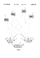
- FIG. 1 is a schematic view of an environment in which the invention can be used.
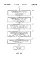
- FIGS. 2A/2B and 3A/3B are flow diagrams illustrating use of the invention in two embodiments.
- An SATPS mobile station 11 carries an SATPS signal antenna 13 and associated SATPS signal receiver/processor 15 and a mobile station downloader and associated port 18 (or transmitter and associated antenna) that are connected to the SATPS receiver/processor 15, in one embodiment of the invention shown in FIG. 1.
- the mobile station 11 receives SATPS signals from M ( ⁇ 4) SATPS satellites 21, 23, 25 and 27. Receipt of these signals allows the user to calculate the uncorrected, SATPS-determined present spatial location coordinates x unc , y unc , z unc and clock bias coordinate b unc , referred to as location fix coordinates (x,y,z,b) unc , of the SATPS antenna 13 in a selected coordinate system.
- the spatial location coordinates (x,y,z) may be expressed in any coordinate system and are not limited to a Cartesian system.
- the mobile station downloader 18 permits downloading (or transmission) of the uncorrected location fix coordinates (x,y,z,b) unc to an SATPS supplemental data processor station ("supplemental station") that may be spaced apart from the mobile station 11 and/or reference station 31 while these stations are collecting data, for subsequent processing by the supplemental station.
- supplemental station SATPS supplemental data processor station
- the location coordinates of the SATPS reference station 31 are known with high accuracy, through a survey or by other means, and the mobile station data and reference station data are downloaded to the supplemental station after the data are collected.
- relevant data obtained by the reference station 31 may be collected and downloaded to the mobile station 11, for subsequent processing by the mobile station.
- relevant data obtained by the reference station and by the mobile station may be collected downloaded for subsequent processing by the reference station 31.
- the reference station 31 also has an SATPS signal antenna 33 and SATPS signal receiver/processor 35 that receives and processes SATPS signals from the M SATPS satellites 21, 23, 25 and 27.
- the supplemental station 36 includes a downloading receiver and associated port 38 (or receiver and associated antenna) that receive signals from the mobile station downloader 18 and from a downloader 34 for the reference station 31. If the reference station 31 serves as the supplemental station 36, the downloader 34 is deleted.
- a nominal solution with location fix coordinates (x0,y0,z0,b0) is determined in some neighborhood of a location of interest (preferably within 100 km) with as yet unknown location fix coordinates (x,y,z,b), where the nominal solution approximately satisfies the pseudorange relations
- b0(t) is the computed but uncorrected clock bias for the nominal solution.
- the formalism used here is set forth by P. S. Jorgensen in "Navstar/Global Positioning System 18-satellite Constellations," Navigation, vol. 2, 1984, pp. 1-12, Appendix B.
- Equation (2) is rewritten in the form
- the matrix H(t f ;mob) is determined by the reference station (or by the mobile station, or by a third SATPS receiver/processor that receives downloaded data from the mobile station), using location fix coordinates determined at or near the estimated, uncorrected location of the mobile station. Normally, this will be done by (post-)processing at a supplemental station, after the necessary data are downloaded from the mobile station. If this processing is not done at the reference station, the reference station need only measure and (optionally) store the pseudorange signal values and determine the pseudorange corrections for these values.
- the location fix coordinates correction vector ⁇ W(t f ;mob) represents displacements of the location fix coordinates for the estimated location of the mobile station relative to the location fix coordinates for the location at which a nominal (uncorrected) solution is available and known.
- the vector PRC(t f ;mob) represents displacements of the uncorrected pseudorange values for the estimated location of the mobile station relative to the pseudorange values for the location at which the nominal solution is available and known.
- a pseudorange corrections vector PRC(t f ;ref) computed based on the known spatial location coordinates for the SATPS satellites, (x j (t f ),y j (t f ),z j (t f )) and for the reference station, is used for the mobile station pseudorange corrections vector PRC(t f ;mob).
- Methods for computing the entries of the vector PRC(t f ;ref) are well known in the art.
- Equation (5) relates the spatial location and clock bias corrections ( ⁇ x, ⁇ y, ⁇ z, ⁇ b) (to be determined; referred to collectively here as the "location fix coordinate corrections") to measurable or determinable differences in pseudorange parameters PRC(t f ;j;0) for the M satellites.
- the M ⁇ 4 matrix H(t f ;mob) relates the pseudorange corrections or innovations vector PRC(t f ;mob) to the location fix coordinate corrections ( ⁇ x, ⁇ y, ⁇ z, ⁇ b) relative to the nominal solution corrections.
- This matrix H(t f ;mob) is obtained from a first order expansion of the actual solution about the nominal solution and, therefore, provides approximate coordinate corrections.
- Other formalisms can be used here, but the form obtained for the resulting linearized relations is that of Eq. (5).
- the location fix coordinate values downloaded are chosen for efficiency, not necessarily for ease of computation.
- the spatial location coordinates of the mobile station 11 have modest dynamic ranges, such as a few hundred meters, because the spatial location changes relatively slowly, if at all.
- the clock bias coordinate if it is used, also has a limited dynamic range. Further, the total number (four or three) of these location fix coordinate values is manageable and can be stored in a memory as four (or three) double precision numerical values.
- the mobile station pseudorange values are to be stored and later downloaded to the reference station, the possible dynamic ranges are much larger; specification of the time coordinate requires sub-millisecond accuracy; and full range storage/downloading of the pseudorange values would probably require 4M double precision coordinate values for the satellites.
- 8 bytes are required for storage and downloading of the location fix coordinate values, and 4M bytes would be required for storage/downloading of the pseudorange values, with M>4.
- Storage/downloading of the index number (for example, 1-24) of each of the M SATPS satellites signals whose pseudorange measurements are used to determine the (uncorrected) location coordinates adds approximately 5M/8 bytes, whether the pseudoranges or the location coordinates are transmitted.
- the savings in number of bytes stored and downloaded is substantial.
- the uncorrected location fix coordinates (x,y,z,b) unc received from the mobile station are used to compute the matrix H(t f ;mob). Although these uncorrected coordinate values have inherent inaccuracies, these inaccuracies are likely to be relatively small (under 30 meters) and the entries for the matrix H(t f ;mob) are close to what should be used in Eq. (5) to relate the pseudorange corrections to the location fix corrections at the mobile station.
- Each of the four ordered columns of entries in H(t f ;mob) is also a vector in an expanded M-dimensional vector space S H* .
- the four-vector ⁇ W(t f ;mob) is extended to an M-vector ⁇ W*(t f ) that includes the original four-dimensional vectors that are part of the vector space S H .
- M-4 additional, linearly independent vectors can be found by the Gram-Schmidt orthogonalization process applied to the four M-entry column vectors of the H matrix, or by any other suitable process for vector space augmentation. The Gram-Schmidt orthogonalization process is discussed in R. Courant and D. Hilbert, Methods of Mathematical Physics, Interscience Publishers, New York, 1937, vol. 1, pp. 50-51.
- the matrix H(t f ;mob) becomes an augmented M ⁇ M matrix H*(t f ;mob) in the space S H* , with non-zero determinant.
- the matrix H*(t f ;mob) therefore, has an inverse, (H*(t f ;mob)) -1 in the space S H* , and one can set down an inverted form of Eq. (1) as
- Equation (14) is used by the supplemental station 36 to recover the coordinate value corrections ⁇ W*(t f ;mob) that would be computed at the mobile station's location, if the pseudorange corrections were available at that station.
- the mobile station uncorrected location fix coordinate values are then corrected by application of the pseudorange corrections, computed at the reference station 31 but using initial, uncorrected coordinate fix values computed for the estimated mobile station location.
- the corrected pseudorange values for the mobile station 11 are then used to determine the corrected location fix coordinates (x,y,z,b) of the mobile station according to the equation
- the matrix ⁇ W*(t f ;mob) contains the location fix coordinate corrections ( ⁇ x, ⁇ y, ⁇ z, ⁇ b) cor for the mobile station, together with M-4 other entries.
- the clock offset coordinate b can be ignored or discarded, because the location displacement due to provision of a realistic clock offset value b is estimated as at most 0.5 meters. If the clock offset coordinate b is ignored here, the location fix coordinate coordinate vector W(t f ;mob) becomes a 3 ⁇ 1 vector, which is extended by analogy with the above procedure to an M ⁇ 1 location fix coordinate matrix W*(t f ;mob) in a corresponding augmented M-dimensional space S H* of dimension M (M ⁇ 3).
- the location fix coordinate coordinate vector W(t f ;mob) becomes a 3 ⁇ 1 vector, containing only the coordinates x' and y', which is extended by analogy with the above procedure to an M ⁇ 1 location fix coordinate matrix W*(t f ;mob) in a corresponding augmented M-dimensional space S H* of dimension M (M>3).
- the satellite-nominal location distance r 0j (t f ) continues to be computed using Eq. (11).
- the entries in the corrected location fix coordinate matrix W*(t f ;mob) correspond to, and are interpretable as, the respective four corrected location fix coordinates x, y, z and b for the matrix W(t f ;mob).
- these four entries are the first four entries of the matrix W*(t f ;mob), and the first four entries of the M ⁇ 1 matrix W*(t f ;mob) in Eq. (15) become the corrected location fix coordinate values x, y, z and b.
- the reference station and the mobile station must agree on a format for these entries, and the supplemental station must receive the uncorrected location fix coordinates in an agreed order, such as x, y, z, b, or some other order. It is preferable, but not necessary, that all mobile stations transmit their uncorrected coordinate measurements (location coordinates and clock bias) in the same order.
- each entry in the matrix PRC(t f ;mob) corresponds to a different satellite.
- One suitable order which must be agreed upon by the mobile station and the reference station, is to arrange the "fundamental set" of satellites (the "best" minimum set, usually four, needed to determine DSATPS corrections for the reference station, or for the mobile station) in decreasing order of whatever SATPS signal quality parameter ⁇ is used to determine this best set of satellites, then arrange the entries in the matrix PRC(t f ;mob) for the remaining in-view satellites in decreasing order of the parameter ⁇ .
- Another approach is to arrange the fundamental set of satellites as set forth in the first approach, then arrange the entries for the remaining in-view satellites in an increasing or decreasing sequence for the satellite number.
- Many alternative approaches can be used here.
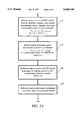
- the reference station and the mobile station should agree on the quality parameter ⁇ or other criterion to be used for this ordering. This method can be implemented as illustrated in FIG. 2.
- the reference station receives the SATPS signals from the same M SATPS satellites and determines the M ⁇ 1 pseudorange correction matrix PRC(t n ;ref) for these measurements for the reference station, using the known reference station coordinates.
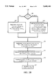
- the supplemental station determines the M ⁇ 1 coordinate value corrections matrix ⁇ W*(t n ;mob) for the mobile station, using Eq. (14), and the corrected location fix coordinates (x n ,y n ,z n ,b n ) cor for the mobile station according to Eq. (15), and (preferably) stores these quantities.
- step 155 the time index n is incremented (n ⁇ *n+1) and the reference station system returns to step 146 at least once.
- the steps 141-155 are easily modified to handle a situation where only the coordinates (x,y,z) or (x,y) are to be corrected.
- the M ⁇ 4 matrix H(t f ;mob) can be generalized to an M ⁇ N matrix with 2 ⁇ N ⁇ M that relates M pseudorange values and other observables to N spatial and/or time coordinates.
- the N-dimensional space S H of M-dimensional vectors is embedded in, or expanded to, an M-dimensional space S H* , using a Gram-Schmidt orthogonalization procedure or some other suitable procedure that produces M independent vectors, beginning with the subspace S H of S H* .
- N 3 for determination of two spatial coordinates three spatial coordinates.
- the matrix H(t f ;mob) tr H(t f ;mob) is a 4 ⁇ 4 (or 3 ⁇ 3) matrix and is invertible so that Eq. (17) is well defined.
- the quasi-inverse H(t f ;mob).sup.(-1) definition in Eq. (17) may also be recovered using an ordinary (uniformly weighted) least squares approach to the solution of Eq. (5).
- the procedural steps illustrated in FIGS. 2A/2B apply as before.
- the first P entries in the vector v correspond to pseudorange signals from the four satellites in the "fundamental set," for which a selected quality parameter ⁇ for each of these satellite signals is higher than the ⁇ values for any of the other in-view satellites (in the "non-fundamental set”).
- the quality parameter ⁇ may be chosen to be the geometrical dilution of precision (GDOP) for the configuration of these P satellites; or ⁇ may be chosen on some other basis.
- the known matrix H tr is similarly divided into a P ⁇ P sub-matrix H f tr and an (M-P) ⁇ P sub-matrix H nf tr , in the following manner.
- the entries in the (M ⁇ P) ⁇ 1 matrix or vector v nf correspond to the pseudorange corrections for the non-fundamental set of SATPS satellites and are constructed from Eq. (18).
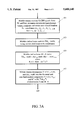
- the non-fundamental set v nf of pseudorange data plus the uncorrected coordinates (x n ,y n ,z n ,b n ) unc (with z n and/or b n optionally deleted) are downloaded by the mobile station to the supplemental station, together with a set ⁇ of indicia indicating which satellites are included in the fundamental set and in the non-fundamental set.
- the vector v can be used to construct parity vectors and other useful measures of accuracy.
- the mobile station uncorrected pseudorange values are constructed, using the received mobile station coordinates (x n ,y n ,z n ,b n ) unc , and can be corrected using the reference station pseudorange corrections PRC(t n ;j;ref).
- This approach does not require construction of an augmented vector space S H* or construction of an inverse matrix H*(t f ;mob) -1 .
- the original M ⁇ P matrix H(t f ;mob) is divided into a P ⁇ P matrix H f and an (M-P) ⁇ P matrix H nf , an inverse matrix (H f tr ) -1 is formed, the matrix (H f tr ) -1 H nf tr is formed, and the fundamental set P-vector v f is reconstructed at the reference station from the usually-fewer set of entries v nf , using Eq. (22).
- the vector v is divided into a fundamental set vector v f and a non-fundamental set vector v nf .
- the entries for the non-fundamental set vector v nf are transmitted to the reference station, along with the fundamental set indicia ⁇ .
- step 171 the fundamental set vector v f is reconstructed using Eq. (20).
- the mobile station pseudorange values are reconstructed from the vector components of v f and/or v nf , in step 173.
- Equation (14) explicitly uses the pseudorange corrections matrix, PRC(t f ;mob), and the inverse of the augmented H matrix, H*(t f ;mob), to compute the augmented location fix coordinate corrections matrix ⁇ W*(t f ;mob).
- This formulation allows use of SATPS almanac data, which is changed once or twice per week, or use of SATPS ephemerides data, which is changed once every 1-4 hours and is more accurate than the almanac data.
- Ionocorr* is an M ⁇ 1 whose entries are the computed or modeled ionospheric time delay corrections for SATPS signal propagation from each of the M satellites
- Tropocorr* is an M ⁇ 1 matrix whose entries are the computed or modeled tropospheric time delay corrections for SATPS signal propagation from each of the M satellites.
- the preceding development may be characterized in the following manner.
- the differences in corrected pseudorange values ⁇ z between the mobile station (z) and the reference station (z 0 ) is related to the differences in corrected location fix coordinate values ⁇ x between the mobile station (x) and the reference station (x 0 ) by the relation
- z 0 is an M ⁇ 1 vector representing the corrected pseudorange values at the reference station and x 0 is a 4 ⁇ 1 (or 3 ⁇ 1) vector representing the corrected location fix coordinates for the reference station.
- ⁇ z u between the corrected reference station pseudorange values (z 0 ) and the uncorrected reference station pseudorange values (z 0 u ) is given by
- the corrected pseudorange values vector for the mobile station is here taken to be
- an uncorrected location fix coordinates vector x.sup. ⁇ u for the mobile station is related to the known (and a fortiori correct) location fix coordinates vector x 0 for the reference station by the relations
- a Satellite Positioning System is a system of satellite signal transmitters, with receivers located on the Earth's surface or adjacent to the Earth's surface, that transmits information from which an observer's present location and/or the time of observation can be determined.
- Two operational systems, each of which qualifies as an SATPS, are the Global Positioning System and the Global Orbiting Navigational System.
- GPS Global Positioning System
- a fully operational GPS includes up to 24 satellites approximately uniformly dispersed around six circular orbits with four satellites each, the orbits being inclined at an angle of 55° relative to the equator and being separated from each other by multiples of 60° longitude.
- the orbits have radii of 26,560 kilometers and are approximately circular.
- the orbits are non-geosynchronous, with 0.5 sidereal day (11.967 hours) orbital time intervals, so that the satellites move with time relative to the Earth below.
- GPS satellites will be visible from most points on the Earth's surface, and visual access to two or more such satellites can be used to determine an observer's position anywhere on the Earth's surface, 24 hours per day.
- Each satellite carries a cesium or rubidium atomic clock to provide timing information for the signals transmitted by the satellites. Internal clock correction is provided for each satellite clock.
- the L1 signal from each satellite is binary phase shift key (BPSK) modulated by two pseudo-random noise (PRN) codes in phase quadrature, designated as the C/A-code and P-code.
- PRN pseudo-random noise
- the L2 signal from each satellite is BPSK modulated by only the P-code. The nature of these PRN codes is described below.
- PRN codes allows use of a plurality of GPS satellite signals for determining an observer's position and for providing navigation information.
- a signal transmitted by a particular GPS signal is selected by generating and matching, or correlating, the PRN code for that particular satellite.
- All PRN codes are known and are generated or stored in GPS satellite signal receivers carried by ground observers.
- the C/A-code for any GPS satellite has a length of 1023 chips or time increments before this code repeats.
- the full P-code has a length of 259 days, with each satellite transmitting a unique portion of the full P-code.
- the portion of P-code used for a given GPS satellite has a length of precisely one week (7.000 days) before this code portion repeats.
- Accepted methods for generating the C/A-code and P-code are set forth in the document GPS Interface Control Document ICD-GPS-200, published by Rockwell International Corporation, Satellite Systems Division, Revision B, July 1991, which is incorporated by reference herein.
- the GPS satellite bit stream includes navigational information on the ephemeris of the transmitting GPS satellite and an almanac for all GPS satellites, with parameters providing corrections for ionospheric signal propagation delays suitable for single frequency receivers and for an offset time between satellite clock time and true GPS time.
- the navigational information is transmitted at a rate of 50 Baud.
- GLONASS Global Orbiting Navigation Satellite System
- GLONASS Global Orbiting Navigation Satellite System
- GLONASS also uses 24 satellites, distributed approximately uniformly in three orbital planes of eight satellites each. Each orbital plane has a nominal inclination of 64.8° relative to the equator, and the three orbital planes are separated from each other by multiples of 120° longitude.
- the GLONASS circular orbits have smaller radii, about 25,510 kilometers, and a satellite period of revolution of 8/17 of a sidereal day (11.26 hours).
- a GLONASS satellite and a GPS satellite will thus complete 17 and 16 revolutions, respectively, around the Earth every 8 days.
- the L2 code is presently modulated only by the P-code.
- the GLONASS satellites also transmit navigational data at at rate of 50 Baud. Because the channel frequencies are distinguishable from each other, the P-code is the same, and the C/A-code is the same, for each satellite.
- the methods for receiving and analyzing the GLONASS signals are similar to the methods used for the GPS signals.
- Reference to a Satellite Positioning System or SATPS herein refers to a Global Positioning System, to a Global Orbiting Navigation System, and to any other compatible satellite-based system that provides information by which an observer's position and the time of observation can be determined, all of which meet the requirements of the present invention.
- a Satellite Positioning System such as the Global Positioning System (GPS) or the Global Orbiting Navigation Satellite System (GLONASS) uses transmission of coded radio signals, with the structure described above, from a plurality of Earth-orbiting satellites.
- GPS Global Positioning System
- GLONASS Global Orbiting Navigation Satellite System
- a single passive receiver of such signals is capable of determining receiver absolute position in an Earth-centered, Earth-fixed coordinate reference system utilized by the SATPS.
- a configuration of two or more receivers can be used to accurately determine the relative positions between the receivers or stations.
- This method known as differential positioning, is far more accurate than absolute positioning, provided that the distances between these stations are substantially less than the distances from these stations to the satellites, which is the usual case.
- Differential positioning can be used for survey or construction work in the field, providing location coordinates and distances that are accurate to within a few centimeters.
- An SATPS antenna receives SATPS signals from a plurality (preferably four or more) of SATPS satellites and passes these signals to an SATPS signal receiver/processor, which (1) identifies the SATPS satellite source for each SATPS signal, (2) determines the time at which each identified SATPS signal arrives at the antenna, and (3) determines the present location of the SATPS antenna from this information and from information on the ephemerides for each identified SATPS satellite.
- the SATPS signal antenna and signal receiver/processor are part of the user segment of a particular SATPS, the Global Positioning System, as discussed by Tom Logsdon in The NAVSTAR Global Positioning System, Van Nostrand Reinhold, 1992, op cit.
Abstract
Description
{(x0-x.sub.j (t.sub.f)).sup.2 +(y0-y.sub.j (t.sub.f)).sup.2 +(z0-z.sub.j (t.sub.f)).sup.2 }.sup.1/2 +b0==PR(t.sub.f ;j;nom), (1)
{(x-x.sub.j (t.sub.f)).sup.2 +(y-y.sub.j (t.sub.f)).sup.2 +(z-z.sub.j (t.sub.f)).sup.2 }.sup.1/2 +b==PR(t.sub.f ;j;S), (2)
{(x-x0+x0-x.sub.j (t.sub.f)).sup.2 +(y-y0+y0-y.sub.j (t.sub.f)).sup.2 +(z-z0+z0-z.sub.j (t.sub.f)).sup.2 }.sup.1/2+ b0+(b-b0)=PR(t.sub.f ;j;nom)+PRC(t.sub.f ;j;nom), (3)
PRC(t.sub.f ;j;nom)=PR(t.sub.f ;j;S)-PR(t.sub.f ;j;nom), (4)
H(t.sub.f ;mob) ΔW(t.sub.f ;mob)=PRC(t.sub.f ;mob), (5)
H(t.sub.f ;mob)=(h.sub.ji (t.sub.f)), (6)
h.sub.j1 (t.sub.f)=α.sub.j1 (t.sub.f)=(x0-x.sub.j (t.sub.f))/r.sub.0j,(7)
h.sub.j2 (t.sub.f)=α.sub.j2 (t.sub.f)=(y0-y.sub.j (t.sub.f))/r.sub.0j,(8)
h.sub.j3 (t.sub.f)=α.sub.j3 (t.sub.f)=(z0-z.sub.j (t.sub.f))/r.sub.0j,(9)
h.sub.j4 (t.sub.f)=1, (i=1, 2, 3, . . . , M), (10)
r.sub.0j (t.sub.f)={(x0-x.sub.j (t.sub.f)).sup.2 +(y0-y.sub.j (t.sub.f)).sup.2 +(z0-z.sub.j (t.sub.f)).sup.2 }.sup.1/2, (11)
ΔW(t.sub.f ;mob).sup.tr =W(t.sub.f ;mob).sup.tr -W0.sup.tr = Δx Δy Δz Δb!.sup.tr, (12)
PRC(t.sub.f ;mob).sup.tr = PRC(t.sub.f ;1;mob) . . . PRC(t.sub.f ;M;mob)!.(13)
ΔW*(t.sub.f ;mob)=H*(t.sub.f ;mob).sup.-1 PRC(t.sub.f ;mob),(14)
W*(t.sub.f ;mob)=W*(t.sub.f ;mob).sub.unc +ΔW*(t.sub.f ;mob)=W*(t.sub.f ;mob).sub.unc +H*(t.sub.f ;mob).sup.-1 PRC(t.sub.f ;mob),(15)
ΔW*(t.sub.f ;mob)=H(t.sub.f ;mob).sup.(-1) PRC(t.sub.f ;mob),(16)
H(t.sub.f ;mob).sup.(-1) =(H(t.sub.f ;mob).sup.tr H(t.sub.f ;mob)).sup.-1 H(t.sub.f ;mob).sup.tr. (17)
H.sup.tr v(t.sub.f ;mob)=H.sup.tr K(t.sub.f ;mob)PR(t.sub.f ;mob)=0.(19)
v= v.sub.f |v.sub.nf !.sup.tr. (20)
H.sup.tr = H.sub.f.sup.tr |H.sub.nf.sup.tr !, (21)
v.sub.f =-(H.sub.f.sup.tr).sup.-1 H.sub.nf.sup.tr v.sub.nf.(22)
z-z.sub.0 =H(t.sub.f ;mob)(x-x.sub.0), (25)
Δz.sup.u =z.sup.u -z.sub.0. (26)
z=z.sup.u +PRC(t.sub.f ;mob)≈z.sup.u +PRC(t.sub.f ;ref).(27)
x.sup.Λu =H(t.sub.f ;mob).sup.-1 Δz.sup.u +x.sub.0.(28)
Claims (42)
H(t.sub.f ;mob)=(h.sub.ji (t.sub.f)),
h.sub.j1 (t.sub.f)=α.sub.j1 (t.sub.f)=(x'(t.sub.f)-x.sub.j (t.sub.f))/r.sub.0j (t.sub.f),
h.sub.j2 (t.sub.f)=α.sub.j2 (t.sub.f)=(y'(t.sub.f)-y.sub.j (t.sub.f))/r.sub.0j (t.sub.f),
h.sub.j3 (t.sub.f)=α.sub.j3 (t.sub.f)=(z'(t.sub.f)-z.sub.j (t.sub.f))/r.sub.0j (t.sub.f),
h.sub.j4 (t.sub.f)=1, (j=1, 2, . . . , M),
r.sub.0j (t.sub.f)= (x'(t.sub.f)-x.sub.j (t.sub.f)).sup.2 +(y'(t.sub.f)-y.sub.j (t.sub.f)).sup.2 +(z'(t.sub.f)-z.sub.j (t.sub.f)).sup.2 !.sup.1/2 ;
x(t.sub.f)=x'(t.sub.f)+Δw.sub.1 (t.sub.f),
y(t.sub.f)=y'(t.sub.f)+Δw.sub.2 (t.sub.f),
z(t.sub.f)=z'(t.sub.f)+Δw.sub.3 (t.sub.f),
b(t.sub.f)=b'(t.sub.f)+Δw.sub.4 (t.sub.f).
H(t.sub.f ;mob).sup.Λ =(H(t.sub.f ;mob).sup.tr H(t.sub.f ;mob)).sup.-1 H(t.sub.f ;mob).sup.tr.
H(t.sub.f ;mob)=(h.sub.ji (t.sub.f)),
h.sub.j1 (t.sub.f)=α.sub.j1 (t.sub.f)=(x'(t.sub.f)-x.sub.j (t.sub.f))/r.sub.0j (t.sub.f),
h.sub.j2 (t.sub.f)=α.sub.j2 (t.sub.f)=(y'(t.sub.f)-y.sub.j (t.sub.f))/r.sub.0j (t.sub.f),
h.sub.j3 (t.sub.f)=α.sub.j3 (t.sub.f)=(z'(t.sub.f)-z.sub.j (t.sub.f))/r.sub.0j (t.sub.f), (j=1, 2, . . . , M),
r.sub.0j (t.sub.f)= (x'(t.sub.f)-x.sub.j (t.sub.f)).sup.2 +(y'(t.sub.f)-y.sub.j (t.sub.f)).sup.2 +(z'(t.sub.f)-z.sub.j (t.sub.f)).sup.2 !.sup.1/2 ;
x(t.sub.f)=x'(t.sub.f)+Δw.sub.1 (t.sub.f),
y(t.sub.f)=y'(t.sub.f)+Δw.sub.2 (t.sub.f),
z(t.sub.f)=z'(t.sub.f)+Δw.sub.3 (t.sub.f).
H(t.sub.f ;mob).sup.Λ =(H(t.sub.f ;mob).sup.tr H(t.sub.f ;mob)).sup.-1 H(t.sub.f ;mob).sup.tr.
H(t.sub.f ;mob)=(h.sub.ji (t.sub.f)),
h.sub.j1 (t.sub.f)=α.sub.j1 (t.sub.f)=(x'(t.sub.f)-x.sub.j (t.sub.f))/r.sub.0j (t.sub.f),
h.sub.j2 (t.sub.f)=α.sub.j2 (t.sub.f)=(y'(t.sub.f)-y.sub.j (t.sub.f))/r.sub.0j (t.sub.f),
h.sub.j3 (t.sub.f)=α.sub.j3 (t.sub.f)=(z'(t.sub.f)-z.sub.j (t.sub.f))/r.sub.0j (t.sub.f) (j=1, 2, . . . , M),
r.sub.0j (t.sub.f)= (x'(t.sub.f)-x.sub.j (t.sub.f)).sup.2 +(y'(t.sub.f)-y.sub.j (t.sub.f)).sup.2 +(z'(t.sub.f)-z.sub.j (t.sub.f)).sup.2 !.sup.1/2 ;
x(t.sub.f)=x'(t.sub.f)+Δw.sub.1 (t.sub.f),
y(t.sub.f)=y'(t.sub.f)+Δw.sub.2 (t.sub.f),
z(t.sub.f)=z'(t.sub.f).
H(t.sub.f ;mob).sup.Λ =(H(t.sub.f ;mob).sup.tr H(t.sub.f ;mob)).sup.-1 H(t.sub.f ;mob).sup.tr.
H(t.sub.f ;mob)=(h.sub.ji (t.sub.f)),
h.sub.j1 (t.sub.f)=α.sub.j1 (t.sub.f)=(x'(t.sub.f)-x.sub.j (t.sub.f))/r.sub.0j (t.sub.f),
h.sub.j2 (t.sub.f)=α.sub.j2 (t.sub.f)=(y'(t.sub.f)-y.sub.j (t.sub.f))/r.sub.0j (t.sub.f),
h.sub.j3 (t.sub.f)=α.sub.j3 (t.sub.f)=(z'(t.sub.f)-z.sub.j (t.sub.f))/r.sub.0j (t.sub.f),
h.sub.j4 (t.sub.f)=1, (j=1, 2, . . . , M),
r.sub.0j (t.sub.f)- (x'(t.sub.f)-x.sub.j (t.sub.f)).sup.2 +(y'(t.sub.f)-y.sub.j (t.sub.f)).sup.2 +(z'(t.sub.f)-z.sub.j (t.sub.f)).sup.2 !.sup.1/2 ;
H(t.sub.f ;mob)=(h.sub.ji (t.sub.f)),
h.sub.j1 (t.sub.f)=α.sub.j1 (t.sub.f)=(x'(t.sub.f)-x.sub.j (t.sub.f))/r.sub.0j (t.sub.f),
h.sub.j2 (t.sub.f)=α.sub.j2 (t.sub.f)=(y'(t.sub.f)-y.sub.j (t.sub.f))/r.sub.0j (t.sub.f),
h.sub.j3 (t.sub.f)=α.sub.j3 (t.sub.f)=(z'(t.sub.f)-z.sub.j (t.sub.f))/r.sub.0j (t.sub.f), (j=1, 2, . . . , M),
r.sub.0j (t.sub.f)= (x'(t.sub.f)-x.sub.j (t.sub.f)).sup.2 +(y'(t.sub.f)-y'(t.sub.f)).sup.2 !.sup.1/2.
H(t.sub.f ;mob)=(h.sub.ji (t.sub.f)),
h.sub.j1 (t.sub.f)=α.sub.j1 (t.sub.f)=(x'(t.sub.f)-x.sub.j (t.sub.f))/r.sub.0j (t.sub.f),
h.sub.j2 (t.sub.f)=α.sub.j2 (t.sub.f)=(y'(t.sub.f)-y.sub.j (t.sub.f))/r.sub.0j (t.sub.f),
h.sub.j3 (t.sub.f)=α.sub.j3 (t.sub.f)=(z'(t.sub.f)-z.sub.j (t.sub.f))/r.sub.0j (t.sub.f), (j=1, 2, . . . , M),
r.sub.0j (t.sub.f)= (x'(t.sub.f)-x.sub.j (t.sub.f)).sup.2 +(y'(t.sub.f)-y.sub.j (t.sub.f)).sup.2 +(z'(t.sub.f)-z.sub.j (t.sub.f))2!.sup.-1/2 ;
H(t.sub.f ;mob)=(h.sub.ji (t.sub.f)),
h.sub.j1 (t.sub.f)=α.sub.j1 (t.sub.f)=(x'(t.sub.f)-x.sub.j (t.sub.f))/r.sub.0j (t.sub.f),
h.sub.j2 (t.sub.f)=α.sub.j2 (t.sub.f)=(y'(t.sub.f)-y.sub.j (t.sub.f))/r.sub.0j (t.sub.f),
h.sub.j3 (t.sub.f)=α.sub.j3 (t.sub.f)=(z'(t.sub.f)-z.sub.j (t.sub.f))/r.sub.0j (t.sub.f),
h.sub.j4 (t.sub.f)=1, (j=1, 2, . . . , M),
r.sub.0j (t.sub.f)= (x'(t.sub.f)-x.sub.j (t.sub.f)).sup.2 +(y'(t.sub.f)-y'(t.sub.f)).sup.2 +(z'(t.sub.f)-z.sub.j (t.sub.f)).sup.2 !.sup.1/2 ;
x(t.sub.f)=x'(t.sub.f)+Δw.sub.1 (t.sub.f),
y(t.sub.f)=y'(t.sub.f)+Δw.sub.2 (t.sub.f),
z(t.sub.f)=z'(t.sub.f)+Δw.sub.3 (t.sub.f),
b(t.sub.f)=b'(t.sub.f)+Δw.sub.4 (t.sub.f).
H(t.sub.f ;mob).sup.Λ =(H(t.sub.f ;mob).sup.tr H(t.sub.f ;mob)).sup.-1 H(t.sub.f ;mob).sup.tr.
H(t.sub.f ;mob)=(h.sub.ji (t.sub.f)),
h.sub.j1 (t.sub.f)=α.sub.j1 (t.sub.f)=(x'(t.sub.f)-x.sub.j (t.sub.f))/r.sub.0j (t.sub.f),
h.sub.j2 (t.sub.f)=α.sub.j2 (t.sub.f)=(y'(t.sub.f)-y.sub.j (t.sub.f))/r.sub.0j (t.sub.f),
h.sub.j3 (t.sub.f)=α.sub.j3 (t.sub.f)=(z'(t.sub.f)-z.sub.j (t.sub.f))/r.sub.0j (t.sub.f), (j=1, 2, . . . , M),
r.sub.0j (t.sub.f)= (x'(t.sub.f)-x.sub.j (t.sub.f)).sup.2 +(y'(t.sub.f)-y.sub.j (t.sub.f)).sup.2 +(z'(t.sub.f)-z.sub.j (t.sub.f)).sup.2 !.sup.1/2 ;
x(t.sub.f)=x'(t.sub.f)+Δw.sub.1 (t.sub.f),
y(t.sub.f)=y'(t.sub.f)+Δw.sub.2 (t.sub.f),
z(t.sub.f)=z'(t.sub.f)+Δw.sub.3 (t.sub.f).
H(t.sub.f ;mob).sup.Λ =(H(t.sub.f ;mob).sup.tr H(t.sub.f ;mob)).sup.-1 H(t.sub.f ;mob).sup.tr.
H(t.sub.f ;mob)=(h.sub.ji (t.sub.f)),
h.sub.j1 (t.sub.f)=α.sub.j1 (t.sub.f)=(x'(t.sub.f)-x.sub.j (t.sub.f))/r.sub.0j (t.sub.f),
h.sub.j2 (t.sub.f)=α.sub.j2 (t.sub.f)=(y'(t.sub.f)-y.sub.j (t.sub.f))/r.sub.0j (t.sub.f),
h.sub.j3 (t.sub.f)=α.sub.j3 (t.sub.f)=(z'(t.sub.f)-z.sub.j (t.sub.f))/r.sub.0j (t.sub.f) (j=1, 2, . . . , M),
r.sub.0j (t.sub.f)= (x'(t.sub.f)-x.sub.j (t.sub.f)).sup.2 +(y'(t.sub.f)-y.sub.j (t.sub.f)).sup.2 +(z'(t.sub.f)-z.sub.j (t.sub.f)).sup.2 !.sup.1/2 ;
x(t.sub.f)=x'(t.sub.f)+Δw.sub.1 (t.sub.f),
y(t.sub.f)=y'(t.sub.f)+Δw.sub.2 (t.sub.f),
z(t.sub.f)=z'(t.sub.f).
H(t.sub.f ;mob).sup.Λ =(H(t.sub.f ;mob).sup.tr H(t.sub.f ;mob)).sup.-1 H(t.sub.f ;mob).sup.tr.
H(t.sub.f ;mob)=(h.sub.ji (t.sub.f)),
h.sub.j1 (t.sub.f)=α.sub.j1 (t.sub.f)=(x'(t.sub.f)-x.sub.j (t.sub.f))/r.sub.0j (t.sub.f),
h.sub.j2 (t.sub.f)=α.sub.j2 (t.sub.f)=(y'(t.sub.f)-y.sub.j (t.sub.f))/r.sub.0j (t.sub.f),
h.sub.j3 (t.sub.f)=α.sub.j3 (t.sub.f)=(z'(t.sub.f)-z.sub.j (t.sub.f))/r.sub.0j (t.sub.f),
h.sub.j4 (t.sub.f)=1, (j=1, 2, . . . , M),
r.sub.0j (t.sub.f)= (x'(t.sub.f)-x.sub.j (t.sub.f)).sup.2 +(y'(t.sub.f)-y.sub.j (t.sub.f)).sup.2 +(z'(t.sub.f)-z.sub.j (t.sub.f)).sup.2 !.sup.1/2 ;
H(t.sub.f ;mob)-(h.sub.ji (t.sub.f)),
h.sub.j1 (t.sub.f)=α.sub.j1 (t.sub.f)=(x'(t.sub.f)-x.sub.j (t.sub.f))/r.sub.0j (t.sub.f),
h.sub.j2 (t.sub.f)=α.sub.j2 (t.sub.f)=(y'(t.sub.f)-y.sub.j (t.sub.f))/r.sub.0j (t.sub.f),
h.sub.j3 (t.sub.f)=α.sub.j3 (t.sub.f)=(z'(t.sub.f)-z.sub.j (t.sub.f))/r.sub.0j (t.sub.f), (j=1, 2, . . . , M),
r.sub.0j (t.sub.f)= (x'(t.sub.f)-x.sub.j (t.sub.f)).sup.2 +(y'(t.sub.f)-y.sub.j (t.sub.f)).sup.2 +(z'(t.sub.f)-z.sub.j (t.sub.f)).sup.2 !.sup.1/2 ;
H(t.sub.f ;mob)=(h.sub.ji (t.sub.f)),
h.sub.j1 (t.sub.f)=α.sub.j1 (t.sub.f)=(x'(t.sub.f)-x.sub.j (t.sub.f))/r.sub.0j (t.sub.f),
h.sub.j2 (t.sub.f)=α.sub.j2 (t.sub.f)=(y'(t.sub.f)-y.sub.j (t.sub.f))/r.sub.0j (t.sub.f),
h.sub.j3 (t.sub.f)=α.sub.j3 (t.sub.f)=(z'(t.sub.f)-z.sub.j (t.sub.f))/r.sub.0j (t.sub.f), (j=1, 2, . . . , M),
r.sub.0j (t.sub.f)= (x'(t.sub.f)-x.sub.j (t.sub.f)).sup.2 +(y'(t.sub.f)-y.sub.j (t.sub.f)).sup.2 +(z'(t.sub.f)-z.sub.j (t.sub.f)).sup.2 !.sup.1/2 ;
Priority Applications (2)
| Application Number | Priority Date | Filing Date | Title |
|---|---|---|---|
| US08/607,176 US5680140A (en) | 1994-07-19 | 1996-02-26 | Post-processing of inverse differential corrections for SATPS mobile stations |
| US08/954,645 US6014101A (en) | 1996-02-26 | 1997-10-20 | Post-processing of inverse DGPS corrections |
Applications Claiming Priority (2)
| Application Number | Priority Date | Filing Date | Title |
|---|---|---|---|
| US08/277,149 US5495257A (en) | 1994-07-19 | 1994-07-19 | Inverse differential corrections for SATPS mobile stations |
| US08/607,176 US5680140A (en) | 1994-07-19 | 1996-02-26 | Post-processing of inverse differential corrections for SATPS mobile stations |
Related Parent Applications (1)
| Application Number | Title | Priority Date | Filing Date |
|---|---|---|---|
| US08/277,149 Continuation-In-Part US5495257A (en) | 1994-07-19 | 1994-07-19 | Inverse differential corrections for SATPS mobile stations |
Related Child Applications (1)
| Application Number | Title | Priority Date | Filing Date |
|---|---|---|---|
| US08/954,645 Continuation US6014101A (en) | 1996-02-26 | 1997-10-20 | Post-processing of inverse DGPS corrections |
Publications (1)
| Publication Number | Publication Date |
|---|---|
| US5680140A true US5680140A (en) | 1997-10-21 |
Family
ID=46250949
Family Applications (1)
| Application Number | Title | Priority Date | Filing Date |
|---|---|---|---|
| US08/607,176 Expired - Fee Related US5680140A (en) | 1994-07-19 | 1996-02-26 | Post-processing of inverse differential corrections for SATPS mobile stations |
Country Status (1)
| Country | Link |
|---|---|
| US (1) | US5680140A (en) |
Cited By (81)
| Publication number | Priority date | Publication date | Assignee | Title |
|---|---|---|---|---|
| US5825328A (en) * | 1997-01-11 | 1998-10-20 | Trimble Navigation Limited | Precise inverse differential corrections for location determination |
| US5831576A (en) * | 1994-06-02 | 1998-11-03 | Trimble Navigation Limited | Integrity monitoring of location and velocity coordinates from differential satellite positioning systems signals |
| WO1999047943A1 (en) * | 1998-03-17 | 1999-09-23 | Qualcomm Incorporated | System and method for determining the position of a wireless cdma transceiver |
| WO1999053338A2 (en) * | 1998-04-16 | 1999-10-21 | Snaptrack, Inc. | Method and apparatus for determining time in a satellite positioning system |
| US5973639A (en) * | 1997-09-23 | 1999-10-26 | Trimble Navigation Limited | Global positioning system having postprocessed realtime corrected data |
| US5999878A (en) * | 1997-04-11 | 1999-12-07 | Navigation Technologies Corp. | System and method for acquiring geographic data for forming a digital database of road geometry in a geographic region |
| US6014101A (en) * | 1996-02-26 | 2000-01-11 | Trimble Navigation Limited | Post-processing of inverse DGPS corrections |
| US6049304A (en) * | 1997-07-10 | 2000-04-11 | Rannoch Corporation | Method and apparatus for improving the accuracy of relative position estimates in a satellite-based navigation system |
| US6083248A (en) * | 1995-06-23 | 2000-07-04 | Medtronic, Inc. | World wide patient location and data telemetry system for implantable medical devices |
| US6111541A (en) * | 1997-05-09 | 2000-08-29 | Sony Corporation | Positioning system using packet radio to provide differential global positioning satellite corrections and information relative to a position |
| US6219544B1 (en) * | 1995-12-20 | 2001-04-17 | Nokia Telecommunications Oy | Telemetric measuring of a mobile telephone network |
| US20010041535A1 (en) * | 1997-05-09 | 2001-11-15 | Karmel Clayton R. | Positioning system using packet radio to determine position and to obtain information relative to a position |
| US6384783B1 (en) | 1998-07-14 | 2002-05-07 | Rannoch Corporation | Method and apparatus for correlating flight identification data with secondary surveillance |
| US6397147B1 (en) * | 2000-06-06 | 2002-05-28 | Csi Wireless Inc. | Relative GPS positioning using a single GPS receiver with internally generated differential correction terms |
| US6448929B1 (en) | 1998-07-14 | 2002-09-10 | Rannoch Corporation | Method and apparatus for correlating flight identification data with secondary surveillance radar data |
| US6567043B2 (en) | 1999-03-05 | 2003-05-20 | Rannoch Corporation | Method and apparatus for improving utility of automatic dependent surveillance |
| US6618004B2 (en) | 2000-05-08 | 2003-09-09 | Novatel, Inc. | Precise positioning system for mobile GPS users |
| FR2836997A1 (en) * | 2002-03-08 | 2003-09-12 | Thales Sa | METHOD AND DEVICE FOR DETERMINING THE RELATIVE POSITION OF TWO POINTS, BASED ON SATELLITE POSITIONING SIGNALS |
| US6658353B2 (en) * | 2000-11-08 | 2003-12-02 | Denso Corporation | Vehicle navigation apparatus providing rapid correction for excessive error in dead reckoning estimates of vehicle travel direction by direct application of position and direction information derived from gps position measurement data |
| US6741863B1 (en) * | 1998-12-18 | 2004-05-25 | Lucent Technologies Inc. | Method and apparatus for locating a wireless mobile unit |
| US20040189521A1 (en) * | 1999-03-05 | 2004-09-30 | Smith Alexander E. | Method and apparatus for accurate aircraft and vehicle tracking |
| US6812890B2 (en) | 2000-02-29 | 2004-11-02 | Rannoch Corporation | Voice recognition landing fee billing system |
| US20040222916A1 (en) * | 1999-03-05 | 2004-11-11 | Smith Alexander E. | Minimum safe altitude warning |
| US20040246178A1 (en) * | 1999-03-05 | 2004-12-09 | Smith Alexander E. | Method and apparatus to correlate aircraft flight tracks and events with relevant airport operations information |
| US20040257277A1 (en) * | 2003-06-17 | 2004-12-23 | Global Locate Inc. | Method and apparatus for locating position of a satellite signal receiver |
| US20050007272A1 (en) * | 2000-02-29 | 2005-01-13 | Smith Alexander E. | Correlation of flight track data with other data sources |
| US20060036378A1 (en) * | 1999-03-05 | 2006-02-16 | Smith Alexander E | Airport pavement management system |
| US20060085236A1 (en) * | 1999-03-05 | 2006-04-20 | Smith Alexander E | Automated management of airport revenues |
| US20070001903A1 (en) * | 1999-03-05 | 2007-01-04 | Smith Alexander E | Use of geo-stationary satellites to augment wide_area multilateration synchronization |
| US20070040734A1 (en) * | 1999-03-05 | 2007-02-22 | Evers Carl A | Method and system for elliptical-based surveillance |
| US20080191942A1 (en) * | 1999-03-05 | 2008-08-14 | Smith Alexander E | Method and apparatus to extend ads performance metrics |
| US7423590B2 (en) | 1999-03-05 | 2008-09-09 | Era Systems Corporation | Method and apparatus for improving ADS-B security |
| US7495612B2 (en) | 1999-03-05 | 2009-02-24 | Era Systems Corporation | Method and apparatus to improve ADS-B security |
| US7570214B2 (en) | 1999-03-05 | 2009-08-04 | Era Systems, Inc. | Method and apparatus for ADS-B validation, active and passive multilateration, and elliptical surviellance |
| US7576695B2 (en) | 1999-03-05 | 2009-08-18 | Era Systems Corporation | Multilateration enhancements for noise and operations management |
| US7612716B2 (en) | 1999-03-05 | 2009-11-03 | Era Systems Corporation | Correlation of flight track data with other data sources |
| US7667647B2 (en) | 1999-03-05 | 2010-02-23 | Era Systems Corporation | Extension of aircraft tracking and positive identification from movement areas into non-movement areas |
| US7777675B2 (en) | 1999-03-05 | 2010-08-17 | Era Systems Corporation | Deployable passive broadband aircraft tracking |
| US7782256B2 (en) | 1999-03-05 | 2010-08-24 | Era Systems Corporation | Enhanced passive coherent location techniques to track and identify UAVs, UCAVs, MAVs, and other objects |
| US7835832B2 (en) | 2007-01-05 | 2010-11-16 | Hemisphere Gps Llc | Vehicle control system |
| US7885745B2 (en) | 2002-12-11 | 2011-02-08 | Hemisphere Gps Llc | GNSS control system and method |
| US7889133B2 (en) | 1999-03-05 | 2011-02-15 | Itt Manufacturing Enterprises, Inc. | Multilateration enhancements for noise and operations management |
| US7908077B2 (en) | 2003-06-10 | 2011-03-15 | Itt Manufacturing Enterprises, Inc. | Land use compatibility planning software |
| US20110099120A1 (en) * | 2009-10-27 | 2011-04-28 | Wavemarket, Inc. | System and method for storing and distributing profiles |
| US7948769B2 (en) | 2007-09-27 | 2011-05-24 | Hemisphere Gps Llc | Tightly-coupled PCB GNSS circuit and manufacturing method |
| US7965227B2 (en) | 2006-05-08 | 2011-06-21 | Era Systems, Inc. | Aircraft tracking using low cost tagging as a discriminator |
| US8000381B2 (en) | 2007-02-27 | 2011-08-16 | Hemisphere Gps Llc | Unbiased code phase discriminator |
| US8018376B2 (en) | 2008-04-08 | 2011-09-13 | Hemisphere Gps Llc | GNSS-based mobile communication system and method |
| US8085196B2 (en) | 2009-03-11 | 2011-12-27 | Hemisphere Gps Llc | Removing biases in dual frequency GNSS receivers using SBAS |
| US8090598B2 (en) | 1996-01-29 | 2012-01-03 | Progressive Casualty Insurance Company | Monitoring system for determining and communicating a cost of insurance |
| US8140358B1 (en) | 1996-01-29 | 2012-03-20 | Progressive Casualty Insurance Company | Vehicle monitoring system |
| US8140223B2 (en) | 2003-03-20 | 2012-03-20 | Hemisphere Gps Llc | Multiple-antenna GNSS control system and method |
| US8138970B2 (en) | 2003-03-20 | 2012-03-20 | Hemisphere Gps Llc | GNSS-based tracking of fixed or slow-moving structures |
| US8174437B2 (en) | 2009-07-29 | 2012-05-08 | Hemisphere Gps Llc | System and method for augmenting DGNSS with internally-generated differential correction |
| US8190337B2 (en) | 2003-03-20 | 2012-05-29 | Hemisphere GPS, LLC | Satellite based vehicle guidance control in straight and contour modes |
| US8203486B1 (en) | 1999-03-05 | 2012-06-19 | Omnipol A.S. | Transmitter independent techniques to extend the performance of passive coherent location |
| US8214111B2 (en) | 2005-07-19 | 2012-07-03 | Hemisphere Gps Llc | Adaptive machine control system and method |
| US8217833B2 (en) | 2008-12-11 | 2012-07-10 | Hemisphere Gps Llc | GNSS superband ASIC with simultaneous multi-frequency down conversion |
| US8265826B2 (en) | 2003-03-20 | 2012-09-11 | Hemisphere GPS, LLC | Combined GNSS gyroscope control system and method |
| US8271194B2 (en) | 2004-03-19 | 2012-09-18 | Hemisphere Gps Llc | Method and system using GNSS phase measurements for relative positioning |
| US8311696B2 (en) | 2009-07-17 | 2012-11-13 | Hemisphere Gps Llc | Optical tracking vehicle control system and method |
| US20120290217A1 (en) * | 2009-08-09 | 2012-11-15 | Noam Shoval | System and method for tracking recording and analyzing spatial activity of a subject for medical and other applications |
| US8334804B2 (en) | 2009-09-04 | 2012-12-18 | Hemisphere Gps Llc | Multi-frequency GNSS receiver baseband DSP |
| GB2493200A (en) * | 2011-07-28 | 2013-01-30 | Samsung Electronics Co Ltd | Pseudorange corrections |
| US8386129B2 (en) | 2009-01-17 | 2013-02-26 | Hemipshere GPS, LLC | Raster-based contour swathing for guidance and variable-rate chemical application |
| US8401704B2 (en) | 2009-07-22 | 2013-03-19 | Hemisphere GPS, LLC | GNSS control system and method for irrigation and related applications |
| US8446321B2 (en) | 1999-03-05 | 2013-05-21 | Omnipol A.S. | Deployable intelligence and tracking system for homeland security and search and rescue |
| US8456356B2 (en) | 2007-10-08 | 2013-06-04 | Hemisphere Gnss Inc. | GNSS receiver and external storage device system and GNSS data processing method |
| US8548649B2 (en) | 2009-10-19 | 2013-10-01 | Agjunction Llc | GNSS optimized aircraft control system and method |
| US8583326B2 (en) | 2010-02-09 | 2013-11-12 | Agjunction Llc | GNSS contour guidance path selection |
| US8583315B2 (en) | 2004-03-19 | 2013-11-12 | Agjunction Llc | Multi-antenna GNSS control system and method |
| US8594879B2 (en) | 2003-03-20 | 2013-11-26 | Agjunction Llc | GNSS guidance and machine control |
| US8649930B2 (en) | 2009-09-17 | 2014-02-11 | Agjunction Llc | GNSS integrated multi-sensor control system and method |
| US8686900B2 (en) | 2003-03-20 | 2014-04-01 | Hemisphere GNSS, Inc. | Multi-antenna GNSS positioning method and system |
| US9002566B2 (en) | 2008-02-10 | 2015-04-07 | AgJunction, LLC | Visual, GNSS and gyro autosteering control |
| US20160127931A1 (en) * | 2014-10-30 | 2016-05-05 | Bastille Networks, Inc. | Efficient Localization of Transmitters Within Complex Electromagnetic Environments |
| CN106202877A (en) * | 2016-06-28 | 2016-12-07 | 桂林电子科技大学 | The error correction principle of GPS IIR M type satellite supper-fast clock correction forecast |
| US9880562B2 (en) | 2003-03-20 | 2018-01-30 | Agjunction Llc | GNSS and optical guidance and machine control |
| USRE47101E1 (en) | 2003-03-20 | 2018-10-30 | Agjunction Llc | Control for dispensing material from vehicle |
| USRE48527E1 (en) | 2007-01-05 | 2021-04-20 | Agjunction Llc | Optical tracking vehicle control system and method |
| US11030702B1 (en) | 2012-02-02 | 2021-06-08 | Progressive Casualty Insurance Company | Mobile insurance platform system |
Citations (4)
| Publication number | Priority date | Publication date | Assignee | Title |
|---|---|---|---|---|
| US5148179A (en) * | 1991-06-27 | 1992-09-15 | Trimble Navigation | Differential position determination using satellites |
| US5390124A (en) * | 1992-12-01 | 1995-02-14 | Caterpillar Inc. | Method and apparatus for improving the accuracy of position estimates in a satellite based navigation system |
| US5436632A (en) * | 1994-06-02 | 1995-07-25 | Trimble Navigation Limited | Integrity monitoring of differential satellite positioning system signals |
| US5495257A (en) * | 1994-07-19 | 1996-02-27 | Trimble Navigation Limited | Inverse differential corrections for SATPS mobile stations |
-
1996
- 1996-02-26 US US08/607,176 patent/US5680140A/en not_active Expired - Fee Related
Patent Citations (4)
| Publication number | Priority date | Publication date | Assignee | Title |
|---|---|---|---|---|
| US5148179A (en) * | 1991-06-27 | 1992-09-15 | Trimble Navigation | Differential position determination using satellites |
| US5390124A (en) * | 1992-12-01 | 1995-02-14 | Caterpillar Inc. | Method and apparatus for improving the accuracy of position estimates in a satellite based navigation system |
| US5436632A (en) * | 1994-06-02 | 1995-07-25 | Trimble Navigation Limited | Integrity monitoring of differential satellite positioning system signals |
| US5495257A (en) * | 1994-07-19 | 1996-02-27 | Trimble Navigation Limited | Inverse differential corrections for SATPS mobile stations |
Cited By (125)
| Publication number | Priority date | Publication date | Assignee | Title |
|---|---|---|---|---|
| US5831576A (en) * | 1994-06-02 | 1998-11-03 | Trimble Navigation Limited | Integrity monitoring of location and velocity coordinates from differential satellite positioning systems signals |
| US6083248A (en) * | 1995-06-23 | 2000-07-04 | Medtronic, Inc. | World wide patient location and data telemetry system for implantable medical devices |
| USRE42934E1 (en) | 1995-06-23 | 2011-11-15 | Medtronic, Inc. | World wide patient location and data telemetry system for implantable medical devices |
| US6219544B1 (en) * | 1995-12-20 | 2001-04-17 | Nokia Telecommunications Oy | Telemetric measuring of a mobile telephone network |
| US8311858B2 (en) | 1996-01-29 | 2012-11-13 | Progressive Casualty Insurance Company | Vehicle monitoring system |
| US9754424B2 (en) | 1996-01-29 | 2017-09-05 | Progressive Casualty Insurance Company | Vehicle monitoring system |
| US8595034B2 (en) | 1996-01-29 | 2013-11-26 | Progressive Casualty Insurance Company | Monitoring system for determining and communicating a cost of insurance |
| US8140358B1 (en) | 1996-01-29 | 2012-03-20 | Progressive Casualty Insurance Company | Vehicle monitoring system |
| US8892451B2 (en) | 1996-01-29 | 2014-11-18 | Progressive Casualty Insurance Company | Vehicle monitoring system |
| US8090598B2 (en) | 1996-01-29 | 2012-01-03 | Progressive Casualty Insurance Company | Monitoring system for determining and communicating a cost of insurance |
| US6014101A (en) * | 1996-02-26 | 2000-01-11 | Trimble Navigation Limited | Post-processing of inverse DGPS corrections |
| US5825328A (en) * | 1997-01-11 | 1998-10-20 | Trimble Navigation Limited | Precise inverse differential corrections for location determination |
| US6433731B1 (en) | 1997-02-03 | 2002-08-13 | Snaptrack, Inc. | Method and apparatus for determining time in a satellite positioning system |
| US6839021B2 (en) | 1997-02-03 | 2005-01-04 | Qualcomm Incorporated | Method and apparatus for determining time in a satellite positioning system |
| US6597311B2 (en) | 1997-02-03 | 2003-07-22 | Snaptrack, Inc. | Method and apparatus for determining time in a satellite positioning system |
| US5999878A (en) * | 1997-04-11 | 1999-12-07 | Navigation Technologies Corp. | System and method for acquiring geographic data for forming a digital database of road geometry in a geographic region |
| US6111541A (en) * | 1997-05-09 | 2000-08-29 | Sony Corporation | Positioning system using packet radio to provide differential global positioning satellite corrections and information relative to a position |
| US20010041535A1 (en) * | 1997-05-09 | 2001-11-15 | Karmel Clayton R. | Positioning system using packet radio to determine position and to obtain information relative to a position |
| US7313401B2 (en) | 1997-05-09 | 2007-12-25 | Sony Corporation | Positioning system using packet radio to determine position and to obtain information relative to a position |
| US6049304A (en) * | 1997-07-10 | 2000-04-11 | Rannoch Corporation | Method and apparatus for improving the accuracy of relative position estimates in a satellite-based navigation system |
| US5973639A (en) * | 1997-09-23 | 1999-10-26 | Trimble Navigation Limited | Global positioning system having postprocessed realtime corrected data |
| EP1519201A3 (en) * | 1998-03-17 | 2005-06-01 | Qualcom Incorporated | System and method for determining the position of a wireless CDMA transceiver |
| EP1519202A3 (en) * | 1998-03-17 | 2005-06-01 | Qualcom Incorporated | System and method for determining the position of a wireless CDMA transceiver |
| EP1519201A2 (en) * | 1998-03-17 | 2005-03-30 | Qualcom Incorporated | System and method for determining the position of a wireless CDMA transceiver |
| EP1519202A2 (en) * | 1998-03-17 | 2005-03-30 | Qualcom Incorporated | System and method for determining the position of a wireless CDMA transceiver |
| WO1999047943A1 (en) * | 1998-03-17 | 1999-09-23 | Qualcomm Incorporated | System and method for determining the position of a wireless cdma transceiver |
| CN100420959C (en) * | 1998-04-16 | 2008-09-24 | 施耐普特拉克股份有限公司 | Method and apparatus for determining time in a satellite positioning system |
| WO1999053338A3 (en) * | 1998-04-16 | 2000-06-22 | Snaptrack Inc | Method and apparatus for determining time in a satellite positioning system |
| WO1999053338A2 (en) * | 1998-04-16 | 1999-10-21 | Snaptrack, Inc. | Method and apparatus for determining time in a satellite positioning system |
| US6448929B1 (en) | 1998-07-14 | 2002-09-10 | Rannoch Corporation | Method and apparatus for correlating flight identification data with secondary surveillance radar data |
| US6384783B1 (en) | 1998-07-14 | 2002-05-07 | Rannoch Corporation | Method and apparatus for correlating flight identification data with secondary surveillance |
| USRE39829E1 (en) * | 1998-07-14 | 2007-09-11 | Randolph Corporation | Method and apparatus for correlating flight identification data with secondary surveillance radar data |
| US6741863B1 (en) * | 1998-12-18 | 2004-05-25 | Lucent Technologies Inc. | Method and apparatus for locating a wireless mobile unit |
| US7132982B2 (en) | 1999-03-05 | 2006-11-07 | Rannock Corporation | Method and apparatus for accurate aircraft and vehicle tracking |
| US7576695B2 (en) | 1999-03-05 | 2009-08-18 | Era Systems Corporation | Multilateration enhancements for noise and operations management |
| US6806829B2 (en) | 1999-03-05 | 2004-10-19 | Rannock Corporation | Method and apparatus for improving the utility of a automatic dependent surveillance |
| US6633259B1 (en) | 1999-03-05 | 2003-10-14 | Rannuch Corporation | Method and apparatus for improving utility of automatic dependent surveillance |
| US8446321B2 (en) | 1999-03-05 | 2013-05-21 | Omnipol A.S. | Deployable intelligence and tracking system for homeland security and search and rescue |
| US20050200501A1 (en) * | 1999-03-05 | 2005-09-15 | Smith Alexander E. | Aircraft boundary transition warnings and auto alerting |
| US7782256B2 (en) | 1999-03-05 | 2010-08-24 | Era Systems Corporation | Enhanced passive coherent location techniques to track and identify UAVs, UCAVs, MAVs, and other objects |
| US6992626B2 (en) | 1999-03-05 | 2006-01-31 | Rannoch Corporation | Method and apparatus to correlate aircraft flight tracks and events with relevant airport operations information |
| US20060036378A1 (en) * | 1999-03-05 | 2006-02-16 | Smith Alexander E | Airport pavement management system |
| US6567043B2 (en) | 1999-03-05 | 2003-05-20 | Rannoch Corporation | Method and apparatus for improving utility of automatic dependent surveillance |
| US20060085236A1 (en) * | 1999-03-05 | 2006-04-20 | Smith Alexander E | Automated management of airport revenues |
| US7889133B2 (en) | 1999-03-05 | 2011-02-15 | Itt Manufacturing Enterprises, Inc. | Multilateration enhancements for noise and operations management |
| US7126534B2 (en) | 1999-03-05 | 2006-10-24 | Rannoch Corporation | Minimum safe altitude warning |
| US20040246178A1 (en) * | 1999-03-05 | 2004-12-09 | Smith Alexander E. | Method and apparatus to correlate aircraft flight tracks and events with relevant airport operations information |
| US7667647B2 (en) | 1999-03-05 | 2010-02-23 | Era Systems Corporation | Extension of aircraft tracking and positive identification from movement areas into non-movement areas |
| US20040189521A1 (en) * | 1999-03-05 | 2004-09-30 | Smith Alexander E. | Method and apparatus for accurate aircraft and vehicle tracking |
| US8072382B2 (en) | 1999-03-05 | 2011-12-06 | Sra International, Inc. | Method and apparatus for ADS-B validation, active and passive multilateration, and elliptical surveillance |
| US7777675B2 (en) | 1999-03-05 | 2010-08-17 | Era Systems Corporation | Deployable passive broadband aircraft tracking |
| US8203486B1 (en) | 1999-03-05 | 2012-06-19 | Omnipol A.S. | Transmitter independent techniques to extend the performance of passive coherent location |
| US7739167B2 (en) | 1999-03-05 | 2010-06-15 | Era Systems Corporation | Automated management of airport revenues |
| US7375683B2 (en) | 1999-03-05 | 2008-05-20 | Era Systems Corporation | Use of geo-stationary satellites to augment wide— area multilateration synchronization |
| US20080191942A1 (en) * | 1999-03-05 | 2008-08-14 | Smith Alexander E | Method and apparatus to extend ads performance metrics |
| US7423590B2 (en) | 1999-03-05 | 2008-09-09 | Era Systems Corporation | Method and apparatus for improving ADS-B security |
| US20040222916A1 (en) * | 1999-03-05 | 2004-11-11 | Smith Alexander E. | Minimum safe altitude warning |
| US7429950B2 (en) | 1999-03-05 | 2008-09-30 | Era Systems Corporation | Method and apparatus to extend ADS performance metrics |
| US7437250B2 (en) | 1999-03-05 | 2008-10-14 | Era Systems Corporation | Airport pavement management system |
| US7477193B2 (en) | 1999-03-05 | 2009-01-13 | Era Systems Corporation | Method and system for elliptical-based surveillance |
| US7495612B2 (en) | 1999-03-05 | 2009-02-24 | Era Systems Corporation | Method and apparatus to improve ADS-B security |
| US7570214B2 (en) | 1999-03-05 | 2009-08-04 | Era Systems, Inc. | Method and apparatus for ADS-B validation, active and passive multilateration, and elliptical surviellance |
| US20070040734A1 (en) * | 1999-03-05 | 2007-02-22 | Evers Carl A | Method and system for elliptical-based surveillance |
| US7612716B2 (en) | 1999-03-05 | 2009-11-03 | Era Systems Corporation | Correlation of flight track data with other data sources |
| US20070001903A1 (en) * | 1999-03-05 | 2007-01-04 | Smith Alexander E | Use of geo-stationary satellites to augment wide_area multilateration synchronization |
| US20050007272A1 (en) * | 2000-02-29 | 2005-01-13 | Smith Alexander E. | Correlation of flight track data with other data sources |
| US7248219B2 (en) | 2000-02-29 | 2007-07-24 | Era Systems Corporation | Correlation of flight track data with other data sources |
| US6812890B2 (en) | 2000-02-29 | 2004-11-02 | Rannoch Corporation | Voice recognition landing fee billing system |
| US7123192B2 (en) | 2000-02-29 | 2006-10-17 | Rannoch Corporation | Correlation of flight track data with other data sources |
| US6885340B2 (en) | 2000-02-29 | 2005-04-26 | Rannoch Corporation | Correlation of flight track data with other data sources |
| US6618004B2 (en) | 2000-05-08 | 2003-09-09 | Novatel, Inc. | Precise positioning system for mobile GPS users |
| US6397147B1 (en) * | 2000-06-06 | 2002-05-28 | Csi Wireless Inc. | Relative GPS positioning using a single GPS receiver with internally generated differential correction terms |
| US6658353B2 (en) * | 2000-11-08 | 2003-12-02 | Denso Corporation | Vehicle navigation apparatus providing rapid correction for excessive error in dead reckoning estimates of vehicle travel direction by direct application of position and direction information derived from gps position measurement data |
| US7259717B2 (en) | 2002-03-08 | 2007-08-21 | Thales | Method and device for determining the relative position of two points |
| FR2836997A1 (en) * | 2002-03-08 | 2003-09-12 | Thales Sa | METHOD AND DEVICE FOR DETERMINING THE RELATIVE POSITION OF TWO POINTS, BASED ON SATELLITE POSITIONING SIGNALS |
| WO2003076962A1 (en) * | 2002-03-08 | 2003-09-18 | Thales | Method and device for determining the relative position of two points |
| US20060049983A1 (en) * | 2002-03-08 | 2006-03-09 | Thales | Method and device for determining the relative position of two points |
| US7885745B2 (en) | 2002-12-11 | 2011-02-08 | Hemisphere Gps Llc | GNSS control system and method |
| US8138970B2 (en) | 2003-03-20 | 2012-03-20 | Hemisphere Gps Llc | GNSS-based tracking of fixed or slow-moving structures |
| US8594879B2 (en) | 2003-03-20 | 2013-11-26 | Agjunction Llc | GNSS guidance and machine control |
| US8265826B2 (en) | 2003-03-20 | 2012-09-11 | Hemisphere GPS, LLC | Combined GNSS gyroscope control system and method |
| US8140223B2 (en) | 2003-03-20 | 2012-03-20 | Hemisphere Gps Llc | Multiple-antenna GNSS control system and method |
| US9880562B2 (en) | 2003-03-20 | 2018-01-30 | Agjunction Llc | GNSS and optical guidance and machine control |
| US8686900B2 (en) | 2003-03-20 | 2014-04-01 | Hemisphere GNSS, Inc. | Multi-antenna GNSS positioning method and system |
| US8190337B2 (en) | 2003-03-20 | 2012-05-29 | Hemisphere GPS, LLC | Satellite based vehicle guidance control in straight and contour modes |
| USRE47101E1 (en) | 2003-03-20 | 2018-10-30 | Agjunction Llc | Control for dispensing material from vehicle |
| US9886038B2 (en) | 2003-03-20 | 2018-02-06 | Agjunction Llc | GNSS and optical guidance and machine control |
| US10168714B2 (en) | 2003-03-20 | 2019-01-01 | Agjunction Llc | GNSS and optical guidance and machine control |
| US7908077B2 (en) | 2003-06-10 | 2011-03-15 | Itt Manufacturing Enterprises, Inc. | Land use compatibility planning software |
| US20040257277A1 (en) * | 2003-06-17 | 2004-12-23 | Global Locate Inc. | Method and apparatus for locating position of a satellite signal receiver |
| US6975266B2 (en) * | 2003-06-17 | 2005-12-13 | Global Locate, Inc. | Method and apparatus for locating position of a satellite signal receiver |
| US8271194B2 (en) | 2004-03-19 | 2012-09-18 | Hemisphere Gps Llc | Method and system using GNSS phase measurements for relative positioning |
| US8583315B2 (en) | 2004-03-19 | 2013-11-12 | Agjunction Llc | Multi-antenna GNSS control system and method |
| US8214111B2 (en) | 2005-07-19 | 2012-07-03 | Hemisphere Gps Llc | Adaptive machine control system and method |
| US7965227B2 (en) | 2006-05-08 | 2011-06-21 | Era Systems, Inc. | Aircraft tracking using low cost tagging as a discriminator |
| USRE48527E1 (en) | 2007-01-05 | 2021-04-20 | Agjunction Llc | Optical tracking vehicle control system and method |
| US7835832B2 (en) | 2007-01-05 | 2010-11-16 | Hemisphere Gps Llc | Vehicle control system |
| US8000381B2 (en) | 2007-02-27 | 2011-08-16 | Hemisphere Gps Llc | Unbiased code phase discriminator |
| US7948769B2 (en) | 2007-09-27 | 2011-05-24 | Hemisphere Gps Llc | Tightly-coupled PCB GNSS circuit and manufacturing method |
| US8456356B2 (en) | 2007-10-08 | 2013-06-04 | Hemisphere Gnss Inc. | GNSS receiver and external storage device system and GNSS data processing method |
| US9002566B2 (en) | 2008-02-10 | 2015-04-07 | AgJunction, LLC | Visual, GNSS and gyro autosteering control |
| US8018376B2 (en) | 2008-04-08 | 2011-09-13 | Hemisphere Gps Llc | GNSS-based mobile communication system and method |
| US8217833B2 (en) | 2008-12-11 | 2012-07-10 | Hemisphere Gps Llc | GNSS superband ASIC with simultaneous multi-frequency down conversion |
| USRE48509E1 (en) | 2009-01-17 | 2021-04-13 | Agjunction Llc | Raster-based contour swathing for guidance and variable-rate chemical application |
| USRE47055E1 (en) | 2009-01-17 | 2018-09-25 | Agjunction Llc | Raster-based contour swathing for guidance and variable-rate chemical application |
| US8386129B2 (en) | 2009-01-17 | 2013-02-26 | Hemipshere GPS, LLC | Raster-based contour swathing for guidance and variable-rate chemical application |
| US8085196B2 (en) | 2009-03-11 | 2011-12-27 | Hemisphere Gps Llc | Removing biases in dual frequency GNSS receivers using SBAS |
| US8311696B2 (en) | 2009-07-17 | 2012-11-13 | Hemisphere Gps Llc | Optical tracking vehicle control system and method |
| US8401704B2 (en) | 2009-07-22 | 2013-03-19 | Hemisphere GPS, LLC | GNSS control system and method for irrigation and related applications |
| US8174437B2 (en) | 2009-07-29 | 2012-05-08 | Hemisphere Gps Llc | System and method for augmenting DGNSS with internally-generated differential correction |
| US20120290217A1 (en) * | 2009-08-09 | 2012-11-15 | Noam Shoval | System and method for tracking recording and analyzing spatial activity of a subject for medical and other applications |
| US8334804B2 (en) | 2009-09-04 | 2012-12-18 | Hemisphere Gps Llc | Multi-frequency GNSS receiver baseband DSP |
| US8649930B2 (en) | 2009-09-17 | 2014-02-11 | Agjunction Llc | GNSS integrated multi-sensor control system and method |
| USRE47648E1 (en) | 2009-09-17 | 2019-10-15 | Agjunction Llc | Integrated multi-sensor control system and method |
| US8548649B2 (en) | 2009-10-19 | 2013-10-01 | Agjunction Llc | GNSS optimized aircraft control system and method |
| US20110099120A1 (en) * | 2009-10-27 | 2011-04-28 | Wavemarket, Inc. | System and method for storing and distributing profiles |
| US8583326B2 (en) | 2010-02-09 | 2013-11-12 | Agjunction Llc | GNSS contour guidance path selection |
| EP2562561A1 (en) * | 2011-07-28 | 2013-02-27 | Samsung Electronics Co., Ltd. | Method and apparatus for receiving positioning signals based on pseudorange corrections |
| GB2493200A (en) * | 2011-07-28 | 2013-01-30 | Samsung Electronics Co Ltd | Pseudorange corrections |
| GB2493200B (en) * | 2011-07-28 | 2013-12-18 | Samsung Electronics Co Ltd | Pseudorange corrections |
| US11030702B1 (en) | 2012-02-02 | 2021-06-08 | Progressive Casualty Insurance Company | Mobile insurance platform system |
| US9551781B2 (en) * | 2014-10-30 | 2017-01-24 | Bastille Networks, Inc. | Efficient localization of transmitters within complex electromagnetic environments |
| US20160127931A1 (en) * | 2014-10-30 | 2016-05-05 | Bastille Networks, Inc. | Efficient Localization of Transmitters Within Complex Electromagnetic Environments |
| CN106202877B (en) * | 2016-06-28 | 2019-06-14 | 桂林电子科技大学 | The error correction principle of the supper-fast clock deviation forecast of GPS IIR-M type satellite |
| CN106202877A (en) * | 2016-06-28 | 2016-12-07 | 桂林电子科技大学 | The error correction principle of GPS IIR M type satellite supper-fast clock correction forecast |
Similar Documents
| Publication | Publication Date | Title |
|---|---|---|
| US5680140A (en) | Post-processing of inverse differential corrections for SATPS mobile stations | |
| US6014101A (en) | Post-processing of inverse DGPS corrections | |
| US5495257A (en) | Inverse differential corrections for SATPS mobile stations | |
| US6127968A (en) | On-the-fly RTK positioning system with single frequency receiver | |
| Langley et al. | Introduction to GNSS | |
| US8232917B2 (en) | Post-mission high accuracy position and orientation system | |
| US5944770A (en) | Method and receiver using a low earth orbiting satellite signal to augment the global positioning system | |
| EP1654559B1 (en) | Method for generating clock corrections for a wide-area or global differential gps system | |
| US5646630A (en) | Network of equivalent ground transmitters | |
| US7755542B2 (en) | GNSS signal processing methods and apparatus | |
| US7868820B2 (en) | Ionosphere modeling apparatus and methods | |
| US6198989B1 (en) | Monitor and remote control via long baseline RTK | |
| EP2864809B1 (en) | Selection of a subset of global navigation satellite system measurements based on prediction of accuracy of target parameters | |
| EP1922557B1 (en) | Assistance to a mobile sps receiver | |
| US20090093959A1 (en) | Real-time high accuracy position and orientation system | |
| US5563917A (en) | Compensation for multipath errors and ionospheric delays in differential satellite positioning systems | |
| US5796773A (en) | Compensating for multipath errors, ionospheric time delay and noise errors in differential satellite positioning systems | |
| Habrich | Geodetic applications of the global navigation satellite system (GLONASS) and of GLONASS/GPS combinations | |
| MXPA06007941A (en) | A method for combined use of a local rtk system and a regional, wide-area, or global carrier-phase positioning system. | |
| Odijk et al. | Differential positioning | |
| JP2003240836A (en) | Method and system for calculating position from time of calculation | |
| US6324474B1 (en) | Method for establishing coverage area and accuracy of a wide-area differential global positioning system | |
| Tu et al. | Recover the abnormal positioning, velocity and timing services caused by BDS satellite orbital maneuvers | |
| US6104339A (en) | All-terrain error correction | |
| Ali et al. | A Matlab implementation of Differential GPS for low-cost GPS receivers |
Legal Events
| Date | Code | Title | Description |
|---|---|---|---|
| AS | Assignment |
Owner name: TRIMBLE NAVIGATION LIMITED, CALIFORNIA Free format text: ASSIGNMENT OF ASSIGNORS INTEREST;ASSIGNOR:LOOMIS, PETER V.W.;REEL/FRAME:007906/0669 Effective date: 19960226 |
|
| AS | Assignment |
Owner name: ABN AMRO BANK N.V., AS AGENT, ILLINOIS Free format text: SECURITY AGREEMENT;ASSIGNOR:TRIMBLE NAVIGATION LIMITED;REEL/FRAME:010996/0643 Effective date: 20000714 |
|
| FEPP | Fee payment procedure |
Free format text: PAYOR NUMBER ASSIGNED (ORIGINAL EVENT CODE: ASPN); ENTITY STATUS OF PATENT OWNER: LARGE ENTITY |
|
| FPAY | Fee payment |
Year of fee payment: 4 |
|
| REMI | Maintenance fee reminder mailed | ||
| AS | Assignment |
Owner name: TRIMBLE NAVIGATION LIMITED, CALIFORNIA Free format text: RELEASE OF SECURITY INTEREST;ASSIGNOR:ABN AMRO BANK N.V.;REEL/FRAME:016345/0177 Effective date: 20050620 |
|
| LAPS | Lapse for failure to pay maintenance fees | ||
| STCH | Information on status: patent discontinuation |
Free format text: PATENT EXPIRED DUE TO NONPAYMENT OF MAINTENANCE FEES UNDER 37 CFR 1.362 |
|
| FP | Lapsed due to failure to pay maintenance fee |
Effective date: 20051021 |