US5667708A - Laser beam deflector for protection of underlying portions of an item during laser cutting of overlaying stock - Google Patents
Laser beam deflector for protection of underlying portions of an item during laser cutting of overlaying stock Download PDFInfo
- Publication number
- US5667708A US5667708A US08/614,232 US61423296A US5667708A US 5667708 A US5667708 A US 5667708A US 61423296 A US61423296 A US 61423296A US 5667708 A US5667708 A US 5667708A
- Authority
- US
- United States
- Prior art keywords
- deflector
- stock
- overlaying
- groove
- portions
- Prior art date
- Legal status (The legal status is an assumption and is not a legal conclusion. Google has not performed a legal analysis and makes no representation as to the accuracy of the status listed.)
- Expired - Fee Related
Links
Images


Classifications
-
- B—PERFORMING OPERATIONS; TRANSPORTING
- B23—MACHINE TOOLS; METAL-WORKING NOT OTHERWISE PROVIDED FOR
- B23K—SOLDERING OR UNSOLDERING; WELDING; CLADDING OR PLATING BY SOLDERING OR WELDING; CUTTING BY APPLYING HEAT LOCALLY, e.g. FLAME CUTTING; WORKING BY LASER BEAM
- B23K26/00—Working by laser beam, e.g. welding, cutting or boring
- B23K26/70—Auxiliary operations or equipment
- B23K26/702—Auxiliary equipment
Definitions
- the present invention relates to a laser beam deflector for protecting underlying apparatus while laser cutting overlaying stock. More particularly, the present invention relates to a laser beam deflector used in the manufacture of a timing gear or the like.
- Shaper forming of teeth and notches is slow and requires the waste of manpower, time, money, and natural resources relative to the work that can be accomplished by laser cutting.
- the present invention is directed to overcoming one or more of the problems as set forth above.
- a laser beam deflector for protecting underlying portions of an item during laser cutting of overlaying stock.
- the deflector has a base surface width greater than the depth of the overlying stock to be cut and a deflector surface "ds" of an arcuate cross-sectional configuration.
- the deflector is positionable between the overlaying stock and the underlying portions desired to be protected and with the deflection surface "ds" immediately adjacent the overlaying stock.
- a laser beam deflector for protecting underlying gear teeth of a gear during laser cutting of notches in overlaying stock.
- the overlaying stock has an outer surface.
- the notches have a depth "D” and are separated from the gear teeth by a circumferentially extending groove.
- the notches further have a groove depth "D” as measured from a bottom of the groove to the overlying stock outer surface, a groove radius "GR” and a groove width "GW”.
- the deflector has a deflecting surface "ds”, a base surface "bs”, a base surface width "bsw”, a thickness "t", a radius "r” and an arcuate length "l”.
- the deflector has dimensions relative to the gear such that the base surface width "bsw” is greater than the groove depth "GD", the radius “r” is substantially equal to the groove radius "GR”, the thickness “t” is less than the groove width "GW”, the arcuate length extends at least 120 degrees, and the deflecting surface "ds" is of an arcuate cross-sectional configuration.
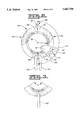
- FIG. 1 is a diagrammatic side view of an item to be laser cut and having the deflector of this invention positioned thereon;
- FIG. 2 is a diagrammatic top view of the deflector
- FIG. 3 is a diagrammatic top view of a deflector of a different design.
- FIG. 4 is a diagrammatic enlarged partial top view of the deflector and the item to be laser cut.
- a laser beam deflector 10 is provided for protecting an underlying portion(s) 12 of an item, such as a timing gear 14, during laser cutting of overlying stock 16.
- the underlying portions of the subject embodiment are gear teeth 18.
- the timing gear 14 has an axial centerline 20.
- timing notches 22 are being cut in the overlaying stock 16 of the timing gear 14 by a laser cutting apparatus a portion of which is illustrated at 24. It should be understood, however that the item 14 can be other than a timing gear 14 without departing from this invention.
- the overlaying stock 16 has an outer peripheral surface 26 and the notches 22 have a depth "D".
- the overlaying stock 16 is separated from the gear teeth 12 by a circumferentially extending groove 28 having a groove depth "GD", as measured from a bottom of the groove 28 to the overlying stock outer peripheral surface 26.
- the groove 28 has a groove radius "GR” and a groove width "GW”.
- the laser beam deflector 10 has a smooth deflecting surface "ds”, a base surface “bs”, a base surface width "bsw”, a thickness "t”, a radius “r”, and an arcuate length "l".
- the deflector 10 has dimensions relative to the gear wherein, the base surface width "bsw” is greater than the groove depth "GD", the deflector radius "r” is substantially equal to the groove radius "GR”, the thickness "t” of the deflector is less than the groove width "GW”, the deflector arcuate length "l” extends at least 120 degrees, and the deflecting surface "ds" is of an arcuate cross-sectional configuration.
- the deflector 10 is positionable between the overlaying stock 16 and the underlying portions 12 desired to be protected and with the deflecting surface "ds" immediately adjacent the overlaying stock 16.
- the deflector 10 is defined by first and second deflector portion 30 and 32 each having first and second end portion 34 and 36 and an arcuate length "l" of about 180 degrees.
- the first and second portion 30 and 32 are pivotally connected one to the other.
- Means 38 releasable connects the second ends 36 of the deflector portions one to the other.
- the second ends 36 of the deflector portions 30 and 32 overlap each other and the means 38 for releasably connecting the second ends 36 includes a pivot pin 40 that extends though the overlapping second ends.
- a handle 42 extends radially outward from each first end portion 30 to aid in the manual pivoting of the first and second portions 30 and 32 about pivot 40.
- FIG. 3 is a diagrammatic top view of a laser beam deflector 10' of a different design.
- the deflector 10' has an arcuate length "l” extending at least 120 degrees and a handle 42' that extend radially outwardly intermediate its ends.
- the deflector 10' has a smooth deflecting surface "ds”, a base surface “bs”, a base surface width "bsw”, a thickness "t", and a radius "r” identical to the deflector 10.
- the deflector is positionable between the overlaying stock and the underlying portions desired to be protected and with the deflecting surface "ds" immediately adjacent the overlaying stock.
- the deflectors 10, 10' are positionable between the overlaying stock 16 and the underlying portions 12 desired to be protected with the deflecting surface "ds" immediately adjacent the overlaying stock 16.
- the laser cutting apparatus emits a beam which is used to cut the timing notches in the overlaying stock 16.
- the beam is harmlessly diffused away from the underlaying gear teeth 18 by the smooth arcuate deflecting surface "ds".
- the laser beam deflector 10, 10' is manufactured from copper or alternatively from other highly reflective material.
- the first and second portion 30 and 32 are hinged together and positionable in the groove 28.
Abstract
A laser beam deflector is useable for protecting underlying portions of an item during laser cutting of overlaying stock. The deflector has a base surface width greater than the overlying stock to be cut and a smooth deflecting surface of an arcuate cross-sectional configuration. The deflector is positionable between the overlaying stock and the underlying portions desired to be protected with the deflecting surface immediately adjacent the overlaying stock.
Description
The present invention relates to a laser beam deflector for protecting underlying apparatus while laser cutting overlaying stock. More particularly, the present invention relates to a laser beam deflector used in the manufacture of a timing gear or the like.
1. Background Art
In the art of manufacturing using lasers to cut metal to form an article, such as for example a gear, underlying portions of the gear or other element may be damaged. Such has been the case in manufacturing timing gears. In order to avoid such damage, these type gears and other equipment has generally been formed by a shaper.
Shaper forming of teeth and notches is slow and requires the waste of manpower, time, money, and natural resources relative to the work that can be accomplished by laser cutting.
The present invention is directed to overcoming one or more of the problems as set forth above.
2. Disclosure of the Invention
In one aspect of the invention, a laser beam deflector is provided for protecting underlying portions of an item during laser cutting of overlaying stock. The deflector has a base surface width greater than the depth of the overlying stock to be cut and a deflector surface "ds" of an arcuate cross-sectional configuration. The deflector is positionable between the overlaying stock and the underlying portions desired to be protected and with the deflection surface "ds" immediately adjacent the overlaying stock.
In another aspect of the invention, a laser beam deflector is provided for protecting underlying gear teeth of a gear during laser cutting of notches in overlaying stock. The overlaying stock has an outer surface. The notches have a depth "D" and are separated from the gear teeth by a circumferentially extending groove. The notches further have a groove depth "D" as measured from a bottom of the groove to the overlying stock outer surface, a groove radius "GR" and a groove width "GW". The deflector has a deflecting surface "ds", a base surface "bs", a base surface width "bsw", a thickness "t", a radius "r" and an arcuate length "l". The deflector has dimensions relative to the gear such that the base surface width "bsw" is greater than the groove depth "GD", the radius "r" is substantially equal to the groove radius "GR", the thickness "t" is less than the groove width "GW", the arcuate length extends at least 120 degrees, and the deflecting surface "ds" is of an arcuate cross-sectional configuration.
FIG. 1 is a diagrammatic side view of an item to be laser cut and having the deflector of this invention positioned thereon;
FIG. 2 is a diagrammatic top view of the deflector;
FIG. 3 is a diagrammatic top view of a deflector of a different design; and
FIG. 4 is a diagrammatic enlarged partial top view of the deflector and the item to be laser cut.
Referring to FIGS. 1, 2, and 4, a laser beam deflector 10 is provided for protecting an underlying portion(s) 12 of an item, such as a timing gear 14, during laser cutting of overlying stock 16. The underlying portions of the subject embodiment are gear teeth 18. The timing gear 14 has an axial centerline 20. In the item of FIG. 1, timing notches 22 are being cut in the overlaying stock 16 of the timing gear 14 by a laser cutting apparatus a portion of which is illustrated at 24. It should be understood, however that the item 14 can be other than a timing gear 14 without departing from this invention.
The overlaying stock 16 has an outer peripheral surface 26 and the notches 22 have a depth "D". Referring to FIG. 4, the overlaying stock 16 is separated from the gear teeth 12 by a circumferentially extending groove 28 having a groove depth "GD", as measured from a bottom of the groove 28 to the overlying stock outer peripheral surface 26. The groove 28 has a groove radius "GR" and a groove width "GW".
As shown in FIGS. 2 and 4, the laser beam deflector 10 has a smooth deflecting surface "ds", a base surface "bs", a base surface width "bsw", a thickness "t", a radius "r", and an arcuate length "l". The deflector 10 has dimensions relative to the gear wherein, the base surface width "bsw" is greater than the groove depth "GD", the deflector radius "r" is substantially equal to the groove radius "GR", the thickness "t" of the deflector is less than the groove width "GW", the deflector arcuate length "l" extends at least 120 degrees, and the deflecting surface "ds" is of an arcuate cross-sectional configuration.
As shown in FIGS. 1 and 2, the deflector 10 is positionable between the overlaying stock 16 and the underlying portions 12 desired to be protected and with the deflecting surface "ds" immediately adjacent the overlaying stock 16. As best shown in FIG. 2, the deflector 10 is defined by first and second deflector portion 30 and 32 each having first and second end portion 34 and 36 and an arcuate length "l" of about 180 degrees. The first and second portion 30 and 32 are pivotally connected one to the other. Means 38 releasable connects the second ends 36 of the deflector portions one to the other. The second ends 36 of the deflector portions 30 and 32 overlap each other and the means 38 for releasably connecting the second ends 36 includes a pivot pin 40 that extends though the overlapping second ends. A handle 42 extends radially outward from each first end portion 30 to aid in the manual pivoting of the first and second portions 30 and 32 about pivot 40.
FIG. 3 is a diagrammatic top view of a laser beam deflector 10' of a different design. The deflector 10' has an arcuate length "l" extending at least 120 degrees and a handle 42' that extend radially outwardly intermediate its ends. The deflector 10' has a smooth deflecting surface "ds", a base surface "bs", a base surface width "bsw", a thickness "t", and a radius "r" identical to the deflector 10. The deflector is positionable between the overlaying stock and the underlying portions desired to be protected and with the deflecting surface "ds" immediately adjacent the overlaying stock.
The deflectors 10, 10' are positionable between the overlaying stock 16 and the underlying portions 12 desired to be protected with the deflecting surface "ds" immediately adjacent the overlaying stock 16. The laser cutting apparatus emits a beam which is used to cut the timing notches in the overlaying stock 16. The beam is harmlessly diffused away from the underlaying gear teeth 18 by the smooth arcuate deflecting surface "ds". Preferably the laser beam deflector 10, 10' is manufactured from copper or alternatively from other highly reflective material. The first and second portion 30 and 32 are hinged together and positionable in the groove 28.
Claims (6)
1. A laser beam deflector for protecting underlying portions of an item during laser cutting of overlaying stock, comprising:
a deflecting surface "ds" of an arcuate cross-sectional configuration, said deflector being defined by first and second portions each having first and second end portions and an arcuate length "l" of about 180 degrees, said first end portions being pivotally connected to one another, said deflector being positionable between said overlaying stock and underlying portions desired to be protected, and said deflecting surface "ds" being immediately adjacent said overlaying stock.
2. A laser beam deflector for protecting underlying gear teeth of a gear during laser cutting of notches in overlaying stock, comprising said overlaying stock having an outer surface and being separated from the gear teeth by a circumferentially extending groove having a groove depth "GD", as measured from a bottom of the groove to the overlying stock outer surface, a groove radius "GR" and a groove width "GW", said notches having a depth "D";
said deflector having a deflecting surface "ds" a base surface "bs" a base surface width "bsw" a thickness "t", a radius "r", and an arcuate length "l"; said deflector having dimensions relative to the gear wherein, said base service width "bsw" is greater than the groove depth "GD" said deflector radius "r" is substantially equal to the groove radius "GR", said thickness "t" of the deflector is less than the groove width "GW", said deflector arcuate length "l" extends at least 120 degrees, and said deflecting surface "ds" is of arcuate cross-sectional configuration.
3. A deflector, as set forth in claim 2, wherein the arcuate length "l" is about 360 degrees.
4. A deflector, as set forth in claim 3, wherein the deflector is defined by first and second portions each having first and second end portions and an arcuate length "l" of about 180 degrees, said first end portions being pivotally connected one to the other.
5. A deflector, as set forth in claim 4, including means for releasable connecting the second ends of the deflector portions one to the other.
6. A deflector, as set forth in claim 2, wherein the deflecting surface "ds" is of convex cross-sectional configuration.
Priority Applications (1)
| Application Number | Priority Date | Filing Date | Title |
|---|---|---|---|
| US08/614,232 US5667708A (en) | 1996-03-12 | 1996-03-12 | Laser beam deflector for protection of underlying portions of an item during laser cutting of overlaying stock |
Applications Claiming Priority (1)
| Application Number | Priority Date | Filing Date | Title |
|---|---|---|---|
| US08/614,232 US5667708A (en) | 1996-03-12 | 1996-03-12 | Laser beam deflector for protection of underlying portions of an item during laser cutting of overlaying stock |
Publications (1)
| Publication Number | Publication Date |
|---|---|
| US5667708A true US5667708A (en) | 1997-09-16 |
Family
ID=24460382
Family Applications (1)
| Application Number | Title | Priority Date | Filing Date |
|---|---|---|---|
| US08/614,232 Expired - Fee Related US5667708A (en) | 1996-03-12 | 1996-03-12 | Laser beam deflector for protection of underlying portions of an item during laser cutting of overlaying stock |
Country Status (1)
| Country | Link |
|---|---|
| US (1) | US5667708A (en) |
Cited By (14)
| Publication number | Priority date | Publication date | Assignee | Title |
|---|---|---|---|---|
| US6233736B1 (en) | 1996-02-08 | 2001-05-15 | Media Online Services, Inc. | Media online service access system and method |
| US20020007406A1 (en) * | 1995-11-13 | 2002-01-17 | Lakshmi Arunachalam | Value-added network switching and object routing |
| US6355322B1 (en) | 1998-12-08 | 2002-03-12 | 3M Innovative Properties Company | Release liner incorporating a metal layer |
| US20020178060A1 (en) * | 2001-05-25 | 2002-11-28 | Sheehan Patrick M. | System and method for providing and redeeming electronic paperless coupons |
| US20030212996A1 (en) * | 1996-02-08 | 2003-11-13 | Wolzien Thomas R. | System for interconnection of audio program data transmitted by radio to remote vehicle or individual with GPS location |
| US7120871B1 (en) | 1999-09-15 | 2006-10-10 | Actv, Inc. | Enhanced video programming system and method utilizing a web page staging area |
| US7243139B2 (en) | 1996-03-08 | 2007-07-10 | Open Tv Corporation | Enhanced video programming system and method for incorporating and displaying retrieved integrated Internet information segments |
| US20070184705A1 (en) * | 2006-02-09 | 2007-08-09 | Snecma | Laser cutting method |
| EP1950000A1 (en) * | 2007-01-26 | 2008-07-30 | Rolls-Royce plc | Apparatus with a beam generator and a beam trap ; Method for machining a component using a beam and a beam trap |
| US20090188903A1 (en) * | 2008-01-24 | 2009-07-30 | Gm Global Technology Operations, Inc. | Method for welding process consistency |
| US7757265B2 (en) | 2000-03-31 | 2010-07-13 | Intellocity Usa Inc. | System and method for local meta data insertion |
| US7930716B2 (en) | 2002-12-31 | 2011-04-19 | Actv Inc. | Techniques for reinsertion of local market advertising in digital video from a bypass source |
| US7949722B1 (en) | 1999-09-29 | 2011-05-24 | Actv Inc. | Enhanced video programming system and method utilizing user-profile information |
| US8037158B2 (en) | 1995-11-13 | 2011-10-11 | Lakshmi Arunachalam | Multimedia transactional services |
Citations (10)
| Publication number | Priority date | Publication date | Assignee | Title |
|---|---|---|---|---|
| DE254543C (en) * | ||||
| US3865114A (en) * | 1972-10-11 | 1975-02-11 | Laser Ind Ltd | Laser device particularly useful as a surgical instrument |
| JPS5966032A (en) * | 1982-10-06 | 1984-04-14 | Toshiba Corp | Glass working method |
| US4465919A (en) * | 1980-03-24 | 1984-08-14 | Roeder Walter | Cutting apparatus for three-dimensional mouldings |
| JPS6182986A (en) * | 1984-09-28 | 1986-04-26 | Mitsubishi Electric Corp | Laser cutting method |
| JPS61269996A (en) * | 1985-05-27 | 1986-11-29 | Toyota Motor Corp | Radiation beam piercing method |
| US4891028A (en) * | 1989-04-11 | 1990-01-02 | Zenith Electronics Corporation | Shielding means and process for use in the manufacture of tension mask color cathode ray tubes |
| JPH04333389A (en) * | 1991-05-09 | 1992-11-20 | Nec Corp | Laser beam machining device |
| JPH0655291A (en) * | 1992-08-07 | 1994-03-01 | Toshiba Corp | Laser beam processing method |
| US5516998A (en) * | 1992-12-30 | 1996-05-14 | Societe Nationale D'etude Et De Construction De Moteurs D'aviation "Snecma" | Laser beam machining process and apparatus |
-
1996
- 1996-03-12 US US08/614,232 patent/US5667708A/en not_active Expired - Fee Related
Patent Citations (10)
| Publication number | Priority date | Publication date | Assignee | Title |
|---|---|---|---|---|
| DE254543C (en) * | ||||
| US3865114A (en) * | 1972-10-11 | 1975-02-11 | Laser Ind Ltd | Laser device particularly useful as a surgical instrument |
| US4465919A (en) * | 1980-03-24 | 1984-08-14 | Roeder Walter | Cutting apparatus for three-dimensional mouldings |
| JPS5966032A (en) * | 1982-10-06 | 1984-04-14 | Toshiba Corp | Glass working method |
| JPS6182986A (en) * | 1984-09-28 | 1986-04-26 | Mitsubishi Electric Corp | Laser cutting method |
| JPS61269996A (en) * | 1985-05-27 | 1986-11-29 | Toyota Motor Corp | Radiation beam piercing method |
| US4891028A (en) * | 1989-04-11 | 1990-01-02 | Zenith Electronics Corporation | Shielding means and process for use in the manufacture of tension mask color cathode ray tubes |
| JPH04333389A (en) * | 1991-05-09 | 1992-11-20 | Nec Corp | Laser beam machining device |
| JPH0655291A (en) * | 1992-08-07 | 1994-03-01 | Toshiba Corp | Laser beam processing method |
| US5516998A (en) * | 1992-12-30 | 1996-05-14 | Societe Nationale D'etude Et De Construction De Moteurs D'aviation "Snecma" | Laser beam machining process and apparatus |
Cited By (23)
| Publication number | Priority date | Publication date | Assignee | Title |
|---|---|---|---|---|
| US20020007406A1 (en) * | 1995-11-13 | 2002-01-17 | Lakshmi Arunachalam | Value-added network switching and object routing |
| US8037158B2 (en) | 1995-11-13 | 2011-10-11 | Lakshmi Arunachalam | Multimedia transactional services |
| US6233736B1 (en) | 1996-02-08 | 2001-05-15 | Media Online Services, Inc. | Media online service access system and method |
| US20030212996A1 (en) * | 1996-02-08 | 2003-11-13 | Wolzien Thomas R. | System for interconnection of audio program data transmitted by radio to remote vehicle or individual with GPS location |
| US7243139B2 (en) | 1996-03-08 | 2007-07-10 | Open Tv Corporation | Enhanced video programming system and method for incorporating and displaying retrieved integrated Internet information segments |
| US7409437B2 (en) | 1996-03-08 | 2008-08-05 | Actv, Inc. | Enhanced video programming system and method for incorporating and displaying retrieved integrated Internet information segments |
| US6355322B1 (en) | 1998-12-08 | 2002-03-12 | 3M Innovative Properties Company | Release liner incorporating a metal layer |
| US7120871B1 (en) | 1999-09-15 | 2006-10-10 | Actv, Inc. | Enhanced video programming system and method utilizing a web page staging area |
| US10205998B2 (en) | 1999-09-29 | 2019-02-12 | Opentv, Inc. | Enhanced video programming system and method utilizing user-profile information |
| US9148684B2 (en) | 1999-09-29 | 2015-09-29 | Opentv, Inc. | Enhanced video programming system and method utilizing user-profile information |
| US8621541B2 (en) | 1999-09-29 | 2013-12-31 | Opentv, Inc. | Enhanced video programming system and method utilizing user-profile information |
| US7949722B1 (en) | 1999-09-29 | 2011-05-24 | Actv Inc. | Enhanced video programming system and method utilizing user-profile information |
| US7757265B2 (en) | 2000-03-31 | 2010-07-13 | Intellocity Usa Inc. | System and method for local meta data insertion |
| US20020178060A1 (en) * | 2001-05-25 | 2002-11-28 | Sheehan Patrick M. | System and method for providing and redeeming electronic paperless coupons |
| US7930716B2 (en) | 2002-12-31 | 2011-04-19 | Actv Inc. | Techniques for reinsertion of local market advertising in digital video from a bypass source |
| US7696451B2 (en) | 2006-02-09 | 2010-04-13 | Snecma | Laser cutting method |
| CN101015882B (en) * | 2006-02-09 | 2010-05-19 | 斯奈克玛 | Laser cutting method |
| EP1818130A1 (en) * | 2006-02-09 | 2007-08-15 | Snecma | Process of laser cutting an opening in a metallic plate using a protection plate having also an opening |
| FR2897006A1 (en) * | 2006-02-09 | 2007-08-10 | Snecma Sa | LASER BEAM CUTTING PROCESS |
| US20070184705A1 (en) * | 2006-02-09 | 2007-08-09 | Snecma | Laser cutting method |
| EP1950000A1 (en) * | 2007-01-26 | 2008-07-30 | Rolls-Royce plc | Apparatus with a beam generator and a beam trap ; Method for machining a component using a beam and a beam trap |
| US8071911B2 (en) | 2007-01-26 | 2011-12-06 | Rolls-Royce Plc | Method and apparatus for machining using a beam and a beam trap |
| US20090188903A1 (en) * | 2008-01-24 | 2009-07-30 | Gm Global Technology Operations, Inc. | Method for welding process consistency |
Similar Documents
| Publication | Publication Date | Title |
|---|---|---|
| US5667708A (en) | Laser beam deflector for protection of underlying portions of an item during laser cutting of overlaying stock | |
| EP0775547B1 (en) | Drill Insert | |
| PL331467A1 (en) | Cutting tool tip | |
| CA1110289A (en) | Sealing ring with diameter indicia | |
| US5841100A (en) | Method of making anti-slip handles | |
| AU604926B2 (en) | Blade construction for use in slicing material webs | |
| WO1999039884A8 (en) | Cutting apparatus and cutting method | |
| US7264428B2 (en) | Hole saw and cutter | |
| EP0931616A3 (en) | Saw wire with cutting elements having a differentiated outer contour | |
| EP1175971B1 (en) | Hairdressing scissors for cutting a small amount of hair in a particular style | |
| AU596399B2 (en) | Cable connection sleeve | |
| JPH02107806A (en) | Thrust sliding bearing composed of layer material and manufacture thereof | |
| CN1409659A (en) | Interconnection between two-surface or multi-surface thin strip-shaped layers that lie on top of the other, in particular, between two strips undergoning continuous processing | |
| EP1224411B1 (en) | A chain joint assembly and a method for the manufacture thereof | |
| CA2206947A1 (en) | Perforation rule for rotary cutting system | |
| WO2001042152A3 (en) | Method and device for cutting flat work pieces made of a brittle material | |
| WO2000032341B1 (en) | Cutting tool and cutting edge configuration thereof | |
| EP0601630A1 (en) | Metal rod and a method for manufacturing same | |
| US3959862A (en) | Rotary cutting tool | |
| JPH11508777A (en) | Fine tooth profile for cutting tools, especially knives | |
| US6389945B1 (en) | Saw blade for forming curved stock | |
| EP1356748B1 (en) | Brush and method for manufacturing such a brush | |
| CA1078811A (en) | Crown block and method of making sheaves | |
| US6454204B1 (en) | Rotatable supporting element | |
| EP1682318B1 (en) | Disc saw blade |
Legal Events
| Date | Code | Title | Description |
|---|---|---|---|
| AS | Assignment |
Owner name: CATERPILLAR INC., ILLINOIS Free format text: ASSIGNMENT OF ASSIGNORS INTEREST;ASSIGNORS:GLASS, ROBERT H.;KELLY, GORDON W.;REEL/FRAME:007901/0066;SIGNING DATES FROM 19960229 TO 19960306 |
|
| REMI | Maintenance fee reminder mailed | ||
| LAPS | Lapse for failure to pay maintenance fees | ||
| FP | Lapsed due to failure to pay maintenance fee |
Effective date: 20010916 |
|
| STCH | Information on status: patent discontinuation |
Free format text: PATENT EXPIRED DUE TO NONPAYMENT OF MAINTENANCE FEES UNDER 37 CFR 1.362 |