US5653321A - Clutching device - Google Patents
Clutching device Download PDFInfo
- Publication number
- US5653321A US5653321A US08/507,150 US50715095A US5653321A US 5653321 A US5653321 A US 5653321A US 50715095 A US50715095 A US 50715095A US 5653321 A US5653321 A US 5653321A
- Authority
- US
- United States
- Prior art keywords
- friction plates
- flexible member
- spline
- plates
- rotatable
- Prior art date
- Legal status (The legal status is an assumption and is not a legal conclusion. Google has not performed a legal analysis and makes no representation as to the accuracy of the status listed.)
- Expired - Lifetime
Links
Images


Classifications
-
- F—MECHANICAL ENGINEERING; LIGHTING; HEATING; WEAPONS; BLASTING
- F16—ENGINEERING ELEMENTS AND UNITS; GENERAL MEASURES FOR PRODUCING AND MAINTAINING EFFECTIVE FUNCTIONING OF MACHINES OR INSTALLATIONS; THERMAL INSULATION IN GENERAL
- F16D—COUPLINGS FOR TRANSMITTING ROTATION; CLUTCHES; BRAKES
- F16D65/00—Parts or details
- F16D65/02—Braking members; Mounting thereof
- F16D65/12—Discs; Drums for disc brakes
- F16D65/123—Discs; Drums for disc brakes comprising an annular disc secured to a hub member; Discs characterised by means for mounting
-
- F—MECHANICAL ENGINEERING; LIGHTING; HEATING; WEAPONS; BLASTING
- F16—ENGINEERING ELEMENTS AND UNITS; GENERAL MEASURES FOR PRODUCING AND MAINTAINING EFFECTIVE FUNCTIONING OF MACHINES OR INSTALLATIONS; THERMAL INSULATION IN GENERAL
- F16D—COUPLINGS FOR TRANSMITTING ROTATION; CLUTCHES; BRAKES
- F16D13/00—Friction clutches
- F16D13/58—Details
- F16D13/60—Clutching elements
- F16D13/64—Clutch-plates; Clutch-lamellae
- F16D13/648—Clutch-plates; Clutch-lamellae for clutches with multiple lamellae
-
- F—MECHANICAL ENGINEERING; LIGHTING; HEATING; WEAPONS; BLASTING
- F16—ENGINEERING ELEMENTS AND UNITS; GENERAL MEASURES FOR PRODUCING AND MAINTAINING EFFECTIVE FUNCTIONING OF MACHINES OR INSTALLATIONS; THERMAL INSULATION IN GENERAL
- F16D—COUPLINGS FOR TRANSMITTING ROTATION; CLUTCHES; BRAKES
- F16D25/00—Fluid-actuated clutches
- F16D25/06—Fluid-actuated clutches in which the fluid actuates a piston incorporated in, i.e. rotating with the clutch
- F16D25/062—Fluid-actuated clutches in which the fluid actuates a piston incorporated in, i.e. rotating with the clutch the clutch having friction surfaces
- F16D25/063—Fluid-actuated clutches in which the fluid actuates a piston incorporated in, i.e. rotating with the clutch the clutch having friction surfaces with clutch members exclusively moving axially
- F16D25/0635—Fluid-actuated clutches in which the fluid actuates a piston incorporated in, i.e. rotating with the clutch the clutch having friction surfaces with clutch members exclusively moving axially with flat friction surfaces, e.g. discs
- F16D25/0638—Fluid-actuated clutches in which the fluid actuates a piston incorporated in, i.e. rotating with the clutch the clutch having friction surfaces with clutch members exclusively moving axially with flat friction surfaces, e.g. discs with more than two discs, e.g. multiple lamellae
-
- F—MECHANICAL ENGINEERING; LIGHTING; HEATING; WEAPONS; BLASTING
- F16—ENGINEERING ELEMENTS AND UNITS; GENERAL MEASURES FOR PRODUCING AND MAINTAINING EFFECTIVE FUNCTIONING OF MACHINES OR INSTALLATIONS; THERMAL INSULATION IN GENERAL
- F16D—COUPLINGS FOR TRANSMITTING ROTATION; CLUTCHES; BRAKES
- F16D55/00—Brakes with substantially-radial braking surfaces pressed together in axial direction, e.g. disc brakes
- F16D55/24—Brakes with substantially-radial braking surfaces pressed together in axial direction, e.g. disc brakes with a plurality of axially-movable discs, lamellae, or pads, pressed from one side towards an axially-located member
- F16D55/26—Brakes with substantially-radial braking surfaces pressed together in axial direction, e.g. disc brakes with a plurality of axially-movable discs, lamellae, or pads, pressed from one side towards an axially-located member without self-tightening action
- F16D55/36—Brakes with a plurality of rotating discs all lying side by side
-
- F—MECHANICAL ENGINEERING; LIGHTING; HEATING; WEAPONS; BLASTING
- F16—ENGINEERING ELEMENTS AND UNITS; GENERAL MEASURES FOR PRODUCING AND MAINTAINING EFFECTIVE FUNCTIONING OF MACHINES OR INSTALLATIONS; THERMAL INSULATION IN GENERAL
- F16D—COUPLINGS FOR TRANSMITTING ROTATION; CLUTCHES; BRAKES
- F16D65/00—Parts or details
- F16D65/0006—Noise or vibration control
-
- F—MECHANICAL ENGINEERING; LIGHTING; HEATING; WEAPONS; BLASTING
- F16—ENGINEERING ELEMENTS AND UNITS; GENERAL MEASURES FOR PRODUCING AND MAINTAINING EFFECTIVE FUNCTIONING OF MACHINES OR INSTALLATIONS; THERMAL INSULATION IN GENERAL
- F16H—GEARING
- F16H63/00—Control outputs from the control unit to change-speed- or reversing-gearings for conveying rotary motion or to other devices than the final output mechanism
- F16H63/02—Final output mechanisms therefor; Actuating means for the final output mechanisms
- F16H63/30—Constructional features of the final output mechanisms
- F16H63/3023—Constructional features of the final output mechanisms the final output mechanisms comprising elements moved by fluid pressure
- F16H63/3026—Constructional features of the final output mechanisms the final output mechanisms comprising elements moved by fluid pressure comprising friction clutches or brakes
-
- F—MECHANICAL ENGINEERING; LIGHTING; HEATING; WEAPONS; BLASTING
- F16—ENGINEERING ELEMENTS AND UNITS; GENERAL MEASURES FOR PRODUCING AND MAINTAINING EFFECTIVE FUNCTIONING OF MACHINES OR INSTALLATIONS; THERMAL INSULATION IN GENERAL
- F16D—COUPLINGS FOR TRANSMITTING ROTATION; CLUTCHES; BRAKES
- F16D65/00—Parts or details
- F16D65/02—Braking members; Mounting thereof
- F16D2065/13—Parts or details of discs or drums
- F16D2065/134—Connection
- F16D2065/1348—Connection resilient
-
- F—MECHANICAL ENGINEERING; LIGHTING; HEATING; WEAPONS; BLASTING
- F16—ENGINEERING ELEMENTS AND UNITS; GENERAL MEASURES FOR PRODUCING AND MAINTAINING EFFECTIVE FUNCTIONING OF MACHINES OR INSTALLATIONS; THERMAL INSULATION IN GENERAL
- F16D—COUPLINGS FOR TRANSMITTING ROTATION; CLUTCHES; BRAKES
- F16D65/00—Parts or details
- F16D65/02—Braking members; Mounting thereof
- F16D2065/13—Parts or details of discs or drums
- F16D2065/134—Connection
- F16D2065/1356—Connection interlocking
- F16D2065/1368—Connection interlocking with relative movement both radially and axially
Definitions
- the present invention relates to a clutching device that is installed in an automatic transmission, such as a multiple-plate clutch or a multiple-plate brake.
- the speed change mechanism includes a plurality of planetary gears, clutchs, and brakes, and acquires a speed change output at a required speed change ratio from the set of planetary gears by varying the engaging combinations for the clutchs and the brakes.
- the general clutch and brake have a multiple plate structure, arranged wherein are "two support members that rotate relatively to each other while their splines are opposite each other in the direction of the diameter" and "a hydraulic piston mechanism.”
- friction plates that engage one of the two splines and friction plates that engage the other spline are alternately positioned so as to share a ring-shaped overlapped area, and the piston mechanism, shifting in a direction of a relative rotational axis, imposes pressure on the overlapping plates, and permits that pressure to act on the overlapping portion of the friction plates.”
- a leaf spring that uniformly forces upward friction plates which are on the case side of the multiple-plate brake, is provided at the lowest position of the case-side friction plates to prevent the friction plates from falling due to gravity.
- a spring member has a large comb shape and is formed by a complicated bending process.
- Other structures that prevent the wobbling and vibration of a friction plate are disclosed in Japanese Utility Model Application Laid-open Nos. 56-101223 and 2-36631.
- the friction plates are forced to an eccentric position, and intervals between the edge faces of the friction plates and the spline faces vary.
- an excessive pressure acts on a limited few edge faces and as a result these edge faces are deformed.
- the wobbling of the friction plates is increased, and the movement of the friction plates is more eccentric.
- the eccentricity of the friction plates reduces the service life of the friction plates in the sense that during braking the pressure state varies depending on each of the spline faces around the circumference, and results in uneconomic design because it must require unreasonably high safety rate.
- a clutching device comprises:
- the edge faces of the friction plates are forced in one circumferential direction by the flexible member, i.e.,in a direction in which the edge face to which a load is applied during the engagement of a clutch or a brake, is pressed against the opposite spline face.
- the positional relationship, in the circumferential direction, of the edge face, to which a load is applied during engagement, and the spline face, which is opposite to the edge face, is identical in the engaged state and in the disengaged state, and the space in which vibration occurs during the disengagement is eliminated. Thus, wobbling and vibration does not occur.
- the movement of the friction plates does not become eccentric when the friction plates are forced in a circumferential direction, unlike when they are forced in the direction of the diameter (upward and downward). Even in the disengaged state, a load is applied to the entire edge face of the friction plates to maintain almost the same contact condition with the spline faces as exists in the engaged state. Then, when engagement is performed suddenly, impacting of the edge faces against the spline faces does not occur. Therefore, the pressure conditions at the edge faces are uniform, deformation is not caused by variable pressure conditions, and the vibration f the friction plates is not extended, even when engagement and disengagement are repeated frequently.
- a clutching device When a clutching device is a multiple plate clutch, the rotational positions of the friction plates different in consonance with the phase positions where the engagement is released and halted.
- a clutching device When a clutching device is a multiple plate brake, one of the friction plates has constant fixed rotation relative to the case. In the multiple plate brake, the positions of the flexible members that are inserted between the friction plates and the spline faces are constant.
- a clutching device which comprises: a plurality of first friction plates, which engage splines provided in a case of an automatic transmission; a plurality of second friction plates, which are alternately positioned with the first friction plates and that engage a spline that is formed in a member that is rotatable relative to the case; a hydraulic piston mechanism, for shifting in a direction of a rotational axis, for pressing together the first and the second friction plates, and for exerting pressure on a ring-shaped area where the first and the second friction plates overlap; and a flexible member, for forcing the first friction plates almost in a circumferential direction, that is inserted between edge faces of the first friction plates, which are positioned at an angle such that a rotational direction of the rotatable member is diagonally upward toward the center and which are on a side at which no load is applied during engagement, and a spline face, which is opposite to the edge faces.
- the flexible members are provided at a position where the greatest effect for the prevention of wobbling can be acquired in consonance with the characteristic of the vibration of the first friction plates that actually occurs.
- the vibration of the first friction plates caused reciprocating rotational movements of the upper half of the rotatable member at the point where the rotation ascends, while employing as a fulcrum one meshing portion of the lower half of the rotatable member where the rotation descends.
- the flexible member is located in one meshing portion in an area, the farthest from the fulcrum, where a vibration direction and a direction in which the flexible member is bent are identical, i.e., an area where the upper half of the rotatable member ascends during its rotation, that is, where rotation of the second friction plates is diagonally upward toward the center.
- the flexible member could be formed by bending a thin metal plate into a bellows shape and inserted in the direction of the rotation axis of the rotatable member, so that the flexible member uniformly forces the first friction plates while faces of an M-shaped cross section of the flexible member abut upon the edge faces and the spline face, respectively.
- the spring member (flexible member), which has a bellow-shaped cross section and which bends in alternate direction, forces a plurality of the first friction plates in a circumferential direction at the same time as it presses the load-applied edge faces against the opposite spline faces.
- the spring member need only to be linear and as wide as or narrower than the height of the spline.
- the spring member can be attached simply by inserting it into a gap between the edge face and the spline and parallel to the spline. Since the clearance in a circumferential direction between the edge face and the spline is smaller than the vibration width in the direction of the diameter, the maximum allowable deformation value for the spring member can be very small.
- It is still another object of the present invention to provide a clutching device which comprises: a plurality of first friction plates, which engage a spline provided in a case of an automatic transmission; a plurality of second friction plates, which are alternately positioned with the first friction plates and which engage a spline that is formed in a member that is rotatable relative to the case; a hydraulic piston mechanism, for shifting in a direction of a rotational axis, for pressing together the first and the second friction plates, and for exerting pressure on a ring-shaped area where the first and the second friction plates overlap; and a weight board, which is attached at a position other than where the first friction plates overlap the second friction plates to increase the weight of the first friction plates.
- the inertial weight of the first friction plate is increased so that it will not be easily pulled by a second friction plate that is rotating.
- the weight board is attached only within a range having a constant angle to increase the moment of inertia per weight.
- a weight board that is equal in thickness to or thinner than the second friction plate does not interfere with the clutch locking even if it is located at an external position in the direction of the diameter of the second friction plate.
- a clutching device which comprises: aplurality of first friction plates, which engage a spline that is provided in a case of an automatic transmission; a plurality of second friction plates that are alternately positioned with the first friction plates and which engage a spline that is formed in a member that is rotatable relative to the case; a hydraulic piston mechanism for shifting in a direction of a rotational axis, for pressing together the first and the second friction plates, and for exerting pressure on a ring-shaped area where the first and the second friction plates overlap; a pin hole that is formed at a position at such an angle that a rotational direction of the rotatable member is diagonally upward to the center and that is not within the area where the first friction plates overlap the second friction plates; and a pin shaft, which passes the first friction plates through the pin hole to inhibit relative movement of the first friction plates.
- the pin shaft is employed to mutually couple all the first friction plates, so that relative vibration is prevented at least in the direction that corresponds to the width of the vibration.
- a single first friction plate on which stimulus has acted is only allowed to vibrate while interlocking with all the other first friction plates.
- the inertial mass of a single first friction plate is substantially increased by the pin shaft.
- the pin shaft may be engaged with or held by a member (the bottom wall of the spline, or a retaining plate) that is positioned outside of the friction plate. As the mass obtained by coupling circumferential movement via the pin shaft is large, hardly any vibration occurs.
- FIG. 1 is a partial cross sectional view of an automatic transmission showing a first embodiment of the present invention
- FIGS. 2A though 5B are explanatory diagrams for example flexible members; wherein FIG. 2B is a view along the line B--B of FIG. 2A; FIG. 3B is a cross sectional view taken along the line C--C of FIG. 3A; FIG. 4B is a cross sectional view taken along the line D--D of FIG. 4A; and FIG. 5B is a view along the line E--E of FIG. 5A;
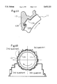
- FIG. 6A is a diagram of a cross section vertical to a shaft of the automatic transmission
- FIG. 6B is an enlarged fragmentary view of the dotted area of FIG. 6A;
- FIG. 7 is a specific diagram illustrating the vibration mode
- FIG. 8 is a diagram showing a vibration preventing mechanism according to a second embodiment of the present invention.
- FIG. 9 is an explanatory diagram showing a vibration preventing mechanism according to a third embodiment of the present invention.
- FIG. 1 one of a plurality of brakes that constitute an automatic transmission is illustrated. Stopping side friction plates that are located outside are driven plates 11, while rotating side friction plates that are located inside are drive plates 12. The rotation of a rotary body 16 that engages the drive plates 12 is prevented by the friction between the driven plates 11 and the drive plates 12.
- a spline 13A is formed on the internal face of a gear box 13 of the automatic transmission, and engages a spline edge that is formed along the outer surfaces of the driven plates 11.
- the internal rotary body 16 is so supported by a bearing 19 and a further internally located member 13D that it can freely rotate.
- the member 13D is fixed to the gear box 13 by a bolt 13B.
- the driven plates 11 can be shifted along the spline 13A in the axial direction of the automatic transmission, while the drive plates 12 can be shifted along the spline 16A in the axial direction of the transmission.
- the drive plates 12 and the driven plates 11, which are alternately overlapped, are sandwiched from the sides between a retaining plate 15 and a hydraulic piston 17.
- the hydraulic piston 17 is driven to the left in the diagram when pressure oil is supplied to a hydraulic chamber 17A, which is formed in a gap between the hydraulic piston 17 and the gear box 13 that is located on the right side.
- a spring 18 abuts upon the hydraulic piston 17 and is supported by a spring seat 18A that is fitted into the member 13D and forces the hydraulic piston 17 toward the right in the diagram.
- the retaining plate 15 has a spline edge formed along its external surface to engage the spline 13A.
- a snap ring 14 that is fixed to the spline 13A restricts its shifting to the left in the diagram.
- the hydraulic piston 17 compresses the spring 18 and moves to the left.
- a flexible member 20 is inserted into one portion around the circumference of the gear box 13, i.e., between the spline 13A and the driven plates 11. Such an angle position is selected that the rotational direction on the drive side is diagonally upward toward the center, and a flexible member is located between the spline face and the edge face to which no load is applied when the friction plate on the brake side is engaged.
- the flexible member 20 is so positioned in the axial direction that its movement is restricted by the rearmost wall of the spline 13A and the snap ring 14.
- the flexible member 20 equally forces the spline edges of all the driven plates 11 in the circumferential direction.
- the flexible member 20 is inserted into the side to which no load is applied when the brake engages. Even when the released condition (disengaged) the spline edges and the spline face, which contact each other at the engagement of the brake, are kept in contact by the flexible member 20. Neither a load that occurs when the brake engages, nor a load that is placed on the driven plates 11, which are pulled by the rotating drive plates during the released condition, acts on the flexible member 20. Therefore, the amount of distortion that will be generated is very small.
- the flexible member 20 Since the load that is applied to the flexible member 20 is always small and an allowable distortion value is also small, it is not necessary for the flexible member 20 to be formed in a complicated comb shape, as in a conventional device where a backing face is provided that corresponds to each of the driven plates 11. Therefor the flexible member 20 has a simple rectangular or a bar shape as shown in FIG. 2A through FIG. 5B. Further, since the condition where a constant light load is applied is always maintained and the shifting of positions does not occur, a specific structure for fixing the flexible member 20 to the spline 13A is not required.
- FIGS. 2A through 5B are explanatory diagrams for some example flexible members.
- a flexible member 20A shown in FIGS. 2A and 2B is made by bending a thin spring steel plate so that it has an arc shape. By bending the spring steel plate only a little at the right side in the diagram, insertion to the right and extraction to the left is facilitated.
- a flexible member 20B shown in FIGS. 3A and 3B is made by bending a thin spring steel plate so that its cross section has a W shape.
- a flexible member 20C shown in FIGS. 4A and 4B is formed in the same manner and has a C shaped cross section.
- a flexible member 20D shown in FIGS. 5A and 5B is made by bonding a resin rubber layer D1 to a thin metal plate D2.
- FIG. 6A the rotation direction of the drive plates 12 shown in FIG. 1 is indicated by the arrow.
- the spline edges of the driven plates 11 are held by the spline 13A that is formed in the gear box 13.
- the flexible member 20B shown in FIG. 3A and 3B is employed.
- the flexible member 20B is mounted in the gap at trailing side of the rotational direction of the drive plate 12.
- the internal drive plate 12 pulls the driven plate 11 in the direction indicated by the arrow. At this time, the gap in which the flexible member 20B is not located is also reduced. The load that is placed on the flexible member 20B is very small, smaller than the weight of the driven plate 11. There is no fluctuation, either.
- FIG. 6B the rotational direction of the drive plate 12 is indicated by the arrow.
- the portion enclosed by the dotted line is the one that is shown in FIG. 6A.
- the flexible member 20B is located at one position around the circumference of the gear box 13, i.e., in one of the gaps in the circumferential direction between the spline 13A and the driven plate 11 in the second quadrant.
- the second quadrant is an area where the rotation of the drive plate 12 ascends toward the center. For restricting the vibration of the driven plate 11, the greatest effect can be obtained when the flexible member is located in the second quadrant rather than in the other quadrants. The reason will be explained while referring to FIG. 7.
- the driven plate 11 is specifically illustrated in FIG. 7.
- the driven plate 11 vibrates as indicated by arrows A1 and A2 by employing, as a fulcrum, one engagement portion of the spline 13A and the driven plate 11 in the fourth quadrant shown in FIG. 6B. Therefore, in the second quadrant, the direction of the amplitude of the vibration corresponds to the circumferential direction of the driven plate 11 in which the flexible member 20 functions fully as a spring.
- the flexible member 20 when located in the second quadrant, efficiently absorbs the amplitude of the vibration.
- the flexible member 20 that forces the driven plates 11 in the circumferential direction is employed so that the driven plates are pressed against the spline 13A in the same manner when the brake is disengaged as they are when the brake engaged.
- the flexible member 20 is located on the side to which no load is applied and forces the driven plates in the circumferential direction, the load that is applied to the flexible member 20 and an allowable distortion value are small.
- the flexible member 20 can be simply structured without requiring a special structure for installation.
- the direction in which the flexible member 20 is distorted corresponds to the direction in which a load due to vibration is applied.
- the maximum effect for restricting vibration can therefore be obtained and the shifting in the position of the flexible member 20, which is caused by the force in the diameter direction, does not occur.
- all the driven plates 11 are pressed uniformly against the spline 13A by a single flexible member 20.
- flexible members may be provided for the individual driven plates 11 or for every 2 or 3 sets of driven plates 11. The material for the flexible member 20B shown in FIG.
- the flexible member 20B may be a thin stainless steel as well as the spring steel plate described above, and the cross section, besides being M-shaped, of the flexible member 20B have another bellows shape, such as a V-shaped bellows, an N-shaped bellows, or a W-shaped bellows.
- the flexible member 20A shown in FIGS. 2A and 2B it is desirable that the flexible member 20A is set in such a way that its arcuate portion abut upon the edge faces of the driven plates and its ends abut upon the face of said spline 13A.
- a weight board is attached to friction plates that are on the stopping side in order to increase the inertial moment.
- a weight board 32 is attached to the lower portion of driven plates 31, which are located in the same manner as are the driven plates 11 for the automatic transmission in FIG. 1 and which function the same as the driven plates 11.
- the weight board 32 is located so that it occupies part of the lower portion of the driven plates 31. Since the area where drive plates (not shown) face the driven plates 31 is the same either with or without the weight board 32 being attached, a pulling force that is due to the drive plates, and which serves as a stimulus force for vibration, is not changed.
- the driven plates 31 can hardly be raised, even when they are pulled, and vibration seldom occurs.
- the weight board 32 is located so that it occupies part of the lower portion of the driven plates 31, the inertial moment around point P1 in FIG. 7 is increased and the rotation in the directions indicated by A1 and A2 occurs hardly at all. In this manner, the vibration of the driven plates can be effectively prevented in this embodiment as in the first embodiment.
- a vibration preventing structure in a third embodiment will be explained while referring to FIG. 9.
- a plurality of friction plates on the stopping side are coupled together by a pin.
- a through hole 41F is formed in a portion 41E where a spline (not shown) engages driven plates 41 that are located in the same manner as are the driven plates 11 in FIG. 1 and that function in the same way.
- the driven plates 41 are coupled to each other by passing a pin 46 through the through hole 41F.
- One end of the pin 46 is securely fitted into a blind hole 43F that is formed in a gear box wall 43, which is located at the rearmost position of the spline (not shown).
- the other end of the pin 46 is fitted into a through hole 45F that is formed in a portion 45E of a retaining plate 45, which is located in the same manner as is the retaining plate 15 in FIG. 1 and which functions in the same way.
- the driven plates 41 can be hung while their centers exactly correspond to the center axis of the automatic transmission. And thus, wobbling in the diameter direction, and the eccentric movement of the driven plates due to the wobbling, can be eliminated.
- the vibration of the driven plates can be effectively restricted by employing the least required number of items and by adding a minimum of processes.
- the clutching device of the present invention compared with the conventional vibration preventing structure, a greater effect for vibration prevention can be obtained by providing smaller components.
- the wobbling of friction plates in the direction of the circumference and in the direction of the diameter can be effectively absorbed. Since the structure is uncomplicated and a small spring member (flexible member) can be used, the costs for the spring members are low. And an assembly structure that holds the spring members that should be located on the spline side is simple, and such an assembly structure can be removed as needed.
- the mounting of the small spring members is easy, and it requires the minimum number of components that must be removed before the replacement of the spring members is possible.
- the intervals between the edges of the friction plates and the respective spline faces can be equal, so that, when the friction plates are engaged, pressure conditions at the individual edge surfaces are uniform, the edge faces are not deformed, and an increase in the wobbling of the friction plates does not occur.
- the service life of the friction plates is extended, and a safety rate that should be provided for friction plates in the design is reduced so that designing is less demanding. For example, the height and the number of teeth of the spline can be decreased.
- the flexible member When the flexible member is made of a thin metal plate with an M-shaped cross section, it has high durability and a low manufacturing cost, and its function as a spring can be performed constantly even if the temperature in the automatic transmission is changed.
- the structure where the weight board is attached to part of the friction plates can effectively prevent vibration.
- the structure where the friction plates are linked to each other by a pin can provide the vibration prevention effect and absorb the wobbling in the up-and-down direction while the friction plates are positioned in the center of the automatic transmission.
Abstract
Description
Claims (8)
Applications Claiming Priority (2)
| Application Number | Priority Date | Filing Date | Title |
|---|---|---|---|
| JP19803894A JP3436590B2 (en) | 1994-07-28 | 1994-07-28 | Fastening device |
| JP6-198038 | 1994-07-28 |
Publications (1)
| Publication Number | Publication Date |
|---|---|
| US5653321A true US5653321A (en) | 1997-08-05 |
Family
ID=16384509
Family Applications (1)
| Application Number | Title | Priority Date | Filing Date |
|---|---|---|---|
| US08/507,150 Expired - Lifetime US5653321A (en) | 1994-07-28 | 1995-07-26 | Clutching device |
Country Status (2)
| Country | Link |
|---|---|
| US (1) | US5653321A (en) |
| JP (1) | JP3436590B2 (en) |
Cited By (21)
| Publication number | Priority date | Publication date | Assignee | Title |
|---|---|---|---|---|
| US6000514A (en) * | 1997-02-04 | 1999-12-14 | Jatco Corporation | Engaging device |
| WO2000032965A1 (en) * | 1998-12-03 | 2000-06-08 | Voith Turbo Gmbh & Co. Kg | Transmission unit |
| WO2000032964A1 (en) * | 1998-12-03 | 2000-06-08 | Voith Turbo Gmbh & Co. Kg | Method for mounting a transmission unit |
| WO2000032963A1 (en) * | 1998-12-03 | 2000-06-08 | Voith Turbo Gmbh & Co. Kg | Transmission unit |
| KR20020050995A (en) * | 2000-12-22 | 2002-06-28 | 이계안 | structure for supporting clutch plate of multiple plate clutch |
| EP1260726A2 (en) * | 2001-05-21 | 2002-11-27 | ZF Sachs AG | Multiple disc clutching device with coupled lamellae |
| US6695114B2 (en) * | 2001-02-19 | 2004-02-24 | Heidelberger Druckmaschinen Ag | Multi-disk clutch |
| US20040055842A1 (en) * | 2002-06-15 | 2004-03-25 | Karl-Heinz Bauer | Driving plate for multi-plate clutch system |
| US20070068745A1 (en) * | 2004-02-04 | 2007-03-29 | Knorr-Bremse Systeme Fuer Nutzfahrzeuge Gmbh | Adjusting device for pneumatically actuatable disk brakes and disk brakes |
| DE102006042057A1 (en) * | 2006-09-05 | 2008-03-06 | Borgwarner Inc., Auburn Hills | Coupling arrangement for transmission of torque between rotating construction unit and another construction unit, has lamellae where total unbalance lamellae is minimzed during rotation of one or more lamellas by eccentric system |
| US20090020388A1 (en) * | 2007-07-20 | 2009-01-22 | Wirtgen Gmbh | Construction machine, as well as clutch for switching the power flow |
| WO2009053656A2 (en) * | 2007-10-17 | 2009-04-30 | Valeo Embrayages | Hydrokinetic coupling device comprising a lock-up clutch equipped with elastic means of circumerential preload |
| DE19928514B4 (en) * | 1999-06-23 | 2009-08-20 | Zf Sachs Ag | Clutch for a motor vehicle |
| US20140335998A1 (en) * | 2011-11-08 | 2014-11-13 | Toyota Jidosha Kabushiki Kaisha | Power transmission device for vehicle |
| US20150040710A1 (en) * | 2011-12-16 | 2015-02-12 | Audi Ag | Shift device having rotational free travel for the shift shaft, and motor vehicle transmission having such shift device |
| US20160146310A1 (en) * | 2013-11-18 | 2016-05-26 | Komatsu Ltd. | Transmission and working vehicle |
| US10132364B2 (en) * | 2016-07-29 | 2018-11-20 | GM Global Technology Operations LLC | Backing plate providing axial stiffness |
| DE102018219172A1 (en) | 2018-11-09 | 2020-05-14 | Volkswagen Aktiengesellschaft | Multi-plate arrangement for a multi-plate clutch, in particular for a multi-plate clutch for a motor vehicle |
| DE102020126385A1 (en) | 2020-10-08 | 2022-04-14 | Schaeffler Technologies AG & Co. KG | Multi-plate clutch with an additional mass element and torque transmission device |
| US20220235849A1 (en) * | 2021-01-28 | 2022-07-28 | Mazda Motor Corporation | Automatic transmission |
| US20230304576A1 (en) * | 2022-03-24 | 2023-09-28 | Dana Belgium N.V. | In-line brake system for transmission |
Families Citing this family (2)
| Publication number | Priority date | Publication date | Assignee | Title |
|---|---|---|---|---|
| WO2014054667A1 (en) * | 2012-10-04 | 2014-04-10 | 日産自動車株式会社 | Driving force transmission device |
| KR101944902B1 (en) * | 2017-04-13 | 2019-02-01 | 주식회사 카펙발레오 | Vehicle torque converter reduces rattle noise |
Citations (16)
| Publication number | Priority date | Publication date | Assignee | Title |
|---|---|---|---|---|
| US1467732A (en) * | 1921-07-13 | 1923-09-11 | Harold H Emmons | Clutch disk |
| US2925897A (en) * | 1957-02-05 | 1960-02-23 | Gen Motors Corp | Torque transmitting device |
| US3245508A (en) * | 1966-04-12 | Damper | ||
| US3438464A (en) * | 1966-11-30 | 1969-04-15 | Goodyear Tire & Rubber | Wheel brake disk drive key |
| US3472348A (en) * | 1968-09-23 | 1969-10-14 | Twin Disc Inc | Clutch having radially shiftable means to prevent flutter |
| US3861501A (en) * | 1973-09-24 | 1975-01-21 | Gen Motors Corp | Disc brake drive |
| US4068747A (en) * | 1976-09-23 | 1978-01-17 | Twin Disc, Incorporated | Multi-plate clutch having means to prevent plate flutter |
| US4081064A (en) * | 1976-09-13 | 1978-03-28 | Borg-Warner Corporation | Drive connection for the pressure plate of a friction clutch |
| JPS56101223A (en) * | 1980-01-18 | 1981-08-13 | Nippon Telegr & Teleph Corp <Ntt> | Variable power supply circuit system |
| US4396101A (en) * | 1981-01-28 | 1983-08-02 | Twin Disc, Incorporated | Interleaved friction plate clutch having means to prevent plate wobble |
| JPS5934026A (en) * | 1982-08-20 | 1984-02-24 | Nissan Motor Co Ltd | Friction clutch of automatic speed change gear |
| JPS59137621A (en) * | 1983-01-26 | 1984-08-07 | ダイムラ−−ベンツ・アクチエンゲゼルシヤフト | Multiple disk clutch or brake |
| JPH0236631A (en) * | 1988-07-27 | 1990-02-06 | Hitachi Ltd | Bit phase synchronizing circuit |
| JPH0246324A (en) * | 1988-08-06 | 1990-02-15 | Aisin Aw Co Ltd | Multiple disk clutch or brake of automatic transmission |
| JPH04107324A (en) * | 1990-08-24 | 1992-04-08 | Nissan Motor Co Ltd | Wet type multiple disk clutch |
| US5158508A (en) * | 1990-06-19 | 1992-10-27 | Aisin Aw Co., Ltd. | Resilient support for friction elements of a multi-disc clutch or brake of an automatic transmission |
-
1994
- 1994-07-28 JP JP19803894A patent/JP3436590B2/en not_active Expired - Fee Related
-
1995
- 1995-07-26 US US08/507,150 patent/US5653321A/en not_active Expired - Lifetime
Patent Citations (18)
| Publication number | Priority date | Publication date | Assignee | Title |
|---|---|---|---|---|
| US3245508A (en) * | 1966-04-12 | Damper | ||
| US1467732A (en) * | 1921-07-13 | 1923-09-11 | Harold H Emmons | Clutch disk |
| US2925897A (en) * | 1957-02-05 | 1960-02-23 | Gen Motors Corp | Torque transmitting device |
| US3438464A (en) * | 1966-11-30 | 1969-04-15 | Goodyear Tire & Rubber | Wheel brake disk drive key |
| US3472348A (en) * | 1968-09-23 | 1969-10-14 | Twin Disc Inc | Clutch having radially shiftable means to prevent flutter |
| US3861501A (en) * | 1973-09-24 | 1975-01-21 | Gen Motors Corp | Disc brake drive |
| US4081064A (en) * | 1976-09-13 | 1978-03-28 | Borg-Warner Corporation | Drive connection for the pressure plate of a friction clutch |
| US4068747A (en) * | 1976-09-23 | 1978-01-17 | Twin Disc, Incorporated | Multi-plate clutch having means to prevent plate flutter |
| JPS56101223A (en) * | 1980-01-18 | 1981-08-13 | Nippon Telegr & Teleph Corp <Ntt> | Variable power supply circuit system |
| US4396101A (en) * | 1981-01-28 | 1983-08-02 | Twin Disc, Incorporated | Interleaved friction plate clutch having means to prevent plate wobble |
| JPS5934026A (en) * | 1982-08-20 | 1984-02-24 | Nissan Motor Co Ltd | Friction clutch of automatic speed change gear |
| JPS59137621A (en) * | 1983-01-26 | 1984-08-07 | ダイムラ−−ベンツ・アクチエンゲゼルシヤフト | Multiple disk clutch or brake |
| US4534457A (en) * | 1983-01-26 | 1985-08-13 | Daimler-Benz Aktiengesellschaft | Multi-disc clutch or brake with a resilient clamping means insertable between a lamella and the associated lamella carrier |
| JPH0236631A (en) * | 1988-07-27 | 1990-02-06 | Hitachi Ltd | Bit phase synchronizing circuit |
| JPH0246324A (en) * | 1988-08-06 | 1990-02-15 | Aisin Aw Co Ltd | Multiple disk clutch or brake of automatic transmission |
| US5009290A (en) * | 1988-08-06 | 1991-04-23 | Aisin-Aw Kabushiki Kaisha | Multi-disk brake for automatic transmission |
| US5158508A (en) * | 1990-06-19 | 1992-10-27 | Aisin Aw Co., Ltd. | Resilient support for friction elements of a multi-disc clutch or brake of an automatic transmission |
| JPH04107324A (en) * | 1990-08-24 | 1992-04-08 | Nissan Motor Co Ltd | Wet type multiple disk clutch |
Cited By (40)
| Publication number | Priority date | Publication date | Assignee | Title |
|---|---|---|---|---|
| US6000514A (en) * | 1997-02-04 | 1999-12-14 | Jatco Corporation | Engaging device |
| KR100706395B1 (en) * | 1998-12-03 | 2007-04-10 | 포이트 투르보 게엠베하 운트 콤파니 게젤샤프트 | Transmission unit |
| WO2000032965A1 (en) * | 1998-12-03 | 2000-06-08 | Voith Turbo Gmbh & Co. Kg | Transmission unit |
| WO2000032964A1 (en) * | 1998-12-03 | 2000-06-08 | Voith Turbo Gmbh & Co. Kg | Method for mounting a transmission unit |
| WO2000032963A1 (en) * | 1998-12-03 | 2000-06-08 | Voith Turbo Gmbh & Co. Kg | Transmission unit |
| US6427820B1 (en) | 1998-12-03 | 2002-08-06 | Voith Turbo Gmbh & Co. Kg | Transmission unit |
| US6629369B1 (en) | 1998-12-03 | 2003-10-07 | Voith Turbo Gmbh & Co. Kg | Method for mounting a transmission unit |
| DE19928514B4 (en) * | 1999-06-23 | 2009-08-20 | Zf Sachs Ag | Clutch for a motor vehicle |
| KR20020050995A (en) * | 2000-12-22 | 2002-06-28 | 이계안 | structure for supporting clutch plate of multiple plate clutch |
| US6695114B2 (en) * | 2001-02-19 | 2004-02-24 | Heidelberger Druckmaschinen Ag | Multi-disk clutch |
| EP1260726A2 (en) * | 2001-05-21 | 2002-11-27 | ZF Sachs AG | Multiple disc clutching device with coupled lamellae |
| EP1260726A3 (en) * | 2001-05-21 | 2003-07-23 | ZF Sachs AG | Multiple disc clutching device with coupled lamellae |
| US20040055842A1 (en) * | 2002-06-15 | 2004-03-25 | Karl-Heinz Bauer | Driving plate for multi-plate clutch system |
| US6915892B2 (en) * | 2002-06-15 | 2005-07-12 | Borgwarner Inc. | Driving plate for multi-plate clutch system |
| US20070068745A1 (en) * | 2004-02-04 | 2007-03-29 | Knorr-Bremse Systeme Fuer Nutzfahrzeuge Gmbh | Adjusting device for pneumatically actuatable disk brakes and disk brakes |
| US7614483B2 (en) * | 2004-02-04 | 2009-11-10 | Knorr-Bremse Systeme Fuer Nutzfahrzeuge Gmbh | Adjusting device for pneumatically actuatable disk brakes and disk brakes |
| DE102006042057A1 (en) * | 2006-09-05 | 2008-03-06 | Borgwarner Inc., Auburn Hills | Coupling arrangement for transmission of torque between rotating construction unit and another construction unit, has lamellae where total unbalance lamellae is minimzed during rotation of one or more lamellas by eccentric system |
| DE102006042057B4 (en) * | 2006-09-05 | 2018-07-12 | Borgwarner Inc. | Coupling arrangement with angularly mounted blades for minimizing the total imbalance |
| US20090020388A1 (en) * | 2007-07-20 | 2009-01-22 | Wirtgen Gmbh | Construction machine, as well as clutch for switching the power flow |
| US8261898B2 (en) | 2007-07-20 | 2012-09-11 | Wirtgen Gmbh | Construction machine, as well as clutch for switching the power flow |
| US7992696B2 (en) * | 2007-07-20 | 2011-08-09 | Wirtgen Gmbh | Construction machine, as well as clutch for switching the power flow |
| US20100276243A1 (en) * | 2007-10-17 | 2010-11-04 | Rabah Arhab | Hydrokinetic coupling device comprising a lock-up clutch equipped with elastic means of circumerential preload |
| WO2009053656A2 (en) * | 2007-10-17 | 2009-04-30 | Valeo Embrayages | Hydrokinetic coupling device comprising a lock-up clutch equipped with elastic means of circumerential preload |
| US8479902B2 (en) | 2007-10-17 | 2013-07-09 | Valeo Embrayages | Hydrokinetic coupling device comprising lock-up clutch equipped with elastic means of circumferential preload |
| US8857588B2 (en) | 2007-10-17 | 2014-10-14 | Valeo Embrayages | Hydrokinetic coupling device comprising lock-up clutch equipped with elastic means of circumferential preload |
| DE112008002772B4 (en) | 2007-10-17 | 2019-08-14 | Valeo Embrayages | Hydrodynamic coupling device with a lock-up clutch equipped with elastic biasing means |
| WO2009053656A3 (en) * | 2007-10-17 | 2009-07-02 | Valeo Embrayages | Hydrokinetic coupling device comprising a lock-up clutch equipped with elastic means of circumerential preload |
| US20140335998A1 (en) * | 2011-11-08 | 2014-11-13 | Toyota Jidosha Kabushiki Kaisha | Power transmission device for vehicle |
| US9132832B2 (en) * | 2011-11-08 | 2015-09-15 | Toyota Jidosha Kabushiki Kaisha | Power transmission device for vehicle |
| US20150040710A1 (en) * | 2011-12-16 | 2015-02-12 | Audi Ag | Shift device having rotational free travel for the shift shaft, and motor vehicle transmission having such shift device |
| US9534684B2 (en) * | 2011-12-16 | 2017-01-03 | Audi Ag | Shift device having rotational free travel for the shift shaft, and motor vehicle transmission having such shift device |
| US9897166B2 (en) * | 2013-11-18 | 2018-02-20 | Komatsu Ltd. | Transmission and working vehicle |
| US20160146310A1 (en) * | 2013-11-18 | 2016-05-26 | Komatsu Ltd. | Transmission and working vehicle |
| US10132364B2 (en) * | 2016-07-29 | 2018-11-20 | GM Global Technology Operations LLC | Backing plate providing axial stiffness |
| DE102018219172A1 (en) | 2018-11-09 | 2020-05-14 | Volkswagen Aktiengesellschaft | Multi-plate arrangement for a multi-plate clutch, in particular for a multi-plate clutch for a motor vehicle |
| DE102020126385A1 (en) | 2020-10-08 | 2022-04-14 | Schaeffler Technologies AG & Co. KG | Multi-plate clutch with an additional mass element and torque transmission device |
| US20220235849A1 (en) * | 2021-01-28 | 2022-07-28 | Mazda Motor Corporation | Automatic transmission |
| US11746900B2 (en) * | 2021-01-28 | 2023-09-05 | Mazda Motor Corporation | Automatic transmission |
| US20230304576A1 (en) * | 2022-03-24 | 2023-09-28 | Dana Belgium N.V. | In-line brake system for transmission |
| US11788620B1 (en) * | 2022-03-24 | 2023-10-17 | Dana Belgium N.V. | In-line brake system for transmission |
Also Published As
| Publication number | Publication date |
|---|---|
| JPH0842599A (en) | 1996-02-13 |
| JP3436590B2 (en) | 2003-08-11 |
Similar Documents
| Publication | Publication Date | Title |
|---|---|---|
| US5653321A (en) | Clutching device | |
| KR100591971B1 (en) | Tensioner | |
| EP1116893B2 (en) | Multi-plate dry clutch having hub movement limiting means | |
| US5857666A (en) | Spring plates of multiple disk friction coupling device | |
| US20090272614A1 (en) | Power Transmission Device | |
| JPH0573928B2 (en) | ||
| US5765673A (en) | Engaging apparatus | |
| US5020647A (en) | Lock-up damper device for torque converter | |
| US4887485A (en) | Torque variation absorbing device | |
| US4762215A (en) | Brake torque limiting coupling | |
| JP3631974B2 (en) | clutch | |
| EP0360409A2 (en) | Clutch disk with spring cushioned friction element | |
| US6102183A (en) | Motorcycle clutch and clutch release | |
| US7258217B2 (en) | Frictional engagement structure using multiple disks | |
| CA1243618A (en) | Clutch driven plate assembly | |
| US4947969A (en) | Center load clutch brake | |
| US7845480B2 (en) | Frictional coupling device support structure and transmission | |
| JP3714224B2 (en) | Multi-plate clutch device | |
| GB2339604A (en) | Diaphragm spring securement. | |
| US6035987A (en) | Multi-plate clutch | |
| JP2889956B2 (en) | Friction engagement device with mechanical integration mechanism | |
| DE10227265A1 (en) | Clutch disc arrangement for a multi-disc clutch | |
| JPH03265718A (en) | Wet type multiple disc clutch | |
| US5842549A (en) | Piston stroke controller in a torque transmitting assembly | |
| EP4303460A1 (en) | Clutch device |
Legal Events
| Date | Code | Title | Description |
|---|---|---|---|
| AS | Assignment |
Owner name: JATCO CORPORATION, JAPAN Free format text: ASSIGNMENT OF ASSIGNORS INTEREST;ASSIGNORS:TAKAOKA, FUMIKAZU;NISHIYAMA, HIROYUKI;TANAKA, KIYOKAZU;REEL/FRAME:007597/0463 Effective date: 19950717 |
|
| STCF | Information on status: patent grant |
Free format text: PATENTED CASE |
|
| FPAY | Fee payment |
Year of fee payment: 4 |
|
| REMI | Maintenance fee reminder mailed | ||
| AS | Assignment |
Owner name: TRANSTECHNOLOGY LTD., JAPAN Free format text: MERGER;ASSIGNOR:JATCO CORPORATION;REEL/FRAME:013362/0795 Effective date: 20021226 |
|
| AS | Assignment |
Owner name: JATCO TRANSTECHNOLOGY LTD., JAPAN Free format text: CHANGE OF NAME;ASSIGNOR:TRANSTECHNOLOGY LTD.;REEL/FRAME:013372/0631 Effective date: 19991001 |
|
| AS | Assignment |
Owner name: JATCO LTD, JAPAN Free format text: CHANGE OF NAME & ADDRESS;ASSIGNOR:JATCO TRANSTECHNOLOGY LTD.;REEL/FRAME:013438/0834 Effective date: 20020404 |
|
| AS | Assignment |
Owner name: JATCO LTD, JAPAN Free format text: CHANGE OF NAME & ADDRESS;ASSIGNOR:JATCO TRANSTECHNOLOGY LTD.;REEL/FRAME:013429/0230 Effective date: 20020404 |
|
| FPAY | Fee payment |
Year of fee payment: 8 |
|
| FPAY | Fee payment |
Year of fee payment: 12 |