US5649548A - Transducer for monitoring labor pains - Google Patents
Transducer for monitoring labor pains Download PDFInfo
- Publication number
- US5649548A US5649548A US08/388,811 US38881195A US5649548A US 5649548 A US5649548 A US 5649548A US 38881195 A US38881195 A US 38881195A US 5649548 A US5649548 A US 5649548A
- Authority
- US
- United States
- Prior art keywords
- transducer
- cable
- ventilating
- casing
- hose
- Prior art date
- Legal status (The legal status is an assumption and is not a legal conclusion. Google has not performed a legal analysis and makes no representation as to the accuracy of the status listed.)
- Expired - Fee Related
Links
Images


Classifications
-
- A—HUMAN NECESSITIES
- A61—MEDICAL OR VETERINARY SCIENCE; HYGIENE
- A61B—DIAGNOSIS; SURGERY; IDENTIFICATION
- A61B5/00—Measuring for diagnostic purposes; Identification of persons
- A61B5/43—Detecting, measuring or recording for evaluating the reproductive systems
- A61B5/4306—Detecting, measuring or recording for evaluating the reproductive systems for evaluating the female reproductive systems, e.g. gynaecological evaluations
- A61B5/4343—Pregnancy and labour monitoring, e.g. for labour onset detection
- A61B5/4356—Assessing uterine contractions
-
- A—HUMAN NECESSITIES
- A61—MEDICAL OR VETERINARY SCIENCE; HYGIENE
- A61B—DIAGNOSIS; SURGERY; IDENTIFICATION
- A61B5/00—Measuring for diagnostic purposes; Identification of persons
- A61B5/03—Detecting, measuring or recording fluid pressure within the body other than blood pressure, e.g. cerebral pressure; Measuring pressure in body tissues or organs
- A61B5/033—Uterine pressure
Definitions
- the invention relates to a transducer for monitoring labour pains during pregnancy having a transducer casing connectable by means of a cable to a monitoring device, a ram movable in its axial direction and a dynamometer in the transducer casing, the ram transferring the labour pains to the dynamometer for conversion into electric signals.
- a tocometer which measures the contraction of the uterus and transmits it to a monitoring device, which records the time behaviour of the labour pain intensity by means of a recorder.
- Measurement of the contractions takes place by means of a dynamometer, e.g. a bender bar with a strain gauge and which is operated by means of a ram movable in its axial direction.
- the ram In conventional transducers the ram is guided in the underside of the transducer and projects from the transducer casing, so that its end face comes to rest on the abdominal wall of the pregnant woman. Thus, the uterine activity can be directly recorded through the axial mobility of the ram and transmitted to the dynamometer.
- the medical field transducers must be easily cleanable and disinfectable, it should have no depressions, grooves or difficultly accessible points on the casing.
- the space between the end face of the ram and the underside of the transducer is difficultly accessible for cleaning purposes.
- the transducer must be as watertight as possible, so that on the one hand no disinfectant can enter it and on the other it is also possible to use the transducer under water. This condition is inadequately fulfilled in the known transducers, because the passage of the ram through the underside of the transducer casing represents a location for possible leaks.
- the problem of the present invention is therefore to improve the known transducer in such a way that it can also be used under water.
- a transducer having the features of the main claim.
- the ram is located in the interior of the transducer casing and the underside of the latter used for performing the measurements has a diaphragm, which moves the ram as a function of the labour pains.
- the uterine activity is firstly transferred to the diaphragm, which must consequently be made from a soft material, e.g. elastomeric plastic.
- an opening which is remote from said casing. This serves to compensate pressure changes in the interior of the transducer casing resulting from the expansion or contraction of the enclosed air volume due to temperature changes.
- the transducer which is roughly at ambient temperature, is applied to the warm abdomen of the pregnant woman.
- the transducer slowly becomes warmer, so that the air in the interior expands, the pressure rises and the diaphragm is pressed away from the ram if no pressure compensation takes place.
- An additional force must then be applied by the abdomen, which overcomes the increased internal pressure on the diaphragm due to the greater heating action. Both this heating and also a cooling, during which the diaphragm is no longer correctly in contact with the abdominal wall, would lead to measurement errors, If there was no corresponding compensation possibility for the interior of the transducer casing.
- a separate ventilating hose In the case of a separate ventilating hose, the latter can either be remote from the cable or can be connected thereto.
- One possibility is to fix the ventilating hose externally to the cable, or produce it with the cable jacket.
- the ventilating hose is in the cable interior.
- the end of the ventilating hose can either be passed out of the cable interior in the vicinity of the plug and therefore sufficiently far from the transducer or, according to an advantageous development, can end in the cable plug.
- the hose can be passed through the opening of an unused plug pin, which offers the additional advantage that the hose opening is protected and cannot be as rapidly blocked by contamination.
- the ventilating hose with the connecting wires for the dynamometer is passed through a corresponding sealed opening in the transducer casing.
- the ventilation of the interior can take place by means of the cable used in the cavity between the cable conductors and which has a cable ventilating opening remote from the transducer casing. Once again ventilation can either take place by means of a missing plug pin or by means of an additional opening in the cable jacket.
- the transducer according to the invention can also perform under water faultless measurements, because the transducer casing can be constructed in watertight manner and changes in the atmosperic pressure within the transducer casing due to temperature fluctuations can be compensated by a ventilating opening positioned remotely from the transducer casing.
- FIG. 1 A diagrammatic representation of the measuring principle.
- FIG. 2 A perspective sectional representation of a transducer.
- FIG. 3 A diagrammatic representation of a transducer with a ventilating hose in the cable.
- FIG. 4 A cross-section through a cable with ventilating hose.
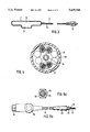
- FIG. 5a A front view of the plug showing the ventilation hose outlet.
- FIG. 5b A top view of the cable with the cable plug and the end of the ventilation hose at one end and the cable bushing with conductors and ventilating hoses at the other end.
- FIG. 6 A diagrammatic representation with a separate ventilating hose guide.
- FIG. 7a A cross-section through a cable with a cavity used for ventilating.
- FIG. 7b A cross-section through a cable with a cable ventilation opening in the cable jacket.
- FIG. 8a Another embodiment with a ventilating hose bonded together with the cable.
- FIG. 8b An embodiment with a ventilating hose extruded together with the cable jacket.
- FIG. 9a An embodiment with a separate ventilating hose guided in the cable plug.
- FIG. 9b An embodiment with a separate ventilating hose which terminates in the vicinity of the cable plug.
- FIG. 1 shows the principle of tocometry on the abdominal cavity 1, under which is located the uterus 2, which contracts in the direction of the arrow.
- a ram 3 On the abdominal wall 1 is placed a ram 3, which records the force through the uterine contraction and transmits it to a dynamometer 4.
- the signals converted by the dynamometer 4 are transmitted by means of a cable 5 to a monitoring device 6 having a recorder.
- FIG. 2 shows a transducer 7 for recording the measured values for the monitoring device 6, which has a transducer casing 8, which is given a watertight construction by means of an allround seal 9.
- the underside 10 of the transducer casing 8, which is placed on the abdominal wall 1, has a soft diaphragm 11 made from an elastomeric plastic.
- the ram 3 On said diaphragm 11 is placed the ram 3, which is connected to the dynamometer 4.
- the complete interior 12 of the transducer casing 8 is sealed against the penetration of water and makes available a specific air volume.
- the connection of the cable 5 takes place by means of the opening 23.
- a ventilating hose 14 which at one end with the cable bushing 13 passes into the interior 12 of the transducer casing 8. At the other end the ventilating hose 14 is guided in the cable plug and terminates in the vicinity of the socket of said plug. Therefore there is a ventilation possibility for the interior 12 as a result of said ventilating hose 14 and simultaneously there is no risk of water or the like passing into the interior 12 of the transducer 7.
- FIG. 4 shows in section a cable 5 with the cable jacket 16, screened conductors 17, filling material 18 and the ventilating hose 14.
- a thin Teflon tube with an internal diameter of approximately 0.9 mm and an external diameter of approximately 1.5 mm is also processed therewith.
- the ventilating hose 14 can run concentrically or eccentrically in the cable 5, which can contain one or more conductors 17.
- FIG. 5a is a front view of the plug with the contact pins 19 and the end of the ventilating hose 14.
- FIG. 5b shows the cable 5 in a technical embodiment with the cable plug 15 and the end of the ventilating hose 14 at one end, as well as the cable bushing 13 and the led out conductors 17 and ventilating hose 14 at the other end. Both ends of the cable 5 are moulded, a cable sleeve 22 being moulded onto the side which is introduced into the transducer 7.
- the ventilating hose 14 projects a few millimeters out of the cable end and into the transducer 7. At the other side the cable plug 15 is moulded on and the ventilating hose 14 is led out through a suitable opening.
- FIG. 6 diagrammatically shows an embodiment in which the ventilating hose 14 is separate from the cable 5.
- FIG. 7a shows the cross-section through a cable 5 with the cable jacket 16, screened conductors 17 and filling material 18, in which the cavity 20 is used for ventilating the interior 12 of the transducer 7.
- FIG. 7b shows the cable of FIG. 7a with a cable ventilation opening 21 in the cable jacket 16, which is to be installed as far away as possible from the transducer 7, so as to ensure that no water or the like can pass into the cavity 20 and therefore into the interior 12.
- FIGS. 8a and 8b show two embodiments with a ventilating hose 14, which can either be bonded together with the cable (FIG. 8a), or extruded together with the cable jacket 16 (FIG. 8b).
- FIG. 9 shows the passage of a separate ventilating hose 14 in the vicinity of the cable plug 15.
- the ventilating hose 14 is guided in the cable plug and connected therein, in the manner described hereinbefore.
- the ventilating hose 14 terminates in the open in the vicinity of the cable plug 15.
Abstract
Description
Claims (9)
Applications Claiming Priority (2)
| Application Number | Priority Date | Filing Date | Title |
|---|---|---|---|
| DE4408409.9 | 1994-03-12 | ||
| DE4408409A DE4408409C2 (en) | 1994-03-12 | 1994-03-12 | Sensor |
Publications (1)
| Publication Number | Publication Date |
|---|---|
| US5649548A true US5649548A (en) | 1997-07-22 |
Family
ID=6512617
Family Applications (1)
| Application Number | Title | Priority Date | Filing Date |
|---|---|---|---|
| US08/388,811 Expired - Fee Related US5649548A (en) | 1994-03-12 | 1995-02-15 | Transducer for monitoring labor pains |
Country Status (4)
| Country | Link |
|---|---|
| US (1) | US5649548A (en) |
| JP (1) | JPH07275211A (en) |
| DE (1) | DE4408409C2 (en) |
| GB (1) | GB2287323B (en) |
Cited By (2)
| Publication number | Priority date | Publication date | Assignee | Title |
|---|---|---|---|---|
| CN103961114A (en) * | 2014-05-09 | 2014-08-06 | 广州三瑞医疗器械有限公司 | Uterine contraction pressure sensor protecting device and method |
| US9295821B2 (en) | 2008-07-02 | 2016-03-29 | Christoph Miethke | Cerebrospinal fluid drainage |
Families Citing this family (3)
| Publication number | Priority date | Publication date | Assignee | Title |
|---|---|---|---|---|
| GB2385922A (en) * | 2002-01-29 | 2003-09-03 | Oxford Instr Medical Ltd | Device for monitoring uterine contractions using strain gauges |
| JP6969832B1 (en) * | 2021-06-01 | 2021-11-24 | 和之 横田 | Strain gauge transducer |
| WO2022255156A1 (en) * | 2021-06-01 | 2022-12-08 | 和之 横田 | Strain gauge transducer |
Citations (6)
| Publication number | Priority date | Publication date | Assignee | Title |
|---|---|---|---|---|
| WO1986003115A1 (en) * | 1984-11-30 | 1986-06-05 | Graeme John Clare | Tocodynamometers |
| US4640295A (en) * | 1985-11-14 | 1987-02-03 | Aequitron Medical, Inc. | Tocodynamometer |
| US4873986A (en) * | 1987-04-01 | 1989-10-17 | Utah Medical Products | Disposable apparatus for monitoring intrauterine pressure and fetal heart rate |
| DD275397A1 (en) * | 1988-09-12 | 1990-01-24 | Messgeraetewerk Zwonitz Veb K | TRANSFORMERS FOR THE EXTERNAL COLLECTION OF WEALTH |
| US4944307A (en) * | 1988-08-22 | 1990-07-31 | The Hon Group | Intrauterine catheter |
| US5184619A (en) * | 1986-11-10 | 1993-02-09 | Peritronics Medical, Inc. | Intrauterine pressure and fetal heart rate sensor |
Family Cites Families (1)
| Publication number | Priority date | Publication date | Assignee | Title |
|---|---|---|---|---|
| WO1980000054A1 (en) * | 1978-06-16 | 1980-01-24 | H Czerny | Measurement signal transmitter for continuous watching of the mother and the child before and during child birth |
-
1994
- 1994-03-12 DE DE4408409A patent/DE4408409C2/en not_active Expired - Fee Related
-
1995
- 1995-02-15 US US08/388,811 patent/US5649548A/en not_active Expired - Fee Related
- 1995-02-27 GB GB9503881A patent/GB2287323B/en not_active Expired - Fee Related
- 1995-03-10 JP JP7079927A patent/JPH07275211A/en active Pending
Patent Citations (6)
| Publication number | Priority date | Publication date | Assignee | Title |
|---|---|---|---|---|
| WO1986003115A1 (en) * | 1984-11-30 | 1986-06-05 | Graeme John Clare | Tocodynamometers |
| US4640295A (en) * | 1985-11-14 | 1987-02-03 | Aequitron Medical, Inc. | Tocodynamometer |
| US5184619A (en) * | 1986-11-10 | 1993-02-09 | Peritronics Medical, Inc. | Intrauterine pressure and fetal heart rate sensor |
| US4873986A (en) * | 1987-04-01 | 1989-10-17 | Utah Medical Products | Disposable apparatus for monitoring intrauterine pressure and fetal heart rate |
| US4944307A (en) * | 1988-08-22 | 1990-07-31 | The Hon Group | Intrauterine catheter |
| DD275397A1 (en) * | 1988-09-12 | 1990-01-24 | Messgeraetewerk Zwonitz Veb K | TRANSFORMERS FOR THE EXTERNAL COLLECTION OF WEALTH |
Cited By (3)
| Publication number | Priority date | Publication date | Assignee | Title |
|---|---|---|---|---|
| US9295821B2 (en) | 2008-07-02 | 2016-03-29 | Christoph Miethke | Cerebrospinal fluid drainage |
| CN103961114A (en) * | 2014-05-09 | 2014-08-06 | 广州三瑞医疗器械有限公司 | Uterine contraction pressure sensor protecting device and method |
| CN103961114B (en) * | 2014-05-09 | 2016-01-20 | 广州三瑞医疗器械有限公司 | A kind of palace pressure sensor protector and method thereof |
Also Published As
| Publication number | Publication date |
|---|---|
| DE4408409C2 (en) | 1996-04-11 |
| GB2287323B (en) | 1998-03-25 |
| DE4408409A1 (en) | 1995-09-14 |
| GB9503881D0 (en) | 1995-04-19 |
| GB2287323A (en) | 1995-09-13 |
| JPH07275211A (en) | 1995-10-24 |
Similar Documents
| Publication | Publication Date | Title |
|---|---|---|
| US4944307A (en) | Intrauterine catheter | |
| US4543965A (en) | Method and device for measuring intrauterine pressure | |
| US4785822A (en) | Disposable intracompartmental pressure transducer | |
| US4723555A (en) | Multi-functional radio/wire stethoscopic apparatus | |
| US6115624A (en) | Multiparameter fetal monitoring device | |
| US4873986A (en) | Disposable apparatus for monitoring intrauterine pressure and fetal heart rate | |
| US6434418B1 (en) | Apparatus for measuring intrauterine pressure and fetal heart rate and method for using same | |
| EP0094791A3 (en) | Ultrasonic endoscope having elongated array mounted in manner allowing it to remain flexible | |
| DE3267508D1 (en) | Combined endoscope and ultrasonic diagnostic device | |
| US4989615A (en) | Apparatus for non-invasive monitoring of uterine contractions | |
| US5218972A (en) | Biomedical force measuring apparatus | |
| EP2772188A3 (en) | Cable monitoring apparatus | |
| US5649548A (en) | Transducer for monitoring labor pains | |
| JP3883001B2 (en) | Intrauterine fetal monitoring device | |
| EP0317049A2 (en) | Ultrasonic probe | |
| JPH02241442A (en) | Ultrasonic apparatus for detecting pregnancy of female large animal | |
| CN111000587A (en) | Clinical fetus-voice meter for obstetrics and gynecology department | |
| CN210158701U (en) | Probe sheath of electronic fetal monitor | |
| US11779301B2 (en) | Blood flow probe, blood flow sensor, and blood flow measuring instrument | |
| ES8700923A1 (en) | Echo sounder head for testing gestation on animals. | |
| JPH02203837A (en) | Intrauterine catheter | |
| JPH0111213Y2 (en) | ||
| JP3283079B2 (en) | Ultrasound endoscope tip | |
| SU1243692A1 (en) | Apparatus for continuous of recording uterine contractions | |
| JPS63234956A (en) | Ultrasonic probe for body cavity |
Legal Events
| Date | Code | Title | Description |
|---|---|---|---|
| AS | Assignment |
Owner name: HEWLETT-PACKARD COMPANY, CALIFORNIA Free format text: ASSIGNMENT OF ASSIGNORS INTEREST;ASSIGNOR:HEWLETT-PACKARD COMPANY;REEL/FRAME:007355/0887 Effective date: 19950213 |
|
| FEPP | Fee payment procedure |
Free format text: PAYOR NUMBER ASSIGNED (ORIGINAL EVENT CODE: ASPN); ENTITY STATUS OF PATENT OWNER: LARGE ENTITY |
|
| AS | Assignment |
Owner name: HEWLETT-PACKARD COMPANY, A DELAWARE CORPORATION, C Free format text: MERGER;ASSIGNOR:HEWLETT-PACKARD COMPANY, A CALIFORNIA CORPORATION;REEL/FRAME:010841/0649 Effective date: 19980520 |
|
| AS | Assignment |
Owner name: AGILENT TECHNOLOGIES INC, CALIFORNIA Free format text: ASSIGNMENT OF ASSIGNORS INTEREST;ASSIGNOR:HEWLETT-PACKARD COMPANY;REEL/FRAME:010977/0540 Effective date: 19991101 |
|
| FPAY | Fee payment |
Year of fee payment: 4 |
|
| REMI | Maintenance fee reminder mailed | ||
| LAPS | Lapse for failure to pay maintenance fees | ||
| STCH | Information on status: patent discontinuation |
Free format text: PATENT EXPIRED DUE TO NONPAYMENT OF MAINTENANCE FEES UNDER 37 CFR 1.362 |
|
| FP | Lapsed due to failure to pay maintenance fee |
Effective date: 20050722 |
|
| AS | Assignment |
Owner name: KONINKLIJKE PHILIPS ELECTRONICS N V, NETHERLANDS Free format text: ASSIGNMENT OF ASSIGNORS INTEREST;ASSIGNOR:AGILENT TECHNOLOGIES, INC.;REEL/FRAME:022835/0572 Effective date: 20090610 |