US5636243A - Interterminal direct communication in digital mobile communication system - Google Patents
Interterminal direct communication in digital mobile communication system Download PDFInfo
- Publication number
- US5636243A US5636243A US08/494,289 US49428995A US5636243A US 5636243 A US5636243 A US 5636243A US 49428995 A US49428995 A US 49428995A US 5636243 A US5636243 A US 5636243A
- Authority
- US
- United States
- Prior art keywords
- timing signal
- accordance
- intermittently
- transmitter
- terminal
- Prior art date
- Legal status (The legal status is an assumption and is not a legal conclusion. Google has not performed a legal analysis and makes no representation as to the accuracy of the status listed.)
- Expired - Fee Related
Links
Images


Classifications
-
- H—ELECTRICITY
- H04—ELECTRIC COMMUNICATION TECHNIQUE
- H04W—WIRELESS COMMUNICATION NETWORKS
- H04W56/00—Synchronisation arrangements
- H04W56/001—Synchronization between nodes
- H04W56/002—Mutual synchronization
-
- H—ELECTRICITY
- H04—ELECTRIC COMMUNICATION TECHNIQUE
- H04M—TELEPHONIC COMMUNICATION
- H04M1/00—Substation equipment, e.g. for use by subscribers
- H04M1/72—Mobile telephones; Cordless telephones, i.e. devices for establishing wireless links to base stations without route selection
- H04M1/725—Cordless telephones
- H04M1/72502—Cordless telephones with one base station connected to a single line
- H04M1/72505—Radio link set-up procedures
- H04M1/72513—On hold, intercom or transfer communication modes
-
- H—ELECTRICITY
- H04—ELECTRIC COMMUNICATION TECHNIQUE
- H04B—TRANSMISSION
- H04B1/00—Details of transmission systems, not covered by a single one of groups H04B3/00 - H04B13/00; Details of transmission systems not characterised by the medium used for transmission
- H04B1/06—Receivers
- H04B1/16—Circuits
- H04B1/1607—Supply circuits
- H04B1/1615—Switching on; Switching off, e.g. remotely
-
- H—ELECTRICITY
- H04—ELECTRIC COMMUNICATION TECHNIQUE
- H04W—WIRELESS COMMUNICATION NETWORKS
- H04W92/00—Interfaces specially adapted for wireless communication networks
- H04W92/16—Interfaces between hierarchically similar devices
- H04W92/18—Interfaces between hierarchically similar devices between terminal devices
-
- Y—GENERAL TAGGING OF NEW TECHNOLOGICAL DEVELOPMENTS; GENERAL TAGGING OF CROSS-SECTIONAL TECHNOLOGIES SPANNING OVER SEVERAL SECTIONS OF THE IPC; TECHNICAL SUBJECTS COVERED BY FORMER USPC CROSS-REFERENCE ART COLLECTIONS [XRACs] AND DIGESTS
- Y02—TECHNOLOGIES OR APPLICATIONS FOR MITIGATION OR ADAPTATION AGAINST CLIMATE CHANGE
- Y02D—CLIMATE CHANGE MITIGATION TECHNOLOGIES IN INFORMATION AND COMMUNICATION TECHNOLOGIES [ICT], I.E. INFORMATION AND COMMUNICATION TECHNOLOGIES AIMING AT THE REDUCTION OF THEIR OWN ENERGY USE
- Y02D30/00—Reducing energy consumption in communication networks
- Y02D30/70—Reducing energy consumption in communication networks in wireless communication networks
-
- Y—GENERAL TAGGING OF NEW TECHNOLOGICAL DEVELOPMENTS; GENERAL TAGGING OF CROSS-SECTIONAL TECHNOLOGIES SPANNING OVER SEVERAL SECTIONS OF THE IPC; TECHNICAL SUBJECTS COVERED BY FORMER USPC CROSS-REFERENCE ART COLLECTIONS [XRACs] AND DIGESTS
- Y10—TECHNICAL SUBJECTS COVERED BY FORMER USPC
- Y10S—TECHNICAL SUBJECTS COVERED BY FORMER USPC CROSS-REFERENCE ART COLLECTIONS [XRACs] AND DIGESTS
- Y10S370/00—Multiplex communications
- Y10S370/915—Time division cellular radio systems
Definitions
- the present invention relates to a digital mobile communication system, and more specifically to direct communication between mobile terminals without intervention of a base station.
- Interterminal direct communication is one of most useful features of a digital cordless telephone which is called PHS (Personal Handy phone System).
- PHS Personal Handy phone System
- connection control and communication between mobile terminals are performed on a certain time slot of a communication channel (RCR STD-28: Research & Development Center for Radio Systems Standards 28). Therefore, the mobile terminals need to repeat a scan of all the communication channels for detection of an unique word (or a synchronization word) to be synchronized with each other.
- a calling mobile terminal finds an idle channel, and then transmits a connection control signal continuously for a predetermined period of time, while waiting for a response signal through the same channel. After the calling party and the called party are synchronized, the well-known connection sequence proceeds.
- the above-mentioned conventional PHS terminal repeats a scan of all the channels and , when it originates a call, the control signal is transmitted continuously. Since such an operation causes power consumption to increase, the battery incorporated in the terminal runs down in a short time.
- each of the terminal detects an intermittent timing signal from a predetermined control channel of the base station. Based on a timing signal synchronizing with the intermittent timing signal, a terminal intermittently exchanges signaling information with another terminal through an idle channel to establish synchronization therebetween.
- a calling-party terminal first detects a idle channel from predetermined channels and then intermittently transmits a control signal to a called-party terminal through the detected channel in accordance with a timing signal synchronizing with the intermittent timing signal.
- the called-party terminal first detects the channel used by the calling-party terminal in accordance with the timing signal synchronizing with the intermittent timing signal.
- the called party terminal intermittently receives the control signal from the calling-party terminal through the channel in accordance with the timing signal, and then intermittently transmits a response signal to the control signal to the calling-party terminal through the channel in accordance with the timing signal. In this way, synchronization between the terminals is established.
- each the terminal power is intermittently supplied to a transmitter and a receiver in accordance with the timing signal. Since power is supplied at the time of transmitting or receiving, reduced power consumption and battery-saving is achieved in the course of handshaking.
- FIG. 1 is a schematic diagram showing a PHS communication system used in an embodiment of an interterminal communication method according to the present invention
- FIG. 2 is a schematic diagram showing a frequency channel arrangement for explanation of an operation of the embodiment
- FIG. 3 is a diagram showing a superframe format of a logical control channel employed in the embodiment
- FIG. 4 is a diagram showing a time slot format of the logical control channel as shown in FIG. 3;
- FIG. 5 is a block diagram illustrating a schematic circuit arrangement of a PHS terminal according to an embodiment of the present invention
- FIG. 6 is a block diagram illustrating a more detailed circuit arrangement of the PHS terminal as shown in FIG. 5;
- FIG. 7 is a circuit diagram of the power supplying controller of FIG. 6;
- FIG. 8 is a flowchart showing a start-up operation of the PHS terminal
- FIG. 9 is a flowchart showing an operation of a calling-party PHS terminal
- FIG. 10 is a flowchart showing an operation of a called-party terminal
- FIG. 11 is a timing chart showing an operation of the power supply controller in the intermittent receiving mode
- FIG. 12 is a timing chart showing an operation of the power supply controller in the intermittent transmitting mode.
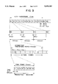
- FIG. 13 is a timing chart showing a handshaking operation of two PHS terminals.
- a base station 101 is connected to a network 102 and mobile terminals 103 and 104 are located in a service area of the base station 101.
- the base station 101 performs intermittent transmission of control signals through a downgoing control channel (downgoing CCH). Based on the timing of the downgoing CCH, a control signal and a response signal are intermittently transmitted between the mobile terminals 103 and 104 for handshake. After the synchronization is established between the mobile terminals 103 and 104, direct communication therebetween is performed through a certain time slot.
- downgoing CCH downgoing control channel
- the base station 101 transmits the control signals to the whole service area intermittently through the frequency channel #1. Synchronizing with the intermittent timing of the downgoing CCH, the mobile terminals 103 and 104 transmit control signals for handshake to each other through a certain time slot of a certain frequency channel, for example, the frequency channel #3.
- FIG. 3 shows a superframe format of a logical control channel (LCCH) employed in the embodiment.
- a LCCH superframe has a period of 1.2 sec and consists of 12 intermittent transmission slots each having a period of 100 msec.
- Each intermittent transmission slot consists of 20 TDMA frames each having a period of 5 msec.
- the first slot of a TDMA frame is assigned to LCCH. Therefore, the mobile terminals 103 and 104 receive control signals from the base station 101 at intervals of 100 msec.
- a time slot format is shown in FIG. 4.
- Respective functional channels are identified by the channel indicator (CI) in a time slot.
- FIG. 5 shows a schematic circuit of a PHS mobile station according to an embodiment of the present invention.
- a PHS mobile terminal 201 an antenna 202 is connected to a receiver 203 and a transmitter 204.
- the receiver 203 outputs a demodulated signal to a control channel detector 205 which detects the control channel CCH transmitted by the base station 101 and extracts the intermittent timing T cch (100 msec cycle) therefrom.
- the intermittent timing T cch is transferred to a controller 206 which generates a timing control signal Tc to output it to a timing generator 207.
- the controller 206 controls the entire operation of the mobile terminal including power supplying, receiving and transmitting operations.
- the timing generator 207 Synchronizing with the intermittent timing T cch , the timing generator 207 generates an intermittent transmission/receive timing T t/r (5 msec cycle), and outputs it back to the controller 206.
- a power supplying controller 209 controls power supplying to the receiver 203 and the transmitter 204 in accordance with control of the controller 206 and the intermittent timing T t/r .
- a more detailed circuit of the mobile terminal 201 will be described hereinafter.
- an antenna 301 is connected to the receiver and the transmitter through an antenna switch 302.
- the receiver is comprised of a low-noise amplifier 303, a mixer 304, a demodulator 305 and a frequency synthesizer 306.
- Receiving a high-frequency wave from the antenna 301 the receiver converts it to receiving data Dr which are demodulated by the demodulator 305.
- Local oscillation signals for down-converting and demodulating are supplied to the mixer 304 and the demodulator 305 by the frequency synthesizer 306.
- the receiving data Dr is input to a TDMA sync controller 307.
- the TDMA sync controller 307 detects any functional channel, intermittent timing T cch of the control channel CCH, TDMA frame timing (5 ms FRM) and other necessary data to select voice data D v for this terminal from the receiving data D r . Further, according to control signals S r and S t received from a controller 313, the TDMA sync controller 307 outputs a receive control signal S tr and a transmission control signal S tt to the receiver and the transmitter, respectively.
- the voice data D v is decoded into an acoustic signal by the coder-decoder (CODEC) 308, and the acoustic signal is converted into sound waves by a speaker.
- a transmitting acoustic signal is output from a microphone to the CODEC 308 which encodes it into a transmitting voice data D v .
- the TDMA sync controller 307 assembles TDMA time slot signals from the transmitting voice data, and outputs the transmitting data D t to the transmitter.
- the transmitter is comprised of a modulator 309, a mixer 310, a frequency synthesizer 311, and a transmission power amplifier 312.
- Local oscillation signals for modulation and up-converting are supplied to the modulator 309 and the mixer 310 by the frequency synthesizer 311.
- the modulator 309 modulates the local oscillation signal for modulation according to the transmitting data D t .
- the resultant modulated wave is up-converted by the mixer 310 mixing the modulated wave with the local oscillation signal for up-converting.
- the transmitting wave up-converted is amplified in power by the transmission power amplifier 312.
- the controller 313 receives the intermittent timing T cch and the TDMA frame sync signal from the TDMA sync controller 307, and outputs a timing control signal Tc to the timing generator comprising a PLL(Phase-Locked Loop) controller 314 and a digital PLL clock generator 315.
- the PLL controller 314 receives the timing control signal Tc from the controller 313, the PLL controller 314 outputs a reference timing signal T ref and a fixed coefficient N to the PLL clock generator 315.
- the reference timing signal T ref synchronizes with the intermittent timing T cch .
- the PLL clock generator 315 generates the intermittent transmission/receive timing T ref according to the reference timing signal T ref and the fixed coefficient N.
- the intermittent timing T cch has a cycle of 100 msec and the intermittent transmission/receive timing T t/r has a cycle of 5 msec.
- the intermittent timing T t/r is output to the controller 313 as well as a power supplying controller 316.
- the controller 313 generates the transmission control signal S t , the receive control signal S r and a selection signal S t/r based on the intermittent timing T t/r .
- the control signals S t and S r are output to the TDMA sync controller 307 and the selection signal S t/r is output to the power supplying controller 316.
- a battery 317 supplies power to a DC-DC converter 318 which outputs adjusted power to the power supplying controller 316.
- the power supplying controller 316 supplies power to the receiver and/or the transmitter in accordance with the selection signal S t/r and the intermittent timing T t/r .
- the power supplying controller 316 is comprised of switching circuits SW1 and SW2 which are controlled by a switch controller 319 receiving the intermittent timing T t/r from the PLL clock generator 315. Power is transferred to the receiver through the switching circuit SW1 and to the transmitter through the switching circuit SW2.
- the switch controller 319 selects both or one of the switching circuits SW1 and SW2 according to the selection signal S t/r .
- a switching circuit selected performs a switching operation on the power supply according to the intermittent timing T t/r .
- the power supplying controller 316 supplies power to the receiver and other necessary circuits.
- the receiving data D r is transferred from the receiver to the TDMA sync controller 307.
- the TDMA sync controller 307 extracts the intermittent timing T cch from the control channel CCH and outputs it to the controller 313 (S402).
- the controller 313 outputs the timing control signal Tc to the PLL controller 314 which further outputs the fixed coefficient N and the reference timing T ref synchronizing with the intermittent timing T cch to the PLL clock generator 315.
- the PLL clock generator 315 generates the intermittent receive-timing T r which has a cycle of 5 msec and is phase-locked to T ref (S403).
- the intermittent receive-timing T r is output to the controller 313 and the power supplying controller 316.
- the controller 313 outputs the control signal S r to the TDMA sync controller 307 which further outputs the receive-timing control signal S tr to the receiver.
- the power supplying controller 316 supplies power Pr to the receiver with the power Pr switching on and off in accordance with the intermittent receive-timing T r (see FIG. 11). Therefore, the receiver performs the intermittent receiving operation according to the intermittent receive-timing T r , which is referred to as an intermittent receiving mode (S404).
- the TDMA sync controller 307 searches for an idle time slot according to the intermittent receive-timing T r received from the PLL clock generator 315 (S502, S503). If an idle time slot, e.g. a transmitting time slot #T2, is found (Yes in S503), the controller 313 controls the PLL clock generator 315 such that an intermittent transmission-timing T t having a cycle of 5 msec is generated in accordance with the intermittent receive-timing T r (S504).
- an idle time slot e.g. a transmitting time slot #T2
- the controller 313 outputs the control signal S t to the TDMA sync controller 307 which further outputs the transmission-timing control signal S tt to the transmitter.
- the power supplying controller 316 supplies power Pt to the transmitter with the power Pt switching on and off in accordance with the intermittent transmission-timing T t (see FIG. 12). Therefore, the transmitter performs the intermittent transmitting operation according to the intermittent transmission-timing T t , which is referred to as an intermittent transmitting mode (S505).
- the TDMA sync controller 307 assembles the TDMA data of the control signal in the idle time slot (e.g. #T2) and the transmitter transmits the data to a called party-terminal through the time slot (S506).
- a response signal is received from the called-party terminal (Yes in S507), synchronization between the terminals is established (S508). After that, the well-known call setup sequence is followed to make communication with each other.
- the transmission power amplifier 312 consumes a large amount of power, the longer the transmission power amplifier 312 works, the sooner the battery 317 runs down.
- the power Pt is supplied to the transmitter only when the transmitting burst signal is transmitted through a time slot of 625 ⁇ sec having a cycle of 5 msec. Therefore, such an intermittent transmitting mode results in substantial battery-saving.
- the controller 313 searches for the control channel or the time slot used by the calling-party terminal. More specifically, the controller 313 causes the PLL clock generator 315 to change the intermittent receive-timing T r in time slots while changing the receiving control signal S r . Following the receiving control signal S r , the TDMA sync controller 307 controls the synthesizer 306 of the receiver so as to scan the frequency channels (S603).
- the controller 313 causes the PLL clock generator 315 to generate the intermittent transmission-timing T t synchronizing with the control channel detected (S605).
- the power supplying controller 316 supplies power Pt to the transmitter and the TDMA sync controller 307 assembles a response signal to the control signal and transfers it as transmitting data Dt to the transmitter from which the response signal is transmitted to the calling-party terminal (S606). In this way, the synchronization between the terminals is established (S607).
- FIGS. 11 and 12 show an intermittent receiving and transmitting modes in the case where the time slot #2 is used, respectively.
- the power supplying controller 316 supplies the power Pr to the receiver only at the timing of the time slot #R2 and the power Pt to the transmitter only at the timing of the time slot #T2.
- FIG. 13 is a time chart which shows receiving and transmitting timing in communications between two mobile terminals A and B.
- the terminals A and B are both performing the CCH intermittent receiving operation mentioned above in the timing (701) synchronizing with the control channel CCH of the nearest base station.
- the terminal B searches for an idle slot and transmits a control signal to the terminal A through the channel of the idle slot (703).
- the terminal A when some receiving signal is detected, the terminal A, as mentioned above, scanning all the time slots to search for the channel used by the terminal B.
- the terminal A transmits a response signal to the terminal B through the channel. Synchronization between the terminals is established when the terminal B receives the response signal from the terminal A (705). After handshaking, usual communication is made between the terminals A and B.
- a control signal and a response signal thereto are intermittently transmitted and received for handshaking based on the timing of the control channel CCH which a nearest base station is transmitting.
- power is also supplied to the transmitter and the receiver intermittently, resulting in lower power consumption and the battery-saving.
Abstract
Description
Claims (10)
Applications Claiming Priority (2)
| Application Number | Priority Date | Filing Date | Title |
|---|---|---|---|
| JP6165955A JPH0819041A (en) | 1994-06-25 | 1994-06-25 | Communication method between slave sets in digital cordless telephone system and digital cordless telephone set |
| JP6-165955 | 1994-06-25 |
Publications (1)
| Publication Number | Publication Date |
|---|---|
| US5636243A true US5636243A (en) | 1997-06-03 |
Family
ID=15822199
Family Applications (1)
| Application Number | Title | Priority Date | Filing Date |
|---|---|---|---|
| US08/494,289 Expired - Fee Related US5636243A (en) | 1994-06-25 | 1995-06-23 | Interterminal direct communication in digital mobile communication system |
Country Status (3)
| Country | Link |
|---|---|
| US (1) | US5636243A (en) |
| JP (1) | JPH0819041A (en) |
| GB (1) | GB2290677B (en) |
Cited By (69)
| Publication number | Priority date | Publication date | Assignee | Title |
|---|---|---|---|---|
| US5737325A (en) * | 1994-12-09 | 1998-04-07 | Sony Corporation | Connection method of digital cordless telephone apparatus |
| US5778311A (en) * | 1995-06-30 | 1998-07-07 | Matsushita Electric Industrial Co., Ltd. | Intermittent operation receiver with variable pre-heat time for its phase-locked circuit |
| US5802472A (en) * | 1995-09-06 | 1998-09-01 | Nec Corporation | Reconnection apparatus in direct communication system between subsidiary radiotelephone units |
| US5828704A (en) * | 1996-04-12 | 1998-10-27 | Nec Corporation | Radio selective calling receiver |
| US5857145A (en) * | 1996-08-02 | 1999-01-05 | Nec Corporation | Radio pager |
| EP0921668A2 (en) * | 1997-08-14 | 1999-06-09 | Samsung Electronics Co., Ltd. | TDMA communication method and system |
| US5949764A (en) * | 1997-11-21 | 1999-09-07 | Vlsi Technology, Inc. | Conference call on a personal handy phone system portable station |
| US5978367A (en) * | 1995-08-14 | 1999-11-02 | Nokia Telecommunications Oy | Synchronizing a telecommunications connection in a mobile communications system |
| US6016331A (en) * | 1997-08-05 | 2000-01-18 | Vlsi Technology, Inc. | Methods of synchronization, personal handy-phone system stations and phase lock loops |
| US6026297A (en) * | 1997-09-17 | 2000-02-15 | Telefonaktiebolaget Lm Ericsson | Contemporaneous connectivity to multiple piconets |
| US6049532A (en) * | 1997-05-30 | 2000-04-11 | Motorola, Inc. | Method of and apparatus for reducing a power consumption of a communication device |
| US6088338A (en) * | 1995-04-21 | 2000-07-11 | Siemens Information And Communication Networks S.P.A. | Method and system for the determination of the PSCN parameter starting from the MFN parameter in a DECT cordless telephone system |
| US6115367A (en) * | 1997-08-05 | 2000-09-05 | Vlsi Technology, Inc. | Methods of analyzing a radio signal and methods of analyzing a personal handy-phone system radio signal |
| US6115612A (en) * | 1996-06-25 | 2000-09-05 | Sony Corporation | Wireless telephone system having a free period allocated to switching between two frequencies |
| US6134424A (en) * | 1996-10-04 | 2000-10-17 | Kabushiki Kaisha Toshiba | High-frequency power amplifier and mobile communication device using same |
| US6144656A (en) * | 1995-08-14 | 2000-11-07 | Nokia Telecommunications Oy | Synchronizing a telecommunications connection in a mobile communications system |
| WO2001001717A1 (en) * | 1999-06-25 | 2001-01-04 | Telefonaktiebolaget Lm Ericsson (Publ) | Base-station-assisted terminal-to-terminal connection setup |
| US6178447B1 (en) * | 1998-07-16 | 2001-01-23 | Alcatel | Telecommunications network receiver |
| US6304560B1 (en) | 1997-09-30 | 2001-10-16 | Vlsi Technology, Inc. | Personal handy-phone system wireless local loops and methods of transmitting information within personal handy-phone systems |
| US6332086B2 (en) * | 1997-04-07 | 2001-12-18 | Graham Avis | Discontinuous receive operation in a wireless terminal |
| US6339711B1 (en) * | 1997-03-14 | 2002-01-15 | Kabushiki Kaisha Toshiba | Radio apparatus |
| US6381233B1 (en) * | 1996-03-25 | 2002-04-30 | Yrp Mobile Telecommunications Key Technology Research Laboratories Co., Ltd. | Spread spectrum communication transmitter and receiver, and CDMA mobile communication system and method |
| US6415157B1 (en) * | 1998-08-28 | 2002-07-02 | Nec Corporation | Personal handyphone system (PHS) mobile radio station with efficient resynchronization capability |
| US20020085520A1 (en) * | 2001-01-04 | 2002-07-04 | Uwe Sydon | Cordless communication system providing optimum spectral usage for wireless networks |
| US6466562B1 (en) | 1997-12-29 | 2002-10-15 | Koninklijke Philips Electronics N.V. | Data communication devices, personal handy-phone system base stations, and methods of communicating data |
| US6484027B1 (en) | 1998-06-15 | 2002-11-19 | Sbc Technology Resources, Inc. | Enhanced wireless handset, including direct handset-to-handset communication mode |
| US6532369B1 (en) * | 1999-08-20 | 2003-03-11 | Lucent Technologies Inc. | System and method for mobile controlled direct mode wireless local calling |
| US20030050083A1 (en) * | 1999-12-13 | 2003-03-13 | Jean-Pierre Metais | Method for controlling a communications channel shared by several stations |
| US6577619B2 (en) * | 1997-03-27 | 2003-06-10 | Nokia Corporation | Packet transmission in mobile telecommunications systems |
| US20030147367A1 (en) * | 2000-08-03 | 2003-08-07 | Pucheu Gerard Marque | Method and device for synchronising mobile terminals on a radio channel in direct mode |
| WO2003075586A1 (en) | 2002-03-06 | 2003-09-12 | Koninklijke Philips Electronics N.V. | Method to reduce power consumption in a radio communication system and apparatus therefor |
| US20030185170A1 (en) * | 2002-03-27 | 2003-10-02 | Allen Vernon Anthony | System and method for asynchronous and communications employing direct indirect access protocols |
| US6650630B1 (en) | 1999-06-25 | 2003-11-18 | Telefonaktiebolaget Lm Ericsson (Publ) | Resource management and traffic control in time-division-duplex communication systems |
| US20030231597A1 (en) * | 2002-05-23 | 2003-12-18 | Hester Lance Eric | Quality of service (QoS) control mechanisms using mediation devices in an asynchronous network |
| US6671292B1 (en) | 1999-06-25 | 2003-12-30 | Telefonaktiebolaget Lm Ericsson (Publ) | Method and system for adaptive voice buffering |
| US6693968B1 (en) * | 1999-06-02 | 2004-02-17 | Motorola, Inc. | Digital portable or mobile radio |
| US6693891B1 (en) * | 1998-02-27 | 2004-02-17 | Sony Corporation | Communication control method and transmission unit |
| US20040042501A1 (en) * | 2002-05-23 | 2004-03-04 | Hester Lance Eric | Media access control and distributed data processing using mediation devices in an asynchronous network |
| US20040057548A1 (en) * | 1994-03-18 | 2004-03-25 | Silicon Integrated System Corp. | Quasi-synchronous multi-stage event synchronization apparatus |
| US20040147277A1 (en) * | 1994-07-21 | 2004-07-29 | Interdigital Technology Corporation | Subscriber terminal temperature regulation |
| WO2004091238A1 (en) * | 2003-04-11 | 2004-10-21 | Koninklijke Philips Electronics N.V. | A method and apparatus for supporting p2p communication in tdd cdma communication systems |
| WO2004102833A1 (en) * | 2003-05-19 | 2004-11-25 | Koninklijke Philips Electronics N.V. | A method and apparatus for uplink synchronization maintenance with p2p communication in wireless communication networks |
| US20040266425A1 (en) * | 2003-06-24 | 2004-12-30 | Sbc, Inc. | Wireless wide area network charger and cradle |
| US20050054335A1 (en) * | 2003-09-04 | 2005-03-10 | Sbc Knowledge Ventures, L.P. | Call forwarding control device and method of call management |
| US20050063528A1 (en) * | 2003-09-23 | 2005-03-24 | Sbc Knowledge Ventures, L.P. | Location based call routing for call answering services |
| US20050064853A1 (en) * | 2003-09-23 | 2005-03-24 | Sbc Knowledge Ventures, L.P. | Unified telephone handset for personal communications based on wireline and wireless network convergence |
| US20050064855A1 (en) * | 2003-09-23 | 2005-03-24 | Sbc Knowledge Ventures, L.P. | Method and system for forwarding wireless communications |
| US20050096024A1 (en) * | 2003-11-05 | 2005-05-05 | Sbc Knowledge Ventures, L.P. | System and method of transitioning between cellular and voice over internet protocol communication |
| US20050215210A1 (en) * | 2004-03-24 | 2005-09-29 | Harmonic Design, Inc. | Low power rf control system |
| US20050277431A1 (en) * | 2004-06-14 | 2005-12-15 | Sbc Knowledge Ventures, Lp | System and method for managing wireless data communications |
| US20060003806A1 (en) * | 2004-07-02 | 2006-01-05 | Sbc Knowledge Ventures, L.P. | Phone synchronization device and method of handling personal information |
| US7039445B1 (en) * | 1999-11-18 | 2006-05-02 | Kabushiki Kaisha Toshiba | Communication system, communication apparatus, and communication method |
| US20060153105A1 (en) * | 2003-03-07 | 2006-07-13 | Koninklijke Philips Electronics N.V. | Maintaining uplink control via the interception of signals for mobile terminals in direct mode peer-to-peer communication |
| US20060178148A1 (en) * | 2003-04-01 | 2006-08-10 | Yonggang Du | Method and system for peer-to-peer communication management in wireless communication networks |
| US20060258382A1 (en) * | 2003-05-19 | 2006-11-16 | Xuejen Zhang | Method and apparatus for supporting p2p communication in tdd cdma communication systems |
| US20070230394A1 (en) * | 2006-03-24 | 2007-10-04 | Interdigital Technology Corporation | Method and apparatus for maintaining uplink synchronization and reducing battery power consumption |
| US20070298738A1 (en) * | 2006-06-27 | 2007-12-27 | Motorola, Inc. | Method for managing scanning of channels in a wireless network |
| US20080032625A1 (en) * | 2006-07-19 | 2008-02-07 | David Cheung | Deviating from a transmission map to communicate in a wireless network |
| US20090161655A1 (en) * | 2007-12-20 | 2009-06-25 | Qualcomm, Incorporated | Umb cell site modem architecture and methods |
| WO2009078005A2 (en) * | 2007-12-14 | 2009-06-25 | Full Spectrum, Inc. | A system and method for the delivery of high speed data services over dedicated and non-dedicated private land mobile radio (plmr) channels using cognitive radio technology |
| US8005204B2 (en) | 2005-06-03 | 2011-08-23 | At&T Intellectual Property I, L.P. | Call routing system and method of using the same |
| US8280030B2 (en) | 2005-06-03 | 2012-10-02 | At&T Intellectual Property I, Lp | Call routing system and method of using the same |
| US20140070962A1 (en) * | 2012-09-13 | 2014-03-13 | Kim Tamar Holland | Emergency Vehicle Warning System and Method |
| US8751232B2 (en) | 2004-08-12 | 2014-06-10 | At&T Intellectual Property I, L.P. | System and method for targeted tuning of a speech recognition system |
| US8824659B2 (en) | 2005-01-10 | 2014-09-02 | At&T Intellectual Property I, L.P. | System and method for speech-enabled call routing |
| US20140287682A1 (en) * | 2013-01-30 | 2014-09-25 | Kabushiki Kaisha Toshiba | Communication device and communication method |
| CN104412646A (en) * | 2012-08-03 | 2015-03-11 | 英特尔公司 | Communication path switching for mobile devices |
| US9112972B2 (en) | 2004-12-06 | 2015-08-18 | Interactions Llc | System and method for processing speech |
| US20190007908A1 (en) * | 2014-02-21 | 2019-01-03 | Mitsubishi Australia Limited | Data communication device and method |
Families Citing this family (11)
| Publication number | Priority date | Publication date | Assignee | Title |
|---|---|---|---|---|
| US6243399B1 (en) | 1994-07-21 | 2001-06-05 | Interdigital Technology Corporation | Ring signal generator |
| FI100159B (en) * | 1995-01-19 | 1997-09-30 | Nokia Telecommunications Oy | Synchronization of a telecommunication connection in a mobile communication system |
| SE505209C2 (en) * | 1995-02-08 | 1997-07-14 | Telia Ab | Procedure for increasing the traffic capacity of a wireless communication system |
| FI97582C (en) * | 1995-03-03 | 1997-01-10 | Nokia Telecommunications Oy | Synchronization of a mobile station broadcast |
| GB9513398D0 (en) * | 1995-06-30 | 1995-09-27 | Boateng Jacob K | Automatic exchangeless universal radio phone |
| US5854784A (en) * | 1996-11-05 | 1998-12-29 | Ericsson, Inc. | Power-saving method for providing synchronization in a communications system |
| JPH11177479A (en) | 1997-12-15 | 1999-07-02 | Nec Corp | Input signal scanner for radio telephone set and its method |
| GB2411080B (en) * | 2004-02-14 | 2006-06-21 | Motorola Inc | Wireless communication terminal, system and method |
| FR2903849B1 (en) * | 2006-07-12 | 2008-12-26 | Sagem Comm | CURRENT CALL SEARCHING METHOD AND DEVICE BY A RECEIVING MOBILE STATION OF A TIME DIVISION MULTIPLE ACCESS MOBILE TELEPHONY SYSTEM. |
| US8320398B2 (en) | 2007-07-10 | 2012-11-27 | Qualcomm Incorporated | Paging a peer in a peer-to-peer communication network |
| US8706145B2 (en) | 2007-07-10 | 2014-04-22 | Qualcomm Incorporated | Multihop paging of a peer in a peer-to-peer communication network |
Citations (5)
| Publication number | Priority date | Publication date | Assignee | Title |
|---|---|---|---|---|
| GB2226934A (en) * | 1988-08-19 | 1990-07-11 | Gary David Cooper | Radio communication system |
| GB2279849A (en) * | 1993-06-02 | 1995-01-11 | Vtech Communications Ltd | Method of conducting an intercom communication between two cordless telephone handsets |
| US5428638A (en) * | 1993-08-05 | 1995-06-27 | Wireless Access Inc. | Method and apparatus for reducing power consumption in digital communications devices |
| GB2285723A (en) * | 1994-01-18 | 1995-07-19 | Motorola Ltd | Direct TDMA communication between mobiles |
| US5570369A (en) * | 1994-03-15 | 1996-10-29 | Nokia Mobile Phones Limited | Reduction of power consumption in a mobile station |
Family Cites Families (2)
| Publication number | Priority date | Publication date | Assignee | Title |
|---|---|---|---|---|
| JP2653004B2 (en) * | 1991-07-31 | 1997-09-10 | 日本電気株式会社 | Wireless communication system |
| EP0689303A1 (en) * | 1994-05-25 | 1995-12-27 | Alcatel Bell-Sdt S.A. | TDMA mobile communication system with simultaneous communication between base and mobiles at a first frequency and between mobiles at a second one |
-
1994
- 1994-06-25 JP JP6165955A patent/JPH0819041A/en active Pending
-
1995
- 1995-06-23 US US08/494,289 patent/US5636243A/en not_active Expired - Fee Related
- 1995-06-26 GB GB9512988A patent/GB2290677B/en not_active Expired - Fee Related
Patent Citations (5)
| Publication number | Priority date | Publication date | Assignee | Title |
|---|---|---|---|---|
| GB2226934A (en) * | 1988-08-19 | 1990-07-11 | Gary David Cooper | Radio communication system |
| GB2279849A (en) * | 1993-06-02 | 1995-01-11 | Vtech Communications Ltd | Method of conducting an intercom communication between two cordless telephone handsets |
| US5428638A (en) * | 1993-08-05 | 1995-06-27 | Wireless Access Inc. | Method and apparatus for reducing power consumption in digital communications devices |
| GB2285723A (en) * | 1994-01-18 | 1995-07-19 | Motorola Ltd | Direct TDMA communication between mobiles |
| US5570369A (en) * | 1994-03-15 | 1996-10-29 | Nokia Mobile Phones Limited | Reduction of power consumption in a mobile station |
Cited By (134)
| Publication number | Priority date | Publication date | Assignee | Title |
|---|---|---|---|---|
| US20040057548A1 (en) * | 1994-03-18 | 2004-03-25 | Silicon Integrated System Corp. | Quasi-synchronous multi-stage event synchronization apparatus |
| US20040147277A1 (en) * | 1994-07-21 | 2004-07-29 | Interdigital Technology Corporation | Subscriber terminal temperature regulation |
| US5737325A (en) * | 1994-12-09 | 1998-04-07 | Sony Corporation | Connection method of digital cordless telephone apparatus |
| US6088338A (en) * | 1995-04-21 | 2000-07-11 | Siemens Information And Communication Networks S.P.A. | Method and system for the determination of the PSCN parameter starting from the MFN parameter in a DECT cordless telephone system |
| US5778311A (en) * | 1995-06-30 | 1998-07-07 | Matsushita Electric Industrial Co., Ltd. | Intermittent operation receiver with variable pre-heat time for its phase-locked circuit |
| US5978367A (en) * | 1995-08-14 | 1999-11-02 | Nokia Telecommunications Oy | Synchronizing a telecommunications connection in a mobile communications system |
| US6144656A (en) * | 1995-08-14 | 2000-11-07 | Nokia Telecommunications Oy | Synchronizing a telecommunications connection in a mobile communications system |
| US5802472A (en) * | 1995-09-06 | 1998-09-01 | Nec Corporation | Reconnection apparatus in direct communication system between subsidiary radiotelephone units |
| US6381233B1 (en) * | 1996-03-25 | 2002-04-30 | Yrp Mobile Telecommunications Key Technology Research Laboratories Co., Ltd. | Spread spectrum communication transmitter and receiver, and CDMA mobile communication system and method |
| USRE40997E1 (en) * | 1996-03-25 | 2009-11-24 | Mitsubishi Denki Kabushiki Kaisha | Spread spectrum communication transmitter and receiver, and CDMA mobile communication system and method |
| US5828704A (en) * | 1996-04-12 | 1998-10-27 | Nec Corporation | Radio selective calling receiver |
| AU715197B2 (en) * | 1996-04-12 | 2000-01-20 | Nec Corporation | Radio selective calling receiver |
| US6115612A (en) * | 1996-06-25 | 2000-09-05 | Sony Corporation | Wireless telephone system having a free period allocated to switching between two frequencies |
| US5857145A (en) * | 1996-08-02 | 1999-01-05 | Nec Corporation | Radio pager |
| US6134424A (en) * | 1996-10-04 | 2000-10-17 | Kabushiki Kaisha Toshiba | High-frequency power amplifier and mobile communication device using same |
| US6339711B1 (en) * | 1997-03-14 | 2002-01-15 | Kabushiki Kaisha Toshiba | Radio apparatus |
| US6577619B2 (en) * | 1997-03-27 | 2003-06-10 | Nokia Corporation | Packet transmission in mobile telecommunications systems |
| US6332086B2 (en) * | 1997-04-07 | 2001-12-18 | Graham Avis | Discontinuous receive operation in a wireless terminal |
| US6049532A (en) * | 1997-05-30 | 2000-04-11 | Motorola, Inc. | Method of and apparatus for reducing a power consumption of a communication device |
| US6115367A (en) * | 1997-08-05 | 2000-09-05 | Vlsi Technology, Inc. | Methods of analyzing a radio signal and methods of analyzing a personal handy-phone system radio signal |
| US6016331A (en) * | 1997-08-05 | 2000-01-18 | Vlsi Technology, Inc. | Methods of synchronization, personal handy-phone system stations and phase lock loops |
| US6198784B1 (en) | 1997-08-05 | 2001-03-06 | Vlsi Technology, Inc. | Methods of synchronizing a personal handy-phone system station and phase lock loops |
| EP0921668A2 (en) * | 1997-08-14 | 1999-06-09 | Samsung Electronics Co., Ltd. | TDMA communication method and system |
| EP0921668A3 (en) * | 1997-08-14 | 2001-07-11 | Samsung Electronics Co., Ltd. | TDMA communication method and system |
| US6026297A (en) * | 1997-09-17 | 2000-02-15 | Telefonaktiebolaget Lm Ericsson | Contemporaneous connectivity to multiple piconets |
| US6304560B1 (en) | 1997-09-30 | 2001-10-16 | Vlsi Technology, Inc. | Personal handy-phone system wireless local loops and methods of transmitting information within personal handy-phone systems |
| US5949764A (en) * | 1997-11-21 | 1999-09-07 | Vlsi Technology, Inc. | Conference call on a personal handy phone system portable station |
| US6466562B1 (en) | 1997-12-29 | 2002-10-15 | Koninklijke Philips Electronics N.V. | Data communication devices, personal handy-phone system base stations, and methods of communicating data |
| US6693891B1 (en) * | 1998-02-27 | 2004-02-17 | Sony Corporation | Communication control method and transmission unit |
| US20050020236A1 (en) * | 1998-06-15 | 2005-01-27 | Sbc, Inc. | Enhanced wireless handset, including direct handset-to-handset communication mode |
| US20110124316A1 (en) * | 1998-06-15 | 2011-05-26 | Bertrum Technologies Llc | Enhanced wireless handset, including direct handset-to-handset communication mode |
| US7353018B2 (en) | 1998-06-15 | 2008-04-01 | Bertrum Technologies Llc | Enhanced wireless handset, including direct handset-to-handset communication mode |
| US7403793B2 (en) | 1998-06-15 | 2008-07-22 | Bertrum Technologies Llc | Enhanced wireless handset, including direct handset-to-handset communication mode |
| US7693542B2 (en) | 1998-06-15 | 2010-04-06 | Daniel Wayne Mauney | Enhanced wireless handset, including direct handset-to-handset communication mode |
| US20100178869A1 (en) * | 1998-06-15 | 2010-07-15 | Bertrum Technologies Llc | Enhanced wireless handset, including direct handset-to-handset communication mode |
| US9503840B2 (en) | 1998-06-15 | 2016-11-22 | Intellectual Ventures I Llc | Enhanced wireless handset, including direct handset-to-handset communication mode |
| US7885684B2 (en) | 1998-06-15 | 2011-02-08 | Bertrum Technologies Llc | Enhanced wireless handset, including direct handset-to-handset communication mode |
| US8792828B2 (en) | 1998-06-15 | 2014-07-29 | Bertrum Technologies Llc | Enhanced wireless handset, including direct handset-to-handset communication mode |
| US8019381B2 (en) | 1998-06-15 | 2011-09-13 | Bertrum Technologies Llc | Enhanced wireless handset, including direct handset-to-handset communication mode |
| US20050032475A1 (en) * | 1998-06-15 | 2005-02-10 | Sbc, Inc. | Enhanced wireless handset, including direct handset-to-handset communication mode |
| US6484027B1 (en) | 1998-06-15 | 2002-11-19 | Sbc Technology Resources, Inc. | Enhanced wireless handset, including direct handset-to-handset communication mode |
| US8346169B2 (en) | 1998-06-15 | 2013-01-01 | Bertrum Technologies Llc | Enhanced wireless handset, including direct handset-to-handset communication mode |
| US6865372B2 (en) * | 1998-06-15 | 2005-03-08 | Sbc Technology Resources, Inc. | Enhanced wireless handset, including direct handset-to-handset communication mode |
| US20040116073A1 (en) * | 1998-06-15 | 2004-06-17 | Sbc, Inc. | Enhanced wireless handset, including direct handset-to-handset communication mode |
| US8265691B2 (en) | 1998-06-15 | 2012-09-11 | Bertrum Technologies Llc | Enhanced wireless handset, including direct handset-to-handset communication mode |
| US6178447B1 (en) * | 1998-07-16 | 2001-01-23 | Alcatel | Telecommunications network receiver |
| US6415157B1 (en) * | 1998-08-28 | 2002-07-02 | Nec Corporation | Personal handyphone system (PHS) mobile radio station with efficient resynchronization capability |
| US6693968B1 (en) * | 1999-06-02 | 2004-02-17 | Motorola, Inc. | Digital portable or mobile radio |
| US6671292B1 (en) | 1999-06-25 | 2003-12-30 | Telefonaktiebolaget Lm Ericsson (Publ) | Method and system for adaptive voice buffering |
| WO2001001717A1 (en) * | 1999-06-25 | 2001-01-04 | Telefonaktiebolaget Lm Ericsson (Publ) | Base-station-assisted terminal-to-terminal connection setup |
| US20050048985A1 (en) * | 1999-06-25 | 2005-03-03 | Telefonaktiebolaget Lm Ericsson (Publ) | Resource management and traffic control in time-division-duplex communication systems |
| US7313123B2 (en) | 1999-06-25 | 2007-12-25 | Telefonaktiebolaget L M Ericsson (Publ) | Resource management and traffic control in time-division-duplex communication systems |
| US6574266B1 (en) | 1999-06-25 | 2003-06-03 | Telefonaktiebolaget Lm Ericsson (Publ) | Base-station-assisted terminal-to-terminal connection setup |
| US6650630B1 (en) | 1999-06-25 | 2003-11-18 | Telefonaktiebolaget Lm Ericsson (Publ) | Resource management and traffic control in time-division-duplex communication systems |
| US6532369B1 (en) * | 1999-08-20 | 2003-03-11 | Lucent Technologies Inc. | System and method for mobile controlled direct mode wireless local calling |
| US7039445B1 (en) * | 1999-11-18 | 2006-05-02 | Kabushiki Kaisha Toshiba | Communication system, communication apparatus, and communication method |
| US20030050083A1 (en) * | 1999-12-13 | 2003-03-13 | Jean-Pierre Metais | Method for controlling a communications channel shared by several stations |
| US7136663B2 (en) * | 1999-12-13 | 2006-11-14 | Eads Secure Networks | Method for controlling a communications channel shared by several stations |
| US20030147367A1 (en) * | 2000-08-03 | 2003-08-07 | Pucheu Gerard Marque | Method and device for synchronising mobile terminals on a radio channel in direct mode |
| US7529223B2 (en) * | 2000-08-03 | 2009-05-05 | Eads Defence And Security Networks | Method and device for synchronising mobile terminals on a radio channel in direct mode |
| US20020085520A1 (en) * | 2001-01-04 | 2002-07-04 | Uwe Sydon | Cordless communication system providing optimum spectral usage for wireless networks |
| US20050096101A1 (en) * | 2002-03-06 | 2005-05-05 | Sayers Anthony D. | Method to reduce power consumption in a radio communication system and apparatus therefor |
| US7546090B2 (en) * | 2002-03-06 | 2009-06-09 | Koninklijke Philips Electronics N.V. | Method to reduce power consumption in a radio communication system and apparatus therefor |
| WO2003075586A1 (en) | 2002-03-06 | 2003-09-12 | Koninklijke Philips Electronics N.V. | Method to reduce power consumption in a radio communication system and apparatus therefor |
| CN1640163B (en) * | 2002-03-06 | 2012-06-20 | 皇家飞利浦电子股份有限公司 | Method to reduce power consumption in a radio communication system and apparatus therefor |
| US7133398B2 (en) * | 2002-03-27 | 2006-11-07 | Motorola, Inc. | System and method for asynchronous communications employing direct and indirect access protocols |
| US20030185170A1 (en) * | 2002-03-27 | 2003-10-02 | Allen Vernon Anthony | System and method for asynchronous and communications employing direct indirect access protocols |
| US20030231597A1 (en) * | 2002-05-23 | 2003-12-18 | Hester Lance Eric | Quality of service (QoS) control mechanisms using mediation devices in an asynchronous network |
| US20040042501A1 (en) * | 2002-05-23 | 2004-03-04 | Hester Lance Eric | Media access control and distributed data processing using mediation devices in an asynchronous network |
| US7492773B2 (en) | 2002-05-23 | 2009-02-17 | Motorola, Inc. | Media access control and distributed data processing using mediation devices in an asynchronous network |
| US7440462B2 (en) | 2002-05-23 | 2008-10-21 | Motorola, Inc. | Quality of service (QOS) control mechanisms using mediation devices in an asynchronous network |
| US20060153105A1 (en) * | 2003-03-07 | 2006-07-13 | Koninklijke Philips Electronics N.V. | Maintaining uplink control via the interception of signals for mobile terminals in direct mode peer-to-peer communication |
| US7308266B2 (en) * | 2003-04-01 | 2007-12-11 | Koninklijke Philips Electronics, N.V. | Method and system for peer-to-peer communication management in wireless communication networks |
| US20060178148A1 (en) * | 2003-04-01 | 2006-08-10 | Yonggang Du | Method and system for peer-to-peer communication management in wireless communication networks |
| WO2004091238A1 (en) * | 2003-04-11 | 2004-10-21 | Koninklijke Philips Electronics N.V. | A method and apparatus for supporting p2p communication in tdd cdma communication systems |
| US7286842B2 (en) * | 2003-04-11 | 2007-10-23 | Koninklijke Philips Electronics, N.V. | Method and apparatus for supporting direct link communication in TDD CDMA system |
| US20060245398A1 (en) * | 2003-04-11 | 2006-11-02 | Yueheng Li | Method and apparatus for supporting direct link communication in tdd cdma system |
| US20060258382A1 (en) * | 2003-05-19 | 2006-11-16 | Xuejen Zhang | Method and apparatus for supporting p2p communication in tdd cdma communication systems |
| US7333824B2 (en) * | 2003-05-19 | 2008-02-19 | Koninklijke Philips Electronics N.V. | Method and apparatus for supporting P2P communication in TDD CDMA communication systems |
| CN1792048B (en) * | 2003-05-19 | 2012-05-23 | 皇家飞利浦电子股份有限公司 | A method and device for uplink synchronization maintenance with P2P communication in wireless communication networks |
| US20060258383A1 (en) * | 2003-05-19 | 2006-11-16 | Cheng Jiang | Method and apparatus for uplink synchronization maintenance with p2p communication in wireless communication networks |
| WO2004102833A1 (en) * | 2003-05-19 | 2004-11-25 | Koninklijke Philips Electronics N.V. | A method and apparatus for uplink synchronization maintenance with p2p communication in wireless communication networks |
| US7336638B2 (en) | 2003-05-19 | 2008-02-26 | Koninklijke Philips Electronics N.V. | Method and apparatus for uplink synchronization maintenance with P2P communication in wireless communication networks |
| US20040266425A1 (en) * | 2003-06-24 | 2004-12-30 | Sbc, Inc. | Wireless wide area network charger and cradle |
| US20050054335A1 (en) * | 2003-09-04 | 2005-03-10 | Sbc Knowledge Ventures, L.P. | Call forwarding control device and method of call management |
| US8027700B2 (en) | 2003-09-23 | 2011-09-27 | At&T Intellectual Property I, L.P. | Method and system for forwarding communications |
| US20050063528A1 (en) * | 2003-09-23 | 2005-03-24 | Sbc Knowledge Ventures, L.P. | Location based call routing for call answering services |
| US7769392B2 (en) | 2003-09-23 | 2010-08-03 | At&T Intellectual Property I, L.P. | Method and system for forwarding wireless communications |
| US20100240343A1 (en) * | 2003-09-23 | 2010-09-23 | At&T Intellectual Property I, L.P. | Method and System for Forwarding Communications |
| US8526977B2 (en) | 2003-09-23 | 2013-09-03 | At&T Intellectual Property I, L.P. | Location based call routing for call answering services |
| US20050064855A1 (en) * | 2003-09-23 | 2005-03-24 | Sbc Knowledge Ventures, L.P. | Method and system for forwarding wireless communications |
| US20050064853A1 (en) * | 2003-09-23 | 2005-03-24 | Sbc Knowledge Ventures, L.P. | Unified telephone handset for personal communications based on wireline and wireless network convergence |
| US7885657B2 (en) | 2003-11-05 | 2011-02-08 | At&T Intellectual Property I, L.P. | System and method of transitioning between cellular and voice over internet protocol communication |
| US20090238147A1 (en) * | 2003-11-05 | 2009-09-24 | At&T Intellectual Property I, L.P. | System and Method of Transitioning Between Cellular and Voice Over Internet Protocol Communication |
| US7577427B2 (en) | 2003-11-05 | 2009-08-18 | At&T Intellectual Property I, L.P. | System and method of transitioning between cellular and voice over internet protocol communication |
| US20050096024A1 (en) * | 2003-11-05 | 2005-05-05 | Sbc Knowledge Ventures, L.P. | System and method of transitioning between cellular and voice over internet protocol communication |
| US20100279639A1 (en) * | 2004-03-24 | 2010-11-04 | Somfy Sas | Low power rf control system |
| US7860481B2 (en) | 2004-03-24 | 2010-12-28 | Somfy Sas | Low power rf control system |
| US7783277B2 (en) * | 2004-03-24 | 2010-08-24 | Somfy Sas | Low power rf control system |
| US20050215210A1 (en) * | 2004-03-24 | 2005-09-29 | Harmonic Design, Inc. | Low power rf control system |
| US20050277431A1 (en) * | 2004-06-14 | 2005-12-15 | Sbc Knowledge Ventures, Lp | System and method for managing wireless data communications |
| US20060003806A1 (en) * | 2004-07-02 | 2006-01-05 | Sbc Knowledge Ventures, L.P. | Phone synchronization device and method of handling personal information |
| US9368111B2 (en) | 2004-08-12 | 2016-06-14 | Interactions Llc | System and method for targeted tuning of a speech recognition system |
| US8751232B2 (en) | 2004-08-12 | 2014-06-10 | At&T Intellectual Property I, L.P. | System and method for targeted tuning of a speech recognition system |
| US9112972B2 (en) | 2004-12-06 | 2015-08-18 | Interactions Llc | System and method for processing speech |
| US9350862B2 (en) | 2004-12-06 | 2016-05-24 | Interactions Llc | System and method for processing speech |
| US8824659B2 (en) | 2005-01-10 | 2014-09-02 | At&T Intellectual Property I, L.P. | System and method for speech-enabled call routing |
| US9088652B2 (en) | 2005-01-10 | 2015-07-21 | At&T Intellectual Property I, L.P. | System and method for speech-enabled call routing |
| US8280030B2 (en) | 2005-06-03 | 2012-10-02 | At&T Intellectual Property I, Lp | Call routing system and method of using the same |
| US8619966B2 (en) | 2005-06-03 | 2013-12-31 | At&T Intellectual Property I, L.P. | Call routing system and method of using the same |
| US8005204B2 (en) | 2005-06-03 | 2011-08-23 | At&T Intellectual Property I, L.P. | Call routing system and method of using the same |
| US10764857B2 (en) | 2006-03-24 | 2020-09-01 | Interdigital Technology Corporation | Method and apparatus for maintaining uplink synchronization and reducing battery power consumption |
| US10433271B2 (en) | 2006-03-24 | 2019-10-01 | Interdigital Technology Corporation | Method and apparatus for maintaining uplink synchronization and reducing battery power consumption |
| US9900857B2 (en) | 2006-03-24 | 2018-02-20 | Interdigital Technology Corporation | Method and apparatus for maintaining uplink synchronization and reducing battery power consumption |
| US9167546B2 (en) | 2006-03-24 | 2015-10-20 | Interdigital Technology Corporation | Method and apparatus for providing discontinuous reception (DRX) |
| US20070230394A1 (en) * | 2006-03-24 | 2007-10-04 | Interdigital Technology Corporation | Method and apparatus for maintaining uplink synchronization and reducing battery power consumption |
| US11711777B2 (en) | 2006-03-24 | 2023-07-25 | Interdigital Technology Corporation | Method and apparatus for maintaining uplink synchronization and reducing battery power consumption |
| US11871371B2 (en) | 2006-03-24 | 2024-01-09 | Interdigital Technology Corporation | Method and apparatus for maintaining uplink synchronization and reducing battery power consumption |
| US7620397B2 (en) * | 2006-06-27 | 2009-11-17 | Motorola, Inc. | Method for managing scanning of channels in a wireless network |
| US20070298738A1 (en) * | 2006-06-27 | 2007-12-27 | Motorola, Inc. | Method for managing scanning of channels in a wireless network |
| US7760694B2 (en) * | 2006-07-19 | 2010-07-20 | Intel Corporation | Deviating from a transmission map to communicate in a wireless network |
| US20080032625A1 (en) * | 2006-07-19 | 2008-02-07 | David Cheung | Deviating from a transmission map to communicate in a wireless network |
| WO2009078005A2 (en) * | 2007-12-14 | 2009-06-25 | Full Spectrum, Inc. | A system and method for the delivery of high speed data services over dedicated and non-dedicated private land mobile radio (plmr) channels using cognitive radio technology |
| US8619804B2 (en) | 2007-12-14 | 2013-12-31 | Full Spectrum Inc. | System and method for the delivery of high speed data services over dedicated and non-dedicated private land mobile radio (PLMR) channels using cognitive radio technology |
| US20100303033A1 (en) * | 2007-12-14 | 2010-12-02 | Menashe Shahar | System and method for the delivery of high speed data services over dedicated and non-dedicated private land mobile radio (plmr) channels using cognitive radio technology |
| WO2009078005A3 (en) * | 2007-12-14 | 2010-02-25 | Full Spectrum, Inc. | A system and method for the delivery of data over dedicated and non-dedicated private land mobile radio (plmr) channels |
| US20090161655A1 (en) * | 2007-12-20 | 2009-06-25 | Qualcomm, Incorporated | Umb cell site modem architecture and methods |
| CN104412646A (en) * | 2012-08-03 | 2015-03-11 | 英特尔公司 | Communication path switching for mobile devices |
| CN104412646B (en) * | 2012-08-03 | 2018-09-04 | 英特尔公司 | For the communication path switching of mobile device |
| US9111447B2 (en) * | 2012-09-13 | 2015-08-18 | Kim Tamar Holland | Emergency vehicle warning system and method |
| US20140070962A1 (en) * | 2012-09-13 | 2014-03-13 | Kim Tamar Holland | Emergency Vehicle Warning System and Method |
| US20140287682A1 (en) * | 2013-01-30 | 2014-09-25 | Kabushiki Kaisha Toshiba | Communication device and communication method |
| US20190007908A1 (en) * | 2014-02-21 | 2019-01-03 | Mitsubishi Australia Limited | Data communication device and method |
| US10820275B2 (en) * | 2014-02-21 | 2020-10-27 | Avcatech Pty Ltd | Data communication device and method |
Also Published As
| Publication number | Publication date |
|---|---|
| GB2290677B (en) | 1998-07-22 |
| JPH0819041A (en) | 1996-01-19 |
| GB9512988D0 (en) | 1995-08-30 |
| GB2290677A (en) | 1996-01-03 |
Similar Documents
| Publication | Publication Date | Title |
|---|---|---|
| US5636243A (en) | Interterminal direct communication in digital mobile communication system | |
| US5748621A (en) | Digital mobile communication system | |
| JPH0629910A (en) | Inter radio base station synchronization system | |
| JP3034282B2 (en) | Asynchronous mobile radio communication system | |
| JPH08204683A (en) | Method and equipment for direct communication in tdma radiocommunication system | |
| US6104937A (en) | Power-saving method and circuit | |
| US4744101A (en) | Cordless telephone system | |
| JPH09121385A (en) | Radio telephone set for cellular system | |
| JP2001028776A (en) | Hand-over method for mobile station for phs (registered trademark) | |
| US6198784B1 (en) | Methods of synchronizing a personal handy-phone system station and phase lock loops | |
| JPH0775165A (en) | Digital cordless telephone system | |
| JPH09163432A (en) | Radio communication system | |
| JP2977312B2 (en) | Mobile radio communication system | |
| JPH10276477A (en) | Cordless telephone system | |
| JPH0984117A (en) | Slave set and master set for cordless telephone device and cordless telephone device | |
| JPH0946759A (en) | Radio communication base station, radio communication terminal and radio communication method | |
| JP3738056B2 (en) | Cordless phone | |
| JPH1065600A (en) | Mobile communication equipment and radio line switch control method therefor | |
| JP2000286775A (en) | Direct communication method between mobile stations in radio communication system and mobile station using the communication method | |
| JP2510034B2 (en) | Connection control method for cordless phones | |
| JPH0787678A (en) | Communication device | |
| JPH11113054A (en) | Mobile radio terminal equipment and its control method | |
| JP2001245356A (en) | Mobile wireless phone | |
| JPH1094052A (en) | Communication equipment, communicator and communication method | |
| JPH11285072A (en) | Radio telephone device of tdma system |
Legal Events
| Date | Code | Title | Description |
|---|---|---|---|
| AS | Assignment |
Owner name: NEC CORPORATION, JAPAN Free format text: ASSIGNMENT OF ASSIGNORS INTEREST;ASSIGNOR:TANAKA, SYOICHI;REEL/FRAME:007566/0301 Effective date: 19950619 |
|
| FEPP | Fee payment procedure |
Free format text: PAYOR NUMBER ASSIGNED (ORIGINAL EVENT CODE: ASPN); ENTITY STATUS OF PATENT OWNER: LARGE ENTITY |
|
| FPAY | Fee payment |
Year of fee payment: 4 |
|
| FPAY | Fee payment |
Year of fee payment: 8 |
|
| REMI | Maintenance fee reminder mailed | ||
| LAPS | Lapse for failure to pay maintenance fees | ||
| STCH | Information on status: patent discontinuation |
Free format text: PATENT EXPIRED DUE TO NONPAYMENT OF MAINTENANCE FEES UNDER 37 CFR 1.362 |
|
| FP | Lapsed due to failure to pay maintenance fee |
Effective date: 20090603 |