US5634562A - Method and apparatus for separating, feeding and sorting - Google Patents
Method and apparatus for separating, feeding and sorting Download PDFInfo
- Publication number
- US5634562A US5634562A US08/480,458 US48045895A US5634562A US 5634562 A US5634562 A US 5634562A US 48045895 A US48045895 A US 48045895A US 5634562 A US5634562 A US 5634562A
- Authority
- US
- United States
- Prior art keywords
- product
- products
- feeder elements
- stack
- conveyor
- Prior art date
- Legal status (The legal status is an assumption and is not a legal conclusion. Google has not performed a legal analysis and makes no representation as to the accuracy of the status listed.)
- Expired - Fee Related
Links
Images


Classifications
-
- B—PERFORMING OPERATIONS; TRANSPORTING
- B65—CONVEYING; PACKING; STORING; HANDLING THIN OR FILAMENTARY MATERIAL
- B65G—TRANSPORT OR STORAGE DEVICES, e.g. CONVEYORS FOR LOADING OR TIPPING, SHOP CONVEYOR SYSTEMS OR PNEUMATIC TUBE CONVEYORS
- B65G43/00—Control devices, e.g. for safety, warning or fault-correcting
- B65G43/08—Control devices operated by article or material being fed, conveyed or discharged
-
- B—PERFORMING OPERATIONS; TRANSPORTING
- B07—SEPARATING SOLIDS FROM SOLIDS; SORTING
- B07C—POSTAL SORTING; SORTING INDIVIDUAL ARTICLES, OR BULK MATERIAL FIT TO BE SORTED PIECE-MEAL, e.g. BY PICKING
- B07C1/00—Measures preceding sorting according to destination
- B07C1/02—Forming articles into a stream; Arranging articles in a stream, e.g. spacing, orientating
- B07C1/04—Forming a stream from a bulk; Controlling the stream, e.g. spacing the articles
-
- B—PERFORMING OPERATIONS; TRANSPORTING
- B65—CONVEYING; PACKING; STORING; HANDLING THIN OR FILAMENTARY MATERIAL
- B65G—TRANSPORT OR STORAGE DEVICES, e.g. CONVEYORS FOR LOADING OR TIPPING, SHOP CONVEYOR SYSTEMS OR PNEUMATIC TUBE CONVEYORS
- B65G47/00—Article or material-handling devices associated with conveyors; Methods employing such devices
- B65G47/22—Devices influencing the relative position or the attitude of articles during transit by conveyors
- B65G47/26—Devices influencing the relative position or the attitude of articles during transit by conveyors arranging the articles, e.g. varying spacing between individual articles
- B65G47/28—Devices influencing the relative position or the attitude of articles during transit by conveyors arranging the articles, e.g. varying spacing between individual articles during transit by a single conveyor
-
- B—PERFORMING OPERATIONS; TRANSPORTING
- B65—CONVEYING; PACKING; STORING; HANDLING THIN OR FILAMENTARY MATERIAL
- B65G—TRANSPORT OR STORAGE DEVICES, e.g. CONVEYORS FOR LOADING OR TIPPING, SHOP CONVEYOR SYSTEMS OR PNEUMATIC TUBE CONVEYORS
- B65G47/00—Article or material-handling devices associated with conveyors; Methods employing such devices
- B65G47/22—Devices influencing the relative position or the attitude of articles during transit by conveyors
- B65G47/26—Devices influencing the relative position or the attitude of articles during transit by conveyors arranging the articles, e.g. varying spacing between individual articles
- B65G47/30—Devices influencing the relative position or the attitude of articles during transit by conveyors arranging the articles, e.g. varying spacing between individual articles during transit by a series of conveyors
- B65G47/31—Devices influencing the relative position or the attitude of articles during transit by conveyors arranging the articles, e.g. varying spacing between individual articles during transit by a series of conveyors by varying the relative speeds of the conveyors forming the series
-
- B—PERFORMING OPERATIONS; TRANSPORTING
- B65—CONVEYING; PACKING; STORING; HANDLING THIN OR FILAMENTARY MATERIAL
- B65G—TRANSPORT OR STORAGE DEVICES, e.g. CONVEYORS FOR LOADING OR TIPPING, SHOP CONVEYOR SYSTEMS OR PNEUMATIC TUBE CONVEYORS
- B65G2203/00—Indexing code relating to control or detection of the articles or the load carriers during conveying
- B65G2203/04—Detection means
- B65G2203/042—Sensors
-
- Y—GENERAL TAGGING OF NEW TECHNOLOGICAL DEVELOPMENTS; GENERAL TAGGING OF CROSS-SECTIONAL TECHNOLOGIES SPANNING OVER SEVERAL SECTIONS OF THE IPC; TECHNICAL SUBJECTS COVERED BY FORMER USPC CROSS-REFERENCE ART COLLECTIONS [XRACs] AND DIGESTS
- Y10—TECHNICAL SUBJECTS COVERED BY FORMER USPC
- Y10S—TECHNICAL SUBJECTS COVERED BY FORMER USPC CROSS-REFERENCE ART COLLECTIONS [XRACs] AND DIGESTS
- Y10S209/00—Classifying, separating, and assorting solids
- Y10S209/90—Sorting flat-type mail
Definitions
- This invention relates to the separating, feeding and sorting of flat packages, and more particularly to a method and apparatus for separating, feeding and sorting characterized by controlled movement of products through a transport path.
- a computer controlled conveyor mechanism characterized by an infeed conveyor belt, an inclined and tilted roller separator, an output conveyor belt, and a divert gate, receives stacked products at the upstream input end, separates the products into a single stream, determines if each qualifies for sorting and sorts the product into designated bins at the output end.
- the infeed conveyor belt receives bulk stacks of products from a human loader and transports the products downstream to a feed roller.
- a sensor at the upstream end of the separator controls access to the separator. When the sensor detects the absence of a product resting on the upstream edge of the separator, the computer directs the apparatus to automatically deliver more products to the separator by causing the infeed conveyor belt to jog forward and the feed roller to rotate.
- the separator consists of a series of individually and selectively controlled friction feeder rolls laterally tilted and arranged on an inclined plane.
- the inclination of the feeder rolls facilitates the use of gravitational forces to assist in separation of stacked and overlapping products.
- Rotation of the feeder rolls further assists the separation process by causing downstream movement of underlying products.
- the friction coefficient between the feeder rolls and the product is higher than that between two products and because of the angle of incline of the separator, the overlying products tend to slide in an upstream direction away from the underlying single product. Downstream movement of underlying products separates stacked products into a sequence of individual units.
- the computer monitors the location of each product on the separator and prevents "tailgating" of preceding products by maintaining a minimum distance between consecutive products.
- Each individual product is then propelled out of the separator onto the output conveyor belt.
- the lateral tilt of the feeder rolls causes each product to slide against one edge of the conveyor mechanism. This facilitates the sorting process at the output conveyor belt as described below
- a bar code scanner reads a bar code on each product and compares it to a list of reference bar codes stored in the control computer. Accurate bar code scanning and sorting is facilitated by the location of each separated product against the edge of the conveyor mechanism.
- the scanner has a narrow field of view and scanning accuracy is maximized by locating the separated products against the edge of the conveyor mechanism adjacent to the scanner.
- the output conveyor belt transports the separated products to a sorting divert gate. If the bar code scanner fails to find a bar code on a scanned product, the computer causes the divert gate to direct the product into a first bin where the operator may reprocess the product through the present invention. If the bar code matches a stored bar code, the computer causes a divert gate to direct the product to a selected bin where it is assembled for further processing. Thus, bulk stacks of products are sorted more accurately and efficiently than the manual systems presently in use.
- the automated separating, feeding and sorting apparatus of this invention may be adapted to process various stacks of flat packages with attached identifying bar codes. Possible applications include sorting of magazines, postal mail and warehouse inventory. Other advantages and applications deriving from the use of the invention will readily suggest themselves to those skilled in the art from consideration of the following detailed description taken in conjunction with the accompanying drawings.
- FIG. 1 is a perspective view of the separating, feeding and sorting apparatus in which parts have been cut away to more clearly illustrate certain features of the invention
- FIG. 2 is a side view of an individual feeder roll of the separator shown in FIG. 1;
- FIG. 3 is a front elevation of an individual feeder rolls as shown in FIG. 2 of the separator shown in FIG. 1;
- FIG. 4 is a partial perspective view of the apparatus of FIG. 1 showing the feeder rolls and feed roller;
- FIG. 5 is a partial side view of the apparatus of FIG. 1 showing the interrelation between the infeed conveyor belt, feed roller and feeder rolls;
- FIG. 6 is a side view of the separator illustrated in FIG. 4.
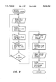
- FIGS. 7A, 7B, 8, 9, 10A and 10B are a flow diagrams illustrating one embodiment for controlling the individual feeder rolls to effectuate separation of stacked products into a sequence of individual products.
- the apparatus 30 defines a transport path illustrated in part by the arrows 32 and 34 and comprising an infeed conveyor belt 40, a feed roller 42, an inclined and laterally tilted separator 44, an output conveyor belt 46, and a divert gate 48.
- the apparatus 30 further includes a bar code scanner 50 and a central processing unit 60. The main operating components of the apparatus 30 are enclosed within a housing 90.
- the separator 44 consists of a series of individually and selectively controlled feeder rolls 52 arranged on a laterally tilted inclined plane.
- the central processing unit 60 through sensing means to be described, detects the position and movement of products on the separator 44, and in response energizes the feeder rolls 52 to effect separation of stacks of products into a sequence of individual products.
- the individual products After separation, the individual products continue to move downstream onto the output conveyor belt 46 where they are transported through a bar code scanner 50.
- the scanned bar codes are transmitted to the central processing unit 60 and the individual products are sorted by the divert gate 48 into designated receptacles (not shown) in response to control signals from the central processing unit 60.
- the bar code For each scanned product, the bar code is compared to a set of "reject" and "process” bar codes stored in the central processing unit 60. If the scanned bar code matches a stored "reject" bar code, the central processing unit 60 sends a signal to instruct the divert gate 48 to direct the product to a bin (not shown) where it is collected and either recycled or processed manually.
- the central processing unit 60 If the bar code matches a stored "process" code, the central processing unit 60 generates a signal to instruct the divert gate 48 to direct the product to a bin (not shown) for further processing. If the scanner fails to find a bar code the central processing unit 60 sends a signal to instruct the divert gate 48 to direct the product to a residual bin (not shown) where it is collected and sent back through the apparatus 30 for reprocessing.
- the central processing unit 60 preferably comprises a computer capable of directing all of the functions of the separating and sorting apparatus 30 in accordance with a software program that is a principal component therein.
- the aforementioned computer includes such features as an 80286 CPU, 640K RAM, 1.2 MB floppy disk, 20 MB hard disk, two serial ports and one parallel port.
- computers of this type are well known and the detailed construction of the computer itself does not form part of the present invention, further description of the computer is deemed unnecessary.
- Sort-and-tally software plans for each product are stored in ASCII data files located either on floppy disk or downloaded to the computer hard drive. Several thousand valid bar codes may be input for a given sort-and-tally software plan.
- the computer At the end of each run, the computer generates a report for each product that tallies the occurrences of each detected bar code. The report also tallies extraneous bar codes and indicates the total number of products that were diverted because of unreadable bar codes.
- the computer also performs data acquisition functions, either by means of the aforementioned bar code scanner 50 or by means of sensors to be described. Furthermore, the computer exercises control over the individual elements of the apparatus 30 by energizing the motors powering the infeed conveyor belt 40, feed roller 42, feeder rolls 52, output conveyor belt 46 and divert gate 48.
- the sensor for regulating entrance of products onto the separator 44 comprises a convergent beam photoelectric cell 80 connected to the central processing unit 60.
- Convergent beam photoelectric cell 80 detects distance changes between the cell and the object sensed, in this case a product 82.
- the cell 80 is positioned between the feed roller 42 and the upstream edge of the first feeder roll 52 of the separator 44. Because the feed roller 42 has a much larger diameter than the feeder rolls 52, product 82 does not immediately rest flush with the first feeder roll 52 as shown by the solid line product 82 in FIG. 5.
- the trailing edge of the product 82 falls on the first feeder roll 52 of the separator 44 as shown by the broken line product in FIG. 5.
- the cell 80 "shoots" an infrared sensing beam 84 that responds to the distance change between the solid and broken line product positions and transmits a signal indicative of this position change to the central processing unit 60. If the beam 84 from the cell 80 does not detect the broken line product position, then the central processing unit 60 knows that a product or group of products 82 is not present at the upstream edge of the separator 44. The central processing unit 60 then energizes the power motors for the infeed conveyor belt 40 and feed roller 42 allowing further products to enter the separator 44.
- the central processing unit 60 If the beam 84 of the cell 80 detects a broken line product position, the central processing unit 60 knows that there is sufficient product in position on the separator 44. The central processing unit 60 then de-energizes the power motors for the infeed conveyor belt 40 and feed roller 42 inhibiting further products from entering and crowding the separator 44. Operation of the input end of the separator 44 in this manner prevents overloading of the separator 44 permitting the separation process to occur more efficiently and effectively.
- the separator 44 includes a plurality of individually and selectively controlled feeder rolls 52 arranged on a laterally tilted inclined plane.
- Each feeder roll 52 is mounted in a frame 54.
- the drive mechanism for each feeder roll 52 is mounted on the frame 54 and comprises a motor 56.
- the motor 56 preferably is a constant speed D.C. electric motor.
- Mounted to the motor 56 is a pulley 58 driving a belt 64 to direct operating power to a second pulley 62 rotatively mounted on the frame 54.
- the second pulley 62 is mounted to the shaft supporting the feeder roll 52.
- a single motor 56 is utilized to actuate a pulley 58 which in-turn operates, through belt 64 and pulley 62, one feeder roll 52.
- the separator 44 has an inside and outside rail, 72 and 74 respectively, and has been laterally tilted with respect to the inside rail 72 and outside rail 74 so that the inside rail is at a lower horizontal elevation (approximately a 7° tilt) than the outside rail. Configuration of the separator 44 in this manner causes products to slide toward and ride next to the inside rail 72. Thus, at the discharge from the separator 44, the products are lined up in a single file against the inside rail 72. This facilitates a more accurate identification of the products by the bar code scanner 50 as described below.
- the separator 44 has also been longitudinally positioned to form an inclined plane. Configuration of the separator 44 in this manner allows for utilization of gravitational forces to assist separation of stacked products. Because the coefficient of friction between two stacked products is lower than that between the underlying product and the feeder rolls 52 and because of the angle of incline (approximately 22°) of the separator 44, the overlying products tend to slide backward separating the stack.
- the feeder rolls 52 are selectively and individually energized by the central processing unit 60, according to a program to be described, in response to position and movement information detected by an array of photoelectric cells 66 located over the inside rail 72 of the separator 44.
- Each feeder roll 52 has a corresponding photoelectric cell 66 to detect the presence or absence at that roll of the product being processed by the separator 44.
- the photoelectric cells 66 are positioned to detect an infrared beam 68 through the gap between individual feeder rolls 52 on the separator 44.
- the infrared beam 68 directed between rollers 52 is reflected by a retroreflector 70 and detected by the photoelectric cell 66.
- the central processing unit 60 scans the entire array of photoelectric cells 66 to find all shadows on the separator 44 and compares the information obtained to that stored from a previous scan. The central processing unit 60 thus determines the position and relative movement of all products on the separator 44 and decides whether a shadow indicates the presence of a stacked group or an individual product. From these determinations, the central processing unit selectively energizes individual feeder rolls or sets of feeder rolls to separate stacks of products into individual units.
- a subroutine for controlling the feeder rolls 52 is diagrammatically illustrated via a set of flowcharts.
- the subroutine is particularly directed to scanning the photoelectric cell array 66 and articulating individual feeder rolls or sets of feeder rolls to effectuate the separation of products and continued downstream movement.
- Each feeder roll 52 on the separator 44 has a corresponding photoelectric cell 66 and information from a previous scan of the cells array is stored in operational step 100.
- the array of photoelectric cells 66 is scanned collectively during operation 102 to determine present product placement on the separator 44. Contiguous sequences of blocked photoelectric cells occur in areas where products are resting on feeder rolls.
- the results of the scan are stored by the central processing unit 60 during operation 104 for later comparison with the most previous scan stored in operational step 100.
- the subroutine scans the photoelectric cell array starting at the downstream/output end during sequence 108 and searches for the leading edges of all products. When a leading edge is not detected by a photoelectric cell during inquiry 110, the subroutine energizes during sequence 112 that cell's corresponding feeder roll. Once a leading edge has been detected as determined during decision sequence 110, the subroutine compares the present scan array stored during operation 104 with the previous scan array stored during operational step 100 to determine in decision sequence 114 if the leading edge of the shadow has progressed downstream. This operation is shown in more detail in FIG. 8. When progress of the leading edge of a shadowed area is detected, all rollers in the shadowed area are switched into a braking mode during sequence 116. This operation is shown in more detail in FIG. 9.
- the subroutine then begins the process of servicing each shadowed roll on the separator. This process is shown in detail in FIGS. 10A and 10B and described below with reference to FIGS. 7A and 7B.
- the subroutine tests in decision sequence 118 if there are enough unblocked photoelectric cells downstream from the leading edge of the shadowed area to permit downstream movement without tailgating. If there is not enough space for further downstream movement, the subroutine advances to inquiry sequence 132 for recycling through the subroutine. Inquiry sequence 132 tests to determine if the subroutine has serviced all shadows, i.e. has progressed to the upstream edge of the separator. If all shadows have not been serviced, the subroutine returns to sequence 108 to service the next upstream shadow.
- the subroutine advances to inquiry sequence 120 to test if initial feeder rolls have been restarted. If the initial rolls have not been restarted as determined during inquiry sequence 120, then the subroutine advances to operational sequence 128 for a settling delay.
- the settling delay resulting from operation of sequence 128 then occurs before any feeder rolls are restarted in the shadowed area.
- This delay allows the feeder rolls in the shadowed area to establish better contact with the underside of the underlying product. This maximizes the friction force available to move the product downstream and induces a "start/stop" motion to cause the overlying products to separate from the individual underlying product.
- the subroutine during sequence 130 energizes several feeder rolls beneath the leading edge of the shadowed area. This action attempts to induce rapid acceleration of the underlying product at the leading edge of the stack to pull the underlying product from the stack.
- the subroutine advances to the inquiry sequence 132 and because one control cycle has yet to be completed, the subroutine returns to the inquiry sequence 120 to continue service of each upstream shadow. Since the initial feeder rolls have been restarted, the subroutine advances from inquiry sequence 120 to add-roll delay sequence 122 to pause and wait for downstream progress to occur at the shadow currently being serviced. Inquiry sequence 124 tests to determine if the shadow edge has progressed downstream during the add-roll delay sequence 122 and if progress has occurred, the subroutine advances to braking sequence 116. If progress has not occurred, then, the subroutine adds a new feeder roll upstream from and adjacent to the presently energized feeder rolls in the shadowed area during sequence 126.
- the subroutine advances back to inquiry sequence 132 and services the next upstream shadow. Additional feeder rolls under shadowed areas are added on a one by one basis across several successive control cycles until either new progress occurs or all rollers in the shadowed area are turning. Once the subroutine has completed one control cycle by servicing all shadows on the separator, the subroutine returns to operational step 100 through inquiry sequence 132 to restart the process. This process of selectively energizing feeder rolls continues for each shadowed area until no shadowed areas are detected. When the separator is empty, all feeder rolls are turned off.
Abstract
Description
Claims (16)
Priority Applications (1)
| Application Number | Priority Date | Filing Date | Title |
|---|---|---|---|
| US08/480,458 US5634562A (en) | 1990-10-05 | 1995-06-07 | Method and apparatus for separating, feeding and sorting |
Applications Claiming Priority (4)
| Application Number | Priority Date | Filing Date | Title |
|---|---|---|---|
| US07/593,783 US5201397A (en) | 1990-10-05 | 1990-10-05 | Method and apparatus for separating a stack of products into a stream of single products for sorting |
| US99615292A | 1992-12-23 | 1992-12-23 | |
| US08/351,879 US5562195A (en) | 1990-10-05 | 1994-12-08 | Method and apparatus for separating feeding and sorting |
| US08/480,458 US5634562A (en) | 1990-10-05 | 1995-06-07 | Method and apparatus for separating, feeding and sorting |
Related Parent Applications (1)
| Application Number | Title | Priority Date | Filing Date |
|---|---|---|---|
| US08/351,879 Division US5562195A (en) | 1990-10-05 | 1994-12-08 | Method and apparatus for separating feeding and sorting |
Publications (1)
| Publication Number | Publication Date |
|---|---|
| US5634562A true US5634562A (en) | 1997-06-03 |
Family
ID=24376159
Family Applications (4)
| Application Number | Title | Priority Date | Filing Date |
|---|---|---|---|
| US07/593,783 Expired - Fee Related US5201397A (en) | 1990-10-05 | 1990-10-05 | Method and apparatus for separating a stack of products into a stream of single products for sorting |
| US08/351,879 Expired - Fee Related US5562195A (en) | 1990-10-05 | 1994-12-08 | Method and apparatus for separating feeding and sorting |
| US08/480,458 Expired - Fee Related US5634562A (en) | 1990-10-05 | 1995-06-07 | Method and apparatus for separating, feeding and sorting |
| US08/597,036 Expired - Fee Related US5655667A (en) | 1990-10-05 | 1996-02-05 | Method and apparatus for separating, feeding and sorting |
Family Applications Before (2)
| Application Number | Title | Priority Date | Filing Date |
|---|---|---|---|
| US07/593,783 Expired - Fee Related US5201397A (en) | 1990-10-05 | 1990-10-05 | Method and apparatus for separating a stack of products into a stream of single products for sorting |
| US08/351,879 Expired - Fee Related US5562195A (en) | 1990-10-05 | 1994-12-08 | Method and apparatus for separating feeding and sorting |
Family Applications After (1)
| Application Number | Title | Priority Date | Filing Date |
|---|---|---|---|
| US08/597,036 Expired - Fee Related US5655667A (en) | 1990-10-05 | 1996-02-05 | Method and apparatus for separating, feeding and sorting |
Country Status (2)
| Country | Link |
|---|---|
| US (4) | US5201397A (en) |
| EP (1) | EP0478981A1 (en) |
Cited By (11)
| Publication number | Priority date | Publication date | Assignee | Title |
|---|---|---|---|---|
| EP0885664A2 (en) * | 1997-06-20 | 1998-12-23 | Siemens Aktiengesellschaft | Roller conveyor |
| US6136274A (en) * | 1996-10-07 | 2000-10-24 | Irori | Matrices with memories in automated drug discovery and units therefor |
| US6234737B1 (en) | 1997-07-22 | 2001-05-22 | Richard C. Young | Robotic container handler system |
| US6329139B1 (en) * | 1995-04-25 | 2001-12-11 | Discovery Partners International | Automated sorting system for matrices with memory |
| US20030006166A1 (en) * | 1997-09-24 | 2003-01-09 | Helmut Leitner | Coil strap with nails for use in a nail hammer |
| US20050077145A1 (en) * | 2003-10-09 | 2005-04-14 | Lockheed Martin Corporation | Methods and apparatuses for inducting articles onto a conveyor |
| US20050222708A1 (en) * | 2004-04-02 | 2005-10-06 | Wisniewski Michael A | Single pass sequencer and method of use |
| US20050281641A1 (en) * | 1997-07-22 | 2005-12-22 | Maynard Michael D | Article retrieving and positioning system and apparatus for articles, layers, cases, and pallets |
| US20060037888A1 (en) * | 2004-08-16 | 2006-02-23 | Lockheed Martin Corporation | Cross circulation mail sorter stacker design with dual ported input, and method of operating the same |
| US20060045672A1 (en) * | 1997-07-22 | 2006-03-02 | Maynard Michael D | Rail carriage and rail carriage system |
| EP3733569B1 (en) | 2018-04-27 | 2022-09-21 | Daifuku Co., Ltd. | Conveying and sorting apparatus |
Families Citing this family (71)
| Publication number | Priority date | Publication date | Assignee | Title |
|---|---|---|---|---|
| US5201397A (en) * | 1990-10-05 | 1993-04-13 | Electrocom Automation L.P. | Method and apparatus for separating a stack of products into a stream of single products for sorting |
| US5384450A (en) * | 1992-04-07 | 1995-01-24 | Electrocom Automation L.P. | Bar code reader for a singulated product stream |
| US5493104A (en) * | 1993-08-19 | 1996-02-20 | The Langston Corporation | Method and apparatus for automatically separating boxes in a counter ejector into stacks |
| US5400896A (en) * | 1993-10-13 | 1995-03-28 | Western Atlas Inc. | Unscrambling conveyor |
| US5484049A (en) * | 1994-02-22 | 1996-01-16 | United Parcel Service Of America, Inc. | Package measuring system and accumulator |
| DE4419430A1 (en) * | 1994-06-03 | 1995-12-07 | Licentia Gmbh | Method for controlling the input station for a letter sorting system |
| US5582286A (en) * | 1994-10-28 | 1996-12-10 | Electrocom Automation, L.P. | Modular power roller conveyor |
| AUPN244495A0 (en) * | 1995-04-13 | 1995-05-11 | 3M Australia Pty Limited | Sorting device and method |
| US5725211A (en) * | 1995-08-28 | 1998-03-10 | Xerox Corporation | Method and apparatus for registering images on the front and the back of a single sheet of paper |
| US5819663A (en) * | 1995-09-06 | 1998-10-13 | Quad/Tech, Inc. | Gripper conveyor with preliminary ink jet |
| US5711410A (en) * | 1996-02-02 | 1998-01-27 | United Parcel Service Of America, Inc. | Conveyor control system |
| TW455520B (en) * | 1996-03-29 | 2001-09-21 | Amada Co Ltd | Method and apparatus for feeding a work to a cutting machine |
| US5730274A (en) * | 1996-04-16 | 1998-03-24 | Hk Systems, Inc. | Gap optimizer |
| NO962278L (en) * | 1996-06-03 | 1997-12-04 | Media Craft As | Device for sorting especially returned printed matter |
| US5704464A (en) * | 1996-06-28 | 1998-01-06 | Otis Elevator Company | Passenger sensor for an escalator or moving walk |
| US5906268A (en) * | 1997-02-24 | 1999-05-25 | Siemens Electrocom L.P. | Sensor roller |
| AT404717B (en) * | 1997-04-17 | 1999-02-25 | Knapp Holding Gmbh | METHOD FOR CONTROLLING ITEMS COMPLETING WITH A COMMISSIONING ORDER AND DEVICE FOR IMPLEMENTING THE METHOD |
| DE29707977U1 (en) * | 1997-05-02 | 1997-07-03 | Pfankuch Maschinen Gmbh | Device for conveying and separating irregular, filled bags, envelopes or the like. |
| NL1006121C2 (en) * | 1997-05-23 | 1998-11-25 | Buhrs Zaandam Bv | Device and method for separating a stack of documents into separate documents. |
| ATE225306T1 (en) * | 1998-03-30 | 2002-10-15 | Jost Ag | DEVICE FOR TRANSPORTING GOODS |
| ZA992859B (en) * | 1998-04-24 | 2001-10-22 | Webb Int Co Jerwis B | Accumulation conveyor control system and module therefor. |
| US6202821B1 (en) * | 1998-12-16 | 2001-03-20 | Richard E. Crockett | Gravity motivated flow-rail |
| EP1189707A4 (en) * | 1999-04-30 | 2008-03-05 | Siemens Ag | Item singulation system |
| JP2001106331A (en) * | 1999-10-08 | 2001-04-17 | Kyowa Seisakusho:Kk | Carrying control system |
| TW464546B (en) * | 1999-12-13 | 2001-11-21 | Nippon Kokan Kk | Apparatus for sorting waste plastics and method therefor |
| SE515475C2 (en) * | 1999-12-17 | 2001-08-13 | Paris Trae & Metall Ab | Method and apparatus for detecting and discharging faulty boards at a separation elevator |
| US6364095B1 (en) | 2000-04-13 | 2002-04-02 | Span Tech Llc | Modular conveyor system with side flexing belt having roller support |
| US6745232B1 (en) | 2000-08-23 | 2004-06-01 | Rockwell Automation Technologies, Inc. | Strobed synchronization providing diagnostics in a distributed system |
| US6701462B1 (en) | 2000-05-19 | 2004-03-02 | Rockwell Automation Technologies, Inc. | Situational aware output configuration and execution |
| WO2001084259A1 (en) * | 2000-04-27 | 2001-11-08 | Rockwell Technologies, Llc | Driver board control system for modular conveyor with address-based network for inter-conveyor communication |
| US6591311B1 (en) | 2000-04-27 | 2003-07-08 | Rockwell Automation Technologies, Inc. | Method and system for selecting controller output value source |
| US6701214B1 (en) | 2000-04-27 | 2004-03-02 | Rockwell Automation Technologies, Inc. | Driver board control system for modular conveyer with address-based network for inter-conveyor communication |
| JP2003531789A (en) | 2000-04-27 | 2003-10-28 | シーメンス アクチエンゲゼルシヤフト | Conveyor system and method of separating and aligning articles |
| US6662929B1 (en) | 2000-11-17 | 2003-12-16 | Lockhead Martin Corporation | Parcel singulation software control logic |
| US6491154B2 (en) | 2000-12-26 | 2002-12-10 | Sandvik Sorting Systems, Inc. | Unstacker for unstacking items conveyed in a bulk stream |
| US20020179400A1 (en) * | 2001-02-09 | 2002-12-05 | Dersham Robert Edward | Spiral conveyor |
| JP2004522303A (en) * | 2001-04-19 | 2004-07-22 | エスティーマイクロエレクトロニクス ソチエタ レスポンサビリタ リミテ | Contact structures for integrated semiconductor devices |
| US6975747B2 (en) * | 2001-08-14 | 2005-12-13 | Acuity Cimatrix, Inc. | Method and system for monitoring and controlling workpieces |
| WO2003022716A1 (en) * | 2001-09-05 | 2003-03-20 | Weber Maschinenbau Gmgh & Co. Kg | Distribution device |
| US6588578B1 (en) * | 2002-02-20 | 2003-07-08 | Alvey Syst Inc | Conveyor guiderail snag resistant opening |
| US6860376B1 (en) | 2002-04-08 | 2005-03-01 | Intelligrated, Inc. | Sortation system, components and methods |
| US6889822B1 (en) | 2002-04-08 | 2005-05-10 | Intelligrated, Inc. | Accumulation conveyor |
| US20030209406A1 (en) * | 2002-05-09 | 2003-11-13 | Jones David A. | Apparatus for sorting pouched articles |
| US6994018B2 (en) * | 2002-07-10 | 2006-02-07 | Brown International Corporation | Roller drive system for a fruit oil extractor |
| US7012210B2 (en) * | 2002-08-09 | 2006-03-14 | Lockheed Martin Corporation | Singulation detection system for objects used in conjunction with a conveyor system |
| CN1759053B (en) * | 2003-03-12 | 2014-05-14 | 因特利格拉泰德总部有限责任公司 | Sortation conveyor |
| US7370752B2 (en) * | 2003-03-19 | 2008-05-13 | Intelligrated, Inc. | Controlled conveyor |
| US20050107909A1 (en) * | 2003-11-14 | 2005-05-19 | Siemens Technology-To-Business Center Llc | Systems and methods for programming motion control |
| US20050107911A1 (en) * | 2003-11-14 | 2005-05-19 | Siemens Technology-To-Business Center Llc | Systems and methods for controlling load motion actuators |
| US7044902B2 (en) * | 2003-12-09 | 2006-05-16 | Quad/Tech, Inc. | Printing press folder and folder components |
| US7669763B2 (en) * | 2004-06-23 | 2010-03-02 | Sap Ag | Methods and system for managing stock |
| US7770792B2 (en) * | 2004-06-23 | 2010-08-10 | Sap Ag | Methods and systems for managing stock transportation |
| US7753357B2 (en) * | 2007-06-29 | 2010-07-13 | A.G. Stacker Inc. | Stacking apparatus having tiltable main conveyor and variable length transfer conveyor |
| US20090084845A1 (en) * | 2007-09-28 | 2009-04-02 | Scientific Games International, Inc. | Method and System for Automated Sorting of Randomly Supplied Packs of Lottery Game Tickets |
| US8201681B2 (en) * | 2008-07-14 | 2012-06-19 | Siemens Industry, Inc. | Method for gapping for sortation rate maximization |
| JP5405867B2 (en) * | 2009-03-25 | 2014-02-05 | 本田技研工業株式会社 | Parts supply device |
| MX2015006842A (en) | 2012-11-30 | 2016-03-04 | Intelligrated Headquarters Llc | Accumulation control. |
| CN103552834B (en) * | 2013-10-10 | 2016-08-17 | 奇瑞汽车股份有限公司 | bearing shell feeding device and system |
| DE102014108207A1 (en) * | 2014-06-11 | 2015-12-17 | Schoeller Allibert Gmbh | Means of transport, transport and distribution system and method of transporting and distributing goods |
| CN107624103B (en) * | 2015-05-14 | 2019-12-20 | 莱特拉姆有限责任公司 | Inclined roller type unloading and stacking machine |
| DE102015213195A1 (en) * | 2015-07-14 | 2017-01-19 | Siemens Aktiengesellschaft | Transport chute with drive means |
| CN105173660B (en) * | 2015-10-16 | 2017-08-29 | 佛山市万世德机器人技术有限公司 | Manage bag sorting system |
| MX2023002972A (en) * | 2016-01-11 | 2023-10-25 | Opex Corp | Material handling apparatus with delivery vehicles. |
| EP3235764B1 (en) * | 2016-04-18 | 2022-06-29 | BEUMER Group GmbH & Co. KG | Method and apparatus for synchronized feeding of articles onto a sorting conveyor |
| JP6930724B2 (en) * | 2017-07-04 | 2021-09-01 | 近江度量衡株式会社 | Aligned feeder |
| WO2019204273A1 (en) * | 2018-04-19 | 2019-10-24 | Siemens Postal, Parcel & Airport Logistics Llc | Powered, angled-roller array delamination equipment |
| CN108891671A (en) * | 2018-06-25 | 2018-11-27 | 天津伟景诺兰达科技有限公司 | Paper mail envelope encapsulates sorting system and method |
| KR102051979B1 (en) * | 2019-09-09 | 2019-12-04 | 고은정 | Warehouse with shelves |
| DE102019125011A1 (en) | 2019-09-17 | 2021-03-18 | TWI GmbH | Separation device for separating flat objects |
| US10858198B1 (en) * | 2019-10-02 | 2020-12-08 | Intelligrated Headquarters, Llc | Singulation conveyor system with rollers of different roller cross-sectional profiles |
| USD1017945S1 (en) * | 2021-02-07 | 2024-03-12 | Guangzhou Trond Display Co., Ltd | Conveyor |
Citations (23)
| Publication number | Priority date | Publication date | Assignee | Title |
|---|---|---|---|---|
| US2593206A (en) * | 1950-01-06 | 1952-04-15 | Gen Electric | Sensing device for sorting apparatus |
| DE1105342B (en) * | 1957-11-12 | 1961-04-20 | Siemens Ag | Device for sorting out and feeding unordered items to forklifts |
| US3621973A (en) * | 1969-09-18 | 1971-11-23 | Columbia Machine | Load-handling apparatus |
| US3752312A (en) * | 1971-02-16 | 1973-08-14 | L Soltanoff | Label, method and system for baggage handling |
| US3907275A (en) * | 1973-04-03 | 1975-09-23 | Masson Scott Thrissell Eng Ltd | Speed control apparatus |
| US3981493A (en) * | 1973-02-27 | 1976-09-21 | Licentia Patent-Verwaltungs-G.M.B.H. | Apparatus for separating a letter stack |
| US4150743A (en) * | 1977-12-27 | 1979-04-24 | Burroughs Corporation | Singulation device for mail |
| US4240538A (en) * | 1977-12-27 | 1980-12-23 | Harris Corporation | Method and apparatus for accumulating and gating articles |
| US4503976A (en) * | 1982-09-30 | 1985-03-12 | Bell & Howell Company | Envelope tracking system for mail sorting machines |
| EP0167091A1 (en) * | 1984-07-03 | 1986-01-08 | Licentia Patent-Verwaltungs-GmbH | Separating device for flat articles |
| US4589555A (en) * | 1983-08-12 | 1986-05-20 | Hollingsworth James A | Mail sorting apparatus and method |
| US4610359A (en) * | 1983-02-23 | 1986-09-09 | Licentia Patent-Verwaltungs-Gmbh | Method for recognizing and sorting articles |
| US4640408A (en) * | 1983-01-10 | 1987-02-03 | Doboy Packaging Machinery, Inc. | Feeder with automatic zoned product timing correction |
| GB2182299A (en) * | 1985-10-28 | 1987-05-13 | Fmc Corp | Regulating spacing of articles on conveyors |
| US4697689A (en) * | 1985-12-26 | 1987-10-06 | Rca Corporation | Article manipulation system |
| GB2189760A (en) * | 1986-04-10 | 1987-11-04 | Will E C H | Apparatus for transporting stacks of sheets to processing machines |
| US4838435A (en) * | 1987-06-11 | 1989-06-13 | Societe Inter-Color | Installation for processing photograph envelopes |
| US4863154A (en) * | 1984-03-27 | 1989-09-05 | Mitsubishi Jukogyo Kabushiki Kaisha | Conveyor system for planar objects |
| US4897587A (en) * | 1988-12-08 | 1990-01-30 | Pitney Bowes Inc. | Microprocessor motor controller having discrete processing cycles |
| US5058727A (en) * | 1988-07-08 | 1991-10-22 | Mannesmann Ag | Conveyor apparatus |
| US5069440A (en) * | 1990-04-05 | 1991-12-03 | Unisys Corporation | Apparatus and method for automatically and continuously producing a flow of singulated mail flats |
| US5070995A (en) * | 1988-09-08 | 1991-12-10 | Mts Systems Corporation | Noncontact conveyor feeder system |
| US5562195A (en) * | 1990-10-05 | 1996-10-08 | Electrocom Automation, L.P. | Method and apparatus for separating feeding and sorting |
-
1990
- 1990-10-05 US US07/593,783 patent/US5201397A/en not_active Expired - Fee Related
-
1991
- 1991-09-06 EP EP91115069A patent/EP0478981A1/en not_active Withdrawn
-
1994
- 1994-12-08 US US08/351,879 patent/US5562195A/en not_active Expired - Fee Related
-
1995
- 1995-06-07 US US08/480,458 patent/US5634562A/en not_active Expired - Fee Related
-
1996
- 1996-02-05 US US08/597,036 patent/US5655667A/en not_active Expired - Fee Related
Patent Citations (24)
| Publication number | Priority date | Publication date | Assignee | Title |
|---|---|---|---|---|
| US2593206A (en) * | 1950-01-06 | 1952-04-15 | Gen Electric | Sensing device for sorting apparatus |
| DE1105342B (en) * | 1957-11-12 | 1961-04-20 | Siemens Ag | Device for sorting out and feeding unordered items to forklifts |
| US3621973A (en) * | 1969-09-18 | 1971-11-23 | Columbia Machine | Load-handling apparatus |
| US3752312A (en) * | 1971-02-16 | 1973-08-14 | L Soltanoff | Label, method and system for baggage handling |
| US3981493A (en) * | 1973-02-27 | 1976-09-21 | Licentia Patent-Verwaltungs-G.M.B.H. | Apparatus for separating a letter stack |
| US3907275A (en) * | 1973-04-03 | 1975-09-23 | Masson Scott Thrissell Eng Ltd | Speed control apparatus |
| US4150743A (en) * | 1977-12-27 | 1979-04-24 | Burroughs Corporation | Singulation device for mail |
| US4240538A (en) * | 1977-12-27 | 1980-12-23 | Harris Corporation | Method and apparatus for accumulating and gating articles |
| US4503976A (en) * | 1982-09-30 | 1985-03-12 | Bell & Howell Company | Envelope tracking system for mail sorting machines |
| US4640408A (en) * | 1983-01-10 | 1987-02-03 | Doboy Packaging Machinery, Inc. | Feeder with automatic zoned product timing correction |
| US4610359A (en) * | 1983-02-23 | 1986-09-09 | Licentia Patent-Verwaltungs-Gmbh | Method for recognizing and sorting articles |
| US4589555A (en) * | 1983-08-12 | 1986-05-20 | Hollingsworth James A | Mail sorting apparatus and method |
| US4863154A (en) * | 1984-03-27 | 1989-09-05 | Mitsubishi Jukogyo Kabushiki Kaisha | Conveyor system for planar objects |
| EP0167091A1 (en) * | 1984-07-03 | 1986-01-08 | Licentia Patent-Verwaltungs-GmbH | Separating device for flat articles |
| US4921092A (en) * | 1985-10-28 | 1990-05-01 | Fmc Corporation | Computer controlled non-contact feeder with space-control device responsive to item-sensing device |
| GB2182299A (en) * | 1985-10-28 | 1987-05-13 | Fmc Corp | Regulating spacing of articles on conveyors |
| US4697689A (en) * | 1985-12-26 | 1987-10-06 | Rca Corporation | Article manipulation system |
| GB2189760A (en) * | 1986-04-10 | 1987-11-04 | Will E C H | Apparatus for transporting stacks of sheets to processing machines |
| US4838435A (en) * | 1987-06-11 | 1989-06-13 | Societe Inter-Color | Installation for processing photograph envelopes |
| US5058727A (en) * | 1988-07-08 | 1991-10-22 | Mannesmann Ag | Conveyor apparatus |
| US5070995A (en) * | 1988-09-08 | 1991-12-10 | Mts Systems Corporation | Noncontact conveyor feeder system |
| US4897587A (en) * | 1988-12-08 | 1990-01-30 | Pitney Bowes Inc. | Microprocessor motor controller having discrete processing cycles |
| US5069440A (en) * | 1990-04-05 | 1991-12-03 | Unisys Corporation | Apparatus and method for automatically and continuously producing a flow of singulated mail flats |
| US5562195A (en) * | 1990-10-05 | 1996-10-08 | Electrocom Automation, L.P. | Method and apparatus for separating feeding and sorting |
Cited By (19)
| Publication number | Priority date | Publication date | Assignee | Title |
|---|---|---|---|---|
| US6329139B1 (en) * | 1995-04-25 | 2001-12-11 | Discovery Partners International | Automated sorting system for matrices with memory |
| US6136274A (en) * | 1996-10-07 | 2000-10-24 | Irori | Matrices with memories in automated drug discovery and units therefor |
| EP0885664A3 (en) * | 1997-06-20 | 1999-04-21 | Siemens Aktiengesellschaft | Roller conveyor |
| EP0885664A2 (en) * | 1997-06-20 | 1998-12-23 | Siemens Aktiengesellschaft | Roller conveyor |
| US20050281641A1 (en) * | 1997-07-22 | 2005-12-22 | Maynard Michael D | Article retrieving and positioning system and apparatus for articles, layers, cases, and pallets |
| US6234737B1 (en) | 1997-07-22 | 2001-05-22 | Richard C. Young | Robotic container handler system |
| US7682122B2 (en) | 1997-07-22 | 2010-03-23 | Maynard Michael D | Article retrieving and positioning system and apparatus for articles, layers, cases, and pallets |
| US20060045672A1 (en) * | 1997-07-22 | 2006-03-02 | Maynard Michael D | Rail carriage and rail carriage system |
| US20030006166A1 (en) * | 1997-09-24 | 2003-01-09 | Helmut Leitner | Coil strap with nails for use in a nail hammer |
| US6907978B2 (en) | 2003-10-09 | 2005-06-21 | Lockheed Martin Corporation | Methods and apparatuses for inducting articles onto a conveyor |
| US20050115798A1 (en) * | 2003-10-09 | 2005-06-02 | Lockheed Martin Corporation | Methods and apparatuses for inducting articles onto a conveyor |
| US7178659B2 (en) | 2003-10-09 | 2007-02-20 | Lockheed Martin Corporation | Methods and apparatuses for inducting articles onto a conveyor |
| US20050077145A1 (en) * | 2003-10-09 | 2005-04-14 | Lockheed Martin Corporation | Methods and apparatuses for inducting articles onto a conveyor |
| US6978192B2 (en) | 2004-04-02 | 2005-12-20 | Lockheed Martin Corporation | Single pass sequencer and method of use |
| US20050222708A1 (en) * | 2004-04-02 | 2005-10-06 | Wisniewski Michael A | Single pass sequencer and method of use |
| US20060037888A1 (en) * | 2004-08-16 | 2006-02-23 | Lockheed Martin Corporation | Cross circulation mail sorter stacker design with dual ported input, and method of operating the same |
| US20080142415A1 (en) * | 2004-08-16 | 2008-06-19 | Lockheed Martin Corporation | Cross circulation mail sorter stacker design with dual ported input, and method of operating the same |
| US7414218B2 (en) | 2004-08-16 | 2008-08-19 | Lockheed Martin Corporation | Cross circulation mail sorter stacker design with dual ported input, and method of operating the same |
| EP3733569B1 (en) | 2018-04-27 | 2022-09-21 | Daifuku Co., Ltd. | Conveying and sorting apparatus |
Also Published As
| Publication number | Publication date |
|---|---|
| EP0478981A1 (en) | 1992-04-08 |
| US5201397A (en) | 1993-04-13 |
| US5655667A (en) | 1997-08-12 |
| US5562195A (en) | 1996-10-08 |
Similar Documents
| Publication | Publication Date | Title |
|---|---|---|
| US5634562A (en) | Method and apparatus for separating, feeding and sorting | |
| EP0496262B1 (en) | Product sorting apparatus | |
| US4136780A (en) | Mail singulation and culling system | |
| US6484886B1 (en) | Feeder reader subsystem | |
| EP0764476B1 (en) | Method and apparatus for detecting overlapping products in a singulated product stream | |
| EP2882650B1 (en) | Parcel handling method | |
| CN114423532A (en) | Modular parcel sorting system | |
| EP0296991B1 (en) | Installation for treating order envelopes for photographic prints | |
| JP2002530256A (en) | Overhead mounted sorting machine for conveyors | |
| CA1179292A (en) | Sorter with automatic push-out mechanism | |
| US20030155213A1 (en) | Bi-directional package divert mechanism and method of use | |
| US5048694A (en) | Apparatus for processing card-like articles | |
| CA1090737A (en) | Flat mail sorter and loader | |
| EP0565214A2 (en) | Bar code reader for a singulated product stream | |
| NL8500929A (en) | SHEET SORTER. | |
| US3994389A (en) | Mail stack feed control | |
| KR100796727B1 (en) | Division device for mail delivering sequence | |
| KR200444903Y1 (en) | Nonstandard mail rejecting device | |
| JP2540139B2 (en) | Sheet sorting device | |
| US4497480A (en) | Ejector mechanism for incomplete fascicles in a conveyor line | |
| EP4039490B1 (en) | Unloading system of stacks of bookbinding items with stacking zones separate from transit zones | |
| JPS61277551A (en) | Device for transporting paper or the like | |
| JP3021426U (en) | Bottle sorter | |
| JPS61277548A (en) | Device for transporting paper or the like | |
| JPS6228881A (en) | Slip transfer control device |
Legal Events
| Date | Code | Title | Description |
|---|---|---|---|
| AS | Assignment |
Owner name: SIEMENS ELECTROCOM L.P., TEXAS Free format text: CHANGE OF NAME;ASSIGNOR:ELECTROCOM AUTOMATION L.P.;REEL/FRAME:009197/0825 Effective date: 19970516 |
|
| REMI | Maintenance fee reminder mailed | ||
| FPAY | Fee payment |
Year of fee payment: 4 |
|
| SULP | Surcharge for late payment | ||
| AS | Assignment |
Owner name: SIEMENS DEMATIC POSTAL AUTOMATION, L.P., TEXAS Free format text: CHANGE OF NAME;ASSIGNOR:SIEMENS ELECTROCOM, L.P.;REEL/FRAME:012134/0115 Effective date: 20010706 |
|
| REMI | Maintenance fee reminder mailed | ||
| LAPS | Lapse for failure to pay maintenance fees | ||
| STCH | Information on status: patent discontinuation |
Free format text: PATENT EXPIRED DUE TO NONPAYMENT OF MAINTENANCE FEES UNDER 37 CFR 1.362 |
|
| FP | Lapsed due to failure to pay maintenance fee |
Effective date: 20050603 |