US5577777A - Ground joint coupling having a polymeric seat - Google Patents
Ground joint coupling having a polymeric seat Download PDFInfo
- Publication number
- US5577777A US5577777A US08/335,558 US33555894A US5577777A US 5577777 A US5577777 A US 5577777A US 33555894 A US33555894 A US 33555894A US 5577777 A US5577777 A US 5577777A
- Authority
- US
- United States
- Prior art keywords
- seat
- stem
- spud
- end portion
- ground joint
- Prior art date
- Legal status (The legal status is an assumption and is not a legal conclusion. Google has not performed a legal analysis and makes no representation as to the accuracy of the status listed.)
- Expired - Lifetime
Links
- 230000008878 coupling Effects 0.000 title claims abstract description 78
- 238000010168 coupling process Methods 0.000 title claims abstract description 78
- 238000005859 coupling reaction Methods 0.000 title claims abstract description 78
- 229920001343 polytetrafluoroethylene Polymers 0.000 claims abstract description 53
- 239000004810 polytetrafluoroethylene Substances 0.000 claims abstract description 53
- 239000000945 filler Substances 0.000 claims abstract description 45
- OKTJSMMVPCPJKN-UHFFFAOYSA-N Carbon Chemical compound [C] OKTJSMMVPCPJKN-UHFFFAOYSA-N 0.000 claims abstract description 34
- 239000011521 glass Substances 0.000 claims abstract description 27
- 239000004734 Polyphenylene sulfide Chemical class 0.000 claims abstract description 26
- 229920000069 polyphenylene sulfide Chemical class 0.000 claims abstract description 26
- 239000004696 Poly ether ether ketone Substances 0.000 claims abstract description 23
- 229920002530 polyetherether ketone Polymers 0.000 claims abstract description 23
- -1 polytetrafluoroethylene Polymers 0.000 claims abstract description 23
- 239000004699 Ultra-high molecular weight polyethylene Substances 0.000 claims abstract description 19
- 229920000785 ultra high molecular weight polyethylene Polymers 0.000 claims abstract description 19
- 229910052799 carbon Inorganic materials 0.000 claims abstract description 18
- 150000001875 compounds Chemical class 0.000 claims abstract description 18
- 229910002804 graphite Inorganic materials 0.000 claims abstract description 16
- 239000010439 graphite Substances 0.000 claims abstract description 16
- VYPSYNLAJGMNEJ-UHFFFAOYSA-N Silicium dioxide Chemical compound O=[Si]=O VYPSYNLAJGMNEJ-UHFFFAOYSA-N 0.000 claims abstract description 15
- 241001279686 Allium moly Species 0.000 claims abstract description 14
- 229910000906 Bronze Inorganic materials 0.000 claims abstract description 11
- DHKHKXVYLBGOIT-UHFFFAOYSA-N acetaldehyde Diethyl Acetal Natural products CCOC(C)OCC DHKHKXVYLBGOIT-UHFFFAOYSA-N 0.000 claims abstract description 11
- 239000010974 bronze Substances 0.000 claims abstract description 11
- KUNSUQLRTQLHQQ-UHFFFAOYSA-N copper tin Chemical compound [Cu].[Sn] KUNSUQLRTQLHQQ-UHFFFAOYSA-N 0.000 claims abstract description 11
- 241000309551 Arthraxon hispidus Species 0.000 claims abstract description 9
- WUKWITHWXAAZEY-UHFFFAOYSA-L calcium difluoride Chemical compound [F-].[F-].[Ca+2] WUKWITHWXAAZEY-UHFFFAOYSA-L 0.000 claims abstract description 8
- 229910001634 calcium fluoride Inorganic materials 0.000 claims abstract description 8
- 239000000919 ceramic Substances 0.000 claims abstract description 8
- 239000000377 silicon dioxide Substances 0.000 claims abstract description 8
- 229920002313 fluoropolymer Polymers 0.000 claims abstract description 7
- 229910052500 inorganic mineral Inorganic materials 0.000 claims abstract description 7
- 239000011707 mineral Substances 0.000 claims abstract description 7
- 150000003568 thioethers Chemical class 0.000 claims abstract description 6
- 238000007789 sealing Methods 0.000 claims description 13
- 239000010935 stainless steel Substances 0.000 claims description 12
- 229910001220 stainless steel Inorganic materials 0.000 claims description 12
- 238000007906 compression Methods 0.000 claims description 11
- 230000006835 compression Effects 0.000 claims description 9
- 229920000642 polymer Polymers 0.000 claims description 8
- 238000003825 pressing Methods 0.000 claims description 3
- 239000004813 Perfluoroalkoxy alkane Substances 0.000 claims 3
- SCKXCAADGDQQCS-UHFFFAOYSA-N Performic acid Chemical compound OOC=O SCKXCAADGDQQCS-UHFFFAOYSA-N 0.000 claims 1
- RYGMFSIKBFXOCR-UHFFFAOYSA-N Copper Chemical compound [Cu] RYGMFSIKBFXOCR-UHFFFAOYSA-N 0.000 description 35
- 229910052802 copper Inorganic materials 0.000 description 34
- 239000010949 copper Substances 0.000 description 34
- 239000000203 mixture Substances 0.000 description 13
- 229920002493 poly(chlorotrifluoroethylene) Polymers 0.000 description 11
- 239000005023 polychlorotrifluoroethylene (PCTFE) polymer Substances 0.000 description 11
- 238000000034 method Methods 0.000 description 10
- 239000002033 PVDF binder Substances 0.000 description 9
- 229920001774 Perfluoroether Polymers 0.000 description 9
- 238000001125 extrusion Methods 0.000 description 9
- 239000012530 fluid Substances 0.000 description 9
- 229920002981 polyvinylidene fluoride Polymers 0.000 description 9
- 238000001746 injection moulding Methods 0.000 description 8
- HCHKCACWOHOZIP-UHFFFAOYSA-N Zinc Chemical compound [Zn] HCHKCACWOHOZIP-UHFFFAOYSA-N 0.000 description 5
- 229920003023 plastic Polymers 0.000 description 5
- 239000004033 plastic Substances 0.000 description 5
- 239000011701 zinc Substances 0.000 description 5
- 229910052725 zinc Inorganic materials 0.000 description 5
- 229910000975 Carbon steel Inorganic materials 0.000 description 4
- CWYNVVGOOAEACU-UHFFFAOYSA-N Fe2+ Chemical compound [Fe+2] CWYNVVGOOAEACU-UHFFFAOYSA-N 0.000 description 4
- 229910001296 Malleable iron Inorganic materials 0.000 description 4
- 239000010962 carbon steel Substances 0.000 description 4
- 238000000748 compression moulding Methods 0.000 description 4
- 229920013683 Celanese Polymers 0.000 description 3
- 229920006370 Kynar Polymers 0.000 description 3
- 239000004809 Teflon Substances 0.000 description 3
- 229920006362 Teflon® Polymers 0.000 description 3
- 239000003570 air Substances 0.000 description 3
- 239000007789 gas Substances 0.000 description 3
- 239000003915 liquefied petroleum gas Substances 0.000 description 3
- 239000003209 petroleum derivative Substances 0.000 description 3
- 239000000843 powder Substances 0.000 description 3
- 239000000126 substance Substances 0.000 description 3
- 229920001169 thermoplastic Polymers 0.000 description 3
- 239000004416 thermosoftening plastic Substances 0.000 description 3
- XLYOFNOQVPJJNP-UHFFFAOYSA-N water Substances O XLYOFNOQVPJJNP-UHFFFAOYSA-N 0.000 description 3
- 229920005123 Celcon® Polymers 0.000 description 2
- 229920004943 Delrin® Polymers 0.000 description 2
- 229920006355 Tefzel Polymers 0.000 description 2
- 229920010741 Ultra High Molecular Weight Polyethylene (UHMWPE) Polymers 0.000 description 2
- 125000003118 aryl group Chemical group 0.000 description 2
- 238000003754 machining Methods 0.000 description 2
- 238000007747 plating Methods 0.000 description 2
- 238000003908 quality control method Methods 0.000 description 2
- 238000005245 sintering Methods 0.000 description 2
- BFKJFAAPBSQJPD-UHFFFAOYSA-N tetrafluoroethene Chemical compound FC(F)=C(F)F BFKJFAAPBSQJPD-UHFFFAOYSA-N 0.000 description 2
- BQCIDUSAKPWEOX-UHFFFAOYSA-N 1,1-Difluoroethene Chemical compound FC(F)=C BQCIDUSAKPWEOX-UHFFFAOYSA-N 0.000 description 1
- 229920006357 Algoflon Polymers 0.000 description 1
- 229920001780 ECTFE Polymers 0.000 description 1
- 229920013633 Fortron Polymers 0.000 description 1
- 239000004738 Fortron® Substances 0.000 description 1
- 239000004698 Polyethylene Substances 0.000 description 1
- 229920000265 Polyparaphenylene Polymers 0.000 description 1
- 229920006364 Rulon (plastic) Polymers 0.000 description 1
- 229920013632 Ryton Polymers 0.000 description 1
- 239000004736 Ryton® Substances 0.000 description 1
- UCKMPCXJQFINFW-UHFFFAOYSA-N Sulphide Chemical class [S-2] UCKMPCXJQFINFW-UHFFFAOYSA-N 0.000 description 1
- 229920004695 VICTREX™ PEEK Polymers 0.000 description 1
- 239000011324 bead Substances 0.000 description 1
- 229910010293 ceramic material Inorganic materials 0.000 description 1
- UUAGAQFQZIEFAH-UHFFFAOYSA-N chlorotrifluoroethylene Chemical compound FC(F)=C(F)Cl UUAGAQFQZIEFAH-UHFFFAOYSA-N 0.000 description 1
- 238000001816 cooling Methods 0.000 description 1
- 238000005520 cutting process Methods 0.000 description 1
- 230000007547 defect Effects 0.000 description 1
- QHSJIZLJUFMIFP-UHFFFAOYSA-N ethene;1,1,2,2-tetrafluoroethene Chemical compound C=C.FC(F)=C(F)F QHSJIZLJUFMIFP-UHFFFAOYSA-N 0.000 description 1
- 239000000835 fiber Substances 0.000 description 1
- 239000003365 glass fiber Substances 0.000 description 1
- 229920001519 homopolymer Polymers 0.000 description 1
- 230000003116 impacting effect Effects 0.000 description 1
- 238000002347 injection Methods 0.000 description 1
- 239000007924 injection Substances 0.000 description 1
- 238000004519 manufacturing process Methods 0.000 description 1
- OPXLLQIJSORQAM-UHFFFAOYSA-N mebendazole Chemical compound C=1C=C2NC(NC(=O)OC)=NC2=CC=1C(=O)C1=CC=CC=C1 OPXLLQIJSORQAM-UHFFFAOYSA-N 0.000 description 1
- 229920000573 polyethylene Polymers 0.000 description 1
- 229920000098 polyolefin Polymers 0.000 description 1
- 229920006324 polyoxymethylene Polymers 0.000 description 1
- 230000000284 resting effect Effects 0.000 description 1
- 238000005096 rolling process Methods 0.000 description 1
- 239000002699 waste material Substances 0.000 description 1
Images


Classifications
-
- F—MECHANICAL ENGINEERING; LIGHTING; HEATING; WEAPONS; BLASTING
- F16—ENGINEERING ELEMENTS AND UNITS; GENERAL MEASURES FOR PRODUCING AND MAINTAINING EFFECTIVE FUNCTIONING OF MACHINES OR INSTALLATIONS; THERMAL INSULATION IN GENERAL
- F16L—PIPES; JOINTS OR FITTINGS FOR PIPES; SUPPORTS FOR PIPES, CABLES OR PROTECTIVE TUBING; MEANS FOR THERMAL INSULATION IN GENERAL
- F16L19/00—Joints in which sealing surfaces are pressed together by means of a member, e.g. a swivel nut, screwed on or into one of the joint parts
- F16L19/02—Pipe ends provided with collars or flanges, integral with the pipe or not, pressed together by a screwed member
- F16L19/0212—Pipe ends provided with collars or flanges, integral with the pipe or not, pressed together by a screwed member using specially adapted sealing means
Definitions
- the present invention relates to the field of ground joint couplings for hoses for transporting steam, high or low-pressure air, water, liquid petroleum gas, fluid petroleum products, chemicals, potable fluids, or almost any other type of fluid or gas, and more particularly concerns ground joint couplings having a polymeric seat for sealing the ground joint coupling.
- Conventional ground joint couplings for hoses comprise a stem and a spud held together by a nut. Sealing the coupling between the stem and the spud is accomplished by pressing a ground joint head formed in one end portion of the stem into a copper seat positioned in a recess in an end portion of a spud.
- a copper seat is made by cutting off or rolling off from a copper pipe a portion of appropriate length for the seat. This portion of copper pipe in the form of a ring is then annealed. The annealed ring is then manually placed in a recess formed in the end portion of the spud, where it is machined to the appropriate drawing dimensions. The spud, with the copper seat in place, is then zinc plated. The zinc plating is then polished off the copper seat.
- sealing requires impact tightening (e.g., tightening the coupling by impacting the lug of the nut manually with a hammer or the like). Accordingly, the copper seat is not field replaceable because the copper seat is very difficult to separate from the recess of the spud after impact tightening.
- Another object of the invention is to provide a ground joint coupling that may be produced more efficiently and in less time than a copper seat ground joint coupling.
- Another object of the invention is to provide a ground joint coupling having a polymeric seat that may be field replaceable and that provides required sealing by wrench tightening and that does not require impact tightening to obtain an effective seal.
- FIG. 1 is a view in side elevation, partially in longitudinal section of a ground joint coupling constructed in accordance with this invention
- FIG. 2 is a partial view in section of a recess formed in the spud of the inventive ground joint coupling
- FIG. 3 is a view in elevation, partly in section of a seat constructed in accordance with the invention.
- FIG. 4 is a view in elevation, partly in section of a second ground joint coupling constructed in accordance with this invention.
- FIG. 5 is a view in elevation, partly in section of a third ground joint coupling constructed in accordance with this invention.
- FIG. 6 is a view in elevation, partly in section of a fourth ground joint coupling constructed in accordance with this invention.
- FIG. 7 is a partial view in section of a recess formed in the spud of the inventive ground joint coupling of FIG. 6;
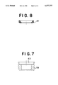
- FIG. 8 is a sectional view of an inventive seat shown in FIG. 6;
- FIG. 9 is a view in elevation, partly in section of a fifth ground joint coupling constructed in accordance with this invention.
- FIG. 10 is a partial view in section of a recess formed in the spud of the inventive ground joint coupling of FIG. 9;
- FIG. 11 is a sectional view of an inventive seat shown in FIG. 9;
- FIG. 12 is a view in elevation, partly in section of a sixth ground joint coupling constructed in accordance with this invention.
- FIG. 13 is a partial view in section of a recess formed in the spud of the inventive ground joint coupling of FIG. 12;
- FIG. 14 is a sectional view of an inventive seat shown in FIG. 12;
- FIG. 15 is a view in elevation, partly in section of a seventh ground joint coupling constructed in accordance with this invention showing a seat mounted on the outer surface of a stem;
- FIG. 16 is an exploded view in elevation and partial section of the stem and spud of the coupling shown in FIG. 15 showing the seat installed on the stem;
- FIG. 17 is a view in elevation, partly in section of an eighth and ninth ground joint coupling constructed in accordance with this invention.
- FIG. 18 is an exploded view in elevation and partial section of the stem and spud of the eighth coupling shown in FIG. 17 showing the seat installed on the stem;
- FIG. 19 is an exploded view in elevation and partial section of the stem and spud of the ninth coupling shown in FIG. 17, showing the seat installed on the stem.
- Ground joint coupling 11 for hoses 13 for transporting steam, high or low-pressure air, water, liquid petroleum gas, fluid petroleum products, chemicals, potable fluids, or almost any other type of fluid or gas.
- Ground joint coupling 11 comprises a stem 15, preferably of carbon steel, stainless steel, or malleable iron, having a ground joint head 17 formed at the first end portion 19 of stem 15, a spud 21, preferably of carbon steel, stainless steel, or malleable iron, a molded annular seat 23 positioned between the ground joint head 17 and spud 21, and connection and compression means 25 for connecting the stem 15 to the spud 21 and for compressing the seat 23 between the ground joint head 17 and the spud 21.
- a hose barb 27 is formed at the second end portion 29 of stem 15 which is inserted into hose 13.
- a first integral collar 33 is formed on stem 15 at the end of barb 27, and first collar 33 acts as a stop for the end of hose 13.
- a recess 35 is formed on the first end portion of spud 21 which receives seat 23.
- Seat 23 is polymeric based, and preferably elastomeric based, and may be provided with a filler.
- the amount of filler added to the polymer is in the range of 0% to about 80% by weight of the seat 23.
- the maximum useful filler content is about 40% by volume, and the corresponding weight percentage to this may vary from 20% to 80%, depending on the density of the filler.
- Polymers that may be used include polytetrafluoroethylene (PTFE), ultra high molecular weight polyethylene (UHMWPE), polyetheretherketone compounds (PEEK), polyphenylene sulphide compounds (PPS), fluoroplastic compounds, and acetal compounds.
- PTFE polytetrafluoroethylene
- UHMWPE ultra high molecular weight polyethylene
- PEEK polyetheretherketone compounds
- PPS polyphenylene sulphide compounds
- fluoroplastic compounds and acetal compounds.
- Filler that may be used includes glass, moly, carbon, bronze, graphite, calcium fluoride, polyphenolinesulfide (PPS), ceramics, silica-based minerals, carbon/graphite, stainless steel, and combinations thereof.
- the filler is in a powder form, except glass which preferably is in a fiber form or a bead form.
- a preferred seat 23 comprises polytetrafluoroethylene (PTFE), alone or with a filler.
- Filler includes glass, moly, carbon, bronze, graphite, calcium fluoride, polyphenolinesulfide (PPS), ceramics, silica-based minerals, carbon/graphite, stainless steel, and combinations thereof.
- Polytetrafluoroethylene (PTFE) is sold under such trademarks as TEFLON (DuPont), RULON (Furon), TURCITE (Shamban), and ALGOFLON (Ansimont).
- PTFE compounds are as follows:
- a seat 23 of polytetrafluoroethylene (PTFE), a non-thermo processable plastic, may be made by a cold compression process followed by a sintering at a temperature above 625° F.
- PTFE polytetrafluoroethylene
- powdered PTFE is blended with the filler, if a filler is being used. Then, the blend of PTFE and filler, or the powdered PTFE alone if no filler is being used, is mechanically pelletized using a pelletizer. The pelletized composition is then placed into a mold shaped to form the seat 23 and compression molded at room temperature using a high pressure press at 2000 to 10000 psi to form semi-finished seats. The semi-finished seats are sintered at a temperature above 685° F. for about one hour per inch of cross-section of the seat, deburred using a ceramic material in a vibratory tumbler, and machined if necessary.
- PTFE-based seats 23 may be made by slowly ram extruding a partially sintered powdered PTFE composition, which includes PTFE alone or with a filler, in short increments, at a pressure of about 7,000 psi to 10,000 psi and sintering at a temperature of about 685° F. to produce a polymer billet, in tube or rod form.
- the ram extruded billet is then cut into individual pieces to form semi-finished seats 23 and the semi-finished seats 23 are then machined into finished seats 23.
- a seat 23 of ultra-high molecular weight polyethylene (UHMWPE), a linear polyolefin thermoplastic, may be made by compression molding pelletized UHMWPE at 390° F.-410° F. and at a pressure of about 1/2 ton per square inch, followed by cooling while the seat 23 remains in the mold.
- UHMWPE based seats 23 may be made by a ram extrusion process, wherein powdered UHMWPE is extruded into billets at a pressure of about 1/2 ton per square inch and is sintered at about 390° F. The ram extruded billet is then cut into individual pieces to form semi-finished seats 23, and the semi-finished seats 23 are then machined into finished seats 23.
- UHMWPE is sold under such trademarks as CADCO (Cadilac Plastics), SOLIDUR (Solidur Plastics), and HOSTALEN GUR (Hoechst Celanese). Preferably, no fillers are used with UHMWPE.
- a seat 23 based on polyetheretherketone (PEEK), a crystalline aromatic thermal plastic may be made by injection molding a pelletized PEEK composition, which includes PEEK alone or with a filler, at 600° F.-750° F. at screw speeds in the region of 150-200 min. -1 . Then, the injection molded seat 23 may be machined into its final form. Also, the PEEK-based seat 13 may be made by compression molding a pelletized PEEK composition, which includes PEEK alone or with a filler, at about 750° F. and about 8,000 to 10,000 psi, and then machining the compression molded seat 23 into its final form.
- PEEK polyetheretherketone
- a PEEK-based seat 23 also may be made by ram extrusion, as described for the PTFE-based seats 23 and the UHMWPE seats 23, at a temperature of 660° F. and a pressure of 8,000 to 10,000 psi.
- Polyetheretherketone (PEEK) is sold under such trademarks as VICTREX (ICI), and ARLON (Greene Tweed). Filler such as glass, carbon, and PTFE may be used with polyetheretherketone (PEEK).
- a seat 23 based on poly phenylene sulfide (PPS), a linear aromatic thermoplastic may be made by injection molding a pelletized PPS composition, which includes PPS alone or with a filler, at 575° F.-675° F. at screw speeds of 150-200 min. -1 . Then, the injected molded seats may be machined into their final form. Also, a PPS-based seat 23 may be made by compression molding a pelletized PPS composition, which includes PPS alone or with a filler, at 575° F.-675° F. at 8,000-12,000 psi, allowing the seat 23 to cool while in the mold, deburring the seat 23 in a vibratory tumbler, and machining the seat 23 if necessary.
- PPS poly phenylene sulfide
- a PPS-based seat 23 also may be made by ram extrusion, as described for the PTFE-based seats 23 and the UHMWPE seats 23, at a temperature of 575° F.-675° F. and a pressure of 8,000 to 12,000 psi.
- Poly Phenylene Sulfide (PPS) is sold under such trademarks as RYTON (Phillips 66), FORTRON (Hoechst Celanese), SUFIL (Wilson-Fiberfill), and SUPEC (GE Plastics).
- Suitable filler includes glass, glass/graphite, carbon, and PTFE.
- a seat 23 based on poly chlorotrifluoroethylene (PCTFE), a crystalline thermoplastic may be made by injection molding a pelletized PCTFE composition, which includes PCTFE alone or with a filler, at a temperature around 425° F. and at screw speeds in the region of 150-200 min. -1 .
- PCTFE-based seats 23 also may be made by ram extrusion, as described for the PTFE-based seats 23 and the UHMWPE seats 23, at a temperature of about 425° F. and a pressure of 7,000 to 10,000 psi.
- the PCTFE composition is in a pelletized form rather than a powder form before being extruded.
- PCTFE Poly chlorotrifluoroethylene
- KEL-F (3M) and DAIFLON Daikin
- no fillers are used with poly chlorotrifluoroethylene (PCTFE), but glass fibers may be used.
- a seat 23 based on polyvinylidene fluoride may be made by injection molding a pelletized PVDF composition, which includes PVDF alone or with a filler, at a temperature around 338° F. and at a screw speed of 150-200 min. -1 .
- PVDF-based seats 23 also may be made by ram extrusion, as described for the PTFE-based seats 23 and the UHMWPE seats 23, at a temperature of about 338° F. and a pressure of 7,000 to 10,000 psi.
- PVDF is sold under the trademark KYNAR (Ansimont), and carbon may be used with PVDF as a filler.
- a seat 23 of poly perfluoro alkoxy may be made by injection molding a pelletized PFA composition, which includes PFA alone or with a filler, at a temperature around 580° F. and at screw speeds of 150-200 min. -1 PFA-based seats 23 also may be made by ram extrusion, as described for the PTFE-based seats 23 and the UHMWPE seats 23, at a temperature of about 580° F. and a pressure of 7,000 to 10,000 psi. However, preferably, the PFA composition is in a pelletized form rather than a powder form before being extruded. PFA is sold under the trademark TEFLON (DuPont).
- a PFA seat 23 may have glass in it as a filler.
- a seat 23 of poly ethylene chloro trifluoro ethylene may be made by injection molding pelletized PETFE at a temperature around 518° F. and at screw speeds of 150-200 min. -1 .
- PETFE-based seats 23 also may be made by ram extrusion, as described for the PTFE-based seats 23 and the UHMWPE seats 23, at a temperature of about 518° F. and a pressure of 9,000 to 12,000 psi.
- PETFE is sold under the trademark TEFZEL (DuPont).
- a seat 23 of acetal compounds may be made by injection molding pelletized acetal compounds at a temperature around 500° F. and screw speeds of 150-200 min. -1 .
- Acetal compound based seats 23 also may be made by ram extrusion, as described for the PTFE-based seats 23 and the UHMWPE seats 23, at a temperature of about 500° F. and a pressure of 10,000 psi.
- Acetal compounds are sold under such trademarks as DELRIN (DuPont) and CELCON (Celanese).
- annular flange 36 which partially protrudes over recess 35, abuts against a shoulder 37 formed in seat 23 after seat 23 is squeezed into recess 35, thereby holding seat 23 in recess 35.
- Connection and compression means 25 includes a nut 39, preferably of carbon steel, stainless steel, or malleable iron, having a shoulder 41 that engages a second collar 43 that is formed on and is integral with stem 15.
- Nut 39 has internal threads 45 that engage external threads 47 formed on spud 21.
- hose 13 is positioned on barb 27, and clamp 31 is tightened to secure hose 13 to barb 27.
- nut 39 Prior to hose 13 being positioned on barb 27, nut 39 is slid onto stem 15 so that shoulder 41 of nut 39 may engage second collar 43 of stem 15. Spud 21 is then screwed into nut 39 with internal threads 45 engaging external threads 47.
- Seat 23 which is pressed or squeezed into recess 35 of spud 21, provides a seal between stem 15 and spud 21 as ground joint head 17 presses into seat 23 when spud 21 is screwed into nut 39.
- FIGS. 4-19 show alternative embodiments of the invention.
- FIG. 4 shows a ground joint coupling that is substantially the same as the ground joint coupling 11 of FIG. 1, except female spud 21 is replaced by a male spud 51.
- Male spud 51 like spud 21 is provided with a recess 35 (FIG. 2) for holding the seat.
- FIG. 5 shows another inventive ground joint coupling 53.
- Coupling 53 is substantially the same as coupling 11, except female spud 21 is replaced by double spud 55.
- Double spud 55 like spud 21 is provided with a recess 35 (FIG. 2) for holding the seat.
- FIGS. 6-8 show another inventive ground joint coupling 57.
- a double spud 59 is used.
- a male spud or female spud may be used in place of double spud 59.
- Coupling 57 is substantially the same as coupling 53 of FIG. 5, except seat 61, unlike seat 23, is not provided with a shoulder, and recess 63, unlike recess 35, is not provided with a flange.
- Seat 61 is held firmly inside in recess 63 via a press fit since the outside diameter of the seat 61 is larger than the inside diameter of recess 63.
- FIGS. 9-11 show another ground joint coupling 65 of the invention.
- a female spud 67 is used.
- a male spud or double spud may also be used in this embodiment of the invention.
- Spud 67 is provided with a recess 69 (FIG. 10), which is shaped to receive an O-ring-type annular seat 71 (FIG. 11).
- Recess 69 has an annular flange 73 which aids in holding seat 71 in recess 69.
- FIGS. 12-14 show still another ground joint coupling 75 of the invention.
- a female spud 77 is used, but a male spud or double spud may also be used in this embodiment of the invention.
- Spud 77 is provided with a recess 79 (FIG. 13), which is shaped to receive a seat 81 having a tapered outer surface 83.
- FIGS. 15-16 illustrate another embodiment of the invention.
- coupling 85 has a chamfered surface 87 formed on the first end portion of spud 89 that is adapted to press against a seat 91 that is mounted on the first end portion 93 of stem 95.
- a ledge 97 is formed at the first end portion 93 of stem 95 which receives a first end portion 99 of seat 91.
- An annular channel 101 also is formed in the first end portion 93 of stem 95 which receives the second end portion 103 of seat 91.
- Seat 91 rests against the outer surface of first end portion 93 as seat 91 extends between its first end portion 99 resting on ledge 97 and its second end portion 103 positioned in channel 101.
- Seat 91 is pressed onto stem 95.
- FIGS. 17-19 two more alternative embodiments of the invention are illustrated.
- a seat 107 is shown, and more clearly shown in FIG. 18, having a first end portion 109 adapted to be pressed against a chamfered surface 111 of spud 113, and a ramp-shaped second end portion 115 that is adapted to be received in a similarly shaped recess 117 formed in the first end portion 119 of stem 121.
- Coupling 123 shown on the right-hand side of FIG. 17 has a seat 125, more clearly shown in FIG. 19, having a first end portion 127 adapted to be squeezed against chamfered surface 111 of spud 113, and a second end portion 131 having an outwardly extending annular shoulder 133, the second end portion 131 of seat 125 being received in a correspondingly shaped recess 135 formed in stem 137.
- FIGS. 12-19 a female spud is used for illustration purposes. However, a male spud or double spud may also be used in these embodiments of the invention.
- Seats 61, 71, 81, 91, 107, and 125 have the same composition as seat 23.
- the inventive coupling is an all-purpose hose coupling which may be used in conjunction with steam hose connections.
- the inventive coupling may also be used with hoses for transporting high or low-pressure air, water, liquid petroleum gas, fluid petroleum products, chemicals, potable fluids, and almost any other type of fluid or gas.
- the inventive coupling eliminates the waste involved with copper seats.
- the seat of the invention is recommended for use in temperatures up to 500° F., which is more than the maximum tube temperature limitation of steam hose (406° F. at 250 p.s.i.), and is recommended for temperatures down to -100° F.
- the copper seat Since sealing of a coupling using a copper seat is achieved by impact tightening, the copper seat is not field replaceable. Further, if a copper seat is dented, it is hard to seal the coupling using it even after impact tightening. However, unlike copper seat couplings, sealing of the inventive coupling is achieved by wrench tightening, and impact tightening is not necessary, although impact tightening may be done without sacrificing any benefits of the invention. Accordingly, the polymeric seat of the invention is field replaceable. Further, the inventive seat, if dented, is easily sealed even with wrench tightening.
- the inventive coupling offers many advantages over the standard copper seat coupling.
- the process of providing a spud with a seat of the invention involves only a few steps. Specifically, after the spud of the invention is formed (same steps as those in the process of making spuds with a copper seat), the spud is zinc plated, and the polymer seat is pushed with slight pressure into the internal recess formed on the first end portion of the spud.
- assembling a polymeric seat onto a spud in accordance with the invention requires fewer steps than assembling a copper seat onto a spud, fewer quality control steps are needed for assembling polymeric seat couplings that are needed for assembling copper seat couplings.
- assembling a polymeric seat of the invention onto a spud requires less handling of parts than that required for assembling a copper seat onto a spud.
- Shorter lead time is needed to assemble seats of the invention onto spuds than is needed to assemble copper seats onto spuds because assembling the inventive polymeric seat onto spuds, when compared to assembling copper onto spuds, requires fewer operational steps, less handling time, fewer quality control steps, and greater ease in scheduling due to fewer operations.
- extruded polymer/polymer-filler billets may be stock piled, if desired, for later processing into finished seats.
Abstract
A ground joint coupling for hoses comprises a stem, a ground joint head formed at a first end portion of the stem, a spud having a first end portion, a molded polymeric annular seat adapted to be positioned between the ground joint head of the stem and the first end portion of the spud, and a nut for connecting the stem to the spud and for compressing the seat between the ground joint head of the stem and the first end portion of the spud. The seat may be made of polytetrafluoroethylene, ultra high molecular weight polyethylene, polyetheretherketone compounds, polyphenylene sulfide compounds, fluoroplastic compounds, or acetal compounds, and the seat may include a filler, such as glass, moly, carbon, bronze, graphite, calcium fluoride, polyphenoline-sulfide, ceramics, silica-based minerals, or combinations thereof.
Description
This is a continuation of application Ser. No. 07/854,317 filed on Mar. 19, 1992 now abandoned.
1. Field of the Invention
The present invention relates to the field of ground joint couplings for hoses for transporting steam, high or low-pressure air, water, liquid petroleum gas, fluid petroleum products, chemicals, potable fluids, or almost any other type of fluid or gas, and more particularly concerns ground joint couplings having a polymeric seat for sealing the ground joint coupling.
2. Description of the Prior Art
Conventional ground joint couplings for hoses comprise a stem and a spud held together by a nut. Sealing the coupling between the stem and the spud is accomplished by pressing a ground joint head formed in one end portion of the stem into a copper seat positioned in a recess in an end portion of a spud.
With conventional ground joint couplings, the process of making the copper seat and the process of providing a spud having the copper seat are time consuming and wasteful.
A copper seat is made by cutting off or rolling off from a copper pipe a portion of appropriate length for the seat. This portion of copper pipe in the form of a ring is then annealed. The annealed ring is then manually placed in a recess formed in the end portion of the spud, where it is machined to the appropriate drawing dimensions. The spud, with the copper seat in place, is then zinc plated. The zinc plating is then polished off the copper seat.
Errors in these processes result in the copper seat and/or the spud with copper seat being scrapped or reworked.
Also, with the copper seat coupling, sealing requires impact tightening (e.g., tightening the coupling by impacting the lug of the nut manually with a hammer or the like). Accordingly, the copper seat is not field replaceable because the copper seat is very difficult to separate from the recess of the spud after impact tightening.
with the copper seat coupling, if the copper seat is dented during processing or handling, it is difficult to seal the coupling even after impact tightening.
It is an object of the invention to provide a ground joint coupling that does not require a copper seat to seal the coupling between its stem and its spud.
Another object of the invention is to provide a ground joint coupling that may be produced more efficiently and in less time than a copper seat ground joint coupling.
Another object of the invention is to provide a ground joint coupling having a polymeric seat that may be field replaceable and that provides required sealing by wrench tightening and that does not require impact tightening to obtain an effective seal.
FIG. 1 is a view in side elevation, partially in longitudinal section of a ground joint coupling constructed in accordance with this invention;
FIG. 2 is a partial view in section of a recess formed in the spud of the inventive ground joint coupling;
FIG. 3 is a view in elevation, partly in section of a seat constructed in accordance with the invention;
FIG. 4 is a view in elevation, partly in section of a second ground joint coupling constructed in accordance with this invention;
FIG. 5 is a view in elevation, partly in section of a third ground joint coupling constructed in accordance with this invention;
FIG. 6 is a view in elevation, partly in section of a fourth ground joint coupling constructed in accordance with this invention;
FIG. 7 is a partial view in section of a recess formed in the spud of the inventive ground joint coupling of FIG. 6;
FIG. 8 is a sectional view of an inventive seat shown in FIG. 6;
FIG. 9 is a view in elevation, partly in section of a fifth ground joint coupling constructed in accordance with this invention;
FIG. 10 is a partial view in section of a recess formed in the spud of the inventive ground joint coupling of FIG. 9;
FIG. 11 is a sectional view of an inventive seat shown in FIG. 9;
FIG. 12 is a view in elevation, partly in section of a sixth ground joint coupling constructed in accordance with this invention;
FIG. 13 is a partial view in section of a recess formed in the spud of the inventive ground joint coupling of FIG. 12;
FIG. 14 is a sectional view of an inventive seat shown in FIG. 12;
FIG. 15 is a view in elevation, partly in section of a seventh ground joint coupling constructed in accordance with this invention showing a seat mounted on the outer surface of a stem;
FIG. 16 is an exploded view in elevation and partial section of the stem and spud of the coupling shown in FIG. 15 showing the seat installed on the stem;
FIG. 17 is a view in elevation, partly in section of an eighth and ninth ground joint coupling constructed in accordance with this invention;
FIG. 18 is an exploded view in elevation and partial section of the stem and spud of the eighth coupling shown in FIG. 17 showing the seat installed on the stem; and
FIG. 19 is an exploded view in elevation and partial section of the stem and spud of the ninth coupling shown in FIG. 17, showing the seat installed on the stem.
Turning to the drawings, there is shown in FIG. 1 a ground joint coupling 11 for hoses 13 for transporting steam, high or low-pressure air, water, liquid petroleum gas, fluid petroleum products, chemicals, potable fluids, or almost any other type of fluid or gas. Ground joint coupling 11 comprises a stem 15, preferably of carbon steel, stainless steel, or malleable iron, having a ground joint head 17 formed at the first end portion 19 of stem 15, a spud 21, preferably of carbon steel, stainless steel, or malleable iron, a molded annular seat 23 positioned between the ground joint head 17 and spud 21, and connection and compression means 25 for connecting the stem 15 to the spud 21 and for compressing the seat 23 between the ground joint head 17 and the spud 21.
A hose barb 27 is formed at the second end portion 29 of stem 15 which is inserted into hose 13. A clamp 31, preferably of carbon steel, stainless steel, or malleable iron, clamps a portion of hose 13 against barb 27. A first integral collar 33 is formed on stem 15 at the end of barb 27, and first collar 33 acts as a stop for the end of hose 13.
As shown in FIG. 1, and more particularly in FIG. 2, a recess 35 is formed on the first end portion of spud 21 which receives seat 23.
Seat 23 is polymeric based, and preferably elastomeric based, and may be provided with a filler. The amount of filler added to the polymer is in the range of 0% to about 80% by weight of the seat 23. The maximum useful filler content is about 40% by volume, and the corresponding weight percentage to this may vary from 20% to 80%, depending on the density of the filler.
Polymers that may be used include polytetrafluoroethylene (PTFE), ultra high molecular weight polyethylene (UHMWPE), polyetheretherketone compounds (PEEK), polyphenylene sulphide compounds (PPS), fluoroplastic compounds, and acetal compounds.
Filler that may be used includes glass, moly, carbon, bronze, graphite, calcium fluoride, polyphenolinesulfide (PPS), ceramics, silica-based minerals, carbon/graphite, stainless steel, and combinations thereof. Preferably, the filler is in a powder form, except glass which preferably is in a fiber form or a bead form.
A preferred seat 23 comprises polytetrafluoroethylene (PTFE), alone or with a filler. Filler includes glass, moly, carbon, bronze, graphite, calcium fluoride, polyphenolinesulfide (PPS), ceramics, silica-based minerals, carbon/graphite, stainless steel, and combinations thereof. Polytetrafluoroethylene (PTFE) is sold under such trademarks as TEFLON (DuPont), RULON (Furon), TURCITE (Shamban), and ALGOFLON (Ansimont).
Illustrative examples of the PTFE compounds are as follows:
______________________________________ PTFE COMPOUNDS ______________________________________ 100% PTFE (VIRGIN) 75% PTFE, 25% GIASS 80% PTFE, 15% GLASS, 5% MOLY PTFE, PPS, CARBON, MOLY PTFE, PPS, GLASS 85% PTFE, 15%GLASS 75% PTFE, 25% GLASS (GREEN) 95% PTFE, 5% MOLY 40% PTFE, 55% BRONZE, 5% MOLY 85% PTFE, 15% GRAPHITE 80% PTFE, 20% CALCIUM FLUORIDE 76% PTFE, 22% PPS, 4% GRAPHITE 70% PTFE, 25% CARBON, 5% CERAMIC 98% PTFE, 2% CARBON 85% PTFE, 15% MINERAL-SILICA BASED 65% PTFE, 30% GLASS, 5% MOLY 90% PTFE, 5% GLASS, 5%GRAPHITE 85% PTFE, 15% CARBON/GRAPHITE 55% PTFE, 40% GLASS, 5% MOLY 20% PTFE, 80% STAINLESS STEEL 30% PTFE, 70% STAINLESS STEEL 40% PTFE, 60% BRONZE 60% PTFE, 40% BRONZE 60% PTFE, 40%GLASS 75% PTFE, 25% PPS (POLYPHENOLINESULFIDE) 55% PTFE, 40% BRONZE, 5% MOLY ______________________________________
All percentages are by percentage weight.
A seat 23 of polytetrafluoroethylene (PTFE), a non-thermo processable plastic, may be made by a cold compression process followed by a sintering at a temperature above 625° F.
Using a compression process, powdered PTFE is blended with the filler, if a filler is being used. Then, the blend of PTFE and filler, or the powdered PTFE alone if no filler is being used, is mechanically pelletized using a pelletizer. The pelletized composition is then placed into a mold shaped to form the seat 23 and compression molded at room temperature using a high pressure press at 2000 to 10000 psi to form semi-finished seats. The semi-finished seats are sintered at a temperature above 685° F. for about one hour per inch of cross-section of the seat, deburred using a ceramic material in a vibratory tumbler, and machined if necessary.
Also, PTFE-based seats 23 may be made by slowly ram extruding a partially sintered powdered PTFE composition, which includes PTFE alone or with a filler, in short increments, at a pressure of about 7,000 psi to 10,000 psi and sintering at a temperature of about 685° F. to produce a polymer billet, in tube or rod form. The ram extruded billet is then cut into individual pieces to form semi-finished seats 23 and the semi-finished seats 23 are then machined into finished seats 23.
Illustrative examples of other preferred compounds are as follows:
______________________________________
POLYETHYLENE COMPOUNDS
100% UHMWPE (Ultra-High Molecular Weight
Polyethylene)
POLYETHERETHERKETONE COMPOUNDS (PEEK)
100% PEEK (UNFILLED)
 80% PEEK, 20% GLASS
 70% PEEK, 30% GLASS
POLYPHENYLENE SULFIDE COMPOUNDS (PPS)
 60% PPS, 40% GLASS
 60% PPS, 40% GLASS/GRAPHITE
FLUOROPLASTIC COMPOUNDS
100% PVDF VIRGIN - KYNAR
 80% PVDF, 20% CARBON - KYNAR 320
100% PCTFE VIRGIN - KEL-F
 70% PFA, 30% GLASS - TEFLON
100% PETFE VIRGIN - TEFZEL
ACETAL COMPOUNDS (POM)
HOMOPOLYMER VIRGIN - DELRIN
COPOLYMER VIRGIN - CELCON
______________________________________
Again, all percentages are by percentage weight.
A seat 23 of ultra-high molecular weight polyethylene (UHMWPE), a linear polyolefin thermoplastic, may be made by compression molding pelletized UHMWPE at 390° F.-410° F. and at a pressure of about 1/2 ton per square inch, followed by cooling while the seat 23 remains in the mold. Also, UHMWPE based seats 23 may be made by a ram extrusion process, wherein powdered UHMWPE is extruded into billets at a pressure of about 1/2 ton per square inch and is sintered at about 390° F. The ram extruded billet is then cut into individual pieces to form semi-finished seats 23, and the semi-finished seats 23 are then machined into finished seats 23. UHMWPE is sold under such trademarks as CADCO (Cadilac Plastics), SOLIDUR (Solidur Plastics), and HOSTALEN GUR (Hoechst Celanese). Preferably, no fillers are used with UHMWPE.
A seat 23 based on polyetheretherketone (PEEK), a crystalline aromatic thermal plastic, may be made by injection molding a pelletized PEEK composition, which includes PEEK alone or with a filler, at 600° F.-750° F. at screw speeds in the region of 150-200 min.-1. Then, the injection molded seat 23 may be machined into its final form. Also, the PEEK-based seat 13 may be made by compression molding a pelletized PEEK composition, which includes PEEK alone or with a filler, at about 750° F. and about 8,000 to 10,000 psi, and then machining the compression molded seat 23 into its final form. A PEEK-based seat 23 also may be made by ram extrusion, as described for the PTFE-based seats 23 and the UHMWPE seats 23, at a temperature of 660° F. and a pressure of 8,000 to 10,000 psi. Polyetheretherketone (PEEK) is sold under such trademarks as VICTREX (ICI), and ARLON (Greene Tweed). Filler such as glass, carbon, and PTFE may be used with polyetheretherketone (PEEK).
A seat 23 based on poly phenylene sulfide (PPS), a linear aromatic thermoplastic, may be made by injection molding a pelletized PPS composition, which includes PPS alone or with a filler, at 575° F.-675° F. at screw speeds of 150-200 min.-1. Then, the injected molded seats may be machined into their final form. Also, a PPS-based seat 23 may be made by compression molding a pelletized PPS composition, which includes PPS alone or with a filler, at 575° F.-675° F. at 8,000-12,000 psi, allowing the seat 23 to cool while in the mold, deburring the seat 23 in a vibratory tumbler, and machining the seat 23 if necessary. A PPS-based seat 23 also may be made by ram extrusion, as described for the PTFE-based seats 23 and the UHMWPE seats 23, at a temperature of 575° F.-675° F. and a pressure of 8,000 to 12,000 psi. Poly Phenylene Sulfide (PPS) is sold under such trademarks as RYTON (Phillips 66), FORTRON (Hoechst Celanese), SUFIL (Wilson-Fiberfill), and SUPEC (GE Plastics). Suitable filler includes glass, glass/graphite, carbon, and PTFE.
A seat 23 based on poly chlorotrifluoroethylene (PCTFE), a crystalline thermoplastic, may be made by injection molding a pelletized PCTFE composition, which includes PCTFE alone or with a filler, at a temperature around 425° F. and at screw speeds in the region of 150-200 min.-1. PCTFE-based seats 23 also may be made by ram extrusion, as described for the PTFE-based seats 23 and the UHMWPE seats 23, at a temperature of about 425° F. and a pressure of 7,000 to 10,000 psi. However, preferably, the PCTFE composition is in a pelletized form rather than a powder form before being extruded. Poly chlorotrifluoroethylene (PCTFE) is sold under such trademarks as KEL-F (3M) and DAIFLON (Daikin). Usually, no fillers are used with poly chlorotrifluoroethylene (PCTFE), but glass fibers may be used.
A seat 23 based on polyvinylidene fluoride (PVDF) may be made by injection molding a pelletized PVDF composition, which includes PVDF alone or with a filler, at a temperature around 338° F. and at a screw speed of 150-200 min.-1. Also, PVDF-based seats 23 also may be made by ram extrusion, as described for the PTFE-based seats 23 and the UHMWPE seats 23, at a temperature of about 338° F. and a pressure of 7,000 to 10,000 psi. PVDF is sold under the trademark KYNAR (Ansimont), and carbon may be used with PVDF as a filler.
A seat 23 of poly perfluoro alkoxy (PFA) may be made by injection molding a pelletized PFA composition, which includes PFA alone or with a filler, at a temperature around 580° F. and at screw speeds of 150-200 min.-1 PFA-based seats 23 also may be made by ram extrusion, as described for the PTFE-based seats 23 and the UHMWPE seats 23, at a temperature of about 580° F. and a pressure of 7,000 to 10,000 psi. However, preferably, the PFA composition is in a pelletized form rather than a powder form before being extruded. PFA is sold under the trademark TEFLON (DuPont). A PFA seat 23 may have glass in it as a filler.
A seat 23 of poly ethylene chloro trifluoro ethylene (PETFE) may be made by injection molding pelletized PETFE at a temperature around 518° F. and at screw speeds of 150-200 min.-1. PETFE-based seats 23 also may be made by ram extrusion, as described for the PTFE-based seats 23 and the UHMWPE seats 23, at a temperature of about 518° F. and a pressure of 9,000 to 12,000 psi. PETFE is sold under the trademark TEFZEL (DuPont).
A seat 23 of acetal compounds may be made by injection molding pelletized acetal compounds at a temperature around 500° F. and screw speeds of 150-200 min.-1. Acetal compound based seats 23 also may be made by ram extrusion, as described for the PTFE-based seats 23 and the UHMWPE seats 23, at a temperature of about 500° F. and a pressure of 10,000 psi. Acetal compounds are sold under such trademarks as DELRIN (DuPont) and CELCON (Celanese).
Regarding the processes of compression molding, ram extrusion, and injection molding, reference is made to Concise Encyclopedia Of Polymer Science and Engineering (Jacqueline I. Kroschwitz, Executive Editor; John Wiley & Sons, Publisher), which is incorporated herein by reference.
Referring to FIGS. 2 and 3, an annular flange 36, which partially protrudes over recess 35, abuts against a shoulder 37 formed in seat 23 after seat 23 is squeezed into recess 35, thereby holding seat 23 in recess 35.
Connection and compression means 25 includes a nut 39, preferably of carbon steel, stainless steel, or malleable iron, having a shoulder 41 that engages a second collar 43 that is formed on and is integral with stem 15. Nut 39 has internal threads 45 that engage external threads 47 formed on spud 21.
To assemble coupling 11 onto hose 13, hose 13 is positioned on barb 27, and clamp 31 is tightened to secure hose 13 to barb 27.
Prior to hose 13 being positioned on barb 27, nut 39 is slid onto stem 15 so that shoulder 41 of nut 39 may engage second collar 43 of stem 15. Spud 21 is then screwed into nut 39 with internal threads 45 engaging external threads 47.
FIGS. 4-19 show alternative embodiments of the invention.
FIG. 4 shows a ground joint coupling that is substantially the same as the ground joint coupling 11 of FIG. 1, except female spud 21 is replaced by a male spud 51. Male spud 51, like spud 21 is provided with a recess 35 (FIG. 2) for holding the seat.
FIG. 5 shows another inventive ground joint coupling 53. Coupling 53 is substantially the same as coupling 11, except female spud 21 is replaced by double spud 55. Double spud 55, like spud 21 is provided with a recess 35 (FIG. 2) for holding the seat.
FIGS. 6-8 show another inventive ground joint coupling 57. In this embodiment of the invention, a double spud 59 is used. However, a male spud or female spud may be used in place of double spud 59. Coupling 57 is substantially the same as coupling 53 of FIG. 5, except seat 61, unlike seat 23, is not provided with a shoulder, and recess 63, unlike recess 35, is not provided with a flange. Seat 61 is held firmly inside in recess 63 via a press fit since the outside diameter of the seat 61 is larger than the inside diameter of recess 63.
FIGS. 9-11 show another ground joint coupling 65 of the invention. In this embodiment of the invention, a female spud 67 is used. However, a male spud or double spud may also be used in this embodiment of the invention. Spud 67 is provided with a recess 69 (FIG. 10), which is shaped to receive an O-ring-type annular seat 71 (FIG. 11). Recess 69 has an annular flange 73 which aids in holding seat 71 in recess 69.
FIGS. 12-14 show still another ground joint coupling 75 of the invention. In this embodiment of the invention, a female spud 77 is used, but a male spud or double spud may also be used in this embodiment of the invention. Spud 77 is provided with a recess 79 (FIG. 13), which is shaped to receive a seat 81 having a tapered outer surface 83.
FIGS. 15-16 illustrate another embodiment of the invention. Here, coupling 85 has a chamfered surface 87 formed on the first end portion of spud 89 that is adapted to press against a seat 91 that is mounted on the first end portion 93 of stem 95. As shown in FIGS. 15 and 16, a ledge 97 is formed at the first end portion 93 of stem 95 which receives a first end portion 99 of seat 91. An annular channel 101 also is formed in the first end portion 93 of stem 95 which receives the second end portion 103 of seat 91. Seat 91 rests against the outer surface of first end portion 93 as seat 91 extends between its first end portion 99 resting on ledge 97 and its second end portion 103 positioned in channel 101. Seat 91 is pressed onto stem 95.
Referring to FIGS. 17-19, two more alternative embodiments of the invention are illustrated. In the left-hand coupling 105 shown in FIG. 17, a seat 107 is shown, and more clearly shown in FIG. 18, having a first end portion 109 adapted to be pressed against a chamfered surface 111 of spud 113, and a ramp-shaped second end portion 115 that is adapted to be received in a similarly shaped recess 117 formed in the first end portion 119 of stem 121.
Coupling 123 shown on the right-hand side of FIG. 17 has a seat 125, more clearly shown in FIG. 19, having a first end portion 127 adapted to be squeezed against chamfered surface 111 of spud 113, and a second end portion 131 having an outwardly extending annular shoulder 133, the second end portion 131 of seat 125 being received in a correspondingly shaped recess 135 formed in stem 137.
In each of FIGS. 12-19, a female spud is used for illustration purposes. However, a male spud or double spud may also be used in these embodiments of the invention.
The inventive coupling is an all-purpose hose coupling which may be used in conjunction with steam hose connections. The inventive coupling may also be used with hoses for transporting high or low-pressure air, water, liquid petroleum gas, fluid petroleum products, chemicals, potable fluids, and almost any other type of fluid or gas.
The inventive coupling eliminates the waste involved with copper seats.
The seat of the invention is recommended for use in temperatures up to 500° F., which is more than the maximum tube temperature limitation of steam hose (406° F. at 250 p.s.i.), and is recommended for temperatures down to -100° F.
Since sealing of a coupling using a copper seat is achieved by impact tightening, the copper seat is not field replaceable. Further, if a copper seat is dented, it is hard to seal the coupling using it even after impact tightening. However, unlike copper seat couplings, sealing of the inventive coupling is achieved by wrench tightening, and impact tightening is not necessary, although impact tightening may be done without sacrificing any benefits of the invention. Accordingly, the polymeric seat of the invention is field replaceable. Further, the inventive seat, if dented, is easily sealed even with wrench tightening.
The inventive coupling offers many advantages over the standard copper seat coupling. For example, unlike the wasteful and time consuming process of providing spuds with a copper seat, the process of providing a spud with a seat of the invention involves only a few steps. Specifically, after the spud of the invention is formed (same steps as those in the process of making spuds with a copper seat), the spud is zinc plated, and the polymer seat is pushed with slight pressure into the internal recess formed on the first end portion of the spud. The need to anneal the copper ring, to roll it into the recess in the first end portion of the spud, to machine the copper seat to the appropriate dimension, and to polish zinc plating off the copper seat after the spud is zinc plated is eliminated.
Because assembling a polymeric seat onto a spud in accordance with the invention requires fewer steps than assembling a copper seat onto a spud, fewer quality control steps are needed for assembling polymeric seat couplings that are needed for assembling copper seat couplings.
Likewise, assembling a polymeric seat of the invention onto a spud requires less handling of parts than that required for assembling a copper seat onto a spud.
Shorter lead time is needed to assemble seats of the invention onto spuds than is needed to assemble copper seats onto spuds because assembling the inventive polymeric seat onto spuds, when compared to assembling copper onto spuds, requires fewer operational steps, less handling time, fewer quality control steps, and greater ease in scheduling due to fewer operations.
Due to the ease of manufacturing the components of the inventive coupling, a high inventory of product is not required to be kept.
Also, extruded polymer/polymer-filler billets may be stock piled, if desired, for later processing into finished seats.
Since fewer steps are required to assemble a polymeric seat onto a spud than are required to assemble a copper seat onto a spud, the chances of defects occurring are smaller. Accordingly, the amount of scrap produced and reworking required on assembled spuds is less with the process of assembling a polymeric seat of the invention onto a spud than it is with the process of assembling a copper seat onto a spud.
Claims (19)
1. A ground joint coupling (11) for steam hoses comprising
a stem (15),
a head (17) formed at a first end portion 19 of the stem (15) and having a head sealing surface comprising an exterior bevel flaring outwardly and rearwardly from the end of the end portion (19),
a spud (21) having a first end portion facing the first end portion (19) of the stem (15), the spud (21) being coaxial with the stem (15),
seat receiving means formed in the first end portion of the spud (21) for receiving a seat (23) having a seat outer surface profile,
said seat receiving means comprising an interior recess (35) having a surface profile conforming to said seat outer surface profile for preventing distortion of the outer surface profile of said polymeric seat and having a flange (36) at the end of the spud (21) with the flange extending inwardly for removably holding said seat in said interior recess,
a molded polymeric annular seat positioned in said interior recess (35) of the spud (21), said seat having a radially inwardly angular inner seat sealing surface which complements and forms a sealing line of contact with said head sealing surface,
connection and compression means (39) for connecting the stem (15) to the spud (21) by forcing said outside bevel of the stem against the inner seat sealing surface and providing a seal between the stem (15) and the spud (21), and
means for preventing direct contact between the stem (15) and the spud (21).
2. A ground joint coupling for steam hoses comprising
a stem (95),
a head formed on a first end portion (93) of the stem (95),
a spud (89) having a first end portion facing the first end portion (93) of the stem (95), the spud (89) being coaxial with the stem (95),
a chamfered annular surface (87) formed inside the first end portion (93) of the spud,
seat receiving means formed on the head of the stem (95) for receiving a seat (91),
said seat receiving means including an annular outside radial channel 101 formed in the head of the stem (95) transverse to the axis of the stem (95),
molded polymeric annular seat (91) positioned in said outside channel (101),
said seat (91) having a second end portion (103) fitting into said outside radial channel (101) for mounting said seat (91) onto the head of the stem (95),
said seat (91) having a first end portion (99) pressing against the chamfered surface (87) of the spud (89),
connection and compression means for connecting the stem (95) to the spud (89) and for pressing the head and the first end portion (99) of the seat (91) against the inside chamfered surface (87) of the spud (89) for providing a seal between the stem (95) and the spud (89)
said seat being formed from polytetrafluouroethylene, ultra high molecular weight polyethylene, polyetheretherketone compounds, polyphenylene sulfide compounds, fluoroplastic compounds, or acetal compounds,
said seat further including a filler,
the filler including glass, moly, carbon, bronze, graphite, calcium fluoride, polyphenolinesulfide, ceramics, silica-based minerals, PFA, stainless steel, or combinations thereof.
3. The ground joint coupling of claim 1, further including
a hose barb formed at the second end portion of the stem.
4. The ground joint coupling of claim 1, further including
the connection and compression means including a nut.
5. The ground joint coupling of claim 1, further including
the seat being formed from polytetrafluoroethylene.
6. The ground joint coupling of claim 5, the seat further including a filler.
7. The ground joint coupling of claim 6,
the filler including glass, moly, carbon, bronze, graphite, calcium fluoride, polyphenolinesulfide, ceramics, silica-based minerals, stainless steel or combinations thereof.
8. The ground joint coupling of claim 6, the filler being greater than 0% up to about 80% by weight of the seat.
9. The ground joint coupling of claim 6,
the filler comprising a maximum of about 40% by volume of the seat.
10. The ground joint coupling of claim 1,
the seat being made of ultra high molecular weight polyethylene, polyetheretherketone compounds, polyphenylene sulfide compounds, fluoroplastic compounds, or acetal compounds.
11. The ground joint coupling of claim 10, the seat further including a filler.
12. The ground joint coupling of claim 11,
the filler including glass, glass and graphite, carbon, or PFA.
13. The ground joint coupling of claim 11, the filler being greater than 0% up to about 80% by weight of the seat.
14. The ground joint coupling of claim 11,
the filler comprising a maximum of about 40% by volume of the seat.
15. A ground joint coupling for steam hoses comprising
a stem,
a head formed at a first end portion of the stem,
a spud having a first end portion facing the first end portion of the stem, the spud being coaxial with the stem,
seat receiving means (117) formed on the first end portion of the stem for receiving a seat (107),
said seat receiving means comprising an interior recess having a flange with an interior surface which partially defines the interior recess of the stem,
an interior annular shoulder formed on the first end portion of the stem and extending inwardly, and
a molded polymeric annular seat in said interior recess of the stem, and
connection and compression means for connecting the stem to the spud and for compressing the seat between the head of the stem and the shoulder on the first end portion of the spud for providing a seal between the stem and the spud,
a hose barb formed at the second end portion of the stem,
the connection and compression means including a nut,
said seat being formed from polytetrafluouroethylene, ultra high molecular weight polyethylene, polyetheretherketone compounds, polyphenylene sulfide compounds, fluoroplastic compounds, or acetal compounds,
said seat further including a filler,
the filler including glass, moly, carbon, bronze, graphite, calcium fluoride, polyphenolinesulfide, ceramics, silica-based minerals, PFA, stainless steel, or combinations thereof, and
the filler being greater than 0% up to about 80% by weight of the seat.
16. A molded polymeric annular seat for sealing between a ground joint head of a stem and a first end portion of a spud in a ground joint coupling, said seat comprising
an annular body,
an annular projecting portion extending from the annular body and forming a shoulder (37) adapted to contact a flange (36) of a recess (35) in a spud (21), and,
said seat comprising a polymer and a filler,
the polymer being polytetrafluouroethylene, ultra high molecular weight polyethylene, polyetheretherketone compounds, polyphenylene sulfide compounds, fluoroplastic compounds, or acetal compounds
the filler being glass, moly, carbon, bronze, graphite, calcium fluoride, polyphenoline-sulfide, ceramics, silica-based minerals, PFA, stainless steel, or combinations thereof,
the filler being greater than 0% up to about 80% by weight of the seat, and
the filler comprising a maximum of about 40% by volume of the seat.
17. The molded polymeric annular seat of claim 16, said annular body of said seat being triangular in cross section.
18. The molded polymeric annular seat of claim 16,
said seat having a first end portion (99) adapted to be seated in a ledge (97) formed in stem (95),
said seat having a second end portion (103) adapted to be seated in an outside channel (101).
19. The ground joint coupling recited in claim 1 wherein said seat sealing surface has a frustoconical surface profile.
Priority Applications (1)
| Application Number | Priority Date | Filing Date | Title |
|---|---|---|---|
| US08/335,558 US5577777A (en) | 1992-03-19 | 1994-11-07 | Ground joint coupling having a polymeric seat |
Applications Claiming Priority (2)
| Application Number | Priority Date | Filing Date | Title |
|---|---|---|---|
| US85431792A | 1992-03-19 | 1992-03-19 | |
| US08/335,558 US5577777A (en) | 1992-03-19 | 1994-11-07 | Ground joint coupling having a polymeric seat |
Related Parent Applications (1)
| Application Number | Title | Priority Date | Filing Date |
|---|---|---|---|
| US85431792A Continuation | 1992-03-19 | 1992-03-19 |
Publications (1)
| Publication Number | Publication Date |
|---|---|
| US5577777A true US5577777A (en) | 1996-11-26 |
Family
ID=25318349
Family Applications (1)
| Application Number | Title | Priority Date | Filing Date |
|---|---|---|---|
| US08/335,558 Expired - Lifetime US5577777A (en) | 1992-03-19 | 1994-11-07 | Ground joint coupling having a polymeric seat |
Country Status (1)
| Country | Link |
|---|---|
| US (1) | US5577777A (en) |
Cited By (10)
| Publication number | Priority date | Publication date | Assignee | Title |
|---|---|---|---|---|
| US6357755B1 (en) * | 1998-02-02 | 2002-03-19 | Maschinenfabrik Sulzer-Burckhardt Ag | Sealing elements for dry running piston compressors |
| US20060033286A1 (en) * | 2004-07-29 | 2006-02-16 | Coorstek, Inc. | Graphite loaded PTFE mechanical seals for rotating shafts |
| US20080272594A1 (en) * | 2005-10-19 | 2008-11-06 | Guy Malcolm Phillipps | Slip type pipe joint |
| US7464972B1 (en) * | 2005-04-01 | 2008-12-16 | Niemietz Roger D | Air evacuation attachment for fire hoses |
| CN100529007C (en) * | 2007-07-31 | 2009-08-19 | 徐州工程学院 | Nontoxic high-pressure resistant sealing material |
| AU2006303813B2 (en) * | 2005-10-19 | 2011-07-07 | Norma Pacific Pty Ltd | A slip type pipe joint |
| CN104964038A (en) * | 2015-07-06 | 2015-10-07 | 苏州捷宁模塑有限公司 | Fluoroplastic device used for mechanical seal |
| US20170261106A1 (en) * | 2014-11-28 | 2017-09-14 | Elringklinger Ag | Sealing element and method for producing a sealing element |
| US20180372252A1 (en) * | 2015-12-21 | 2018-12-27 | Rehau Ag + Co | Sliding sleeve connection |
| US11767935B2 (en) | 2015-12-21 | 2023-09-26 | Rehau Construction Llc | Connecting element and pipe connection comprising the same |
Citations (28)
| Publication number | Priority date | Publication date | Assignee | Title |
|---|---|---|---|---|
| US449293A (en) * | 1891-03-31 | Pipe-coupling | ||
| US489107A (en) * | 1893-01-03 | Carl august guido storz | ||
| US857956A (en) * | 1906-05-07 | 1907-06-25 | Mueller Mfg Co H | Pipe connection. |
| US954549A (en) * | 1907-02-19 | 1910-04-12 | Joseph C Hartwell | Pipe-coupling. |
| GB191004677A (en) * | 1910-02-24 | 1910-06-09 | William Edward Lake | Improvements in Pipe Couplings. |
| US1083350A (en) * | 1908-08-14 | 1914-01-06 | Westinghouse Automatic Air & Steam Coupler Company | Pipe-coupling gasket. |
| US1137113A (en) * | 1914-01-15 | 1915-04-27 | Everett J Bouchard | Pipe-coupling. |
| US2102072A (en) * | 1935-07-15 | 1937-12-14 | Frank J Hinderliter | Rotary tool joint |
| US2128473A (en) * | 1937-03-26 | 1938-08-30 | American Tap Bush Company | Tap construction |
| US2286263A (en) * | 1939-04-25 | 1942-06-16 | Ralph B Comins | Quick acting coupling |
| DE940025C (en) * | 1954-02-14 | 1956-03-08 | Pleiger Maschf Paul | Hose connection |
| CA618790A (en) * | 1961-04-25 | J. Kander Herbert | Gasket for sanitary fittings | |
| US3142499A (en) * | 1962-02-05 | 1964-07-28 | Pan American Petroleum Corp | Anchor and fluid seal for conduit liner |
| US3346263A (en) * | 1964-11-16 | 1967-10-10 | Harold B Newcomer | Air brake coupling components |
| US3964772A (en) * | 1969-04-24 | 1976-06-22 | Ideal Industries, Inc. | Connector for flexible metallic conduit and method |
| US4324423A (en) * | 1979-02-23 | 1982-04-13 | Isadore Pitesky | Tubular fitment |
| GB2114192A (en) * | 1982-02-03 | 1983-08-17 | Uss Eng & Consult | Improved swivel stem for delivering fluid to a rotary drill string |
| US4458926A (en) * | 1983-05-10 | 1984-07-10 | Williamson Nigel D L | Hydraulic hose adapter with O-ring seal |
| US4589688A (en) * | 1981-09-02 | 1986-05-20 | Fillpro Products, Inc. | Plumbing hookup kit |
| US4603888A (en) * | 1985-09-18 | 1986-08-05 | Dixon Valve & Coupling Company | End fitting |
| US4674775A (en) * | 1985-07-22 | 1987-06-23 | Osaka Gas Company Limited | Coupling for corrugated conduit |
| US4767135A (en) * | 1986-02-11 | 1988-08-30 | Hermann Holzmann | Screw-type conduit fitting |
| US4886303A (en) * | 1988-07-11 | 1989-12-12 | J. M. Huber Corporation | Coupling with improved elastomeric face seal |
| US4930791A (en) * | 1989-04-10 | 1990-06-05 | Fmc Corporation | Plastic bore seal |
| US4991876A (en) * | 1989-07-28 | 1991-02-12 | Euroflex, S.A. | Connector assembly for hot water heaters and other appliances |
| US5076313A (en) * | 1990-09-06 | 1991-12-31 | Bottum Jr Edward W | Fusible plug structure |
| US5131695A (en) * | 1991-03-13 | 1992-07-21 | Chatleff Controls, Inc. | Coupling with teflon seat |
| US5364135A (en) * | 1991-04-26 | 1994-11-15 | Anderson-Barrows Metal Corporation | End fitting for flexible conduit |
-
1994
- 1994-11-07 US US08/335,558 patent/US5577777A/en not_active Expired - Lifetime
Patent Citations (29)
| Publication number | Priority date | Publication date | Assignee | Title |
|---|---|---|---|---|
| CA618790A (en) * | 1961-04-25 | J. Kander Herbert | Gasket for sanitary fittings | |
| US489107A (en) * | 1893-01-03 | Carl august guido storz | ||
| US449293A (en) * | 1891-03-31 | Pipe-coupling | ||
| US857956A (en) * | 1906-05-07 | 1907-06-25 | Mueller Mfg Co H | Pipe connection. |
| US954549A (en) * | 1907-02-19 | 1910-04-12 | Joseph C Hartwell | Pipe-coupling. |
| US1083350A (en) * | 1908-08-14 | 1914-01-06 | Westinghouse Automatic Air & Steam Coupler Company | Pipe-coupling gasket. |
| GB191004677A (en) * | 1910-02-24 | 1910-06-09 | William Edward Lake | Improvements in Pipe Couplings. |
| US1137113A (en) * | 1914-01-15 | 1915-04-27 | Everett J Bouchard | Pipe-coupling. |
| US2102072A (en) * | 1935-07-15 | 1937-12-14 | Frank J Hinderliter | Rotary tool joint |
| US2128473A (en) * | 1937-03-26 | 1938-08-30 | American Tap Bush Company | Tap construction |
| US2286263A (en) * | 1939-04-25 | 1942-06-16 | Ralph B Comins | Quick acting coupling |
| DE940025C (en) * | 1954-02-14 | 1956-03-08 | Pleiger Maschf Paul | Hose connection |
| US3142499A (en) * | 1962-02-05 | 1964-07-28 | Pan American Petroleum Corp | Anchor and fluid seal for conduit liner |
| US3346263A (en) * | 1964-11-16 | 1967-10-10 | Harold B Newcomer | Air brake coupling components |
| US3964772A (en) * | 1969-04-24 | 1976-06-22 | Ideal Industries, Inc. | Connector for flexible metallic conduit and method |
| US4324423A (en) * | 1979-02-23 | 1982-04-13 | Isadore Pitesky | Tubular fitment |
| US4589688A (en) * | 1981-09-02 | 1986-05-20 | Fillpro Products, Inc. | Plumbing hookup kit |
| GB2114192A (en) * | 1982-02-03 | 1983-08-17 | Uss Eng & Consult | Improved swivel stem for delivering fluid to a rotary drill string |
| US4458926A (en) * | 1983-05-10 | 1984-07-10 | Williamson Nigel D L | Hydraulic hose adapter with O-ring seal |
| US4674775A (en) * | 1985-07-22 | 1987-06-23 | Osaka Gas Company Limited | Coupling for corrugated conduit |
| US4603888A (en) * | 1985-09-18 | 1986-08-05 | Dixon Valve & Coupling Company | End fitting |
| US4767135A (en) * | 1986-02-11 | 1988-08-30 | Hermann Holzmann | Screw-type conduit fitting |
| US4886303A (en) * | 1988-07-11 | 1989-12-12 | J. M. Huber Corporation | Coupling with improved elastomeric face seal |
| US4930791A (en) * | 1989-04-10 | 1990-06-05 | Fmc Corporation | Plastic bore seal |
| US4991876A (en) * | 1989-07-28 | 1991-02-12 | Euroflex, S.A. | Connector assembly for hot water heaters and other appliances |
| US5076313A (en) * | 1990-09-06 | 1991-12-31 | Bottum Jr Edward W | Fusible plug structure |
| US5131695A (en) * | 1991-03-13 | 1992-07-21 | Chatleff Controls, Inc. | Coupling with teflon seat |
| US5131695B1 (en) * | 1991-03-13 | 1994-01-18 | Chatleff Controls, Inc. | |
| US5364135A (en) * | 1991-04-26 | 1994-11-15 | Anderson-Barrows Metal Corporation | End fitting for flexible conduit |
Cited By (13)
| Publication number | Priority date | Publication date | Assignee | Title |
|---|---|---|---|---|
| US6357755B1 (en) * | 1998-02-02 | 2002-03-19 | Maschinenfabrik Sulzer-Burckhardt Ag | Sealing elements for dry running piston compressors |
| US20060033286A1 (en) * | 2004-07-29 | 2006-02-16 | Coorstek, Inc. | Graphite loaded PTFE mechanical seals for rotating shafts |
| US7464972B1 (en) * | 2005-04-01 | 2008-12-16 | Niemietz Roger D | Air evacuation attachment for fire hoses |
| US20080272594A1 (en) * | 2005-10-19 | 2008-11-06 | Guy Malcolm Phillipps | Slip type pipe joint |
| AU2006303813B2 (en) * | 2005-10-19 | 2011-07-07 | Norma Pacific Pty Ltd | A slip type pipe joint |
| CN100529007C (en) * | 2007-07-31 | 2009-08-19 | 徐州工程学院 | Nontoxic high-pressure resistant sealing material |
| US10774932B2 (en) | 2014-11-28 | 2020-09-15 | Elringklinger Ag | Sealing element and method for producing a sealing element |
| US20170261106A1 (en) * | 2014-11-28 | 2017-09-14 | Elringklinger Ag | Sealing element and method for producing a sealing element |
| US20210341059A1 (en) * | 2014-11-28 | 2021-11-04 | Elringklinger Ag | Sealing element and method for producing a sealing element |
| CN104964038A (en) * | 2015-07-06 | 2015-10-07 | 苏州捷宁模塑有限公司 | Fluoroplastic device used for mechanical seal |
| US20180372252A1 (en) * | 2015-12-21 | 2018-12-27 | Rehau Ag + Co | Sliding sleeve connection |
| US11060644B2 (en) * | 2015-12-21 | 2021-07-13 | REHAU Construction LLC. | Sliding sleeve connection |
| US11767935B2 (en) | 2015-12-21 | 2023-09-26 | Rehau Construction Llc | Connecting element and pipe connection comprising the same |
Similar Documents
| Publication | Publication Date | Title |
|---|---|---|
| US5577777A (en) | Ground joint coupling having a polymeric seat | |
| EP2141393B1 (en) | Valve manufacturing method, and valve | |
| US4711474A (en) | Pipe joint seal rings | |
| CN115723369A (en) | Seal and method for producing a seal | |
| EP2350222B1 (en) | Large diameter thermoplastic seal | |
| KR101083107B1 (en) | Boreable plain bearing material | |
| EP0169635B1 (en) | Method for producing a tube of thermoplastic resin having poor melt flowability and apparatus therefor | |
| US7846365B2 (en) | Method of manufacture of a nut and tail assembly | |
| US20170234470A1 (en) | Connective outlet fitting for liquid color dispensing | |
| DE3414008A1 (en) | CASSETTE SEAL | |
| KR101019364B1 (en) | Receiving opening of joint for working fluid and valve with the receiving opening | |
| US20110127771A1 (en) | Fittings for high pressure hydraulic couplings | |
| JP4017671B2 (en) | Low permeability fluid seal for flow control device | |
| CN104086993B (en) | A kind of graft crosslinking polyamide liner tubing preparation method and high-temperature resistant inner lining oil pick-up tube | |
| US20080061551A1 (en) | Coupling nuts, coupling assembly including a coupling nut, and method of forming a coupling nut | |
| US20090284004A1 (en) | Double containment system, fittings for fluid flow components and associated methods | |
| US4861076A (en) | Gasket for sanitary pipe fittings | |
| US6871880B1 (en) | Irrigation adaptor | |
| US3883256A (en) | Ball and socket joints which do not require servicing and have an outer jacket of a thermoplastic, and process for their manufacture | |
| EP0574563A1 (en) | A method for producing a packing arrangement for a hydraulically operated apparatus and a packing arrangement | |
| KR20100051679A (en) | Thermoplastic polymer bushings | |
| US3050084A (en) | Valve for controlling back pressure in plastic extruders | |
| CN116981868A (en) | Sealing ring | |
| US3738615A (en) | Interfacial surface generator | |
| CN204022720U (en) | A kind of high-temperature resistant inner lining oil pick-up tube |
Legal Events
| Date | Code | Title | Description |
|---|---|---|---|
| STCF | Information on status: patent grant |
Free format text: PATENTED CASE |
|
| FPAY | Fee payment |
Year of fee payment: 4 |
|
| FPAY | Fee payment |
Year of fee payment: 8 |
|
| FPAY | Fee payment |
Year of fee payment: 12 |