US5546979A - Device for draining fluid from a container - Google Patents
Device for draining fluid from a container Download PDFInfo
- Publication number
- US5546979A US5546979A US08/384,946 US38494695A US5546979A US 5546979 A US5546979 A US 5546979A US 38494695 A US38494695 A US 38494695A US 5546979 A US5546979 A US 5546979A
- Authority
- US
- United States
- Prior art keywords
- fluid
- fluid container
- container
- screw means
- threaded
- Prior art date
- Legal status (The legal status is an assumption and is not a legal conclusion. Google has not performed a legal analysis and makes no representation as to the accuracy of the status listed.)
- Expired - Lifetime
Links
Images

Classifications
-
- B—PERFORMING OPERATIONS; TRANSPORTING
- B25—HAND TOOLS; PORTABLE POWER-DRIVEN TOOLS; MANIPULATORS
- B25B—TOOLS OR BENCH DEVICES NOT OTHERWISE PROVIDED FOR, FOR FASTENING, CONNECTING, DISENGAGING OR HOLDING
- B25B27/00—Hand tools, specially adapted for fitting together or separating parts or objects whether or not involving some deformation, not otherwise provided for
- B25B27/0035—Hand tools, specially adapted for fitting together or separating parts or objects whether or not involving some deformation, not otherwise provided for for motor-vehicles
- B25B27/0042—Tools for removing or replacing filters or for draining oil; Tools for setting or loosening closure means for radiators, batteries, or the like
-
- B—PERFORMING OPERATIONS; TRANSPORTING
- B09—DISPOSAL OF SOLID WASTE; RECLAMATION OF CONTAMINATED SOIL
- B09B—DISPOSAL OF SOLID WASTE
- B09B3/00—Destroying solid waste or transforming solid waste into something useful or harmless
-
- F—MECHANICAL ENGINEERING; LIGHTING; HEATING; WEAPONS; BLASTING
- F01—MACHINES OR ENGINES IN GENERAL; ENGINE PLANTS IN GENERAL; STEAM ENGINES
- F01M—LUBRICATING OF MACHINES OR ENGINES IN GENERAL; LUBRICATING INTERNAL COMBUSTION ENGINES; CRANKCASE VENTILATING
- F01M11/00—Component parts, details or accessories, not provided for in, or of interest apart from, groups F01M1/00 - F01M9/00
- F01M11/04—Filling or draining lubricant of or from machines or engines
- F01M11/0408—Sump drainage devices, e.g. valves, plugs
-
- F—MECHANICAL ENGINEERING; LIGHTING; HEATING; WEAPONS; BLASTING
- F16—ENGINEERING ELEMENTS AND UNITS; GENERAL MEASURES FOR PRODUCING AND MAINTAINING EFFECTIVE FUNCTIONING OF MACHINES OR INSTALLATIONS; THERMAL INSULATION IN GENERAL
- F16L—PIPES; JOINTS OR FITTINGS FOR PIPES; SUPPORTS FOR PIPES, CABLES OR PROTECTIVE TUBING; MEANS FOR THERMAL INSULATION IN GENERAL
- F16L41/00—Branching pipes; Joining pipes to walls
- F16L41/04—Tapping pipe walls, i.e. making connections through the walls of pipes while they are carrying fluids; Fittings therefor
-
- F—MECHANICAL ENGINEERING; LIGHTING; HEATING; WEAPONS; BLASTING
- F16—ENGINEERING ELEMENTS AND UNITS; GENERAL MEASURES FOR PRODUCING AND MAINTAINING EFFECTIVE FUNCTIONING OF MACHINES OR INSTALLATIONS; THERMAL INSULATION IN GENERAL
- F16L—PIPES; JOINTS OR FITTINGS FOR PIPES; SUPPORTS FOR PIPES, CABLES OR PROTECTIVE TUBING; MEANS FOR THERMAL INSULATION IN GENERAL
- F16L41/00—Branching pipes; Joining pipes to walls
- F16L41/08—Joining pipes to walls or pipes, the joined pipe axis being perpendicular to the plane of the wall or to the axis of another pipe
- F16L41/16—Joining pipes to walls or pipes, the joined pipe axis being perpendicular to the plane of the wall or to the axis of another pipe the branch pipe comprising fluid cut-off means
-
- B—PERFORMING OPERATIONS; TRANSPORTING
- B09—DISPOSAL OF SOLID WASTE; RECLAMATION OF CONTAMINATED SOIL
- B09B—DISPOSAL OF SOLID WASTE
- B09B2101/00—Type of solid waste
- B09B2101/02—Gases or liquids enclosed in discarded articles, e.g. aerosol cans or cooling systems of refrigerators
-
- B—PERFORMING OPERATIONS; TRANSPORTING
- B09—DISPOSAL OF SOLID WASTE; RECLAMATION OF CONTAMINATED SOIL
- B09B—DISPOSAL OF SOLID WASTE
- B09B2101/00—Type of solid waste
- B09B2101/20—Filters, e.g. oil filters
-
- Y—GENERAL TAGGING OF NEW TECHNOLOGICAL DEVELOPMENTS; GENERAL TAGGING OF CROSS-SECTIONAL TECHNOLOGIES SPANNING OVER SEVERAL SECTIONS OF THE IPC; TECHNICAL SUBJECTS COVERED BY FORMER USPC CROSS-REFERENCE ART COLLECTIONS [XRACs] AND DIGESTS
- Y10—TECHNICAL SUBJECTS COVERED BY FORMER USPC
- Y10T—TECHNICAL SUBJECTS COVERED BY FORMER US CLASSIFICATION
- Y10T137/00—Fluid handling
- Y10T137/598—With repair, tapping, assembly, or disassembly means
- Y10T137/612—Tapping a pipe, keg, or apertured tank under pressure
- Y10T137/6123—With aperture forming means
-
- Y—GENERAL TAGGING OF NEW TECHNOLOGICAL DEVELOPMENTS; GENERAL TAGGING OF CROSS-SECTIONAL TECHNOLOGIES SPANNING OVER SEVERAL SECTIONS OF THE IPC; TECHNICAL SUBJECTS COVERED BY FORMER USPC CROSS-REFERENCE ART COLLECTIONS [XRACs] AND DIGESTS
- Y10—TECHNICAL SUBJECTS COVERED BY FORMER USPC
- Y10T—TECHNICAL SUBJECTS COVERED BY FORMER US CLASSIFICATION
- Y10T137/00—Fluid handling
- Y10T137/598—With repair, tapping, assembly, or disassembly means
- Y10T137/612—Tapping a pipe, keg, or apertured tank under pressure
- Y10T137/613—With valved closure or bung
- Y10T137/6137—Longitudinal movement of valve
-
- Y—GENERAL TAGGING OF NEW TECHNOLOGICAL DEVELOPMENTS; GENERAL TAGGING OF CROSS-SECTIONAL TECHNOLOGIES SPANNING OVER SEVERAL SECTIONS OF THE IPC; TECHNICAL SUBJECTS COVERED BY FORMER USPC CROSS-REFERENCE ART COLLECTIONS [XRACs] AND DIGESTS
- Y10—TECHNICAL SUBJECTS COVERED BY FORMER USPC
- Y10T—TECHNICAL SUBJECTS COVERED BY FORMER US CLASSIFICATION
- Y10T137/00—Fluid handling
- Y10T137/8593—Systems
- Y10T137/87917—Flow path with serial valves and/or closures
- Y10T137/87925—Separable flow path section, valve or closure in each
- Y10T137/87941—Each valve and/or closure operated by coupling motion
- Y10T137/87949—Linear motion of flow path sections operates both
- Y10T137/87957—Valves actuate each other
-
- Y—GENERAL TAGGING OF NEW TECHNOLOGICAL DEVELOPMENTS; GENERAL TAGGING OF CROSS-SECTIONAL TECHNOLOGIES SPANNING OVER SEVERAL SECTIONS OF THE IPC; TECHNICAL SUBJECTS COVERED BY FORMER USPC CROSS-REFERENCE ART COLLECTIONS [XRACs] AND DIGESTS
- Y10—TECHNICAL SUBJECTS COVERED BY FORMER USPC
- Y10T—TECHNICAL SUBJECTS COVERED BY FORMER US CLASSIFICATION
- Y10T408/00—Cutting by use of rotating axially moving tool
- Y10T408/89—Tool or Tool with support
- Y10T408/907—Tool or Tool with support including detailed shank
-
- Y—GENERAL TAGGING OF NEW TECHNOLOGICAL DEVELOPMENTS; GENERAL TAGGING OF CROSS-SECTIONAL TECHNOLOGIES SPANNING OVER SEVERAL SECTIONS OF THE IPC; TECHNICAL SUBJECTS COVERED BY FORMER USPC CROSS-REFERENCE ART COLLECTIONS [XRACs] AND DIGESTS
- Y10—TECHNICAL SUBJECTS COVERED BY FORMER USPC
- Y10T—TECHNICAL SUBJECTS COVERED BY FORMER US CLASSIFICATION
- Y10T408/00—Cutting by use of rotating axially moving tool
- Y10T408/89—Tool or Tool with support
- Y10T408/909—Having peripherally spaced cutting edges
Definitions
- This invention relates to the field of removing fluid from containers, and more particularly to a tool for insertion into the wall of a container with fluid, i.e. an oil filter, to permit the fluid to be evacuated therefrom, before the filter is removed from the motor or machinery, to avoid leakage of the fluid from the filter.
- fluid i.e. an oil filter
- Lubrication systems in machinery, aircraft and vehicles require that their lubricants, viz., oil, and oil filters be replaced periodically in order to maintain the good working order of the engine and machinery.
- their lubricants viz., oil, and oil filters be replaced periodically in order to maintain the good working order of the engine and machinery.
- many mechanics recommend a oil and filter change every 3,000 miles of travel to maintain maximum engine life.
- Professional truckers put thousands of miles on their trucks every week and wait many, many hours for oil changes over the course of a year.
- Replacing the oil in a motor vehicle typically involves placing a large oil drain basin under the oil pan, removing the drain plug, thereby allowing the oil to drain therein, and unscrewing the oil filter from the engine block. Due to the engine designs of most engines, it has been difficult to remove oil filters without spilling oil onto the frame of the vehicle, on the mechanics and/or the ground. This is not only messy, but is environmentally unsound. Since many oil changes are conducted when the oil is very hot, this also poses a safety hazard to mechanics.
- U.S. Pat. No. 4,177,529 to Sikula, Jr. discloses an oil filter draining wrench which has a cylindrical housing with a center punch for punching and draining oil from an oil filter.
- the filter wrench is hammered onto the filter.
- a rubber gasket at the open end of the cylindrical housing sealingly engages the outside of the oil filter, and prevents oil from leaking out around the punch.
- An oil drain outlet is used to drain the oil from the housing which collects it.
- U.S. Pat. Nos. 4,776,431 and 4,865,156 to Poling disclose oil change devices and methods which utilize punches and vacuum chambers.
- the vacuum chambers are attached by suction to the oil filter, and the punches are driven into the filter's sidewalls, penetrating the filter.
- the oil will thus be evacuated out of the filter, through the vacuum chamber, and out the evacuation tube.
- the Poling devices unduly rely on the vacuum seal thus established, and these devices would not be expected to operate reliably.
- U.S. Pat. No. 5,299,714 to Kilgore discloses what is said to be a self-sealing oil filter punch, which is driven into the metal housing of an oil filter, so the oil can be drained through the hollow center of the punch and out the oil filter.
- the sharp tip of the punch is pushed through the bottom of the oil filter, and the punch has a resilient washer for sealing the punch against the oil filter's housing.
- a spigot valve is located on the end of the Kilgore device to control the oil flow through the punch.
- the Kilgore oil filter punch lacks means to positively engage the oil filter punch in fluid tight contact with the oil filter's housing, and jarring of the punch would be expected to unseat the seal. Moreover, if the spigot valve handle is advertently turned at an inopportune time, oil will spill out of the filter.
- U.S. Pat. No. 1,248,251 to Breaux discloses a faucet which is bored into a barrel to gain access to its contents.
- the faucet has an auger at its tip, for drilling into the barrel, which transitions into a smooth, widening tapered shaft which is driven into the barrel to provide frictional sealing engagement with walls of the barrel.
- the Breaux device may be acceptable for wood barrels, it would not be expected to function in the case of metal container, such as thin, metal-walled oil filters.
- the invention provides a fluid container draining device which allows fluid to be removed from a fluid container in a controlled manner, said fluid container having walls defining a fluid filled interior region therebetween, said fluid container draining device comprising:
- a threaded screw means having a sharpened tip at a forward region, which screw means when turned will penetrate the wall of the fluid container and enter the fluid containing cavity of the fluid container, said screw means having an internal channel communicating between an opening at the forward end of the screw means and a rear region of the threaded screw means, said rear region being externally threaded;
- a fluid valve means positioned at the rear region of the screw means in fluid connection with the channel, said fluid valve means providing fluid flow control between the interior of the fluid container and the outside of the fluid container, said fluid valve means having an internally threaded front region which screws into the externally threaded rear region of the screw means, and an externally threaded rear region, onto which a fluid evacuation line is to be attached.
- the invention further provides a fluid container draining device which allows fluid to be removed from a fluid container in a controlled manner, said fluid container having walls defining a fluid filled interior region therebetween, said fluid container draining device comprising:
- a threaded screw means having a sharpened, drill tip at its forward region, an externally threaded rear region lying behind said sharpened drill tip, and an internal channel communicating between an opening at the forward region of the screw means and a rear region of the threaded screw means, which screw means will penetrate the wall of the fluid container and gain access to the fluid containing cavity of the fluid container;
- a fluid valve means positioned at the rear region of the screw means in fluid connection with the channel, said fluid valve means providing fluid flow control between the interior of the fluid container and the outside of the fluid container, said fluid valve means having an internally threaded front region which screws into the externally threaded rear region of the screw means, an externally threaded rear region, onto which a fluid evacuation line is attached, and a turning region used to drill the device into wall of the fluid container to drain the fluid contained therein.
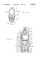
- FIG. 1 is a perspective side view of the device for draining fluid from a container.
- FIG. 2 is a cross-sectional view of the device through view lines 2--2 of FIG. 1.
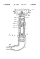
- FIG. 3 is a perspective view of the device being drilled into the wall of a fluid container.
- FIG. 4 is a partially exposed top view of the embodiment of FIG. 3, with the socket of a drill removed, and with its oil valve connected to a valve coupler and fluid transfer line, to evacuate fluid from the fluid container.
- the device 10 for drawing fluid from a fluid container 12 is shown.
- the container 12 is an oil filter, such as used for filtering the lubricants for motors and machinery.
- the device 10 of the invention can also be used to drain any number of containers, such as drums, cans, filters or pipes, of any number of fluids, e.g. lubricants, coolants, inks, and other chemicals.
- the device 10 includes a forwardly positioned threaded screw means portion 14.
- the threaded screw means portion 14 has a cutting and drilling tip 16, a fluid opening 18 located rearwardly of the cutting and drilling tip 16, and a male threaded screw portion 20 located rearwardly of the cutting and drilling tip 16.
- the fluid opening 18 leads to a screw means channel 22.
- a lip portion (“radially extending abutment surface") 24 is located behind the male threaded screw portion 20.
- a male threaded rear portion 26 is located rearward of the male threaded screw portion 20.
- the male threaded screw portion 20 is preferably conical in shape and has expanding "Acme-type" threads to work its way through the walls 28 of the container 12 and forms a tight seal.
- a valve portion 30 is positioned behind the screw means portion 14 and has a valve body 32 which has a female threaded front end 34, into which the male threaded rear portion 26 screws into liquid tightly.
- the lip portion 20 can comprise the leading front edge portion 33 of the valve body 32, or can be a separate piece, such as a washer 35.
- a longitudinal bore 36 is formed through the rear end 38 of the valve body 32, and terminates at a inner wall 40 located behind the female threaded front end 34 of the valve body 32.
- a passage channel 42 passes through the inner wall 40.
- the forward face 44 of the inner wall 40 closest to the front of the valve portion 30 has a seating surface 46.
- a valve head 48 is sized to seat on the seating surface 46.
- the valve head 48 has a valve shaft 50 extending rearwardly through the passage channel 42 and through the longitudinal bore 36, and is connected to a pushing portion 52, which normally sits near the rear end 38 of the valve body 32.
- the pushing portion 52 has a opening 54 formed therethrough to permit fluid to flow therethrough, and the pushing portion 52 is sized to slide in the longitudinal bore 36.
- a biasing coil spring 56 is placed in the longitudinal bore 36 with its front end 58 contacting a rear face 60 of the inner wall 40 and with its rear end 62 contacting the inner side 64 of the pushing portion 52. This biasing coil spring 56 will thus bias the valve head 48 into sealing contact with the seating surface 46, and thus prevents the passage of any fluid through the passage channel 42.
- an O-ring 66 is preferably placed on the valve head 48.
- a hex turning area 68 is located on the valve body 32, in front of a male threaded rear end 70 of the valve body. As best shown in FIG. 3, the device 10 is driven into the wall 28 of the container 12 by a drill 72 with a socket wrench 74 which fits over the rear end 70 and on the hex turning area 68.
- FIG. 4 shows the device 10 engaged on a container 12--here an oil filter, and with a valve actuating coupler 76 attached to it.
- the valve actuating coupler 76 When the valve actuating coupler 76 is screwed onto the male threaded rear end 70 of the valve body 32, it pushes the pushing portion 52 and thus unseats the valve head 48 from the seating surface 46, and thus open up the passage channel 42 for fluid flow.
- a vacuum line 78 is connected to the valve actuating coupler 76. When vacuum is applied, fluid "F” is thereby evacuated from the container 12, through the fluid opening 18, the screw means channel 22, the now open passage channel 42, the valve actuating coupler 74, and out the vacuum line 76.
- the valve activating coupler 76 is the subject of a U.S. patent filed contemporaneously by the same inventors, and entitled, "LEAKPROOF DUAL ACTION FLUID TRANSFER VALVE.”
- the coupler 76 with its vacuum line 78 are disconnected from the device 10.
- the container 12 is an oil filter
- it can be unscrewed with the device 10 still screwed in, or the device 10 can be removed prior to removing the oil filter 12.
- the valve head 48 reseats on the seating surface 46, to thereby block the passage channel 42, so no fluid escapes.
- a cap (not shown) can be screwed onto the male threaded rear end 70 of the valve body 32 while the device is being screwed into the fluid supply.
- the above described device 10 provides an easy, fast, and clean device to drain fluid from a fluid containing vessel, such as oil filters, before the oil filter is removed from the vehicle or machine.
- a fluid containing vessel such as oil filters
Abstract
Description
Claims (11)
Priority Applications (10)
| Application Number | Priority Date | Filing Date | Title |
|---|---|---|---|
| US08/384,946 US5546979A (en) | 1994-09-02 | 1995-02-07 | Device for draining fluid from a container |
| ES95943648T ES2197215T3 (en) | 1995-02-07 | 1995-12-01 | IMPROVED DEVICE FOR DRAINING FLUID FROM A CONTAINER. |
| EP19950943648 EP0864033B1 (en) | 1995-02-07 | 1995-12-01 | Improved device for draining fluid from a container |
| AT95943648T ATE234997T1 (en) | 1995-02-07 | 1995-12-01 | DEVICE FOR DISCHARGING LIQUID FROM A CONTAINER |
| BR9510668A BR9510668A (en) | 1995-02-07 | 1995-12-01 | Optimized device for draining fluid from a container |
| DE1995630010 DE69530010T2 (en) | 1995-02-07 | 1995-12-01 | DEVICE FOR DISCHARGING LIQUID FROM A CONTAINER |
| DK95943648T DK0864033T3 (en) | 1995-02-07 | 1995-12-01 | Improved device for emptying a container of liquid |
| CA 2238938 CA2238938A1 (en) | 1995-02-07 | 1995-12-01 | Improved device for draining fluid from a container |
| PCT/US1995/015684 WO1997021023A1 (en) | 1995-02-07 | 1995-12-01 | Improved device for draining fluid from a container |
| AU45069/96A AU706276B2 (en) | 1995-02-07 | 1995-12-01 | Improved device for draining fluid from a container |
Applications Claiming Priority (3)
| Application Number | Priority Date | Filing Date | Title |
|---|---|---|---|
| US08/300,402 US5558140A (en) | 1994-09-02 | 1994-09-02 | Device for draining fluid from a container |
| US08/384,946 US5546979A (en) | 1994-09-02 | 1995-02-07 | Device for draining fluid from a container |
| PCT/US1995/015684 WO1997021023A1 (en) | 1995-02-07 | 1995-12-01 | Improved device for draining fluid from a container |
Related Parent Applications (1)
| Application Number | Title | Priority Date | Filing Date |
|---|---|---|---|
| US08/300,402 Continuation-In-Part US5558140A (en) | 1994-09-02 | 1994-09-02 | Device for draining fluid from a container |
Publications (1)
| Publication Number | Publication Date |
|---|---|
| US5546979A true US5546979A (en) | 1996-08-20 |
Family
ID=27170708
Family Applications (1)
| Application Number | Title | Priority Date | Filing Date |
|---|---|---|---|
| US08/384,946 Expired - Lifetime US5546979A (en) | 1994-09-02 | 1995-02-07 | Device for draining fluid from a container |
Country Status (10)
| Country | Link |
|---|---|
| US (1) | US5546979A (en) |
| EP (1) | EP0864033B1 (en) |
| AT (1) | ATE234997T1 (en) |
| AU (1) | AU706276B2 (en) |
| BR (1) | BR9510668A (en) |
| CA (1) | CA2238938A1 (en) |
| DE (1) | DE69530010T2 (en) |
| DK (1) | DK0864033T3 (en) |
| ES (1) | ES2197215T3 (en) |
| WO (1) | WO1997021023A1 (en) |
Cited By (38)
| Publication number | Priority date | Publication date | Assignee | Title |
|---|---|---|---|---|
| DE29616266U1 (en) * | 1996-09-11 | 1996-11-21 | Lindner Anton | Device for removing liquids from a liquid container, in particular a tank tapping device |
| US5775390A (en) * | 1993-11-03 | 1998-07-07 | Mohn; Frank | Apparatus for extraction of a fluent material from a container |
| US5813246A (en) * | 1995-12-05 | 1998-09-29 | Samsung Electronics Co., Ltd. | Water dispenser for a refrigerator |
| US5896886A (en) * | 1998-08-06 | 1999-04-27 | Wendt; Daniel F. | Oil filter wrench |
| US5971207A (en) * | 1997-05-16 | 1999-10-26 | Pcf Group, Inc. | Nozzle apparatus and method for dispensing powder coating material |
| US6070762A (en) * | 1997-03-10 | 2000-06-06 | Angelika Weibhaar | Device for emptying closed containers, especially fuel filters |
| US6199578B1 (en) * | 1995-12-01 | 2001-03-13 | C.H. & I. Technologies, Inc. | Device for draining fluid from a container |
| US6234350B1 (en) * | 1998-05-14 | 2001-05-22 | Josef Dagn | Device for removing a liquid from a closed cavity |
| US6244311B1 (en) | 1994-12-29 | 2001-06-12 | Bemis Manufacturing Company | Method and apparatus for removing and disposing of body fluids |
| US6358232B1 (en) | 1994-12-29 | 2002-03-19 | Bemis Manufacturing Company | Method and apparatus for removing and disposing of body fluids |
| US6360795B1 (en) * | 1999-03-22 | 2002-03-26 | J. S. Staedtler Gmbh & Co. | Device and arrangement for filling an ink reservoir |
| US6368310B1 (en) | 1993-06-08 | 2002-04-09 | Bemis Manufacturing Company | Medical suction system |
| US6390241B1 (en) * | 2000-03-02 | 2002-05-21 | Siemens Automotive Corporation | Precision non-contamination oiler |
| US6443427B2 (en) * | 2000-01-11 | 2002-09-03 | COUPAL ANDRé | Low-profile low restriction drain valve |
| US6569320B1 (en) | 2000-06-02 | 2003-05-27 | K.J. Manufacturing Co. | Apparatus for changing an engine fuel filter |
| US6626877B2 (en) | 2000-03-28 | 2003-09-30 | Bemis Manufacturing Company | Medical suction apparatus and methods for draining same |
| US6655498B1 (en) * | 1999-09-29 | 2003-12-02 | Nitto Kohki Co., Ltd. | Pipe coupling and drain plug for engine oil change |
| US6672477B2 (en) | 2001-01-12 | 2004-01-06 | Bemis Manufacturing Company | Method and apparatus for disposing of bodily fluids from a container |
| US20040084109A1 (en) * | 2002-10-31 | 2004-05-06 | Eastman Kodak Company | Cup and probe assembly for use in a valve system for transferring a liquid between two sources |
| US20040144734A1 (en) * | 2002-11-12 | 2004-07-29 | Toyoda Boshoku Corporation | Fluid filter, drain mechanism thereof, draining jig used in fluid filter and draining method of fluid filter |
| US20050126965A1 (en) * | 2003-12-15 | 2005-06-16 | Meddock Leroy J. | Coaxial full-flow and bypass oil filter |
| US20060086922A1 (en) * | 2004-10-21 | 2006-04-27 | Jensen Daniel W | Valve having axial and radial passages |
| US20060226065A1 (en) * | 2003-12-15 | 2006-10-12 | Meddock Leroy J | Coaxial full-flow and bypass oil filter apparatus and method |
| US20060278569A1 (en) * | 2003-12-15 | 2006-12-14 | Meddock Leroy J | Coaxial full-flow and bypass oil filter apparatus and method |
| US20060278570A1 (en) * | 2003-12-15 | 2006-12-14 | Meddock Leroy J | Coaxial full-flow and bypass oil filter apparatus and method |
| WO2008087097A1 (en) * | 2007-01-17 | 2008-07-24 | Andreas Wimmer | Method for changing filters |
| US20080230493A1 (en) * | 2007-03-19 | 2008-09-25 | Nelson Keith A | Oil filter drain tool |
| US20090308464A1 (en) * | 2008-06-16 | 2009-12-17 | Matthew Simon Cesarz | Filter draining device |
| US7674248B2 (en) | 2000-03-28 | 2010-03-09 | Bemis Manufacturing Company | Medical suction apparatus and methods for draining same |
| US20100084026A1 (en) * | 2008-10-03 | 2010-04-08 | Bobby Knoll | Oil Filter Drain Tool |
| US20110225786A1 (en) * | 2010-03-22 | 2011-09-22 | Macey George H | Drainable oil filter and method for draining oil from an engine |
| WO2011131271A1 (en) * | 2010-04-21 | 2011-10-27 | Bayerische Motoren Werke Aktiengesellschaft | Oil-filter device |
| US20120048420A1 (en) * | 2010-08-31 | 2012-03-01 | Martin Gary A | Liquid container refilling system and method |
| US20120186690A1 (en) * | 2011-01-25 | 2012-07-26 | Thomas Broadway | Filter Drain Kit and Method |
| WO2016079258A1 (en) * | 2014-11-19 | 2016-05-26 | öHLINS RACING AB | Device for filling a shock absorber |
| US20170082246A1 (en) * | 2015-09-23 | 2017-03-23 | Koch Pipeline Company, L.P. | System and method for measuring pressure and removing fluid from behind a flange of pipeline |
| EP3444179A1 (en) * | 2017-08-16 | 2019-02-20 | B+Btec International Bv | Access device for a fluid tank |
| US11110397B2 (en) * | 2018-06-04 | 2021-09-07 | Pure Berkey, Llc | Device and method for water priming microporous-carbon water filters using negative pressure |
Families Citing this family (4)
| Publication number | Priority date | Publication date | Assignee | Title |
|---|---|---|---|---|
| NL1009132C2 (en) * | 1998-05-12 | 1999-11-15 | Poulus Van Santen | Drain means, drain plug, drain coupling and method for coupling a drain plug and a drain coupling. |
| FR2833299B1 (en) * | 2001-12-12 | 2006-07-07 | Robert Fergani | DRAIN DEVICE FOR VEHICLE AND DRAINING METHOD USING SUCH A DEVICE |
| FR2856106A1 (en) * | 2003-06-11 | 2004-12-17 | Hev Ventzislav Nitc | Engine oil draining device for cars oil filter, has rubber ring providing sealing between metallic surface of oil filter and longitudinal channel to avoid oil leakage during draining of oil, and quick coupler for pneumatic suction of oil |
| CA2488718C (en) * | 2004-11-30 | 2012-11-27 | Active Gear Co Of Canada Limited | Frost plug adapter assembly |
Citations (12)
| Publication number | Priority date | Publication date | Assignee | Title |
|---|---|---|---|---|
| US552408A (en) * | 1895-12-31 | George barnes | ||
| US1818122A (en) * | 1925-05-25 | 1931-08-11 | Standard Oil Co | Receptacle-evacuating apparatus |
| US2184263A (en) * | 1938-03-04 | 1939-12-19 | Adler Solomon | Receptacle tap |
| US3072138A (en) * | 1960-04-01 | 1963-01-08 | Dresser Ind | Explosive-actuated service t |
| US3509905A (en) * | 1967-11-15 | 1970-05-05 | John W Mullins | Line clamping self-tapping service valve |
| US4137930A (en) * | 1977-01-26 | 1979-02-06 | Scholle Corporation | Single operation normally closed coupling valve |
| US4177529A (en) * | 1978-08-18 | 1979-12-11 | Deere & Company | Filter wrench |
| US4269237A (en) * | 1977-12-07 | 1981-05-26 | Berger Juergen | Sump oil draining and collecting device |
| US4672932A (en) * | 1986-10-07 | 1987-06-16 | Encon Systems, Ltd. | Full-flow filter for internal combustion engine, adaptable for use with a by-pass filter |
| US4676281A (en) * | 1984-06-21 | 1987-06-30 | Runo Nord | Arrangement in removable liquid containers and a method of removing same |
| US4776431A (en) * | 1986-10-03 | 1988-10-11 | Poling Denzil C | Oil change device |
| US5299714A (en) * | 1993-05-21 | 1994-04-05 | Kilgore Gary H | Oil filter puncturing, draining, and socket extension device |
-
1995
- 1995-02-07 US US08/384,946 patent/US5546979A/en not_active Expired - Lifetime
- 1995-12-01 BR BR9510668A patent/BR9510668A/en not_active IP Right Cessation
- 1995-12-01 CA CA 2238938 patent/CA2238938A1/en not_active Abandoned
- 1995-12-01 WO PCT/US1995/015684 patent/WO1997021023A1/en active IP Right Grant
- 1995-12-01 DE DE1995630010 patent/DE69530010T2/en not_active Expired - Fee Related
- 1995-12-01 EP EP19950943648 patent/EP0864033B1/en not_active Expired - Lifetime
- 1995-12-01 DK DK95943648T patent/DK0864033T3/en active
- 1995-12-01 AT AT95943648T patent/ATE234997T1/en not_active IP Right Cessation
- 1995-12-01 ES ES95943648T patent/ES2197215T3/en not_active Expired - Lifetime
- 1995-12-01 AU AU45069/96A patent/AU706276B2/en not_active Ceased
Patent Citations (12)
| Publication number | Priority date | Publication date | Assignee | Title |
|---|---|---|---|---|
| US552408A (en) * | 1895-12-31 | George barnes | ||
| US1818122A (en) * | 1925-05-25 | 1931-08-11 | Standard Oil Co | Receptacle-evacuating apparatus |
| US2184263A (en) * | 1938-03-04 | 1939-12-19 | Adler Solomon | Receptacle tap |
| US3072138A (en) * | 1960-04-01 | 1963-01-08 | Dresser Ind | Explosive-actuated service t |
| US3509905A (en) * | 1967-11-15 | 1970-05-05 | John W Mullins | Line clamping self-tapping service valve |
| US4137930A (en) * | 1977-01-26 | 1979-02-06 | Scholle Corporation | Single operation normally closed coupling valve |
| US4269237A (en) * | 1977-12-07 | 1981-05-26 | Berger Juergen | Sump oil draining and collecting device |
| US4177529A (en) * | 1978-08-18 | 1979-12-11 | Deere & Company | Filter wrench |
| US4676281A (en) * | 1984-06-21 | 1987-06-30 | Runo Nord | Arrangement in removable liquid containers and a method of removing same |
| US4776431A (en) * | 1986-10-03 | 1988-10-11 | Poling Denzil C | Oil change device |
| US4672932A (en) * | 1986-10-07 | 1987-06-16 | Encon Systems, Ltd. | Full-flow filter for internal combustion engine, adaptable for use with a by-pass filter |
| US5299714A (en) * | 1993-05-21 | 1994-04-05 | Kilgore Gary H | Oil filter puncturing, draining, and socket extension device |
Cited By (56)
| Publication number | Priority date | Publication date | Assignee | Title |
|---|---|---|---|---|
| US6673055B2 (en) | 1993-06-08 | 2004-01-06 | Bemis Manufacturing Company | Medical suction system |
| US6368310B1 (en) | 1993-06-08 | 2002-04-09 | Bemis Manufacturing Company | Medical suction system |
| US5775390A (en) * | 1993-11-03 | 1998-07-07 | Mohn; Frank | Apparatus for extraction of a fluent material from a container |
| US6494869B1 (en) | 1994-12-29 | 2002-12-17 | Bemis Manufacturing Company | Method and apparatus for removing and disposing of body fluids |
| US6358232B1 (en) | 1994-12-29 | 2002-03-19 | Bemis Manufacturing Company | Method and apparatus for removing and disposing of body fluids |
| US6244311B1 (en) | 1994-12-29 | 2001-06-12 | Bemis Manufacturing Company | Method and apparatus for removing and disposing of body fluids |
| US6199578B1 (en) * | 1995-12-01 | 2001-03-13 | C.H. & I. Technologies, Inc. | Device for draining fluid from a container |
| US5813246A (en) * | 1995-12-05 | 1998-09-29 | Samsung Electronics Co., Ltd. | Water dispenser for a refrigerator |
| DE29616266U1 (en) * | 1996-09-11 | 1996-11-21 | Lindner Anton | Device for removing liquids from a liquid container, in particular a tank tapping device |
| US6070762A (en) * | 1997-03-10 | 2000-06-06 | Angelika Weibhaar | Device for emptying closed containers, especially fuel filters |
| US5971207A (en) * | 1997-05-16 | 1999-10-26 | Pcf Group, Inc. | Nozzle apparatus and method for dispensing powder coating material |
| US6234350B1 (en) * | 1998-05-14 | 2001-05-22 | Josef Dagn | Device for removing a liquid from a closed cavity |
| US5896886A (en) * | 1998-08-06 | 1999-04-27 | Wendt; Daniel F. | Oil filter wrench |
| US6360795B1 (en) * | 1999-03-22 | 2002-03-26 | J. S. Staedtler Gmbh & Co. | Device and arrangement for filling an ink reservoir |
| US6655498B1 (en) * | 1999-09-29 | 2003-12-02 | Nitto Kohki Co., Ltd. | Pipe coupling and drain plug for engine oil change |
| US6443427B2 (en) * | 2000-01-11 | 2002-09-03 | COUPAL ANDRé | Low-profile low restriction drain valve |
| US6474445B2 (en) | 2000-03-02 | 2002-11-05 | Siemens Automotive Corporation | Precision non-contamination oiler |
| US6390241B1 (en) * | 2000-03-02 | 2002-05-21 | Siemens Automotive Corporation | Precision non-contamination oiler |
| US6626877B2 (en) | 2000-03-28 | 2003-09-30 | Bemis Manufacturing Company | Medical suction apparatus and methods for draining same |
| US7674248B2 (en) | 2000-03-28 | 2010-03-09 | Bemis Manufacturing Company | Medical suction apparatus and methods for draining same |
| US6569320B1 (en) | 2000-06-02 | 2003-05-27 | K.J. Manufacturing Co. | Apparatus for changing an engine fuel filter |
| US6672477B2 (en) | 2001-01-12 | 2004-01-06 | Bemis Manufacturing Company | Method and apparatus for disposing of bodily fluids from a container |
| US20040084109A1 (en) * | 2002-10-31 | 2004-05-06 | Eastman Kodak Company | Cup and probe assembly for use in a valve system for transferring a liquid between two sources |
| US6854494B2 (en) * | 2002-10-31 | 2005-02-15 | Eastman Kodak Company | Cup and probe assembly for use in a valve system for transferring a liquid between two sources |
| US20040144734A1 (en) * | 2002-11-12 | 2004-07-29 | Toyoda Boshoku Corporation | Fluid filter, drain mechanism thereof, draining jig used in fluid filter and draining method of fluid filter |
| US7297282B2 (en) * | 2002-11-12 | 2007-11-20 | Toyoda Boshoku Corporation | Fluid filter, drain mechanism thereof, draining jig used in fluid filter and draining method of fluid filter |
| US20060278569A1 (en) * | 2003-12-15 | 2006-12-14 | Meddock Leroy J | Coaxial full-flow and bypass oil filter apparatus and method |
| US7704397B2 (en) | 2003-12-15 | 2010-04-27 | Filtran Llc | Coaxial full-flow and bypass oil filter having cap with blades |
| US7090773B2 (en) | 2003-12-15 | 2006-08-15 | Spx Corporation | Coaxial full-flow and bypass oil filter |
| US20060278570A1 (en) * | 2003-12-15 | 2006-12-14 | Meddock Leroy J | Coaxial full-flow and bypass oil filter apparatus and method |
| US20060226065A1 (en) * | 2003-12-15 | 2006-10-12 | Meddock Leroy J | Coaxial full-flow and bypass oil filter apparatus and method |
| US7704396B2 (en) | 2003-12-15 | 2010-04-27 | Filtran Llc | Coaxial full-flow and bypass oil filter with spring/gasket arrangement |
| US20050126965A1 (en) * | 2003-12-15 | 2005-06-16 | Meddock Leroy J. | Coaxial full-flow and bypass oil filter |
| US7134641B2 (en) * | 2004-10-21 | 2006-11-14 | International Engine Intellectual Property Company, Llc | Valve having axial and radial passages |
| US20060086922A1 (en) * | 2004-10-21 | 2006-04-27 | Jensen Daniel W | Valve having axial and radial passages |
| WO2008087097A1 (en) * | 2007-01-17 | 2008-07-24 | Andreas Wimmer | Method for changing filters |
| US20080230493A1 (en) * | 2007-03-19 | 2008-09-25 | Nelson Keith A | Oil filter drain tool |
| US7846330B2 (en) | 2007-03-19 | 2010-12-07 | Nelson Keith A | Oil filter drain tool |
| US20090308464A1 (en) * | 2008-06-16 | 2009-12-17 | Matthew Simon Cesarz | Filter draining device |
| US8127784B2 (en) * | 2008-06-16 | 2012-03-06 | Matthew Simon Cesarz | Filter draining device |
| US20100084026A1 (en) * | 2008-10-03 | 2010-04-08 | Bobby Knoll | Oil Filter Drain Tool |
| US8002002B2 (en) | 2008-10-03 | 2011-08-23 | Bobby Knoll | Oil filter drain tool |
| US20110225786A1 (en) * | 2010-03-22 | 2011-09-22 | Macey George H | Drainable oil filter and method for draining oil from an engine |
| US8522415B2 (en) * | 2010-03-22 | 2013-09-03 | George H. Macey | Drainable oil filter system and method for draining oil from an engine |
| WO2011131271A1 (en) * | 2010-04-21 | 2011-10-27 | Bayerische Motoren Werke Aktiengesellschaft | Oil-filter device |
| US8940165B2 (en) | 2010-04-21 | 2015-01-27 | Bayerische Motoren Werke Aktiengesellschaft | Oil-filter device |
| US20120048420A1 (en) * | 2010-08-31 | 2012-03-01 | Martin Gary A | Liquid container refilling system and method |
| US8708006B2 (en) * | 2010-08-31 | 2014-04-29 | Gary A. Martin | Liquid container refilling system and method |
| US20120186690A1 (en) * | 2011-01-25 | 2012-07-26 | Thomas Broadway | Filter Drain Kit and Method |
| WO2016079258A1 (en) * | 2014-11-19 | 2016-05-26 | öHLINS RACING AB | Device for filling a shock absorber |
| US20170082246A1 (en) * | 2015-09-23 | 2017-03-23 | Koch Pipeline Company, L.P. | System and method for measuring pressure and removing fluid from behind a flange of pipeline |
| US10036511B2 (en) * | 2015-09-23 | 2018-07-31 | KPL South Texas, LLC | System and method for measuring pressure and removing fluid from behind a flange of pipeline |
| EP3444179A1 (en) * | 2017-08-16 | 2019-02-20 | B+Btec International Bv | Access device for a fluid tank |
| DE102017007700A1 (en) * | 2017-08-16 | 2019-02-21 | B+Btec International Bv | Access device for a fluid tank |
| US10661321B2 (en) | 2017-08-16 | 2020-05-26 | B+Btec International Bv | Access device for a fluid tank |
| US11110397B2 (en) * | 2018-06-04 | 2021-09-07 | Pure Berkey, Llc | Device and method for water priming microporous-carbon water filters using negative pressure |
Also Published As
| Publication number | Publication date |
|---|---|
| DE69530010D1 (en) | 2003-04-24 |
| BR9510668A (en) | 1999-05-04 |
| EP0864033B1 (en) | 2003-03-19 |
| ATE234997T1 (en) | 2003-04-15 |
| EP0864033A1 (en) | 1998-09-16 |
| DE69530010T2 (en) | 2003-12-18 |
| DK0864033T3 (en) | 2003-07-07 |
| WO1997021023A1 (en) | 1997-06-12 |
| CA2238938A1 (en) | 1997-06-12 |
| AU4506996A (en) | 1997-06-27 |
| ES2197215T3 (en) | 2004-01-01 |
| EP0864033A4 (en) | 1999-03-03 |
| AU706276B2 (en) | 1999-06-10 |
Similar Documents
| Publication | Publication Date | Title |
|---|---|---|
| US5546979A (en) | Device for draining fluid from a container | |
| US5558140A (en) | Device for draining fluid from a container | |
| US5704383A (en) | Tool and method for removing fluid from container | |
| US8002002B2 (en) | Oil filter drain tool | |
| US4177529A (en) | Filter wrench | |
| US6199578B1 (en) | Device for draining fluid from a container | |
| US5327862A (en) | Multi-port filter mounting adapter and fitting mounted to same for expediting removal of oil from internal combustion engine associated therewith and method for accomplishing same | |
| US7357225B2 (en) | Two part oil or fluid drain plug with magnet | |
| US4976233A (en) | Quick connect coupling adapters for facilitating simple and high speed oil change in an internal combustion engine | |
| US4951723A (en) | Motorcycle engine oil drain plug | |
| US7984661B2 (en) | Grease sampling kit, grease sampling devices made from the kit, and related methods | |
| US5579815A (en) | Drain valve assembly | |
| US20160069513A1 (en) | Oil Filter Drain Tool | |
| US4940209A (en) | Levered fluid drain valve | |
| US5403168A (en) | Double acting pump having inlet and outlet poppet valves | |
| US5411115A (en) | Oil drain plug | |
| US4815566A (en) | Drain valve and system | |
| US5299714A (en) | Oil filter puncturing, draining, and socket extension device | |
| US5530988A (en) | Device for clearing pipes or other lines with pressurized gas | |
| US8651134B1 (en) | Tool for oil filter drainage | |
| US6056874A (en) | Piercing filter oil containment boot | |
| US5407177A (en) | Oil valve devices for removing used oil from drain pans of vehicles | |
| US5546986A (en) | Leakproof dual action fluid transfer valve | |
| US5390823A (en) | Oil filter hand punch and drain tool | |
| US20070068734A1 (en) | Williams Link, II, a system, method and apparatus for pollution-free removal of fluids from mechanical reservoirs |
Legal Events
| Date | Code | Title | Description |
|---|---|---|---|
| AS | Assignment |
Owner name: CLARK TECHNOLOGY SYSTEMS, INC., CALIFORNIA Free format text: ASSIGNMENT OF ASSIGNORS INTEREST;ASSIGNORS:CLARK, JAMES E. II;SANTER, POUL VAN;REEL/FRAME:007937/0348;SIGNING DATES FROM 19950206 TO 19960320 |
|
| STCF | Information on status: patent grant |
Free format text: PATENTED CASE |
|
| FEPP | Fee payment procedure |
Free format text: PAYOR NUMBER ASSIGNED (ORIGINAL EVENT CODE: ASPN); ENTITY STATUS OF PATENT OWNER: SMALL ENTITY |
|
| AS | Assignment |
Owner name: C. H. & I. TECHNOLOGIES, INC., CALIFORNIA Free format text: CHANGE OF NAME;ASSIGNOR:CLARK TECHNOLOGY SYSTEMS, INC.;REEL/FRAME:008392/0149 Effective date: 19960515 |
|
| FEPP | Fee payment procedure |
Free format text: PAYOR NUMBER ASSIGNED (ORIGINAL EVENT CODE: ASPN); ENTITY STATUS OF PATENT OWNER: SMALL ENTITY Free format text: PAYER NUMBER DE-ASSIGNED (ORIGINAL EVENT CODE: RMPN); ENTITY STATUS OF PATENT OWNER: SMALL ENTITY |
|
| FPAY | Fee payment |
Year of fee payment: 4 |
|
| FPAY | Fee payment |
Year of fee payment: 8 |
|
| REMI | Maintenance fee reminder mailed | ||
| FPAY | Fee payment |
Year of fee payment: 12 |
|
| SULP | Surcharge for late payment |
Year of fee payment: 11 |