US5535371A - Portable computer with automatic adaption to different device types on a standard port - Google Patents
Portable computer with automatic adaption to different device types on a standard port Download PDFInfo
- Publication number
- US5535371A US5535371A US08/264,226 US26422694A US5535371A US 5535371 A US5535371 A US 5535371A US 26422694 A US26422694 A US 26422694A US 5535371 A US5535371 A US 5535371A
- Authority
- US
- United States
- Prior art keywords
- connector
- externally accessible
- cable
- output device
- data
- Prior art date
- Legal status (The legal status is an assumption and is not a legal conclusion. Google has not performed a legal analysis and makes no representation as to the accuracy of the status listed.)
- Expired - Lifetime
Links
Images


Classifications
-
- G—PHYSICS
- G06—COMPUTING; CALCULATING OR COUNTING
- G06F—ELECTRIC DIGITAL DATA PROCESSING
- G06F13/00—Interconnection of, or transfer of information or other signals between, memories, input/output devices or central processing units
- G06F13/38—Information transfer, e.g. on bus
- G06F13/382—Information transfer, e.g. on bus using universal interface adapter
- G06F13/385—Information transfer, e.g. on bus using universal interface adapter for adaptation of a particular data processing system to different peripheral devices
-
- G—PHYSICS
- G06—COMPUTING; CALCULATING OR COUNTING
- G06F—ELECTRIC DIGITAL DATA PROCESSING
- G06F2213/00—Indexing scheme relating to interconnection of, or transfer of information or other signals between, memories, input/output devices or central processing units
- G06F2213/0004—Parallel ports, e.g. centronics
Definitions
- the present invention relates to personal computers, and to methods for using them.
- Portable personal computers were introduced in the early 1980s, and proved to be very useful and popular. As this market has developed, it has become increasingly clear that users strongly desire systems to have small volume, small weight, physical durability, and long battery-powered lifetime. Thus, small portable computers (“laptop” computers) have proven extremely popular during the late 1980s. Users continue to demand more features, longer time between recharges, and lower weight and volume. This combination of demands is difficult to meet. In about 1990, another smaller generation of portable computers (“notebook” computers) began to appear, and further generations are now starting to appear or being discussed. This continuing shrinkage of form factors will only exacerbate the difficulty of the above tradeoffs.
- Portable computers are inherently more susceptible than desktop computers to accident, loss, and theft. Thus, if critical work is being done on a portable computer, backup is even more of a necessity than with a desktop computer.
- each external connector takes up precious square inches of surface area.
- each external connector is a point of vulnerability to electrostatic-discharge-induced component failure.
- each external connector is a possible point of entry for dirt and moisture.
- the possible power required by all connectors must be considered.
- a standard part of the ISA architecture is a parallel port which has a fairly standard definition.
- the pinout of this port, in the standard DB-25 connector, is shown in (e.g.) Dowden, Inside The EISA Computer (1990), which is hereby incorporated by reference.
- the standard use of the parallel port is to output quantities of data to a printer, and get back status signals from the printer.
- a parallel port can be used for fully bidirectional data transfer. See generally Greenberg, "Adapting the parallel port for bidirectional communication,” Microsoft Systems Journal, Vol.5 No.5 (Sept. 1990), at 107ff, which is hereby incorporated by reference.
- a disk drive An essential part of any computer is some sort of mass storage, which is normally a disk drive.
- a disk drive is made of several rotating platters, each coated with a magnetic medium like that used in magnetic recording tape.
- Tape heads (each a solenoid with a gap which is positioned close to the magnetic medium) are moved over the rotating platters, and the magnetic field at the tape head is sensed or driven to read or write data to specific locations on the rotating platter.
- this signal processing is usually performed in a disk drive controller on the motherboard, which is separate from the disk drive and is connected to it by a cable.
- this cable carries analog signals and low-level control signals. See generally, e.g., Rosch, "Boost the basics: upgrade your floppy disk drive," PC Sources, vol. 2 no. 4 (April 1991), at 230ff, which is hereby incorporated by reference; Martin, “Floppy Disk Controllers Feature Some Important Extras," Computer Design vol. 25 no. 15 (Aug. 15, 1986), at 22ff, which is hereby incorporated by reference; Young, “Constant-density recording comes alive with new chips," Electronic Design, Nov. 13, 1986, at 141ff, which is hereby incorporated by reference; and Bursky, "Floppy-disk controller puts it all on one chip,” Electronic Design, Sep. 4, 1986, at pp. 69ff, which is hereby incorporated by reference.
- Some personal computers have had the capability for addition of an external floppy disk drive (or tape drive or hard disk drive). This was normally accomplished by providing external control electronics for the external drive, or by bringing out the analog lines from the drive controller to an external connector.
- a computer system normally includes a number of complex hardware components (chips and subsystems).
- the various hardware elements (chips and subsystems) will each have their own internal procedures (reset procedures) to regain a stable and known state.
- reset procedures internal procedures
- the CPU performs various important overhead tasks 2 under software control. This phase of operation is generally referred to as "POST" (Power-On-Self-Test).
- a "bootstrap" program is run, to permit the CPU to begin execution of other software.
- the bootstrap program launches the CPU on execution of the primary operating system software; 3 the primary operating system can then be used by the user to launch an application program, either manually or automatically.
- BIOS basic input/output system
- BIOS software is normally packaged in a read-only-memory, together with the POST and boot software. (Thus, the term "BIOS" is often used more broadly, to refer to this whole collection of basic system routines in ROM or EPROM.)
- the application software will normally interface to an operating system (such as DOS, DOS+Windows, OS/2, UNIX of various flavors, or UNIX plus X-windows).
- the operating system is a background software program 9 which provides an application programming interface (API) for use by the application software.
- API application programming interface
- Some computer systems have previously used a feature table, stored in nonvolatile memory, to describe various characteristics of the machine.
- the IBM AT BIOS uses such a feature table (stored in battery-backed CMOS memory).
- This feature table in expanded form, has also been used in the IBM PS/2 systems and has been utilized in the system BIOS of all IBM AT- and PS/1-compatible personal computers.
- This table is in the form of a bit map where each bit refers to specific hardware implementations employed by the designers of the machine.
- this feature table is restricted to merely listing certain hardware features in the machine, such as the number of DMA controllers, and does not provide an interface to these features. Furthermore, the elements of the list are fixed.
- the present invention provides a portable computer system with a standard printer port, which can be used, in completely standard fashion, for connection to any standard printer, and with any standard operating system and application software.
- this printer port can also be used, at the user's option, not only for connection to a printer, but also for connection to a non-printer accessory. This is not the normal use of this standard port, but the disclosed innovations permit the computer to automatically detect use of such non-printer accessories on the printer port, and permit the computer to automatically interface to them.
- the pins of the parallel port connector are not only connected to the pins of the port controller (as is normal), but are also connected to the lines which run between the disk drive controller and the internal floppy drive.
- Hardware multiplexing is preferably used to avoid contention between the parallel port control logic and the floppy drive control logic.
- the present invention provides a portable computer system wherein the printer port can be used, at the user's option, not only for connection to a printer, but also for connection to an external tape backup, or to an external floppy disk drive.
- the present application discloses a portable computer system wherein the startup routines in the system software can rapidly accommodate the docking or undocking of the computer from an external peripheral (such as a floppy disk drive).
- the innovative system like older systems, contains configuration tables, in nonvolatile memory, which specify many configuration parameters, including disk drive parameters. Whenever the computer is booted tip, the startup software will check the configuration table against the actual configuration. If the external drive has been removed or reconnected since the tables were last updated, they will be found to be inaccurate at the next boot operation. When this occurs, the disclosed system does not update the tables from scratch; instead, it accesses additional nonvolatile storage, and retrieves or saves data which indicates the correct type for the external drive when present.
- the disclosed system automatically remaps the logical drive designators when the external drive is present.
- DOS computers many software packages expect or require installation from the A: drive.
- software can rapidly be installed from an external 51/4" floppy drive.
- the external floppy drive is the A: drive
- the internal drive is the B: drive; but when the laptop is booted in a standalone configuration, the internal drive will be the A: drive.
- the reversal of the logical drive assignments is a further feature which helps to achieve rapid loading of software.
- some software programs demand to be installed from the A: drive, and the disclosed innovative system permits the external drive to be the A: drive whenever it is hooked up.
- the presently preferred embodiment provides a portable computer system wherein the startup routines in the system software can rapidly accommodate the docking or undocking of the computer from an external peripheral (such as a floppy disk drive).
- an external peripheral such as a floppy disk drive.
- This sample system like older systems, contains configuration tables, in nonvolatile memory, which specify many configuration parameters, including disk drive parameters. Whenever the computer is booted up, the startup software will check the configuration table against the actual configuration. If the external drive has been removed or reconnected since the tables were last updated, they will be found to be inaccurate at the next boot operation. When this occurs, the disclosed system does not update the tables from scratch; instead, it accesses additional nonvolatile storage, and retrieves or saves data which indicates the correct type for the external drive when present.
- the disclosed system automatically remaps the logical drive designators when the external drive is present.
- DOS computers many software packages expect or require installation from the A: drive.
- software can rapidly be installed from an external 51/4" floppy drive.
- the external floppy drive is the A: drive
- the internal drive is the B: drive; but when the laptop is booted in a standalone configuration, the internal drive will be the A: drive.
- the reversal of the logical drive assignments is a further feature which helps to achieve rapid loading of software.
- some software programs demand to be installed from the A: drive, and the disclosed innovative system permits the external drive to be the A: drive whenever it is hooked up.
- a standard part of the ISA architecture is a parallel port which has a fairly standard definition. This port is most commonly used for connection of a printer, and hence is often referred to as the "printer port.”
- the pinout of this port, in the standard DB-25 connector, is shown (for example) in Dowden, Inside The EISA Computer (1990), which is hereby incorporated by reference.
- the standard use of the parallel port is to output quantities of data to a printer, and get back status signals from the printer.
- a parallel port can also be used for fully bidirectional data transfer. See, e.g., Greenberg, "Adapting the parallel port for bidirectional communication," Microsoft Systems Journal Vol.5 No.5 (Sept. 1990), at 107ff, which is hereby incorporated by reference.
- FIG. 1A shows the notebook computer of the presently preferred embodiment docked to a printer.
- FIG. 1B shows the notebook computer of the presently preferred embodiment docked to an external floppy disk drive.
- FIG. 1C shows the notebook computer of the presently preferred embodiment docked to an external tape backup drive.
- FIG. 2A shows the pinout of the standard DB-25 parallel port connector in the standard ISA architecture. These pin assignments are valid, in the presently preferred embodiment, when the DB-25 parallel port connector is being used for printer interface according to the standard ISA architecture (as in FIG. 1A), rather than for interface to an external floppy drive (as in FIG. 1B) or tape drive (as in FIG. 1C).
- FIG. 2B shows the pin assignments used, according to the present invention, when the DB-25 parallel port connector is being used for interface to an external floppy drive (as in FIG. 1B) or tape drive (as in FIG. 1C).
- FIG. 2C illustrates connection between the DB-25 parallel port connector and an external connector configured for and attached to a non-printer external input/output device (floppy drive or tape drive).
- FIGS. 3A-3E show the detailed structure of the preferred hardware embodiment, and FIG. 4 shows the physical appearance of the notebook computer of the presently preferred embodiment.
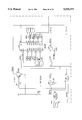
- FIGS. 5A-5C are three interrelated circuit diagrams showing how the floppy disk controller is connected to the internal floppy drive cable and to the printer port.
- FIG. 5A is shown on nine sheets labeled 5A-1, 5A-2, 5A-3, 5A-4, 5A-5, 5A-6, 5A-7, 5A-8 and 5A-9 and collectively referenced herein as FIG. 5A.
- FIG. 5B is shown on five sheets labeled 5B-1, 5B-2, 5B-3, 5B-4, and 5B-5 and collectively referenced herein as FIG. 5B.
- FIG. 5C is shown on eight sheets labeled 5C-1, 5C-2, 5C-3, 5C-4, 5C-5, 5C-6, 5C-7, and 5C-8 and collectively referenced herein as FIG. 5C.
- the presently preferred embodiment has been implemented on several different computer systems.
- the primary disclosed embodiment relates to the Dell 320N computer. This is a notebook computer, with an external closed size of about 8.5 ⁇ 11 ⁇ 2 inches.
- FIG. 4 shows a perspective view of the notebook computer 100, of the presently preferred embodiment, in the open position.
- This computer is a notebook computer, which includes a compact keyboard and screen in a rugged plastic case with a battery power supply. Visible elements include case 802, cover 804, hinges 806, display screen 810, keyboard 820, floppy disk drive 830, and dust cover 803 (which covers the receptacle for the rechargeable battery pack).
- This computer in the presently preferred embodiment, is a Dell 320NTM notebook computer, containing an Intel 386SX processor running at 20 MHz. (Hardware details and options of this computer, in the presently preferred embodiment, are extensively described in readily available Dell product literature, which is hereby incorporated by reference.) However, this model is merely one example of the hardware environments in which the inventions have been demonstrated to work.
- FIGS. 3A-3E show the detailed structure of the preferred hardware embodiment.
- the presently preferred embodiment has been implemented on several different computer systems.
- the primary disclosed embodiment relates to the Dell 320N computer. This is a notebook computer, with an external closed size of about 8.5 ⁇ 11 ⁇ 2 inches.
- FIG. 4 shows a perspective view of the notebook computer of the presently preferred embodiment in the open position.
- Visible elements include case 802, cover 804, hinges 806, display screen 810, keyboard 820, floppy disk drive 830, and dust cover 803 (which covers the receptacle for the rechargeable battery pack).
- the microprocessor 300 is an Intel 386SX processor running at 20 MHz. (Hardware details and options of this computer, in the presently preferred embodiment, are extensively described in readily available Dell product literature, which is hereby incorporated by reference.) However, this model is merely one example of the hardware environments in which the inventions have been demonstrated to work.
- an HT21 chip 310 is used to provide a variety of peripheral support functions to the main microprocessor. These include bus management, memory management, interrupt control, and DMA control. Serial port management and keyboard interface, and other I/O management functions, are provided by a VTI 82C186 combination chip 350. Of course, other implementations of support logic and glue logic can be used if desired, within this well-known architecture.
- FIGS. 3A-3E show the detailed structure of the preferred hardware embodiment.
- This computer is a notebook computer, which includes a compact keyboard and screen in a rugged plastic case with a battery power supply.
- FIG. 3A gives an overview of the principal electronic components of hardware architecture.
- Microprocessor 300 in the presently preferred embodiment, is a 386SX processor running at a 20 MHz clock rate. This microprocessor accesses bus 311, and memory 312, through controller 310.
- Bus and memory controller 310 in the presently preferred embodiment, is an HT21 chip from Headland Technologies. This chip provides a variety of peripheral support functions to the main microprocessor, including bus management, memory management, interrupt control, and DMA control.
- Bus 311 in the presently preferred embodiment, is an ISA bus.
- Memory 312 in the presently preferred embodiment, is DRAM, as discussed below.
- Video controller 330 is, in the presently preferred embodiment, a VGA chip, and is connected to additional components as shown in FIG. 3C below. This is implemented as a WD 90C20 VGA controller chip, in the presently preferred embodiment; but of course other components can optionally be used instead.
- Power Management Controller 320 is a microcontroller, in the presently preferred embodiment, and is connected to additional components as shown in FIG. 3D below.
- Hard disk drive 340 in the presently preferred embodiment, is a ruggedized 21/2" IDE drive, such as the Conners Peripherals 242 40 MB 2.5" hard disk. (Other sizes are also available.)
- Combination I/O Controller 350 is connected to additional components as shown in FIG. 3E below.
- FIG. 3B shows additional details of the connections of microprocessor 300 and bus controller 310.
- the microprocessor 300 is connected in parallel with a socket for an optional numeric co-processor 302 (e.g. a 387SX chip).
- Bus controller 310 receives two oscillator inputs.
- a 40 MHz crystal-controlled oscillator 319 provides a signal which is divided down to provide the clock for microprocessor 300.
- a 32 MHz crystal-controlled oscillator 318 provides a signal which is divided down to provide the clock for bus 311.
- the standard component of memory 312 is one megabyte of DRAMs, 8 bits wide. Sockets are provided for optional expansion memory 314 (1M ⁇ 8 or 2M ⁇ 8), and for optional expansion memory 316 (2M ⁇ 8). Both of these optional expansion memories are connected in parallel with memory 312 (except for slightly different address line connections).
- Flash EEPROM 360 provides a rewritable boot memory. (The operation of this memory is described in detail in commonly owned application 707,121, filed May 29, 1991, entitled “Computer System with Restorable Basic Firmware” (DC-200), which is hereby incorporated by reference.) When the flash memory 360 must be programmed, DC-DC converter 362 generates a 12-Volt programming voltage from the 5-Volt supply.
- the hardware system of the presently preferred embodiment uses only three circuit boards for all components other than the power supply.
- the components shown in FIGS. 3B and 3E are included on a common circuit board.
- FIGS. 3C and 3D show components which are on an I/O (bottom) circuit board 321 or inside the screen housing 333.
- FIG. 3C shows additional details of the connections of the video controller 330.
- a 14.318 MHz crystal-controlled oscillator 331 provides a reference frequency to video controller 330 and to bus controller 310.
- the video controller provides video output to inverter 334 and LCD display panel 336. (This is a Sharp VGA flat panel display, in the presently preferred embodiment, but of course other displays can be substituted.)
- a connection is also provided, in the presently preferred embodiment, for an external CRT monitor 332, which, if connected, can also be supplied with video signals from video controller 330.
- FIG. 3D shows additional details of the connections of the power management microcontroller 320.
- this is a National Semiconductor COP888CF series microcontroller, which is connected to receive various inputs for power-monitoring.
- An ASIC 322 provides interface logic, including sequential logic, for interfacing the microcontroller 320 to the system bus 311.
- An 8 MHz crystal-controlled oscillator 323 provides a clock signal to microcontroller 320 and interface chip 322.
- An SRAM 324 (which may be 8K ⁇ 8 or 32K ⁇ 8) is also accessed through the interface chip 322. This provides local memory which the microcontroller 320 can use.
- FIG. 3E shows additional details of the connections of the combination I/O controller 350.
- This chip receives clock inputs from an 18.432 MHz crystal-controlled oscillator 351B, and from a 32 KHz crystal-controlled oscillator 351A.
- This chip in the presently preferred embodiment, is a VTI 106; but of course a variety of other combination I/O management chips are available from Headland, Chips & Technologies, and other vendors, and other such chips can optionally be designed in.
- I/O controller 350 is connected to receive input from mouse port 386.
- I/O controller 350 is also connected to receive input from built-in keyboard 380, or from an external keyboard when one is plugged into external keyboard port 384.
- I/O controller 350 is also connected to communicate with an internal modem 354, if one is installed.
- I/O controller 350 is also connected to communicate, through RS232 interface 352, with a serial port connector (not shown).
- I/O controller 350 is also connected to communicate, through multiplexer 374, with printer (parallel) port 390.
- multiplexer 374 also, in the presently preferred embodiment, permits the floppy disk controller 372 to send and receive floppy disk interface signals over the parallel port connector 390. This novel feature permits an external floppy drive to be connected to the printer port connector 390.
- Floppy disk controller 372 interfaces to bus 311, and receives a clock signal from 24 MHz oscillator 371.
- Floppy disk controller 372 is a standard controller for a 31/2" floppy disk drive 370, which, in the presently preferred embodiment, is an Epson 3.5" floppy disk drive unit.
- the computer 100 also contains a conventional power supply circuitry (not shown), with connections for banks of rechargeable batteries. (Additional details of the power supply circuitry and battery connections are shown in application DC-172, referenced above, and hereby again incorporated by reference.)
- FIG. 1A schematically shows a sample embodiment, in which the computer 100 is docked to a lightweight portable printer 110, which is a Diconix in the presently preferred embodiment; but of course any other standard Centronics-interface printer can be used instead.
- FIG. 2A shows the (standard) signal assignments which are used in this case.
- FIG. 2B shows the nonstandard signal assignments which are used in this case.
- FIG. 2C by connecting a pair of pins together, an external multi-pin connector having connected said pins can indicate non-printer connection to the multi-pin connector upon the chassis.
- the chassis, and circuitry therein, can reconfigure the output signals shown in FIG. 2B from those shown in FIG. 2A whenever the common-connected pins of an external connector is coupled to the chassis connector, as shown in FIG. 2C.
- two different non-printer peripherals can be connected to the printer port. However, both of these non-printer peripherals use the same interface.
- the floppy disk drive 120 shown in FIG. 1B, contains only a power supply (connectable to a standard 120V wall socket), a standard off-the shelf floppy disk drive, and a 150 ⁇ resistor from pin 34 to RDY. In the presently preferred embodiment, this is a 1.2M Mitsubishi 504C drive; but of course any other standard 31/2" or 51/4" floppy drive can be used instead.
- a small floppy drive can be used without an independent power supply, and can rob all necessary power through the interface cable. This is expected to be an advantageous embodiment, but this is not yet part of the presently preferred embodiment.
- the backup tape drive 130 shown in FIG. 1C, contains only a power supply (connectable to a standard 120V wall socket), a standard off-the shelf floppy disk drive, and a 470 ⁇ pull-up resistor for presence detect.
- this is a 40M drive from Colorado Memory Systems, which uses DC2000 tape cartridges; but any other tape drive which accepts a standard floppy-disk interface can be used instead.
- the presently preferred embodiment uses hardware to detect the presence of a non-printer peripheral, and uses a combination of hardware and software techniques to reconfigure the port to accommodate printer or non-printer peripherals.
- FIGS. 5A-5C show the circuit implementation which is used, in the presently preferred embodiment, to detect the presence of a non-printer peripheral.
- a 10 ⁇ resistor R16 is inserted between pin 24 and ground. (Normally, pin 24 is simply grounded, without any such interposed resistor.) This means that this pin can be pulled high, if an attached accessory provides a sufficiently strong pull-up.
- the external disk drive 120 and the external tape drive 130 both include a pull-up on this line.
- FIGS. 5A-5C also shows the hardware components to route the appropriate printer or floppy-controller signals to printer port 390.
- the normal printer port lines F/P(1)-F/P(17) are connected to the appropriate lines of combination I/O chip 350 (shown in this FIG. 3E). These correspond to the signal functions shown in FIG. 2A.
- Buffer U36 is turned on IF an external floppy 120 (or tape 130) is attached: in this case the buffer U36 drives 8 pins straight to the port with floppy-control signals.
- Bipolar transistor Q1 on PTRVCC kills the VCC supply to chips U36 and U23, to prevent power consumption by these ALS chips unless a storage module is plugged in.
- the code portions set forth below provide the most relevant portions of the code used, but of course these code portions are used in combination with large additional portions of code.
- the software structure given below is used in combination with PhoenixTM BIOS code; but several vendors (such as AMI) offer BIOS software, and the disclosed code can be used with another vendor's BIOS code if desired. (Of course, minor adjustments would have to be made to the called routine names, etc.)
- procedure Floppy -- AB The following procedure is called by procedure Floppy -- AB:
- Chip Select in the presently preferred embodiment, is implemented using chips U33 (for read) and U46 (for write).
- Chip U46 is the Put -- GCS buffer (with one bit assigned as fddsel), and U33 carries bit flpptr.
- floppy-compatible peripherals could also be connected to the printer port.
- one such embodiment which is contemplated as possibly advantageous attaches a SCSI bus through the printer port. This would permit use of peripherals such as a CD-ROM drive or an external hard disk.
- the port is treated as TWO ports: one incoming and one outgoing. While this approach preserves significant advantages of the disclosed innovations, it has been found not to be preferable. Also, in this alternative class of embodiments, software arbitration is used to avoid conflicts on some of the pins, and electrical rerouting (by hardware multiplexers) is used on others. This is done by disabling the parallel port controller whenever connection of an external floppy drive is detected.
- the processor can be interrupted by a high-priority interrupt FLOPSMI (which is higher priority than the non-maskable interrupt NMI).
Abstract
Description
__________________________________________________________________________
Floppy.sub.-- AB
          proc   near
       call
          get.sub.-- gcs
       and
          al,NOT MASK gcs.sub.-- fddsel
                       ;The presently preferered embodiment uses
                         bit shadowing - so it is necessary
                         to read and write even if the bit is
                         unchanged.
       call
          flipit
       jz a144
       or al,MASK gcs.sub.-- fddsel
a144:
       call
          put.sub.-- gcs.sup.12
       test
          al,MASK gcs.sub.-- flpptr
       mov
          al,0
       jz noextflop
       mov
          al,EXT.sub.-- FLOP.sub.-- TYPE.sup.13
       call
          CMOSRead     ;get floppy types from cmos
       and
          al,MASK EXT.sub.-- FLOP
noextflop:
       mov
          bl,al
       or al,40h       ;stuff 1.44M into A: drive slot
       call
          flipit
       jz noswitch     ;keep A: as 1.44M?
       rol
          al,4         ;switch them around.sup.14
noswitch:
       mov
          ah,al
       mov
          al,CMFDSK
       call
          CMOSWrite    ;stuff them back
       mov
          al,CMEQPT.sup.15
       call
          CMOSRead
       mov
          ah,al
       and
          ah,not 0c1h  ;erase floppy bits
       test
          bl,MASK EXT.sub.-- FLOP
                       ;if external diskette then update
       jz oneDisk      ;CMOS Equip byte accordingly
       or ah,040h      ;set both floppies present
oneDisk:
       or ah, 1        ;diskette drive present
       mov
          al,CMEQPT
       call
          CMOSWrite
       ret
Floppy.sub.-- AB
          endp
__________________________________________________________________________
 .sup.12 This procedure is also listed in the present application.
 .sup.13 This corresponds to an address in an OEM reserved area.
__________________________________________________________________________
;Returns Z if A: drive is Internal
;Returns NZ if A: drive is External
flipit
    proc
       near
    push
       ax
    mov
       al,enable2
    call
       CMOSRead   ;get floppy A/B bit from cmos: this determines
                    whether the external drive, if present, is
                    to become the "A:" drive.
    test
       al,MASK bootflop
    jz noflip
    call
       get.sub.-- gcs.sup.16
                  ;if floppy not installed
    test
       al,MASK gcs.sub.-- flpptr"
                  ;then A: drive is always the internal
noflip:
    pop
       ax
    ret
flipit
    endp
__________________________________________________________________________
 .sup.14 The A: and B: descriptors are stored as two 4bit numbers in an
 8bit register; this barrelshift operation interchanges them.
 .sup.15 This shows how many floppy drives are present.
__________________________________________________________________________
;     get.sub.-- gcs - Read the Generic Chip Select port
;
;     INPUT: NONE
;     OUTPUT: AL = data from Generic Chip Select port
;
get.sub.-- gcs
      proc
         near
      mov
         al,VTI.sub.-- 106.sub.-- CONTROL.sub.-- 1
      out
         CMOS.sub.-- INDEX,al
      in al,CMOS.sub.-- DATA
      test
         al,VTI.sub.-- CS6.sub.-- ENABLED
                       ;The MILES chip.sup.18 was found to have a bug;
                         so the CS6 line was used, in later
                         versions, to circumvent possible
                         difficulty.
      jz old.sub.-- getgcs
      in al,gcs.sub.-- 106
      ret
old.sub.-- getgcs:
      push
         dx
      push
         ax
      mov
         dx,miles.sub.-- ir
      in al,dx         ;read and save miles.sub.-- ir
      mov
         ah,al
      mov
         al,miles.sub.-- gcs
                       ;point to gcs
      out
         dx,al
      inc
         dx
      in al,dx         ;get the data
      xchg
         ah,al
      dec
         dx
      out
         dx,al         ;restore miles.sub.-- ir
      mov
         dl,ah
      pop
         ax
      mov
         al,dl
      pop
         dx
      ret
get.sub.-- gcs
      endp
__________________________________________________________________________
 .sup.16 This procedure is also listed in the present application.
 .sup.17 This bit tells which floppy is which.
 .sup.18 The MILES chip is described in great detail in copending commonly
 owned U.S. Pat. application of Stewart, Ser. No. 07/655,889, filed
 approximately 2/15/91, entitled "Portable Computer with BIOSindependent
 Power Management", which is hereby incorporated by reference.
__________________________________________________________________________
;      put.sub.-- gcs - Write the Generic Chip Select port
;
;      INPUT: AL = data for Generic Chip Select port
;      OUTPUT: NONE
;
put.sub.-- gcs
       proc
           near
       push
           ax
       mov al,VTI.sub.-- 106.sub.-- CONTROL.sub.-- 1
       out CMOS.sub.-- INDEX,al
       in  al,CMOS.sub.-- DATA
       test
           al,VTI.sub.-- CS6.sub.-- ENABLED
       pop ax
       jz  old.sub.-- putgcs
       out gcs.sub.-- 106,al
       ret
old.sub.-- putgcs:
       push
           ax
       push
           bx
       push
           dx
       mov bl,al
       mov dx,miles.sub.-- ir
       in  al,dx          ;read and save miles.sub.-- ir
       mov ah,al
       mov al,miles.sub.-- gcs
                          ;point to gcs
       out dx,al
       inc dx
       mov al,bl
       out dx,al          ;put the data
       mov al,ah
       dec dx
       out dx,al          ;restore miles.sub.-- ir
       pop dx
       pop bx
       pop ax
       ret
put.sub.-- gcs
       endp
__________________________________________________________________________
__________________________________________________________________________
;Find out how many parallel printers there are. **************************
****
IFDEF
     full.sub.-- smartvu
     TREPORT.sup.19
             , <CfgP> ; Configuring parallel port(s).
ENDIF
mov      al,VTI.sub.-- 106.sub.-- CONTROL.sub.-- 0
                       ;Turn on LPT.sup.20
call     CMOS.sub.-- Read
or       al,00010000b
mov      ah,VTI.sub.-- 106.sub.-- CONTROl.sub.-- 0
call     CMOS.sub.-- Write
mov      dx,PRTPT1 + 2 ;(writing to direction bit:
mov      al,4          ;Set Miles to Output)
out      dx,al
mov      dx,PRTPT2 + 2
mov      al,4          ;Tri-state open drain VTI 106
out      dx,al         ;pins -AFD and -INIT.sup.21
mov      al,VTI.sub.-- 106.sub.-- CONTROL.sub.-- 0
                       ;Turn off LPT
call     CMOS.sub.-- Read
and      al,11101111b
mov      ah,VTI.sub.-- 106.sub.-- CONTROL.sub.-- 0
call     CMOS.sub.-- Write
call     get.sub.-- gcs
test     al,MASK gcs.sub.-- flpptr
jnz      lpt.sub.-- off
                       ;force LPT off if floppy plugged
                       ;into parallel port
mov      al,VTI.sub.-- 106.sub.-- CONTROL.sub.-- 0
                       ;Turn on LPT
call     CMOS.sub.-- Read
or       al,00010000b
mov      ah,VTI.sub.-- 106.sub. -- CONTROL.sub.-- 0
call     CMOS.sub.-- Write
__________________________________________________________________________
 .sup.19 This is a routine which displays diagnostic messages on the
 SmartVu display. In this case, if a SmartVu display is present, the
 characters "CfgP" will be displayed.
 .sup.20 The following steps serve to disable the normal parallel port
 driver.
 .sup.21 Note that the normal port control functions are being used in an
 unusual way.
__________________________________________________________________________
lpt.sub.-- off:
     mov bx, offset LPADRTBL
                     ;where to store the lp addresses.
     mov dx, PRTPT1  ;printer port on monochrome board.
     call
         PRTCHK      ;note that PRTCHK will increment
                     ;the Printer Port Table Index (BX)
     mov dx, PRTPT2  ;Try for next port
     call
         PRTCHK
     mov dx, PRTPT3  ;and the 3rd adapter
     call
         PRTCHK      ;base address.
__________________________________________________________________________
Claims (17)
Priority Applications (1)
| Application Number | Priority Date | Filing Date | Title |
|---|---|---|---|
| US08/264,226 US5535371A (en) | 1992-02-07 | 1994-06-22 | Portable computer with automatic adaption to different device types on a standard port |
Applications Claiming Priority (2)
| Application Number | Priority Date | Filing Date | Title |
|---|---|---|---|
| US83121792A | 1992-02-07 | 1992-02-07 | |
| US08/264,226 US5535371A (en) | 1992-02-07 | 1994-06-22 | Portable computer with automatic adaption to different device types on a standard port |
Related Parent Applications (1)
| Application Number | Title | Priority Date | Filing Date |
|---|---|---|---|
| US83121792A Continuation | 1992-02-07 | 1992-02-07 |
Publications (1)
| Publication Number | Publication Date |
|---|---|
| US5535371A true US5535371A (en) | 1996-07-09 |
Family
ID=25258562
Family Applications (1)
| Application Number | Title | Priority Date | Filing Date |
|---|---|---|---|
| US08/264,226 Expired - Lifetime US5535371A (en) | 1992-02-07 | 1994-06-22 | Portable computer with automatic adaption to different device types on a standard port |
Country Status (1)
| Country | Link |
|---|---|
| US (1) | US5535371A (en) |
Cited By (37)
| Publication number | Priority date | Publication date | Assignee | Title |
|---|---|---|---|---|
| US5680587A (en) * | 1995-05-01 | 1997-10-21 | Computer Performance Inc. | Enhanced-performance floppy diskette subsystem |
| US5724554A (en) * | 1994-11-30 | 1998-03-03 | Intel Corporation | Apparatus for dual serial and parallel port connections for computer peripherals using a single connector |
| US5774741A (en) * | 1995-12-30 | 1998-06-30 | Samsung Electronics Co., Ltd. | Portable computer having a port connector for communicating with a variety of optional extension modules |
| US5941963A (en) * | 1997-02-14 | 1999-08-24 | Paul Charles | System and method for interconnection of computer peripherals via multiple interfaces |
| US5987260A (en) * | 1996-03-01 | 1999-11-16 | Compaq Computer Corporation | System for coupling communication link to port connector including predefined ground pin when peripheral is connected to port connector and not mounted in compartment |
| US6006295A (en) * | 1997-06-05 | 1999-12-21 | On Spec Electronic, Inc. | Translator with selectable FIFO for universal hub cables for connecting a PC's PCMCIA or parallel ports to various peripherals using IDE/ATAPI, SCSI, or general I/O |
| US6058034A (en) * | 1998-10-19 | 2000-05-02 | Dell Usa Lp | Current converter and source identification and detection |
| GB2344429A (en) * | 1998-12-01 | 2000-06-07 | Nokia Mobile Phones Ltd | Electrical device and connector |
| US6134612A (en) * | 1994-08-23 | 2000-10-17 | Nec Corporation | External modular bay for housing I/O devices |
| US6145046A (en) * | 1997-11-18 | 2000-11-07 | Shuttle Technology Group Ltd. | Universal memory card interface apparatus |
| GB2351576A (en) * | 1999-01-28 | 2001-01-03 | Hewlett Packard Co | Providing protocols to a connector |
| US6295519B1 (en) * | 1995-03-03 | 2001-09-25 | Datascape, Inc. | Method and apparatus for coupling multiple computer peripherals to a computer system through a single I/O port |
| US6336155B1 (en) * | 1996-12-27 | 2002-01-01 | Canon Kabushiki Kaisha | System for controlling power to stop outputting data from a first port after detecting a connection of an external device to a second port |
| US6523079B2 (en) | 1993-02-19 | 2003-02-18 | Elonex Ip Holdings Ltd | Micropersonal digital assistant |
| US6658562B1 (en) | 2000-08-25 | 2003-12-02 | International Business Machines Corporation | Method, system, and program for customizing a basic input/output system (“BIOS”) configuration according to the type of user |
| US6741870B1 (en) | 2000-10-04 | 2004-05-25 | Telefonaktiebolaget Lm Ericsson (Publ) | Method and system for selecting communication media |
| US6781249B2 (en) * | 2001-08-29 | 2004-08-24 | Hewlett-Packard Development Company, L.P. | Retrofittable power supply |
| FR2871645A1 (en) * | 2004-06-11 | 2005-12-16 | Uniwill Comp Corp | MULTIPLEX TRANSMISSION DEVICE AND SYSTEM FOR COMPUTER |
| US20060100829A1 (en) * | 1993-03-29 | 2006-05-11 | John Lynch | Method and apparatus for configuring systems |
| US20060230178A1 (en) * | 2005-03-24 | 2006-10-12 | Trauring Philip W | Method and apparatus for data transfer device |
| US20060282555A1 (en) * | 2005-06-14 | 2006-12-14 | Princeton Technology Corporation | Video player and electronic system utilizing the same |
| US7366799B2 (en) | 2002-03-06 | 2008-04-29 | Pharos Systems International, Inc. | Document processing system including multi-device compatible interface and related methods |
| US20080300015A1 (en) * | 1998-11-09 | 2008-12-04 | Silverbrook Research Pty Ltd | Print controller for a mobile telephone handset |
| US20090027468A1 (en) * | 1998-09-09 | 2009-01-29 | Silverbrook Research Pty Ltd | Cartridge with stacked print media supply and ink supply portions |
| US20090247294A1 (en) * | 1998-11-09 | 2009-10-01 | Silverbrook Research Pty Ltd | Hand-held video gaming device with integral printer |
| US20100225724A1 (en) * | 1998-11-09 | 2010-09-09 | Silverbrook Research Pty Ltd | Printing unit incorporating integrated data connector, media supply cartridge and print head assembly |
| US8260748B1 (en) * | 2007-03-27 | 2012-09-04 | Symantec Corporation | Method and apparatus for capturing data from a backup image |
| US8823823B2 (en) | 1997-07-15 | 2014-09-02 | Google Inc. | Portable imaging device with multi-core processor and orientation sensor |
| US8866923B2 (en) | 1999-05-25 | 2014-10-21 | Google Inc. | Modular camera and printer |
| US8896724B2 (en) | 1997-07-15 | 2014-11-25 | Google Inc. | Camera system to facilitate a cascade of imaging effects |
| US8902340B2 (en) | 1997-07-12 | 2014-12-02 | Google Inc. | Multi-core image processor for portable device |
| US8902333B2 (en) | 1997-07-15 | 2014-12-02 | Google Inc. | Image processing method using sensed eye position |
| US8908075B2 (en) | 1997-07-15 | 2014-12-09 | Google Inc. | Image capture and processing integrated circuit for a camera |
| US8936196B2 (en) | 1997-07-15 | 2015-01-20 | Google Inc. | Camera unit incorporating program script scanner |
| US8938062B2 (en) | 1995-12-11 | 2015-01-20 | Comcast Ip Holdings I, Llc | Method for accessing service resource items that are for use in a telecommunications system |
| US9055221B2 (en) | 1997-07-15 | 2015-06-09 | Google Inc. | Portable hand-held device for deblurring sensed images |
| US9191505B2 (en) | 2009-05-28 | 2015-11-17 | Comcast Cable Communications, Llc | Stateful home phone service |
Citations (12)
| Publication number | Priority date | Publication date | Assignee | Title |
|---|---|---|---|---|
| US4281392A (en) * | 1979-05-01 | 1981-07-28 | Allen-Bradley Company | Memory circuit for programmable machines |
| US4907163A (en) * | 1988-03-25 | 1990-03-06 | Cook Manufacturing Corporation | System for controlling an NC machine from a PC type computer |
| US5005151A (en) * | 1988-05-13 | 1991-04-02 | Dallas Semiconductor Corporation | Interleaved arbitration scheme for interfacing parallel and serial ports to a parallel system port |
| US5038299A (en) * | 1986-10-30 | 1991-08-06 | Tokyo Electric Co., Ltd. | Serial/parallel transfer apparatus |
| US5038320A (en) * | 1987-03-13 | 1991-08-06 | International Business Machines Corp. | Computer system with automatic initialization of pluggable option cards |
| US5146565A (en) * | 1986-07-18 | 1992-09-08 | Intel Corporation | I/O Control system having a plurality of access enabling bits for controlling access to selective ports of an I/O device |
| US5163145A (en) * | 1989-04-25 | 1992-11-10 | Dell Usa L.P. | Circuit for determining between a first or second type CPU at reset by examining upper M bits of initial memory reference |
| US5165022A (en) * | 1989-10-23 | 1992-11-17 | International Business Machines Corporation | Channel and control unit having a first I/O program protocol for communication with a main processor and a second universal I/O program protocol for communication with a plurality of I/O adapters |
| US5233350A (en) * | 1991-10-21 | 1993-08-03 | Mediasonic Inc. | Apparatus and method for serial port interfacing |
| US5265238A (en) * | 1991-01-25 | 1993-11-23 | International Business Machines Corporation | Automatic device configuration for dockable portable computers |
| US5300874A (en) * | 1989-09-29 | 1994-04-05 | Kabushiki Kaisha Toshiba | Intelligent power supply system for a portable computer |
| US5335338A (en) * | 1991-05-31 | 1994-08-02 | Micro Solutions, Inc. | General purpose parallel port interface |
-
1994
- 1994-06-22 US US08/264,226 patent/US5535371A/en not_active Expired - Lifetime
Patent Citations (12)
| Publication number | Priority date | Publication date | Assignee | Title |
|---|---|---|---|---|
| US4281392A (en) * | 1979-05-01 | 1981-07-28 | Allen-Bradley Company | Memory circuit for programmable machines |
| US5146565A (en) * | 1986-07-18 | 1992-09-08 | Intel Corporation | I/O Control system having a plurality of access enabling bits for controlling access to selective ports of an I/O device |
| US5038299A (en) * | 1986-10-30 | 1991-08-06 | Tokyo Electric Co., Ltd. | Serial/parallel transfer apparatus |
| US5038320A (en) * | 1987-03-13 | 1991-08-06 | International Business Machines Corp. | Computer system with automatic initialization of pluggable option cards |
| US4907163A (en) * | 1988-03-25 | 1990-03-06 | Cook Manufacturing Corporation | System for controlling an NC machine from a PC type computer |
| US5005151A (en) * | 1988-05-13 | 1991-04-02 | Dallas Semiconductor Corporation | Interleaved arbitration scheme for interfacing parallel and serial ports to a parallel system port |
| US5163145A (en) * | 1989-04-25 | 1992-11-10 | Dell Usa L.P. | Circuit for determining between a first or second type CPU at reset by examining upper M bits of initial memory reference |
| US5300874A (en) * | 1989-09-29 | 1994-04-05 | Kabushiki Kaisha Toshiba | Intelligent power supply system for a portable computer |
| US5165022A (en) * | 1989-10-23 | 1992-11-17 | International Business Machines Corporation | Channel and control unit having a first I/O program protocol for communication with a main processor and a second universal I/O program protocol for communication with a plurality of I/O adapters |
| US5265238A (en) * | 1991-01-25 | 1993-11-23 | International Business Machines Corporation | Automatic device configuration for dockable portable computers |
| US5335338A (en) * | 1991-05-31 | 1994-08-02 | Micro Solutions, Inc. | General purpose parallel port interface |
| US5233350A (en) * | 1991-10-21 | 1993-08-03 | Mediasonic Inc. | Apparatus and method for serial port interfacing |
Cited By (103)
| Publication number | Priority date | Publication date | Assignee | Title |
|---|---|---|---|---|
| US20050041385A1 (en) * | 1993-02-19 | 2005-02-24 | Dan Kikinis | Micro personal digital assistant with a compressed BIOS system |
| US6523079B2 (en) | 1993-02-19 | 2003-02-18 | Elonex Ip Holdings Ltd | Micropersonal digital assistant |
| US20060100829A1 (en) * | 1993-03-29 | 2006-05-11 | John Lynch | Method and apparatus for configuring systems |
| US6134612A (en) * | 1994-08-23 | 2000-10-17 | Nec Corporation | External modular bay for housing I/O devices |
| US5724554A (en) * | 1994-11-30 | 1998-03-03 | Intel Corporation | Apparatus for dual serial and parallel port connections for computer peripherals using a single connector |
| US6295519B1 (en) * | 1995-03-03 | 2001-09-25 | Datascape, Inc. | Method and apparatus for coupling multiple computer peripherals to a computer system through a single I/O port |
| US5680587A (en) * | 1995-05-01 | 1997-10-21 | Computer Performance Inc. | Enhanced-performance floppy diskette subsystem |
| US8938062B2 (en) | 1995-12-11 | 2015-01-20 | Comcast Ip Holdings I, Llc | Method for accessing service resource items that are for use in a telecommunications system |
| US5774741A (en) * | 1995-12-30 | 1998-06-30 | Samsung Electronics Co., Ltd. | Portable computer having a port connector for communicating with a variety of optional extension modules |
| US5987260A (en) * | 1996-03-01 | 1999-11-16 | Compaq Computer Corporation | System for coupling communication link to port connector including predefined ground pin when peripheral is connected to port connector and not mounted in compartment |
| US6336155B1 (en) * | 1996-12-27 | 2002-01-01 | Canon Kabushiki Kaisha | System for controlling power to stop outputting data from a first port after detecting a connection of an external device to a second port |
| US5941963A (en) * | 1997-02-14 | 1999-08-24 | Paul Charles | System and method for interconnection of computer peripherals via multiple interfaces |
| US6006295A (en) * | 1997-06-05 | 1999-12-21 | On Spec Electronic, Inc. | Translator with selectable FIFO for universal hub cables for connecting a PC's PCMCIA or parallel ports to various peripherals using IDE/ATAPI, SCSI, or general I/O |
| US9338312B2 (en) | 1997-07-12 | 2016-05-10 | Google Inc. | Portable handheld device with multi-core image processor |
| US9544451B2 (en) | 1997-07-12 | 2017-01-10 | Google Inc. | Multi-core image processor for portable device |
| US8947592B2 (en) | 1997-07-12 | 2015-02-03 | Google Inc. | Handheld imaging device with image processor provided with multiple parallel processing units |
| US8902340B2 (en) | 1997-07-12 | 2014-12-02 | Google Inc. | Multi-core image processor for portable device |
| US8953178B2 (en) | 1997-07-15 | 2015-02-10 | Google Inc. | Camera system with color display and processor for reed-solomon decoding |
| US9124737B2 (en) | 1997-07-15 | 2015-09-01 | Google Inc. | Portable device with image sensor and quad-core processor for multi-point focus image capture |
| US9584681B2 (en) | 1997-07-15 | 2017-02-28 | Google Inc. | Handheld imaging device incorporating multi-core image processor |
| US9560221B2 (en) | 1997-07-15 | 2017-01-31 | Google Inc. | Handheld imaging device with VLIW image processor |
| US9432529B2 (en) | 1997-07-15 | 2016-08-30 | Google Inc. | Portable handheld device with multi-core microcoded image processor |
| US9237244B2 (en) | 1997-07-15 | 2016-01-12 | Google Inc. | Handheld digital camera device with orientation sensing and decoding capabilities |
| US9219832B2 (en) | 1997-07-15 | 2015-12-22 | Google Inc. | Portable handheld device with multi-core image processor |
| US9197767B2 (en) | 1997-07-15 | 2015-11-24 | Google Inc. | Digital camera having image processor and printer |
| US9191530B2 (en) | 1997-07-15 | 2015-11-17 | Google Inc. | Portable hand-held device having quad core image processor |
| US9191529B2 (en) | 1997-07-15 | 2015-11-17 | Google Inc | Quad-core camera processor |
| US9185247B2 (en) | 1997-07-15 | 2015-11-10 | Google Inc. | Central processor with multiple programmable processor units |
| US9185246B2 (en) | 1997-07-15 | 2015-11-10 | Google Inc. | Camera system comprising color display and processor for decoding data blocks in printed coding pattern |
| US9179020B2 (en) | 1997-07-15 | 2015-11-03 | Google Inc. | Handheld imaging device with integrated chip incorporating on shared wafer image processor and central processor |
| US9168761B2 (en) | 1997-07-15 | 2015-10-27 | Google Inc. | Disposable digital camera with printing assembly |
| US9148530B2 (en) | 1997-07-15 | 2015-09-29 | Google Inc. | Handheld imaging device with multi-core image processor integrating common bus interface and dedicated image sensor interface |
| US9143636B2 (en) | 1997-07-15 | 2015-09-22 | Google Inc. | Portable device with dual image sensors and quad-core processor |
| US9143635B2 (en) | 1997-07-15 | 2015-09-22 | Google Inc. | Camera with linked parallel processor cores |
| US9137398B2 (en) | 1997-07-15 | 2015-09-15 | Google Inc. | Multi-core processor for portable device with dual image sensors |
| US9137397B2 (en) | 1997-07-15 | 2015-09-15 | Google Inc. | Image sensing and printing device |
| US9131083B2 (en) | 1997-07-15 | 2015-09-08 | Google Inc. | Portable imaging device with multi-core processor |
| US9124736B2 (en) | 1997-07-15 | 2015-09-01 | Google Inc. | Portable hand-held device for displaying oriented images |
| US9060128B2 (en) | 1997-07-15 | 2015-06-16 | Google Inc. | Portable hand-held device for manipulating images |
| US9055221B2 (en) | 1997-07-15 | 2015-06-09 | Google Inc. | Portable hand-held device for deblurring sensed images |
| US8953060B2 (en) | 1997-07-15 | 2015-02-10 | Google Inc. | Hand held image capture device with multi-core processor and wireless interface to input device |
| US8953061B2 (en) | 1997-07-15 | 2015-02-10 | Google Inc. | Image capture device with linked multi-core processor and orientation sensor |
| US8947679B2 (en) | 1997-07-15 | 2015-02-03 | Google Inc. | Portable handheld device with multi-core microcoded image processor |
| US8937727B2 (en) | 1997-07-15 | 2015-01-20 | Google Inc. | Portable handheld device with multi-core image processor |
| US8936196B2 (en) | 1997-07-15 | 2015-01-20 | Google Inc. | Camera unit incorporating program script scanner |
| US8934027B2 (en) | 1997-07-15 | 2015-01-13 | Google Inc. | Portable device with image sensors and multi-core processor |
| US8934053B2 (en) | 1997-07-15 | 2015-01-13 | Google Inc. | Hand-held quad core processing apparatus |
| US8928897B2 (en) | 1997-07-15 | 2015-01-06 | Google Inc. | Portable handheld device with multi-core image processor |
| US8922670B2 (en) | 1997-07-15 | 2014-12-30 | Google Inc. | Portable hand-held device having stereoscopic image camera |
| US8823823B2 (en) | 1997-07-15 | 2014-09-02 | Google Inc. | Portable imaging device with multi-core processor and orientation sensor |
| US8836809B2 (en) | 1997-07-15 | 2014-09-16 | Google Inc. | Quad-core image processor for facial detection |
| US8866926B2 (en) | 1997-07-15 | 2014-10-21 | Google Inc. | Multi-core processor for hand-held, image capture device |
| US8922791B2 (en) | 1997-07-15 | 2014-12-30 | Google Inc. | Camera system with color display and processor for Reed-Solomon decoding |
| US8896724B2 (en) | 1997-07-15 | 2014-11-25 | Google Inc. | Camera system to facilitate a cascade of imaging effects |
| US8896720B2 (en) | 1997-07-15 | 2014-11-25 | Google Inc. | Hand held image capture device with multi-core processor for facial detection |
| US8913137B2 (en) | 1997-07-15 | 2014-12-16 | Google Inc. | Handheld imaging device with multi-core image processor integrating image sensor interface |
| US8902324B2 (en) | 1997-07-15 | 2014-12-02 | Google Inc. | Quad-core image processor for device with image display |
| US8902333B2 (en) | 1997-07-15 | 2014-12-02 | Google Inc. | Image processing method using sensed eye position |
| US8902357B2 (en) | 1997-07-15 | 2014-12-02 | Google Inc. | Quad-core image processor |
| US8908069B2 (en) | 1997-07-15 | 2014-12-09 | Google Inc. | Handheld imaging device with quad-core image processor integrating image sensor interface |
| US8908051B2 (en) | 1997-07-15 | 2014-12-09 | Google Inc. | Handheld imaging device with system-on-chip microcontroller incorporating on shared wafer image processor and image sensor |
| US8908075B2 (en) | 1997-07-15 | 2014-12-09 | Google Inc. | Image capture and processing integrated circuit for a camera |
| US8913182B2 (en) | 1997-07-15 | 2014-12-16 | Google Inc. | Portable hand-held device having networked quad core processor |
| US8913151B2 (en) | 1997-07-15 | 2014-12-16 | Google Inc. | Digital camera with quad core processor |
| US6145046A (en) * | 1997-11-18 | 2000-11-07 | Shuttle Technology Group Ltd. | Universal memory card interface apparatus |
| US20090027468A1 (en) * | 1998-09-09 | 2009-01-29 | Silverbrook Research Pty Ltd | Cartridge with stacked print media supply and ink supply portions |
| US6058034A (en) * | 1998-10-19 | 2000-05-02 | Dell Usa Lp | Current converter and source identification and detection |
| US20100225724A1 (en) * | 1998-11-09 | 2010-09-09 | Silverbrook Research Pty Ltd | Printing unit incorporating integrated data connector, media supply cartridge and print head assembly |
| US8087838B2 (en) | 1998-11-09 | 2012-01-03 | Silverbrook Research Pty Ltd | Print media cartridge incorporating print media and ink storage |
| US20100002062A1 (en) * | 1998-11-09 | 2010-01-07 | Silverbrook Research Pty Ltd | Print Media Cartridge Incorporating Print Media And Ink Storage |
| US20090264151A1 (en) * | 1998-11-09 | 2009-10-22 | Silverbrook Research Pty Ltd. | Mobile Telephone With Detachable Printing Mechanism |
| US20080300015A1 (en) * | 1998-11-09 | 2008-12-04 | Silverbrook Research Pty Ltd | Print controller for a mobile telephone handset |
| US8068254B2 (en) | 1998-11-09 | 2011-11-29 | Silverbrook Research Pty Ltd | Mobile telephone with detachable printing mechanism |
| US8030079B2 (en) | 1998-11-09 | 2011-10-04 | Silverbrook Research Pty Ltd | Hand-held video gaming device with integral printer |
| US8337001B2 (en) | 1998-11-09 | 2012-12-25 | Silverbrook Research Pty Ltd | Compact printer with static page width printhead |
| US8789939B2 (en) | 1998-11-09 | 2014-07-29 | Google Inc. | Print media cartridge with ink supply manifold |
| US8025393B2 (en) | 1998-11-09 | 2011-09-27 | Silverbrook Research Pty Ltd | Print media cartridge with ink supply manifold |
| US8014022B2 (en) | 1998-11-09 | 2011-09-06 | Silverbrook Research Pty Ltd | Mobile phone having pagewidth printhead |
| US8009333B2 (en) | 1998-11-09 | 2011-08-30 | Silverbrook Research Pty Ltd | Print controller for a mobile telephone handset |
| US20090075695A1 (en) * | 1998-11-09 | 2009-03-19 | Silverbrook Research Pty Ltd | Mobile Phone Having Pagewidth Printhead |
| US20110090266A1 (en) * | 1998-11-09 | 2011-04-21 | Silverbrook Research Pty Ltd | Compact printer with static page width printhead |
| US8282207B2 (en) | 1998-11-09 | 2012-10-09 | Silverbrook Research Pty Ltd | Printing unit incorporating integrated data connector, media supply cartridge and print head assembly |
| US20090247294A1 (en) * | 1998-11-09 | 2009-10-01 | Silverbrook Research Pty Ltd | Hand-held video gaming device with integral printer |
| EP1006703A2 (en) * | 1998-12-01 | 2000-06-07 | Nokia Mobile Phones Ltd. | Portable electronic device |
| GB2344429A (en) * | 1998-12-01 | 2000-06-07 | Nokia Mobile Phones Ltd | Electrical device and connector |
| US6452402B1 (en) | 1998-12-01 | 2002-09-17 | Nokia Mobile Phones Limited | Apparatus for determining the type of external device being connected |
| EP1006703A3 (en) * | 1998-12-01 | 2004-02-04 | Nokia Corporation | Portable electronic device |
| GB2351576A (en) * | 1999-01-28 | 2001-01-03 | Hewlett Packard Co | Providing protocols to a connector |
| GB2351576B (en) * | 1999-01-28 | 2004-02-11 | Hewlett Packard Co | Apparatus for multiplexing serial signals onto a parallel bus |
| US6334160B1 (en) | 1999-01-28 | 2001-12-25 | Hewlett-Packard Co. | Apparatus and method for providing multiple protocols through a common connector in a device |
| US8866923B2 (en) | 1999-05-25 | 2014-10-21 | Google Inc. | Modular camera and printer |
| US6658562B1 (en) | 2000-08-25 | 2003-12-02 | International Business Machines Corporation | Method, system, and program for customizing a basic input/output system (“BIOS”) configuration according to the type of user |
| US6741870B1 (en) | 2000-10-04 | 2004-05-25 | Telefonaktiebolaget Lm Ericsson (Publ) | Method and system for selecting communication media |
| US6781249B2 (en) * | 2001-08-29 | 2004-08-24 | Hewlett-Packard Development Company, L.P. | Retrofittable power supply |
| US7366799B2 (en) | 2002-03-06 | 2008-04-29 | Pharos Systems International, Inc. | Document processing system including multi-device compatible interface and related methods |
| GB2415337B (en) * | 2004-06-11 | 2007-11-07 | Uniwill Comp Corp | Multiplex Transmission Device |
| FR2871645A1 (en) * | 2004-06-11 | 2005-12-16 | Uniwill Comp Corp | MULTIPLEX TRANSMISSION DEVICE AND SYSTEM FOR COMPUTER |
| NL1027645C2 (en) * | 2004-06-11 | 2006-12-05 | Uniwill Comp Corp | Multiplex transmission device and system. |
| US20060230178A1 (en) * | 2005-03-24 | 2006-10-12 | Trauring Philip W | Method and apparatus for data transfer device |
| US20060282555A1 (en) * | 2005-06-14 | 2006-12-14 | Princeton Technology Corporation | Video player and electronic system utilizing the same |
| US7958277B2 (en) * | 2005-06-14 | 2011-06-07 | Princeton Technology Corporation | Video player and electronic system utilizing the same |
| US8260748B1 (en) * | 2007-03-27 | 2012-09-04 | Symantec Corporation | Method and apparatus for capturing data from a backup image |
| US9191505B2 (en) | 2009-05-28 | 2015-11-17 | Comcast Cable Communications, Llc | Stateful home phone service |
Similar Documents
| Publication | Publication Date | Title |
|---|---|---|
| US5535371A (en) | Portable computer with automatic adaption to different device types on a standard port | |
| US5471674A (en) | Computer system with plug-in override of system ROM | |
| US6115815A (en) | Boot drive selection and hibernation file detection | |
| US5579528A (en) | Computer system employing docking bay with spring loaded connector pins and file coherency method | |
| US5987536A (en) | Computer system having flash memory bios which can be accessed while protected mode operating system is running | |
| US6795912B1 (en) | Method for controlling computer, computer, and storage medium | |
| US6256691B1 (en) | Universal docking station | |
| US6064566A (en) | Peripheral device for use in a computer as an internal and external device | |
| US6282643B1 (en) | Computer system having flash memory BIOS which can be accessed remotely while protected mode operating system is running | |
| EP0747810B1 (en) | Multiple user computer system | |
| US5586327A (en) | Extended initialization for personal data processing systems | |
| US5598577A (en) | Computer system with automatic drive model ID recognition and drive type adaptation | |
| US5822547A (en) | Method and apparatus for providing a portable computer with hot pluggable modular bays | |
| US5485614A (en) | Computer with pointing device mapped into keyboard | |
| US6460099B1 (en) | Apparatus for expansion of single channel AT Attachment/IDE interface | |
| KR20000009369A (en) | Computer system capable of installation of pc card and booting method thereof | |
| WO1997046934A1 (en) | Bus interface | |
| US6088620A (en) | Computer system in which a high-order application program recognizes a power-on factor or a state of an expansion unit | |
| CA2118781C (en) | System management interrupt address bit correction circuit | |
| JP3618878B2 (en) | Computer system and bus connection method | |
| US5485585A (en) | Personal computer with alternate system controller and register for identifying active system controller | |
| US20010042150A1 (en) | Universal docking station | |
| US6178469B1 (en) | Enabling access to a selected one of two detected same type peripheral devices connected to separate peripheral slots in a computer | |
| KR950005213B1 (en) | Pc w/alternate system controller | |
| EP0754319A1 (en) | Dasd capacity in excess of 528 megabytes apparatus and method for personal computers |
Legal Events
| Date | Code | Title | Description |
|---|---|---|---|
| STCF | Information on status: patent grant |
Free format text: PATENTED CASE |
|
| FPAY | Fee payment |
Year of fee payment: 4 |
|
| FPAY | Fee payment |
Year of fee payment: 8 |
|
| FPAY | Fee payment |
Year of fee payment: 12 |
|
| REMI | Maintenance fee reminder mailed | ||
| AS | Assignment |
Owner name: BANK OF AMERICA, N.A., AS ADMINISTRATIVE AGENT, TE Free format text: PATENT SECURITY AGREEMENT (ABL);ASSIGNORS:DELL INC.;APPASSURE SOFTWARE, INC.;ASAP SOFTWARE EXPRESS, INC.;AND OTHERS;REEL/FRAME:031898/0001 Effective date: 20131029 Owner name: BANK OF NEW YORK MELLON TRUST COMPANY, N.A., AS FIRST LIEN COLLATERAL AGENT, TEXAS Free format text: PATENT SECURITY AGREEMENT (NOTES);ASSIGNORS:APPASSURE SOFTWARE, INC.;ASAP SOFTWARE EXPRESS, INC.;BOOMI, INC.;AND OTHERS;REEL/FRAME:031897/0348 Effective date: 20131029 Owner name: BANK OF AMERICA, N.A., AS COLLATERAL AGENT, NORTH CAROLINA Free format text: PATENT SECURITY AGREEMENT (TERM LOAN);ASSIGNORS:DELL INC.;APPASSURE SOFTWARE, INC.;ASAP SOFTWARE EXPRESS, INC.;AND OTHERS;REEL/FRAME:031899/0261 Effective date: 20131029 Owner name: BANK OF AMERICA, N.A., AS ADMINISTRATIVE AGENT, TEXAS Free format text: PATENT SECURITY AGREEMENT (ABL);ASSIGNORS:DELL INC.;APPASSURE SOFTWARE, INC.;ASAP SOFTWARE EXPRESS, INC.;AND OTHERS;REEL/FRAME:031898/0001 Effective date: 20131029 Owner name: BANK OF AMERICA, N.A., AS COLLATERAL AGENT, NORTH Free format text: PATENT SECURITY AGREEMENT (TERM LOAN);ASSIGNORS:DELL INC.;APPASSURE SOFTWARE, INC.;ASAP SOFTWARE EXPRESS, INC.;AND OTHERS;REEL/FRAME:031899/0261 Effective date: 20131029 Owner name: BANK OF NEW YORK MELLON TRUST COMPANY, N.A., AS FI Free format text: PATENT SECURITY AGREEMENT (NOTES);ASSIGNORS:APPASSURE SOFTWARE, INC.;ASAP SOFTWARE EXPRESS, INC.;BOOMI, INC.;AND OTHERS;REEL/FRAME:031897/0348 Effective date: 20131029 |
|
| AS | Assignment |
Owner name: ASAP SOFTWARE EXPRESS, INC., ILLINOIS Free format text: RELEASE BY SECURED PARTY;ASSIGNOR:BANK OF AMERICA, N.A., AS ADMINISTRATIVE AGENT;REEL/FRAME:040065/0216 Effective date: 20160907 Owner name: DELL MARKETING L.P., TEXAS Free format text: RELEASE BY SECURED PARTY;ASSIGNOR:BANK OF AMERICA, N.A., AS ADMINISTRATIVE AGENT;REEL/FRAME:040065/0216 Effective date: 20160907 Owner name: DELL USA L.P., TEXAS Free format text: RELEASE BY SECURED PARTY;ASSIGNOR:BANK OF AMERICA, N.A., AS ADMINISTRATIVE AGENT;REEL/FRAME:040065/0216 Effective date: 20160907 Owner name: DELL SOFTWARE INC., CALIFORNIA Free format text: RELEASE BY SECURED PARTY;ASSIGNOR:BANK OF AMERICA, N.A., AS ADMINISTRATIVE AGENT;REEL/FRAME:040065/0216 Effective date: 20160907 Owner name: DELL INC., TEXAS Free format text: RELEASE BY SECURED PARTY;ASSIGNOR:BANK OF AMERICA, N.A., AS ADMINISTRATIVE AGENT;REEL/FRAME:040065/0216 Effective date: 20160907 Owner name: APPASSURE SOFTWARE, INC., VIRGINIA Free format text: RELEASE BY SECURED PARTY;ASSIGNOR:BANK OF AMERICA, N.A., AS ADMINISTRATIVE AGENT;REEL/FRAME:040065/0216 Effective date: 20160907 Owner name: CREDANT TECHNOLOGIES, INC., TEXAS Free format text: RELEASE BY SECURED PARTY;ASSIGNOR:BANK OF AMERICA, N.A., AS ADMINISTRATIVE AGENT;REEL/FRAME:040065/0216 Effective date: 20160907 Owner name: WYSE TECHNOLOGY L.L.C., CALIFORNIA Free format text: RELEASE BY SECURED PARTY;ASSIGNOR:BANK OF AMERICA, N.A., AS ADMINISTRATIVE AGENT;REEL/FRAME:040065/0216 Effective date: 20160907 Owner name: FORCE10 NETWORKS, INC., CALIFORNIA Free format text: RELEASE BY SECURED PARTY;ASSIGNOR:BANK OF AMERICA, N.A., AS ADMINISTRATIVE AGENT;REEL/FRAME:040065/0216 Effective date: 20160907 Owner name: DELL PRODUCTS L.P., TEXAS Free format text: RELEASE BY SECURED PARTY;ASSIGNOR:BANK OF AMERICA, N.A., AS ADMINISTRATIVE AGENT;REEL/FRAME:040065/0216 Effective date: 20160907 Owner name: PEROT SYSTEMS CORPORATION, TEXAS Free format text: RELEASE BY SECURED PARTY;ASSIGNOR:BANK OF AMERICA, N.A., AS ADMINISTRATIVE AGENT;REEL/FRAME:040065/0216 Effective date: 20160907 Owner name: SECUREWORKS, INC., GEORGIA Free format text: RELEASE BY SECURED PARTY;ASSIGNOR:BANK OF AMERICA, N.A., AS ADMINISTRATIVE AGENT;REEL/FRAME:040065/0216 Effective date: 20160907 Owner name: COMPELLANT TECHNOLOGIES, INC., MINNESOTA Free format text: RELEASE BY SECURED PARTY;ASSIGNOR:BANK OF AMERICA, N.A., AS ADMINISTRATIVE AGENT;REEL/FRAME:040065/0216 Effective date: 20160907 |
|
| AS | Assignment |
Owner name: DELL PRODUCTS L.P., TEXAS Free format text: RELEASE BY SECURED PARTY;ASSIGNOR:BANK OF AMERICA, N.A., AS COLLATERAL AGENT;REEL/FRAME:040040/0001 Effective date: 20160907 Owner name: DELL SOFTWARE INC., CALIFORNIA Free format text: RELEASE BY SECURED PARTY;ASSIGNOR:BANK OF AMERICA, N.A., AS COLLATERAL AGENT;REEL/FRAME:040040/0001 Effective date: 20160907 Owner name: SECUREWORKS, INC., GEORGIA Free format text: RELEASE BY SECURED PARTY;ASSIGNOR:BANK OF AMERICA, N.A., AS COLLATERAL AGENT;REEL/FRAME:040040/0001 Effective date: 20160907 Owner name: DELL INC., TEXAS Free format text: RELEASE BY SECURED PARTY;ASSIGNOR:BANK OF AMERICA, N.A., AS COLLATERAL AGENT;REEL/FRAME:040040/0001 Effective date: 20160907 Owner name: ASAP SOFTWARE EXPRESS, INC., ILLINOIS Free format text: RELEASE BY SECURED PARTY;ASSIGNOR:BANK OF AMERICA, N.A., AS COLLATERAL AGENT;REEL/FRAME:040040/0001 Effective date: 20160907 Owner name: DELL MARKETING L.P., TEXAS Free format text: RELEASE BY SECURED PARTY;ASSIGNOR:BANK OF AMERICA, N.A., AS COLLATERAL AGENT;REEL/FRAME:040040/0001 Effective date: 20160907 Owner name: APPASSURE SOFTWARE, INC., VIRGINIA Free format text: RELEASE BY SECURED PARTY;ASSIGNOR:BANK OF AMERICA, N.A., AS COLLATERAL AGENT;REEL/FRAME:040040/0001 Effective date: 20160907 Owner name: DELL USA L.P., TEXAS Free format text: RELEASE BY SECURED PARTY;ASSIGNOR:BANK OF AMERICA, N.A., AS COLLATERAL AGENT;REEL/FRAME:040040/0001 Effective date: 20160907 Owner name: PEROT SYSTEMS CORPORATION, TEXAS Free format text: RELEASE BY SECURED PARTY;ASSIGNOR:BANK OF AMERICA, N.A., AS COLLATERAL AGENT;REEL/FRAME:040040/0001 Effective date: 20160907 Owner name: CREDANT TECHNOLOGIES, INC., TEXAS Free format text: RELEASE BY SECURED PARTY;ASSIGNOR:BANK OF AMERICA, N.A., AS COLLATERAL AGENT;REEL/FRAME:040040/0001 Effective date: 20160907 Owner name: WYSE TECHNOLOGY L.L.C., CALIFORNIA Free format text: RELEASE BY SECURED PARTY;ASSIGNOR:BANK OF AMERICA, N.A., AS COLLATERAL AGENT;REEL/FRAME:040040/0001 Effective date: 20160907 Owner name: FORCE10 NETWORKS, INC., CALIFORNIA Free format text: RELEASE BY SECURED PARTY;ASSIGNOR:BANK OF AMERICA, N.A., AS COLLATERAL AGENT;REEL/FRAME:040040/0001 Effective date: 20160907 Owner name: COMPELLENT TECHNOLOGIES, INC., MINNESOTA Free format text: RELEASE BY SECURED PARTY;ASSIGNOR:BANK OF AMERICA, N.A., AS COLLATERAL AGENT;REEL/FRAME:040040/0001 Effective date: 20160907 Owner name: SECUREWORKS, INC., GEORGIA Free format text: RELEASE BY SECURED PARTY;ASSIGNOR:BANK OF NEW YORK MELLON TRUST COMPANY, N.A., AS COLLATERAL AGENT;REEL/FRAME:040065/0618 Effective date: 20160907 Owner name: DELL MARKETING L.P., TEXAS Free format text: RELEASE BY SECURED PARTY;ASSIGNOR:BANK OF NEW YORK MELLON TRUST COMPANY, N.A., AS COLLATERAL AGENT;REEL/FRAME:040065/0618 Effective date: 20160907 Owner name: FORCE10 NETWORKS, INC., CALIFORNIA Free format text: RELEASE BY SECURED PARTY;ASSIGNOR:BANK OF NEW YORK MELLON TRUST COMPANY, N.A., AS COLLATERAL AGENT;REEL/FRAME:040065/0618 Effective date: 20160907 Owner name: APPASSURE SOFTWARE, INC., VIRGINIA Free format text: RELEASE BY SECURED PARTY;ASSIGNOR:BANK OF NEW YORK MELLON TRUST COMPANY, N.A., AS COLLATERAL AGENT;REEL/FRAME:040065/0618 Effective date: 20160907 Owner name: CREDANT TECHNOLOGIES, INC., TEXAS Free format text: RELEASE BY SECURED PARTY;ASSIGNOR:BANK OF NEW YORK MELLON TRUST COMPANY, N.A., AS COLLATERAL AGENT;REEL/FRAME:040065/0618 Effective date: 20160907 Owner name: DELL PRODUCTS L.P., TEXAS Free format text: RELEASE BY SECURED PARTY;ASSIGNOR:BANK OF NEW YORK MELLON TRUST COMPANY, N.A., AS COLLATERAL AGENT;REEL/FRAME:040065/0618 Effective date: 20160907 Owner name: DELL INC., TEXAS Free format text: RELEASE BY SECURED PARTY;ASSIGNOR:BANK OF NEW YORK MELLON TRUST COMPANY, N.A., AS COLLATERAL AGENT;REEL/FRAME:040065/0618 Effective date: 20160907 Owner name: COMPELLENT TECHNOLOGIES, INC., MINNESOTA Free format text: RELEASE BY SECURED PARTY;ASSIGNOR:BANK OF NEW YORK MELLON TRUST COMPANY, N.A., AS COLLATERAL AGENT;REEL/FRAME:040065/0618 Effective date: 20160907 Owner name: ASAP SOFTWARE EXPRESS, INC., ILLINOIS Free format text: RELEASE BY SECURED PARTY;ASSIGNOR:BANK OF NEW YORK MELLON TRUST COMPANY, N.A., AS COLLATERAL AGENT;REEL/FRAME:040065/0618 Effective date: 20160907 Owner name: PEROT SYSTEMS CORPORATION, TEXAS Free format text: RELEASE BY SECURED PARTY;ASSIGNOR:BANK OF NEW YORK MELLON TRUST COMPANY, N.A., AS COLLATERAL AGENT;REEL/FRAME:040065/0618 Effective date: 20160907 Owner name: DELL USA L.P., TEXAS Free format text: RELEASE BY SECURED PARTY;ASSIGNOR:BANK OF NEW YORK MELLON TRUST COMPANY, N.A., AS COLLATERAL AGENT;REEL/FRAME:040065/0618 Effective date: 20160907 Owner name: DELL SOFTWARE INC., CALIFORNIA Free format text: RELEASE BY SECURED PARTY;ASSIGNOR:BANK OF NEW YORK MELLON TRUST COMPANY, N.A., AS COLLATERAL AGENT;REEL/FRAME:040065/0618 Effective date: 20160907 Owner name: WYSE TECHNOLOGY L.L.C., CALIFORNIA Free format text: RELEASE BY SECURED PARTY;ASSIGNOR:BANK OF NEW YORK MELLON TRUST COMPANY, N.A., AS COLLATERAL AGENT;REEL/FRAME:040065/0618 Effective date: 20160907 |