US5528341A - Process cartridge with rotary member having bearing attachment portions of different diameters, and method for refusing such a rotary member - Google Patents
Process cartridge with rotary member having bearing attachment portions of different diameters, and method for refusing such a rotary member Download PDFInfo
- Publication number
- US5528341A US5528341A US08/197,571 US19757194A US5528341A US 5528341 A US5528341 A US 5528341A US 19757194 A US19757194 A US 19757194A US 5528341 A US5528341 A US 5528341A
- Authority
- US
- United States
- Prior art keywords
- bearing
- coaxial rotation
- rotation surfaces
- diameter
- flange
- Prior art date
- Legal status (The legal status is an assumption and is not a legal conclusion. Google has not performed a legal analysis and makes no representation as to the accuracy of the status listed.)
- Expired - Fee Related
Links
Images


Classifications
-
- G—PHYSICS
- G03—PHOTOGRAPHY; CINEMATOGRAPHY; ANALOGOUS TECHNIQUES USING WAVES OTHER THAN OPTICAL WAVES; ELECTROGRAPHY; HOLOGRAPHY
- G03G—ELECTROGRAPHY; ELECTROPHOTOGRAPHY; MAGNETOGRAPHY
- G03G15/00—Apparatus for electrographic processes using a charge pattern
- G03G15/06—Apparatus for electrographic processes using a charge pattern for developing
- G03G15/08—Apparatus for electrographic processes using a charge pattern for developing using a solid developer, e.g. powder developer
- G03G15/09—Apparatus for electrographic processes using a charge pattern for developing using a solid developer, e.g. powder developer using magnetic brush
- G03G15/0921—Details concerning the magnetic brush roller structure, e.g. magnet configuration
- G03G15/0935—Details concerning the magnetic brush roller structure, e.g. magnet configuration relating to bearings or driving mechanism
-
- G—PHYSICS
- G03—PHOTOGRAPHY; CINEMATOGRAPHY; ANALOGOUS TECHNIQUES USING WAVES OTHER THAN OPTICAL WAVES; ELECTROGRAPHY; HOLOGRAPHY
- G03G—ELECTROGRAPHY; ELECTROPHOTOGRAPHY; MAGNETOGRAPHY
- G03G21/00—Arrangements not provided for by groups G03G13/00 - G03G19/00, e.g. cleaning, elimination of residual charge
- G03G21/16—Mechanical means for facilitating the maintenance of the apparatus, e.g. modular arrangements
- G03G21/18—Mechanical means for facilitating the maintenance of the apparatus, e.g. modular arrangements using a processing cartridge, whereby the process cartridge comprises at least two image processing means in a single unit
- G03G21/1803—Arrangements or disposition of the complete process cartridge or parts thereof
- G03G21/181—Manufacturing or assembling, recycling, reuse, transportation, packaging or storage
-
- G—PHYSICS
- G03—PHOTOGRAPHY; CINEMATOGRAPHY; ANALOGOUS TECHNIQUES USING WAVES OTHER THAN OPTICAL WAVES; ELECTROGRAPHY; HOLOGRAPHY
- G03G—ELECTROGRAPHY; ELECTROPHOTOGRAPHY; MAGNETOGRAPHY
- G03G2215/00—Apparatus for electrophotographic processes
- G03G2215/00987—Remanufacturing, i.e. reusing or recycling parts of the image forming apparatus
-
- G—PHYSICS
- G03—PHOTOGRAPHY; CINEMATOGRAPHY; ANALOGOUS TECHNIQUES USING WAVES OTHER THAN OPTICAL WAVES; ELECTROGRAPHY; HOLOGRAPHY
- G03G—ELECTROGRAPHY; ELECTROPHOTOGRAPHY; MAGNETOGRAPHY
- G03G2221/00—Processes not provided for by group G03G2215/00, e.g. cleaning or residual charge elimination
- G03G2221/16—Mechanical means for facilitating the maintenance of the apparatus, e.g. modular arrangements and complete machine concepts
- G03G2221/1651—Mechanical means for facilitating the maintenance of the apparatus, e.g. modular arrangements and complete machine concepts for connecting the different parts
- G03G2221/1657—Mechanical means for facilitating the maintenance of the apparatus, e.g. modular arrangements and complete machine concepts for connecting the different parts transmitting mechanical drive power
-
- G—PHYSICS
- G03—PHOTOGRAPHY; CINEMATOGRAPHY; ANALOGOUS TECHNIQUES USING WAVES OTHER THAN OPTICAL WAVES; ELECTROGRAPHY; HOLOGRAPHY
- G03G—ELECTROGRAPHY; ELECTROPHOTOGRAPHY; MAGNETOGRAPHY
- G03G2221/00—Processes not provided for by group G03G2215/00, e.g. cleaning or residual charge elimination
- G03G2221/16—Mechanical means for facilitating the maintenance of the apparatus, e.g. modular arrangements and complete machine concepts
- G03G2221/18—Cartridge systems
- G03G2221/183—Process cartridge
Definitions
- the present invention relates to an image forming system such as a copying machine, printer and the like, and a process cartridge removably mountable within such image forming system, and more particularly, it relates to an image forming system and a process cartridge each having parts which are reusable even after the disassembling or destruction of the image forming system and the process cartridge.
- the case of a cleaning blade and a developer blade which are urged against a photosensitive drum will be considered.
- the cleaning blade since it is made of urethane rubber or similar materials which are subjected to creep for a long time, if it is reused, a contacting pressure between the cleaning blade and the photosensitive drum, and a penetrating amount of the cleaning blade against the drum are decreased in comparison with the desired levels.
- the cleaning blade when the cleaning blade is reused, the residual toner remaining on the photosensitive drum cannot be removed completely, with the result that the toner still remaining on the drum may generate black stripes on a copied image.
- the developer blade regulating an amount of developer (toner) adhering onto a developing roller is reused, the charge amount of the developer is decreased, thus reducing the image density.
- the present invention aims to eliminate the above-mentioned conventional drawback, and has an object to provide a process cartridge and an image forming system which utilizes reusable parts.
- Another object of the present invention is to provide a process cartridge and an image forming system which comprise a moving member, an abutment member urged against the moving member, and a means capable of mounting the abutment member at a first position and a second position different from the first position.
- FIG. 1 is an elevational sectional view of a process cartridge according to the present invention
- FIG. 2 is a view showing a cleaning blade used with an image forming system and a process cartridge according to a first embodiment of the present invention
- FIG. 3 is a view showing a residual matters collecting container according to a first embodiment of the present invention.
- FIG. 4 is a view of the process cartridge looked at from a direction shown by the arrow A in FIG. 1;
- FIG. 5 is an elevational sectional view of an image forming system according to the present invention.
- FIG. 6 is a sectional view of a developing sleeve and therearound, according to the present invention.
- FIG. 7 is a longitudinal view of a developing sleeve and therearound, according to a second embodiment of the present invention, in a condition that a second bearing is arranged at a first position;
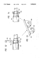
- FIG. 8 is a perspective view of a developing flange and a bearing before they are fitted together;
- FIG. 9 is a longitudinal view of the developing sleeve and therearound, according to the second embodiment of the present invention, in a condition that the second bearing is arranged at a second position;
- FIG. 10 is a partial sectional view showing a condition that a bearing is fitted on a first position of a developing flange, according to a third embodiment of the present invention.
- FIG. 11 is a partial sectional view showing a condition that the bearing is fitted on a second position of the developing flange, according to the third embodiment of the present invention.
- FIG. 12 is a partial sectional view showing a condition that a first bearing portion of a bearing is fitted on a first position of a developing flange, according to a fourth embodiment of the present invention.
- FIG. 13 is a perspective view of the bearing of FIG. 12.
- FIG. 14 is a partial sectional view showing a condition that a second bearing portion of the bearing is fitted on a second position of the developing flange, according to the fourth embodiment of the present invention.
- a process cartridge utilizing "reusable parts which can still be used even after a service life of a process cartridge is expired" will be explained.
- the present invention is not limited to such process cartridge, but may be applied to an image forming system utilizing reusable parts.
- a service life of a process cartridge is expired means that, for example, a service life of a photosensitive member included in the cartridge is expired or developer included in the cartridge becomes empty or is used up.
- reusable parts may be used with the body of the system or cartridge.
- Process means for forming an image such as a developing device 11, a primary charger 12 and a cleaning device 13 are arranged around a photosensitive drum 10 acting as an image bearing member. These process means are bodily incorporated into a housing 14a of a process cartridge 14 which can removably be mounted within an image forming system 1.
- a transfer charger 15 is arranged below the photosensitive drum 10. Further, a sheet supply tray 16, sheet supply rollers 17 and regist rollers 18 are disposed at an upstream side (sheet supplying side) of the transfer charger 15, and a transfer sheet guide 19, a fixing device 20, sheet ejector rollers 21 and a sheet ejection tray 22 are disposed at a downstream side (sheet ejecting side) of the transfer charger. Further, a lighting lamp 23 for illuminating an original document, and a short focus optical element array 24 for exposing the photosensitive drum 10 with light reflected from the original are arranged above the photosensitive drum 10. In addition, an original support plate 25 shiftable in direction shown by the double arrow is arranged on the frame 1 of the image forming system.
- the toner image on the photosensitive drum 10 is transferred onto the transfer sheet P.
- the transfer sheet P to which the toner image was transferred is sent to the fixing device 20, where the toner image is permanently fixed to the sheet. Thereafter, the transfer sheet is ejected by the ejector rollers 21 onto the ejection tray 22.
- the residual toner remaining on the photosensitive drum 10 is removed by the cleaning device 13, thus preparing it for the next image formation.
- the cleaning device 13 comprises a cleaning container 132 for collecting the residual toner on the photosensitive drum 10 which is a moving part, a cleaning blade, which is an abutment part, for removing the residual toner on the photosensitive drum 10, and a receiving sheet 134 for guiding the removed waste toner to the cleaning container (residual matter containing member) 132.
- both end walls 132a of the cleaning container 132 i.e., in a plane perpendicular to an axial direction of the photosensitive drum 10 and extend toward the photosensitive drum 10 to rotatably support end shafts 141, 142 of the photosensitive drum 10.
- the primary charger 12 is attached to the extended end walls 132a.
- the cleaning blade comprises a metal plate 131b acting as a second support member, and an urethane rubber portion 131a which are adhered to each other by an adhesive, and the urethane rubber portion 131a has a predetermined free length L.
- the free length L is a distance between a free end of the metal plate 132b and an abutment position where the urethane rubber portion 131a is abutted against the photosensitive drum.
- the cleaning container 132 has an opening 132h open to the photosensitive drum 10, and attachment surfaces 132g for attaching the cleaning blade thereto are provided at edges of the opening 132h.
- the cleaning container 132 serves also as a support member for the cleaning blade 131.
- the metal plate 131b of the cleaning blade is abutted against and attached to the attachment surfaces 132f.
- the cleaning container 132 is provided at its both end portion with three holes 132c, 132d, respectively, into which pins for positioning the cleaning blade 131 are inserted.
- Each of the holes 132c is paired with the corresponding hole 132d, and positions of these holes 132c, 132d approach toward the free end of the blade 131 as they approach to the ends of the cleaning container.
- a left end portion of the metal plate 131b of the cleaning blade 131 has three positioning holes 131c aligned in a longitudinal direction of the cleaning blade and formed in the metal plate at a pitch n equal to a pitch n between the holes 132c of the cleaning container 132 in the longitudinal direction thereof. Further, as shown in FIG. 2, a positioning slot 131d is formed in a left end portion of the metal plate 131b. Attachment slots 131e, 131f are formed in the right and left end portions of the metal plate in parallel with the row of the positioning holes 131c and the slot 131d, respectively.
- the holes 131c and slot 131d serve to position the blade 131 with respect to the support member 132
- the slots 131e, 131f serve to bias the blade toward the support member 132 for preventing the turn-up of the blade due to the rotation of the photosensitive drum.
- the central left hole 132d of the cleaning container 132 will appear in the positioning slot 131d of the cleaning blade at a central portion thereof. In this position, the cleaning blade 131 is in an intermediate position.
- the cleaning blade 131 is in an advanced position.
- the attachment slots 131e, 132f of the cleaning blade are aligned with any one of the lower holes 132e, 132f of the attachment surfaces 132g, respectively, without fail.
- positioning pins are inserted into the innermost holes 132c, 132d of the cleaning container 132 and then are fitted into the corresponding positioning holes 131c and slot 131d of the metal plate 131b of the cleaning blade, thus positioning the cleaning blade 131 with respect to the cleaning container 132.
- the tapping screws are passed through the attachment slots 131e, 131f of the cleaning blade 131 and are threaded into the associated lower holes 132e, 132f.
- the degree of the creep of the urethane rubber portion 131a of the second-hand cleaning blade is measured, and the positions of the positioning pins are displaced outwardly in accordance with the degree of the creep so that the cleaning blade is attached to the cleaning container 132 in the intermediate or advanced position.
- a tip edge of the urethane rubber portion 131a of the cleaning blade 131 urged against the photosensitive drum 10 is sometimes partially broken to produce about a 20 ⁇ m variation in the uniformity of the edge as indicated by 131g. So, before the second hand cleaning blade is reused, the tip edge of the cleaning blade is cut by about 30 ⁇ m in the free length direction.
- the cut-off amount is preferably in a range of 1 ⁇ m-1 mm in consideration of the desired urging force of the blade against the photosensitive drum.
- the positioning pins are inserted into, for example, the outermost holes so that the cleaning blade 131 is attached to the cleaning container 132 in the advanced position.
- the tip edge (portion to be urged against the photosensitive drum) of the second-hand cleaning blade by uniformly cutting the tip edge (portion to be urged against the photosensitive drum) of the second-hand cleaning blade by 1 ⁇ m-1 mm in the free length direction before it is reused in a process cartridge, and by displacing the attachment position of the cleaning blade toward the photosensitive drum in accordance with the cut-off amount, it is possible to avoid the problem due to the broken edge of the blade and to reuse the blade effectively. Further, when the cut-out amount of the blade edge is previously coincided with the pitch between the positioning holes, the number of the reusage of the blade and accordingly the cartridge can be easily ascertained.
- the present invention can also solve the problem occurred by reusage of a developing device, as well as the cleaning device. That is to say, since surfaces of a sleeve flange and a bearing of the developing device are gradually worn while the developing device is being used for a long time, when the sleeve flange is reused in a process cartridge, it is feared that the reused sleeve flange is not properly fitted into a new bearing.
- An embodiment described hereinbelow aims to solve this problem so that a developing sleeve of the developing device can be reused effectively.
- FIGS. 6 and 7 are cross-sectional view and a longitudinal view of a developing sleeve of a developing device for supplying toner on the photosensitive drum, respectively.
- a pipe-shaped developing sleeve 201 is disposed in a developer chamber 203.
- a magnet roller 204 comprising magnets having a plurality of magnetic poles is contained within the developing sleeve 201.
- a developer blade 202 is urged against the developing sleeve 201.
- the developer blade 202 is attached to a developer container 205.
- the developing sleeve 201 is biased toward the photosensitive drum 10 acting as an image bearing member by means of a biasing means (not shown) while creating a predetermined clearance therebetween by spacer rollers 207a, 207b acting as clearance keeping members.
- the toner or developer is supplied from a toner container by a conveying means (not shown) or free drop to the developer chamber 203 through an opening 208 of the developer chamber 203.
- the toner in the developer chamber 203 is attracted by one (N 1 ) of the magnetic poles of the magnet roller 204, thus being agitated by the rotating developing sleeve 201 to be gradually charged.
- a part of the toner is conveyed in a direction shown by the arrow in FIG. 6 by the rotation of the developing sleeve 201 and is sent between the developing sleeve and the developer blade 202, where the toner is strongly urged against the developing sleeve 201 by the developer blade 202, thus increasing the charge amount of the toner abruptly.
- the charged toner is then discharged out of the developer chamber 203 by the rotation of the developing sleeve 201.
- the developer blade 202 serves to not only charge the toner for increasing the charge amount of the toner, but also to regulate a thickness of a toner layer around the developing sleeve 201.
- many of the developing sleeves are made from conductive material such as aluminium, and, as shown in FIG. 7, a bias plate 209 is incorporated into the interior of a pipe of the developing sleeve at its one end so that the developing bias is applied to the developing sleeve 201 from a development bias supply source (not shown) of the image forming system.
- the toner conveyed from the developer chamber 203 by the developing sleeve 201 is transferred onto the electrostatic latent image on the photosensitive drum 10 by the development bias, thus developing the electrostatic latent image with the toner.
- the toner not used for the development is returned to the developer chamber 203 by the rotation of the developing sleeve 201.
- a flange 213 is fitted into the pipe of the developing sleeve 201 and is rotatably supported by a bearing 211a (see FIG. 8).
- the spacer roller 207b is fitted on the pipe of the developing sleeve.
- the spacer roller is rotatably supported by a bearing 211b.
- the magnet roller 204 has a shaft extension which is fixedly mounted on the developer container 205.
- the flange 213 of the developing sleeve 201 is rotatably supported by the bearing 211a, and, thus, when the image forming system is operated and the developing sleeve is rotated, a peripheral surface of the flange 213 is frictionally slid with respect to an inner surface of the bearing 211a.
- a bearing slidingly contacted with a flange of a developing sleeve can be shifted from a first position before a process cartridge is reused to a second position after the process cartridge is reused.
- the second embodiment will be fully explained hereinafter.
- FIG. 7 is a longitudinal view of a developing device before a process cartridge of an image forming system is reused
- FIG. 9 is a longitudinal view of the developing device after the cartridge is reproduced or reused. It should be noted that, both before and after reuse, a flange 250 is fitted in the developing sleeve 201.
- a first sliding portion (abutment portion) 249 of the flange 250 is supported by a first bearing 253.
- a second sliding portion 251 of the flange 250 is supported by a second bearing 252 which is constituted by members different from those of the first bearing 253.
- a diameter of the second sliding portion is smaller than that of the first sliding portion 249, and, accordingly, an inner diameter of the second bearing 252 is smaller than that of the first bearing 253.
- the attachment accuracy between the first sliding portion 249 of the flange 250 and the bearing 253 is the same as that between the second sliding portion 251 and the bearing 252.
- the same technical effect can be obtained even when there are three or more sliding portions of the sleeve flange 250, if the same number of bearings having the corresponding inner diameters are prepared, the developing device can be reused by plural times corresponding to the number of the bearings.
- a bearing 255 has a construction as shown in FIGS. 10 and 11.
- the bearing 255 has two sliding surfaces (260, 261), and the sleeve flange 250 and the sleeve 201 are held by a sliding portion 261 of the bearing 255 having an inner diameter corresponding to a diameter of a first sliding surface 249 of the sleeve flange 250.
- the sum l 1 of lengths of the first and second sliding surfaces 249, 251 of the sleeve flange 250 along a longitudinal direction of the developing sleeve is selected to be smaller than a longitudinal length l 2 of the sliding portion 260 of the bearing 255 (i.e., l 1 ⁇ l 2 ).
- l 1 ⁇ l 2 the second sliding portion 251 of the sleeve flange 250 will interfere with the second sliding portion 261 of the bearing 255.
- the bearing 255 is once dismounted, and then is mounted again so that the second sliding portion 261 of the bearing 255 is fitted onto the second sliding surface 251 of the sleeve flange 250.
- the third embodiment is more economical than the second embodiment.
- FIGS. 12 to 14 a fourth embodiment of the present invention will be explained with reference to FIGS. 12 to 14. Also in this embodiment, the constructions of the sleeve 201 and the sleeve flange 250 are the same as those in the second and third embodiments.
- a bra ring 256 has fitting portions or holes 257, 258 corresponding to the first and second sliding surfaces 249, 251 of the sleeve flange 250.
- FIG. 12 shown a condition that the first sliding surface 249 of the sleeve flange 250 is fitted into and supported by the first fitting hole 257 of the bearing 256.
- the second fitting hole 258 of the bearing 256 is disposed along a direction that is perpendicular to an axis of the sleeve and that is not interfered with the photosensitive drum.
- the bearing 256 is once dismounted from the sleeve flange 250 and is divided into two pieces along a tearing line m shown in FIG. 13. Thereafter, by fitting the bearing portion 259 having the second fitting hole 258 onto the second sliding surface 251 of the sleeve flange 250 as shown in FIG. 14, the sleeve flange can be supported by the bearing portion properly.
- This fourth embodiment is effective in the case where there is no sufficient space along the longitudinal direction of the sleeve unlike the third embodiment.
- the bearing 256 has discrete fitting holes corresponding to the sliding surfaces 249, 251 of the sleeve flange 250 and can be utilized even when it is divided into two pieces as in the above example, the same technical effect can be obtained.
Abstract
A process cartridge includes a rotatable rotary member having a plurality of bearing attachment portions to which bearings are attachable. The plurality of bearing attachment portions are provided on the rotary member with different diameters. A method of reusing a rotation member that is supported at one of a plurality of coaxial rotation surfaces having different diameters includes detaching one of a plurality of bearing members that supports the rotation member at the one of the plurality of coaxial rotation surfaces. Another of the plurality of bearing members is then attached at a corresponding other of the plurality of coaxial rotation surfaces that has a different diameter than the one of the plurality of coaxial rotation surfaces.
Description
This application is a continuation of application Ser. No. 07/863,755, filed Apr. 6, 1992, now abandoned.
1. Field of the Invention
The present invention relates to an image forming system such as a copying machine, printer and the like, and a process cartridge removably mountable within such image forming system, and more particularly, it relates to an image forming system and a process cartridge each having parts which are reusable even after the disassembling or destruction of the image forming system and the process cartridge.
2. Related Background Art
In an image forming system and a process cartridge removably mountable within the image forming system, it is preferable that parts or elements are reused as much as possible from the view points of economization and/or environment protection. That is to say, various parts which constitute the process cartridge a previously used image forming system that has been withdrawn from use, for example, because the photosensitive member, has worn out are preferably reused in the manufacture of new process cartridges and image forming systems.
However, in the past, it was difficult to reuse abutment members abutting or urging against moving parts, since such abutment members and/or moving parts had been worn due to the frictional sliding therebetween.
For example, the case of a cleaning blade and a developer blade which are urged against a photosensitive drum will be considered. In the case of the cleaning blade, since it is made of urethane rubber or similar materials which are subjected to creep for a long time, if it is reused, a contacting pressure between the cleaning blade and the photosensitive drum, and a penetrating amount of the cleaning blade against the drum are decreased in comparison with the desired levels. Thus, when the cleaning blade is reused, the residual toner remaining on the photosensitive drum cannot be removed completely, with the result that the toner still remaining on the drum may generate black stripes on a copied image. On the other hand, when the developer blade regulating an amount of developer (toner) adhering onto a developing roller is reused, the charge amount of the developer is decreased, thus reducing the image density.
Incidentally, in image forming systems not utilizing process cartridges, if such cleaning blade and/or developer blade are reused, the same problems will occur.
The present invention aims to eliminate the above-mentioned conventional drawback, and has an object to provide a process cartridge and an image forming system which utilizes reusable parts.
Another object of the present invention is to provide a process cartridge and an image forming system which comprise a moving member, an abutment member urged against the moving member, and a means capable of mounting the abutment member at a first position and a second position different from the first position.
The other objects of the present invention will be apparent from the following descriptions.
FIG. 1 is an elevational sectional view of a process cartridge according to the present invention;
FIG. 2 is a view showing a cleaning blade used with an image forming system and a process cartridge according to a first embodiment of the present invention;
FIG. 3 is a view showing a residual matters collecting container according to a first embodiment of the present invention;
FIG. 4 is a view of the process cartridge looked at from a direction shown by the arrow A in FIG. 1;
FIG. 5 is an elevational sectional view of an image forming system according to the present invention;
FIG. 6 is a sectional view of a developing sleeve and therearound, according to the present invention;
FIG. 7 is a longitudinal view of a developing sleeve and therearound, according to a second embodiment of the present invention, in a condition that a second bearing is arranged at a first position;
FIG. 8 is a perspective view of a developing flange and a bearing before they are fitted together;
FIG. 9 is a longitudinal view of the developing sleeve and therearound, according to the second embodiment of the present invention, in a condition that the second bearing is arranged at a second position;
FIG. 10 is a partial sectional view showing a condition that a bearing is fitted on a first position of a developing flange, according to a third embodiment of the present invention;
FIG. 11 is a partial sectional view showing a condition that the bearing is fitted on a second position of the developing flange, according to the third embodiment of the present invention;
FIG. 12 is a partial sectional view showing a condition that a first bearing portion of a bearing is fitted on a first position of a developing flange, according to a fourth embodiment of the present invention;
FIG. 13 is a perspective view of the bearing of FIG. 12; and
FIG. 14 is a partial sectional view showing a condition that a second bearing portion of the bearing is fitted on a second position of the developing flange, according to the fourth embodiment of the present invention.
The present invention will now be explained in connection with embodiments thereof with reference to the accompanying drawings. Incidentally, hereinafter, a process cartridge utilizing "reusable parts which can still be used even after a service life of a process cartridge is expired" will be explained. However, the present invention is not limited to such process cartridge, but may be applied to an image forming system utilizing reusable parts. Here, the fact that a service life of a process cartridge is expired means that, for example, a service life of a photosensitive member included in the cartridge is expired or developer included in the cartridge becomes empty or is used up. Further, reusable parts may be used with the body of the system or cartridge.
First of all, an image forming system will briefly be explained with reference to FIG. 5.
Process means for forming an image, such as a developing device 11, a primary charger 12 and a cleaning device 13 are arranged around a photosensitive drum 10 acting as an image bearing member. These process means are bodily incorporated into a housing 14a of a process cartridge 14 which can removably be mounted within an image forming system 1. In this way, when it is desired to perform the maintenance such as the replacement of the photosensitive drum (image bearing member) 10, the replacement of the developing device 11 or the replenishment of developer (toner t), the cleaning of a discharging wire of the primary charger 12, the replacement of the cleaning device 13 fitted with the waste toner, the adjustment or the replacement of various devices disposed around the photosensitive drum 10, or the like, which require skillful techniques and knowledge that to make the operator's handling difficult, the operator can perform such maintenance easily by replacing the whole process cartridge with a new one.
Within the process cartridge 14, a transfer charger 15 is arranged below the photosensitive drum 10. Further, a sheet supply tray 16, sheet supply rollers 17 and regist rollers 18 are disposed at an upstream side (sheet supplying side) of the transfer charger 15, and a transfer sheet guide 19, a fixing device 20, sheet ejector rollers 21 and a sheet ejection tray 22 are disposed at a downstream side (sheet ejecting side) of the transfer charger. Further, a lighting lamp 23 for illuminating an original document, and a short focus optical element array 24 for exposing the photosensitive drum 10 with light reflected from the original are arranged above the photosensitive drum 10. In addition, an original support plate 25 shiftable in direction shown by the double arrow is arranged on the frame 1 of the image forming system.
When a light image from the original resting on the original support plate 25 is sent, via the lighting lamp 23 and the short focus optical element array 24, to the photosensitive drum 10 uniformly charged by the primary charger 12, an electrostatic latent image is formed on the photosensitive drum 10. The electrostatic latent image is sent to the developing device 11 as the photosensitive drum is further rotated, and is developed by the developing device 11 with the toner t to form a toner image. Then, the toner image is transferred onto a transfer sheet P by the transfer charger 15. That is to say, the transfer sheet P is supplied from the sheet supply tray 16 by the sheet supply rollers 17 to reach the regist roller 18, and then is interposed between the photosensitive drum 10 and the transfer charger 15 in registration with the toner image on the drum. Thus, the toner image on the photosensitive drum 10 is transferred onto the transfer sheet P. The transfer sheet P to which the toner image was transferred is sent to the fixing device 20, where the toner image is permanently fixed to the sheet. Thereafter, the transfer sheet is ejected by the ejector rollers 21 onto the ejection tray 22. On the other hand, after the transferring operation, the residual toner remaining on the photosensitive drum 10 is removed by the cleaning device 13, thus preparing it for the next image formation.
Next, a first embodiment of the present invention will be explained with reference to FIGS. 1 to 4.
The cleaning device 13 comprises a cleaning container 132 for collecting the residual toner on the photosensitive drum 10 which is a moving part, a cleaning blade, which is an abutment part, for removing the residual toner on the photosensitive drum 10, and a receiving sheet 134 for guiding the removed waste toner to the cleaning container (residual matter containing member) 132. As shown in FIG. 4, both end walls 132a of the cleaning container 132, i.e., in a plane perpendicular to an axial direction of the photosensitive drum 10 and extend toward the photosensitive drum 10 to rotatably support end shafts 141, 142 of the photosensitive drum 10. Further, the primary charger 12 is attached to the extended end walls 132a. The cleaning blade comprises a metal plate 131b acting as a second support member, and an urethane rubber portion 131a which are adhered to each other by an adhesive, and the urethane rubber portion 131a has a predetermined free length L. Now, the free length L is a distance between a free end of the metal plate 132b and an abutment position where the urethane rubber portion 131a is abutted against the photosensitive drum.
The cleaning container 132 has an opening 132h open to the photosensitive drum 10, and attachment surfaces 132g for attaching the cleaning blade thereto are provided at edges of the opening 132h. Thus, the cleaning container 132 serves also as a support member for the cleaning blade 131. The metal plate 131b of the cleaning blade is abutted against and attached to the attachment surfaces 132f.
The cleaning container 132 is provided at its both end portion with three holes 132c, 132d, respectively, into which pins for positioning the cleaning blade 131 are inserted. Each of the holes 132c is paired with the corresponding hole 132d, and positions of these holes 132c, 132d approach toward the free end of the blade 131 as they approach to the ends of the cleaning container. Below these holes 132c, 132d, are holes 132e, 132f for cooperating with tapping screws to secure the cleaning blade 131.
A left end portion of the metal plate 131b of the cleaning blade 131 has three positioning holes 131c aligned in a longitudinal direction of the cleaning blade and formed in the metal plate at a pitch n equal to a pitch n between the holes 132c of the cleaning container 132 in the longitudinal direction thereof. Further, as shown in FIG. 2, a positioning slot 131d is formed in a left end portion of the metal plate 131b. Attachment slots 131e, 131f are formed in the right and left end portions of the metal plate in parallel with the row of the positioning holes 131c and the slot 131d, respectively. That is to say, the holes 131c and slot 131d serve to position the blade 131 with respect to the support member 132, and the slots 131e, 131f serve to bias the blade toward the support member 132 for preventing the turn-up of the blade due to the rotation of the photosensitive drum. When the metal plate 131b of the cleaning blade is abutted aginst the attachment surfaces 132e of the cleaning container 132, by aligning the innermost positioning hole 131c of the cleaning blade 131 with the highest hole 132c and by aligning the left positioning slot 131d of the cleaning blade 131 with the highest hole 132d of the cleaning container 132, the highest left hole 132d of the cleaning container 132 will appear in the positioning slot 131d of the cleaning blade at the right end thereof. In this position, the cleaning blade 131 has been retracted.
Similarly, by aligning the central positioning hole 131c of the cleaning blade 131 with the central hole 132c of the cleaning container 132 and by aligning the left positioning slot 131d of the cleaning blade 131 with the central left hole 132d of the cleaning container 132, the central left hole 132d of the cleaning container 132 will appear in the positioning slot 131d of the cleaning blade at a central portion thereof. In this position, the cleaning blade 131 is in an intermediate position.
Similarly, by aligning the outermost positioning hole 131c of the cleaning blade 131 with the lowest hole 132c of the cleaning container 132 and by aligning the positioning slot 131d of the cleaning blade with the lowest hole 132d, the lowest hole 132d of the cleaning container 132 will appear in the positioning slot 131d at a left end thereof. In this position, the cleaning blade 131 is in an advanced position. Now, since the lower holes 132e, 132f for the tapping screws are formed in the attachment surface 132g of the cleaning container 132 below the holes 132c, 132d at a vertical distance or pitch m, respectively, and the attachment slots 131e, 132f are formed in the cleaning blade 131 below the positioning holes 131c and the slot 131d at the same vertical distance or pitch m, respectively, when the metal plate 131b of the cleaning blade 131 is abutted against the attachment surfaces 132g of the cleaning container 132 as mentioned above, the attachment slots 131e, 131f of the cleaning blade are aligned with any one of the lower holes 132e, 132f of the attachment surfaces 132g, respectively, without fail.
When a new cleaning blade 131 is used, since there is no creep in the urethane rubber portion 131a, positioning pins (not shown) are inserted into the innermost holes 132c, 132d of the cleaning container 132 and then are fitted into the corresponding positioning holes 131c and slot 131d of the metal plate 131b of the cleaning blade, thus positioning the cleaning blade 131 with respect to the cleaning container 132. After the positioning, the tapping screws are passed through the attachment slots 131e, 131f of the cleaning blade 131 and are threaded into the associated lower holes 132e, 132f. On the other hand, for example, when a previously used cleaning blade is reused, the degree of the creep of the urethane rubber portion 131a of the second-hand cleaning blade is measured, and the positions of the positioning pins are displaced outwardly in accordance with the degree of the creep so that the cleaning blade is attached to the cleaning container 132 in the intermediate or advanced position.
Further, if the blade is used for a long time, a tip edge of the urethane rubber portion 131a of the cleaning blade 131 urged against the photosensitive drum 10 is sometimes partially broken to produce about a 20 μm variation in the uniformity of the edge as indicated by 131g. So, before the second hand cleaning blade is reused, the tip edge of the cleaning blade is cut by about 30 μm in the free length direction. The cut-off amount is preferably in a range of 1 μm-1 mm in consideration of the desired urging force of the blade against the photosensitive drum. In this case, since the penetrating amount of the blade (when assembled) is decreased in accordance with the cut-off amount, the positioning pins are inserted into, for example, the outermost holes so that the cleaning blade 131 is attached to the cleaning container 132 in the advanced position.
As mentioned above, by changing the attachment position of the cleaning blade 131 to the cleaning container 132 in accordance with whether a new or second-hand cleaning blade is being used, it is possible to always maintain the urging force and the penetrating amount of the cleaning blade against the photosensitive drum constant. In this way, the conventional drawback regarding the poor image due to the creep of the reused cleaning blade can be eliminated.
As mentioned above, by uniformly cutting the tip edge (portion to be urged against the photosensitive drum) of the second-hand cleaning blade by 1 μm-1 mm in the free length direction before it is reused in a process cartridge, and by displacing the attachment position of the cleaning blade toward the photosensitive drum in accordance with the cut-off amount, it is possible to avoid the problem due to the broken edge of the blade and to reuse the blade effectively. Further, when the cut-out amount of the blade edge is previously coincided with the pitch between the positioning holes, the number of the reusage of the blade and accordingly the cartridge can be easily ascertained.
Further, the present invention can also solve the problem occurred by reusage of a developing device, as well as the cleaning device. That is to say, since surfaces of a sleeve flange and a bearing of the developing device are gradually worn while the developing device is being used for a long time, when the sleeve flange is reused in a process cartridge, it is feared that the reused sleeve flange is not properly fitted into a new bearing. An embodiment described hereinbelow aims to solve this problem so that a developing sleeve of the developing device can be reused effectively.
FIGS. 6 and 7 are cross-sectional view and a longitudinal view of a developing sleeve of a developing device for supplying toner on the photosensitive drum, respectively.
As shown in FIGS. 6 and 7, a pipe-shaped developing sleeve 201 is disposed in a developer chamber 203. A magnet roller 204 comprising magnets having a plurality of magnetic poles is contained within the developing sleeve 201. A developer blade 202 is urged against the developing sleeve 201. The developer blade 202 is attached to a developer container 205. The developing sleeve 201 is biased toward the photosensitive drum 10 acting as an image bearing member by means of a biasing means (not shown) while creating a predetermined clearance therebetween by spacer rollers 207a, 207b acting as clearance keeping members.
The toner or developer is supplied from a toner container by a conveying means (not shown) or free drop to the developer chamber 203 through an opening 208 of the developer chamber 203. The toner in the developer chamber 203 is attracted by one (N1) of the magnetic poles of the magnet roller 204, thus being agitated by the rotating developing sleeve 201 to be gradually charged. A part of the toner is conveyed in a direction shown by the arrow in FIG. 6 by the rotation of the developing sleeve 201 and is sent between the developing sleeve and the developer blade 202, where the toner is strongly urged against the developing sleeve 201 by the developer blade 202, thus increasing the charge amount of the toner abruptly. The charged toner is then discharged out of the developer chamber 203 by the rotation of the developing sleeve 201. Incidentally, the developer blade 202 serves to not only charge the toner for increasing the charge amount of the toner, but also to regulate a thickness of a toner layer around the developing sleeve 201.
By the way, many of the developing sleeves are made from conductive material such as aluminium, and, as shown in FIG. 7, a bias plate 209 is incorporated into the interior of a pipe of the developing sleeve at its one end so that the developing bias is applied to the developing sleeve 201 from a development bias supply source (not shown) of the image forming system.
Accordingly, the toner conveyed from the developer chamber 203 by the developing sleeve 201 is transferred onto the electrostatic latent image on the photosensitive drum 10 by the development bias, thus developing the electrostatic latent image with the toner. Incidentally, the toner not used for the development is returned to the developer chamber 203 by the rotation of the developing sleeve 201.
At the other end of the developing sleeve 201, a flange 213 is fitted into the pipe of the developing sleeve 201 and is rotatably supported by a bearing 211a (see FIG. 8). On the other hand, as mentioned above, at other end of the developing sleeve 201, the spacer roller 207b is fitted on the pipe of the developing sleeve. The spacer roller is rotatably supported by a bearing 211b. Further, the magnet roller 204 has a shaft extension which is fixedly mounted on the developer container 205. As mentioned above, the flange 213 of the developing sleeve 201 is rotatably supported by the bearing 211a, and, thus, when the image forming system is operated and the developing sleeve is rotated, a peripheral surface of the flange 213 is frictionally slid with respect to an inner surface of the bearing 211a.
Thus, in a second embodiment of the present invention, a bearing slidingly contacted with a flange of a developing sleeve can be shifted from a first position before a process cartridge is reused to a second position after the process cartridge is reused. The second embodiment will be fully explained hereinafter.
FIG. 7 is a longitudinal view of a developing device before a process cartridge of an image forming system is reused, and FIG. 9 is a longitudinal view of the developing device after the cartridge is reproduced or reused. It should be noted that, both before and after reuse, a flange 250 is fitted in the developing sleeve 201.
In FIG. 7, a first sliding portion (abutment portion) 249 of the flange 250 is supported by a first bearing 253. After reuse, as shown in FIG. 9, a second sliding portion 251 of the flange 250 is supported by a second bearing 252 which is constituted by members different from those of the first bearing 253. A diameter of the second sliding portion is smaller than that of the first sliding portion 249, and, accordingly, an inner diameter of the second bearing 252 is smaller than that of the first bearing 253. Further, the attachment accuracy between the first sliding portion 249 of the flange 250 and the bearing 253 is the same as that between the second sliding portion 251 and the bearing 252.
As mentioned above, merely by changing the bearing which is relatively cheap when the process cartridge reused or the image forming system is reproduced, it is possible to reuse the sleeve and the sleeve flange 250.
Incidentally, even when the sleeve flange 250 is situated on the sleeve 201 (i.e., when the there is no flange 250 and the sleeve itself is supported by the bearing), the same technical effect can be obtained. Further, even when there are three or more sliding portions of the sleeve flange 250, if the same number of bearings having the corresponding inner diameters are prepared, the developing device can be reused by plural times corresponding to the number of the bearings.
Next, a third embodiment of the present invention will be explained.
In the above-mentioned second embodiment, while only the developing sleeve and the sleeve flange could be reused, in this third embodiment, the bearing can also be reused. This embodiment will be explained with reference to FIGS. 10 and 11.
The constructions of a sleeve 201 and a sleeve flange 250 are the same as those in the second embodiment. A bearing 255 has a construction as shown in FIGS. 10 and 11. In FIG. 10, the bearing 255 has two sliding surfaces (260, 261), and the sleeve flange 250 and the sleeve 201 are held by a sliding portion 261 of the bearing 255 having an inner diameter corresponding to a diameter of a first sliding surface 249 of the sleeve flange 250.
Now, the sum l1 of lengths of the first and second sliding surfaces 249, 251 of the sleeve flange 250 along a longitudinal direction of the developing sleeve is selected to be smaller than a longitudinal length l2 of the sliding portion 260 of the bearing 255 (i.e., l1 <l2). The reason is that, in FIG. 10, if l1 ≧l2 the second sliding portion 251 of the sleeve flange 250 will interfere with the second sliding portion 261 of the bearing 255.
Now, when the process cartridge is reused or the image forming system is reproduced, if the dimensional accuracy of the first sliding surface 249 of the sleeve flange 250 and the sliding portion 260 of the bearing 255 is worsened due to the wear generated by the sliding contact therebetween, as shown in FIG. 11, the bearing 255 is once dismounted, and then is mounted again so that the second sliding portion 261 of the bearing 255 is fitted onto the second sliding surface 251 of the sleeve flange 250.
In this way, since not only the sleeve 201 and the sleeve flange 250 but also the bearing 255 can be reused, the third embodiment is more economical than the second embodiment.
Incidentally, of course, it should be understood that, when any non-sliding surface (not shown) such as taper, R and the like is formed between the first and second sliding surfaces of the flange, the above-mentioned relation regarding l1 <l2 should be changed to (l1 +x)<L2 (where, x is a longitudinal length of the non-sliding surface).
Next, a fourth embodiment of the present invention will be explained with reference to FIGS. 12 to 14. Also in this embodiment, the constructions of the sleeve 201 and the sleeve flange 250 are the same as those in the second and third embodiments.
In FIG. 12, a bra ring 256 has fitting portions or holes 257, 258 corresponding to the first and second sliding surfaces 249, 251 of the sleeve flange 250. FIG. 12 shown a condition that the first sliding surface 249 of the sleeve flange 250 is fitted into and supported by the first fitting hole 257 of the bearing 256. In this case, the second fitting hole 258 of the bearing 256 is disposed along a direction that is perpendicular to an axis of the sleeve and that is not interfered with the photosensitive drum.
When the dimensional accuracy of the fitting portion of the bearing is worsened in use due to the frictional wear or when the second-hand developing sleeve is reused, the bearing 256 is once dismounted from the sleeve flange 250 and is divided into two pieces along a tearing line m shown in FIG. 13. Thereafter, by fitting the bearing portion 259 having the second fitting hole 258 onto the second sliding surface 251 of the sleeve flange 250 as shown in FIG. 14, the sleeve flange can be supported by the bearing portion properly.
In this way, the bearing can also be reused. This fourth embodiment is effective in the case where there is no sufficient space along the longitudinal direction of the sleeve unlike the third embodiment.
Further, so long as the bearing 256 has discrete fitting holes corresponding to the sliding surfaces 249, 251 of the sleeve flange 250 and can be utilized even when it is divided into two pieces as in the above example, the same technical effect can be obtained.
Claims (13)
1. A method of reusing a rotation member used in an image forming apparatus, wherein the rotation member is supported at one of a plurality of coaxial rotation surfaces, each of which has a different diameter and is shifted axially from one another, by a corresponding support surface of one of a plurality of bearing members, comprising the steps of:
detaching the one of the plurality of bearing members that supports the rotation member at the one of the plurality of coaxial rotation surfaces; and
attaching another of the plurality of bearing members at a corresponding other of the plurality of coaxial rotation surfaces that has a different diameter than the one of the plurality of coaxial rotation surfaces.
2. A method according to claim 1, wherein the rotation member comprises a developing sleeve for conveying toner used for developing a latent image formed on a photosensitive member and said detaching step comprises detaching the one of the plurality of bearing members from the developing sleeve.
3. A method according to claim 2, wherein the other of the plurality of coaxial rotation surfaces to which the other bearing member is attached has a smaller diameter than the one of the coaxial rotation surfaces from which the one bearing member is detached.
4. A method according to claim 2, wherein said attaching step comprises attaching a bearing member having a diameter smaller than the diameter of the one bearing member detached in said detaching step.
5. A method according to claim 1, wherein the rotation member comprises a pipe having a flange fitted to an inner surface thereof and the one of the plurality of bearing members supports the flange, and said detaching step comprises detaching the one of the plurality of bearing members from the flange.
6. A method according to claim 1, wherein the other of the plurality of coaxial rotation surfaces to which the other bearing member is attached has a smaller diameter than the one of the coaxial rotation surfaces from which the one bearing member is detached.
7. A method according to claim 1, wherein said attaching step comprises attaching a bearing member having a diameter smaller than the diameter of the one bearing member detached in said detaching step.
8. A method of reusing a developing sleeve for use in an image forming apparatus for supplying a toner to a photosensitive member to develop a latent image formed thereon, wherein the developing sleeve is supported at one of a plurality of coaxial rotation surfaces, each of which has a different diameter and is shifted axially from one another, by a corresponding support surface of one of a plurality of bearing members, said method comprising the steps of:
detaching the one of the plurality of bearing members that supports the developing sleeve at the one of the plurality of coaxial rotation surfaces; and
attaching another of the plurality of bearing members at a corresponding other of the plurality of coaxial rotation surfaces that has a different diameter than the one of the plurality of coaxial rotation surfaces.
9. A method according to claim 8, wherein the other of the plurality of coaxial rotation surfaces to which the other bearing member is attached has a smaller diameter than the one of the coaxial rotation surfaces from which the one bearing member is detached.
10. A method according to claim 8, wherein said attaching step comprises attaching a bearing member having a diameter smaller than the diameter of the one bearing member detached in said detaching step.
11. A method according to claim 8, wherein the developing sleeve comprises a pipe having a flange fitted to an inner surface thereof and the one of the plurality of bearing members supports the flange, and said detaching step comprises detaching the one of the plurality of bearing members from the flange.
12. A method according to claim 11, wherein the other of the plurality of coaxial rotation surfaces to which the other bearing member is attached has a smaller diameter than the one of the coaxial rotation surfaces from which the one bearing member is detached.
13. A method according to claim 11, wherein said attaching step comprises attaching a bearing member having a diameter smaller than the diameter of the one bearing member detached in said detaching step.
Priority Applications (1)
| Application Number | Priority Date | Filing Date | Title |
|---|---|---|---|
| US08/197,571 US5528341A (en) | 1991-04-08 | 1994-02-17 | Process cartridge with rotary member having bearing attachment portions of different diameters, and method for refusing such a rotary member |
Applications Claiming Priority (6)
| Application Number | Priority Date | Filing Date | Title |
|---|---|---|---|
| JP10311091 | 1991-04-08 | ||
| JP3-103110 | 1991-04-08 | ||
| JP4-067316 | 1992-03-25 | ||
| JP06731692A JP3200141B2 (en) | 1991-04-08 | 1992-03-25 | Image forming apparatus and process cartridge detachable from image forming apparatus |
| US86375592A | 1992-04-06 | 1992-04-06 | |
| US08/197,571 US5528341A (en) | 1991-04-08 | 1994-02-17 | Process cartridge with rotary member having bearing attachment portions of different diameters, and method for refusing such a rotary member |
Related Parent Applications (1)
| Application Number | Title | Priority Date | Filing Date |
|---|---|---|---|
| US86375592A Continuation | 1991-04-08 | 1992-04-06 |
Publications (1)
| Publication Number | Publication Date |
|---|---|
| US5528341A true US5528341A (en) | 1996-06-18 |
Family
ID=26408505
Family Applications (1)
| Application Number | Title | Priority Date | Filing Date |
|---|---|---|---|
| US08/197,571 Expired - Fee Related US5528341A (en) | 1991-04-08 | 1994-02-17 | Process cartridge with rotary member having bearing attachment portions of different diameters, and method for refusing such a rotary member |
Country Status (3)
| Country | Link |
|---|---|
| US (1) | US5528341A (en) |
| JP (1) | JP3200141B2 (en) |
| CN (1) | CN1053974C (en) |
Cited By (50)
| Publication number | Priority date | Publication date | Assignee | Title |
|---|---|---|---|---|
| US5689774A (en) * | 1992-09-04 | 1997-11-18 | Canon Kabushiki Kaisha | Process cartridge and image forming apparatus using such a process cartridge |
| US5867751A (en) * | 1993-04-28 | 1999-02-02 | Canon Kabushiki Kaisha | Process cartridge detachably mountable to an image forming apparatus having an improved arrangement of voltage applying members |
| US5953560A (en) * | 1992-09-04 | 1999-09-14 | Canon Kabushiki Kaisha | Process cartridge, method for assembling process cartridge and image forming apparatus |
| US6131007A (en) * | 1997-10-27 | 2000-10-10 | Canon Kabushiki Kaisha | Developing device, process cartridge and electrophotographic image forming apparatus |
| US6151459A (en) * | 1998-08-31 | 2000-11-21 | Canon Kabushiki Kaisha | Development cartridge and image forming apparatus |
| US6185390B1 (en) | 1997-11-29 | 2001-02-06 | Canon Kabushiki Kaisha | Electrophotographic image forming apparatus having process cartridge with particular arrangement of electrical contacts |
| US6188856B1 (en) | 1999-01-28 | 2001-02-13 | Canon Kabushiki Kaisha | Developing device, process cartridge, electrophotographic image forming apparatus, agitation support member and agitating member |
| US6212345B1 (en) * | 1999-02-17 | 2001-04-03 | Sharp Kabushiki Kaisha | Image forming apparatus with different inertial conditions among image supports |
| US6324370B1 (en) | 1999-03-29 | 2001-11-27 | Canon Kabushiki Kaisha | Electrophotographic image forming apparatus detachably mounting a developer replenishing container or in which a plurality of cartridges and developer replenishing containers are attachably and detachably positioned |
| US6381420B1 (en) | 1999-06-09 | 2002-04-30 | Canon Kabushiki Kaisha | Developer replenishing mechanism |
| US6397025B1 (en) | 1999-10-29 | 2002-05-28 | Canon Kabushiki Kaisha | Process cartridge remanufacturing method |
| US6408142B1 (en) | 1992-09-04 | 2002-06-18 | Canon Kabushiki Kaisha | Process cartridge and image forming apparatus |
| US6493527B1 (en) | 1999-10-29 | 2002-12-10 | Canon Kabushiki Kaisha | Process cartridge |
| US6564029B2 (en) | 2000-09-01 | 2003-05-13 | Canon Kabushiki Kaisha | Cartridge having developer supply opening and image forming apparatus usable therewith |
| US20030133723A1 (en) * | 2001-12-21 | 2003-07-17 | Canon Kabushiki Kaisha | Drive transmission mechanism for transmitting drive to processing means and cartridge provided with same |
| US20030235429A1 (en) * | 2002-04-17 | 2003-12-25 | Canon Kabushiki Kaisha | Process cartridge and electrophotographic image forming apparatus |
| US20040037590A1 (en) * | 2002-04-17 | 2004-02-26 | Canon Kabushiki Kaisha | Electrophotographic photosensitive drum process cartridge and electrophotographic image forming apparatus |
| US6714749B2 (en) | 2001-06-18 | 2004-03-30 | Canon Kabushiki Kaisha | Cartridge detachably mountable on image forming apparatus |
| US20040062573A1 (en) * | 2002-09-30 | 2004-04-01 | Canon Kabushiki Kaisha | Process cartridge and image forming apparatus |
| US20040117971A1 (en) * | 2002-11-29 | 2004-06-24 | Canon Kabushiki Kaisha | Parts, and part supplying methods |
| US20040126131A1 (en) * | 2002-09-30 | 2004-07-01 | Canon Kabushiki Kaisha | Remanufacturing method for developer supplying device |
| US6826373B2 (en) | 2001-03-09 | 2004-11-30 | Canon Kabushiki Kaisha | Process cartridge, an image forming apparatus, and system designed to block attachment of a process cartridge to an apparatus functionally different from the apparatus to which the process cartridge is designed to be attached |
| US6873815B2 (en) | 2001-03-30 | 2005-03-29 | Canon Kabushiki Kaisha | Part of an image forming apparatus and a unit having a groove covered with a brush member |
| US6895199B2 (en) | 2001-03-16 | 2005-05-17 | Canon Kabushiki Kaisha | Process cartridge including a protruding member engaging a regulating guide of an electrophotographic image forming apparatus to which the process cartridge is attachable and from which the cartridge is detachable and such an electrophotographic image forming apparatus |
| US20050152716A1 (en) * | 2004-01-09 | 2005-07-14 | Canon Kabushiki Kaisha | Image forming apparatus |
| US20050169664A1 (en) * | 2004-01-30 | 2005-08-04 | Canon Kabushiki Kaisha | Process cartridge and image forming apparatus |
| US20060051135A1 (en) * | 2004-09-08 | 2006-03-09 | Canon Kabushiki Kaisha | Developer feeding member, developing apparatus, process cartridge and developer feeding member mounting method |
| US20060177231A1 (en) * | 2005-02-04 | 2006-08-10 | Canon Kabushiki Kaisha | Process cartridge and image forming apparatus |
| US20080138107A1 (en) * | 2006-12-11 | 2008-06-12 | Canon Kabushiki Kaisha | Process cartridge and image forming apparatus |
| US20080181678A1 (en) * | 2007-01-31 | 2008-07-31 | Canon Kabushiki Kaisha | Developing apparatus, process cartridge, and image forming apparatus |
| US20090116868A1 (en) * | 2007-11-07 | 2009-05-07 | Static Control Components, Inc. | Methods for imaging cartridge conversion |
| US20100080624A1 (en) * | 2008-09-29 | 2010-04-01 | Canon Kabushiki Kaisha | Electrophotographic image forming apparatus |
| US20100232832A1 (en) * | 2009-03-11 | 2010-09-16 | Canon Kabushiki Kaisha | Developing cartridge, process cartridge, and electrophotographic image forming apparatus |
| EP2230566A1 (en) * | 2009-03-20 | 2010-09-22 | Wazana Brothers International, Inc., d/b/a Micro Solutions Enterprises | Laser printer toner cartridge cleaning blade |
| US20100278554A1 (en) * | 2009-04-30 | 2010-11-04 | Jesus Gonzalez Perez | Laser Printer Toner Cartridge Cleaning Blade |
| US20110020031A1 (en) * | 2008-05-27 | 2011-01-27 | Canon Kabushiki Kaisha | Cartridge, and method for assembling cartridge |
| US20110200340A1 (en) * | 2010-02-12 | 2011-08-18 | Canon Kabushiki Kaisha | Image forming apparatus |
| US20120070187A1 (en) * | 2010-09-21 | 2012-03-22 | Canon Kabushiki Kaisha | Cartridge and image forming apparatus |
| US9091963B2 (en) | 2011-11-29 | 2015-07-28 | Canon Kabushiki Kaisha | Developing device, cartridge and electrophotographic image forming apparatus |
| US9429906B2 (en) | 2012-09-07 | 2016-08-30 | Canon Kabushiki Kaisha | Image forming apparatus including a movable engageable member and process cartridge including a force receiving portion |
| US9429877B2 (en) | 2012-06-15 | 2016-08-30 | Canon Kabushiki Kaisha | Process cartridge and electrophotographic image forming apparatus |
| EP3088968A3 (en) * | 2015-03-05 | 2016-11-09 | Clover Technologies Group, LLC | Process cartridge modification and method for retractable process cartridge drive |
| US9529298B2 (en) | 2014-06-17 | 2016-12-27 | Canon Kabushiki Kaisha | Developing cartridge having a frame rotatably supporting a developing roller |
| US9632451B2 (en) | 2012-09-13 | 2017-04-25 | Canon Kabushiki Kaisha | Developing apparatus, process cartridge and unit |
| US9823621B2 (en) | 2015-05-29 | 2017-11-21 | Canon Kabushiki Kaisha | Photosensitive member cartridge and process cartridge |
| US10139777B2 (en) | 2013-12-06 | 2018-11-27 | Canon Kabushiki Kaisha | Cartridge, process cartridge and electrophotographic image forming apparatus |
| US10353339B2 (en) | 2017-03-03 | 2019-07-16 | Canon Kabushiki Kaisha | Cartridge with restriction member for restricting relative movement of toner cartridge and process cartridge |
| US10386786B2 (en) | 2014-11-28 | 2019-08-20 | Canon Kabushiki Kaisha | Cartridge, member constituting cartridge, and image forming apparatus |
| US10534313B2 (en) | 2016-03-04 | 2020-01-14 | Canon Kabushiki Kaisha | Process cartridge and image forming apparatus |
| US11774881B2 (en) | 2019-08-09 | 2023-10-03 | Canon Kabushiki Kaisha | Toner container having a base portion with a discharge opening and a hole |
Families Citing this family (3)
| Publication number | Priority date | Publication date | Assignee | Title |
|---|---|---|---|---|
| JPH07319362A (en) * | 1994-05-19 | 1995-12-08 | Canon Inc | Reproducing method of process cartridge and the same |
| JP4908894B2 (en) * | 2006-03-30 | 2012-04-04 | キヤノン株式会社 | Image forming apparatus |
| WO2015064184A1 (en) * | 2013-10-31 | 2015-05-07 | バンドー化学株式会社 | Blade support body for electronic photograph device |
Citations (11)
| Publication number | Priority date | Publication date | Assignee | Title |
|---|---|---|---|---|
| US3927936A (en) * | 1972-07-18 | 1975-12-23 | Canon Kk | Blade type cleaning device in an electrophotographic copying machine of the image transfer type |
| US4618240A (en) * | 1982-03-16 | 1986-10-21 | Canon Kabushiki Kaisha | Heating device having a heat insulating roller |
| US4806971A (en) * | 1987-01-30 | 1989-02-21 | Xerox Corporation | Magnet for use in a magnetic brush development apparatus |
| US4823160A (en) * | 1986-05-20 | 1989-04-18 | Fujitsu Limited | Method and apparatus for loading/unloading a drum member |
| US4937633A (en) * | 1989-07-21 | 1990-06-26 | Xerox Corporation | Cleaning blade defect sensing arrangement |
| US4951599A (en) * | 1988-01-20 | 1990-08-28 | Xerox Corporation | Bearing for a rotatable member |
| US4975746A (en) * | 1988-08-04 | 1990-12-04 | Canon Kabushiki Kaisha | Process cartridge and image forming apparatus using same |
| US5023670A (en) * | 1989-06-30 | 1991-06-11 | Mita Industrial Co., Ltd. | Developing apparatus having developing units with a sliding member contacting a guide member |
| US5023660A (en) * | 1985-09-17 | 1991-06-11 | Canon Kabushiki Kaisha | Image bearing member and driving mechanism therefor |
| US5036358A (en) * | 1989-02-10 | 1991-07-30 | Minolta Camera Kabushiki Kaisha | Image-forming apparatus and a method for a detecting developer amount therein |
| US5142322A (en) * | 1988-04-05 | 1992-08-25 | Surti Tyrone N | Electrophotographic copier process kit having support brackets for providing disassembly of internal process components |
-
1992
- 1992-03-25 JP JP06731692A patent/JP3200141B2/en not_active Expired - Fee Related
- 1992-04-08 CN CN92103377A patent/CN1053974C/en not_active Expired - Fee Related
-
1994
- 1994-02-17 US US08/197,571 patent/US5528341A/en not_active Expired - Fee Related
Patent Citations (11)
| Publication number | Priority date | Publication date | Assignee | Title |
|---|---|---|---|---|
| US3927936A (en) * | 1972-07-18 | 1975-12-23 | Canon Kk | Blade type cleaning device in an electrophotographic copying machine of the image transfer type |
| US4618240A (en) * | 1982-03-16 | 1986-10-21 | Canon Kabushiki Kaisha | Heating device having a heat insulating roller |
| US5023660A (en) * | 1985-09-17 | 1991-06-11 | Canon Kabushiki Kaisha | Image bearing member and driving mechanism therefor |
| US4823160A (en) * | 1986-05-20 | 1989-04-18 | Fujitsu Limited | Method and apparatus for loading/unloading a drum member |
| US4806971A (en) * | 1987-01-30 | 1989-02-21 | Xerox Corporation | Magnet for use in a magnetic brush development apparatus |
| US4951599A (en) * | 1988-01-20 | 1990-08-28 | Xerox Corporation | Bearing for a rotatable member |
| US5142322A (en) * | 1988-04-05 | 1992-08-25 | Surti Tyrone N | Electrophotographic copier process kit having support brackets for providing disassembly of internal process components |
| US4975746A (en) * | 1988-08-04 | 1990-12-04 | Canon Kabushiki Kaisha | Process cartridge and image forming apparatus using same |
| US5036358A (en) * | 1989-02-10 | 1991-07-30 | Minolta Camera Kabushiki Kaisha | Image-forming apparatus and a method for a detecting developer amount therein |
| US5023670A (en) * | 1989-06-30 | 1991-06-11 | Mita Industrial Co., Ltd. | Developing apparatus having developing units with a sliding member contacting a guide member |
| US4937633A (en) * | 1989-07-21 | 1990-06-26 | Xerox Corporation | Cleaning blade defect sensing arrangement |
Cited By (109)
| Publication number | Priority date | Publication date | Assignee | Title |
|---|---|---|---|---|
| US6408142B1 (en) | 1992-09-04 | 2002-06-18 | Canon Kabushiki Kaisha | Process cartridge and image forming apparatus |
| US5953560A (en) * | 1992-09-04 | 1999-09-14 | Canon Kabushiki Kaisha | Process cartridge, method for assembling process cartridge and image forming apparatus |
| US5689774A (en) * | 1992-09-04 | 1997-11-18 | Canon Kabushiki Kaisha | Process cartridge and image forming apparatus using such a process cartridge |
| US5867751A (en) * | 1993-04-28 | 1999-02-02 | Canon Kabushiki Kaisha | Process cartridge detachably mountable to an image forming apparatus having an improved arrangement of voltage applying members |
| US6131007A (en) * | 1997-10-27 | 2000-10-10 | Canon Kabushiki Kaisha | Developing device, process cartridge and electrophotographic image forming apparatus |
| US6185390B1 (en) | 1997-11-29 | 2001-02-06 | Canon Kabushiki Kaisha | Electrophotographic image forming apparatus having process cartridge with particular arrangement of electrical contacts |
| US6151459A (en) * | 1998-08-31 | 2000-11-21 | Canon Kabushiki Kaisha | Development cartridge and image forming apparatus |
| US6188856B1 (en) | 1999-01-28 | 2001-02-13 | Canon Kabushiki Kaisha | Developing device, process cartridge, electrophotographic image forming apparatus, agitation support member and agitating member |
| US6212345B1 (en) * | 1999-02-17 | 2001-04-03 | Sharp Kabushiki Kaisha | Image forming apparatus with different inertial conditions among image supports |
| US6324370B1 (en) | 1999-03-29 | 2001-11-27 | Canon Kabushiki Kaisha | Electrophotographic image forming apparatus detachably mounting a developer replenishing container or in which a plurality of cartridges and developer replenishing containers are attachably and detachably positioned |
| US6381420B1 (en) | 1999-06-09 | 2002-04-30 | Canon Kabushiki Kaisha | Developer replenishing mechanism |
| US6397025B1 (en) | 1999-10-29 | 2002-05-28 | Canon Kabushiki Kaisha | Process cartridge remanufacturing method |
| US6493527B1 (en) | 1999-10-29 | 2002-12-10 | Canon Kabushiki Kaisha | Process cartridge |
| US6564029B2 (en) | 2000-09-01 | 2003-05-13 | Canon Kabushiki Kaisha | Cartridge having developer supply opening and image forming apparatus usable therewith |
| US6826373B2 (en) | 2001-03-09 | 2004-11-30 | Canon Kabushiki Kaisha | Process cartridge, an image forming apparatus, and system designed to block attachment of a process cartridge to an apparatus functionally different from the apparatus to which the process cartridge is designed to be attached |
| US6895199B2 (en) | 2001-03-16 | 2005-05-17 | Canon Kabushiki Kaisha | Process cartridge including a protruding member engaging a regulating guide of an electrophotographic image forming apparatus to which the process cartridge is attachable and from which the cartridge is detachable and such an electrophotographic image forming apparatus |
| US6873815B2 (en) | 2001-03-30 | 2005-03-29 | Canon Kabushiki Kaisha | Part of an image forming apparatus and a unit having a groove covered with a brush member |
| US6714749B2 (en) | 2001-06-18 | 2004-03-30 | Canon Kabushiki Kaisha | Cartridge detachably mountable on image forming apparatus |
| US6865357B2 (en) | 2001-12-21 | 2005-03-08 | Canon Kabushiki Kaisha | Drive transmission mechanism for transmitting drive to processing means and cartridge provided with same |
| US20030133723A1 (en) * | 2001-12-21 | 2003-07-17 | Canon Kabushiki Kaisha | Drive transmission mechanism for transmitting drive to processing means and cartridge provided with same |
| US20040037590A1 (en) * | 2002-04-17 | 2004-02-26 | Canon Kabushiki Kaisha | Electrophotographic photosensitive drum process cartridge and electrophotographic image forming apparatus |
| US6898399B2 (en) | 2002-04-17 | 2005-05-24 | Canon Kabushiki Kaisha | Electrophotographic photosensitive drum process cartridge and electrophotographic image forming apparatus |
| US20030235429A1 (en) * | 2002-04-17 | 2003-12-25 | Canon Kabushiki Kaisha | Process cartridge and electrophotographic image forming apparatus |
| US6937832B2 (en) | 2002-04-17 | 2005-08-30 | Canon Kabushiki Kaisha | Process cartridge, mountable to an image forming apparatus, having first contact portion to be guided by a guide when mounted and second contact portion to limit cartridge rotation or movement when mounted, and image forming apparatus mounting such a process cartridge |
| US6980755B2 (en) | 2002-09-30 | 2005-12-27 | Canon Kabushiki Kaisha | Recycling method for developer supplying unit including the step of driving a feeding member in a direction to feed developer from a developer supply port to a developer accommodating portion |
| US20040062573A1 (en) * | 2002-09-30 | 2004-04-01 | Canon Kabushiki Kaisha | Process cartridge and image forming apparatus |
| US6968147B2 (en) | 2002-09-30 | 2005-11-22 | Canon Kabushiki Kaisha | Process cartridge whose sealing tape is removed when mounted to image forming apparatus and image forming apparatus to which the cartridge is mounted |
| US20040126131A1 (en) * | 2002-09-30 | 2004-07-01 | Canon Kabushiki Kaisha | Remanufacturing method for developer supplying device |
| US20040117971A1 (en) * | 2002-11-29 | 2004-06-24 | Canon Kabushiki Kaisha | Parts, and part supplying methods |
| US7200349B2 (en) | 2002-11-29 | 2007-04-03 | Canon Kabushiki Kaisha | Parts, and part supplying methods |
| US20050152716A1 (en) * | 2004-01-09 | 2005-07-14 | Canon Kabushiki Kaisha | Image forming apparatus |
| US7200350B2 (en) | 2004-01-09 | 2007-04-03 | Canon Kabushiki Kaisha | Image forming apparatus switching developing rollers of mounted process cartridges between contact and spaced states and switching the contact position of a feeding belt contactable to drums of the mounted cartridges |
| US20050169664A1 (en) * | 2004-01-30 | 2005-08-04 | Canon Kabushiki Kaisha | Process cartridge and image forming apparatus |
| US7283766B2 (en) | 2004-01-30 | 2007-10-16 | Canon Kabushiki Kaisha | Process cartridge and image forming apparatus |
| US20060285878A1 (en) * | 2004-01-30 | 2006-12-21 | Canon Kabushiki Kaisha | Process cartridge and image forming apparatus |
| US7155140B2 (en) | 2004-01-30 | 2006-12-26 | Canon Kabushiki Kaisha | Process cartridge and image forming apparatus |
| US7349657B2 (en) | 2004-09-08 | 2008-03-25 | Canon Kabushiki Kaisha | Developer feeding member, developing apparatus, process cartridge and developer feeding member mounting method |
| US7224925B2 (en) | 2004-09-08 | 2007-05-29 | Canon Kabushiki Kaisha | Developer feeding member, developing apparatus, process cartridge and developer feeding member mounting method |
| US20080025757A1 (en) * | 2004-09-08 | 2008-01-31 | Canon Kabushiki Kaisha | Developer feeding member, developing apparatus, process cartridge and developer feeding member mounting method |
| US20060051135A1 (en) * | 2004-09-08 | 2006-03-09 | Canon Kabushiki Kaisha | Developer feeding member, developing apparatus, process cartridge and developer feeding member mounting method |
| US7412193B2 (en) | 2004-09-08 | 2008-08-12 | Canon Kabushiki Kaisha | Developer feeding member, developing apparatus, process cartridge and developer feeding member mounting method |
| US20060177231A1 (en) * | 2005-02-04 | 2006-08-10 | Canon Kabushiki Kaisha | Process cartridge and image forming apparatus |
| US7386241B2 (en) | 2005-02-04 | 2008-06-10 | Canon Kabushiki Kaisha | Processing cartridge rotating a drum shaft in different directions and image forming apparatus mounting such a cartridge |
| US20080138107A1 (en) * | 2006-12-11 | 2008-06-12 | Canon Kabushiki Kaisha | Process cartridge and image forming apparatus |
| US7660550B2 (en) | 2006-12-11 | 2010-02-09 | Canon Kabushiki Kaisha | Process cartridge and image forming apparatus |
| US20080181678A1 (en) * | 2007-01-31 | 2008-07-31 | Canon Kabushiki Kaisha | Developing apparatus, process cartridge, and image forming apparatus |
| US7983589B2 (en) | 2007-01-31 | 2011-07-19 | Canon Kabushiki Kaisha | Developing apparatus, process cartridge, and image forming apparatus |
| US20090116868A1 (en) * | 2007-11-07 | 2009-05-07 | Static Control Components, Inc. | Methods for imaging cartridge conversion |
| US7706717B2 (en) * | 2007-11-07 | 2010-04-27 | Static Control Components, Inc. | Methods for imaging cartridge conversion |
| US20110020031A1 (en) * | 2008-05-27 | 2011-01-27 | Canon Kabushiki Kaisha | Cartridge, and method for assembling cartridge |
| US9134696B2 (en) | 2008-05-27 | 2015-09-15 | Canon Kabushiki Kaisha | Cartridge with first and second coupling members for engaging main assembly |
| US20100080624A1 (en) * | 2008-09-29 | 2010-04-01 | Canon Kabushiki Kaisha | Electrophotographic image forming apparatus |
| US8565642B2 (en) | 2008-09-29 | 2013-10-22 | Canon Kabushiki Kaisha | Electrophotographic image forming apparatus |
| US8260171B2 (en) | 2008-09-29 | 2012-09-04 | Canon Kabushiki Kaisha | Electrophotographic image forming apparatus |
| US20100322664A1 (en) * | 2009-03-11 | 2010-12-23 | Canon Kabushiki Kaisha | Developing cartridge, process cartridge, and electrophotographic image forming apparatus |
| US20100232832A1 (en) * | 2009-03-11 | 2010-09-16 | Canon Kabushiki Kaisha | Developing cartridge, process cartridge, and electrophotographic image forming apparatus |
| US8000630B2 (en) | 2009-03-11 | 2011-08-16 | Canon Kabushiki Kaisha | Developing cartridge, process cartridge, and electrophotographic image forming apparatus |
| US7813670B2 (en) | 2009-03-11 | 2010-10-12 | Canon Kabushiki Kaisha | Developing cartridge, process cartridge, and electrophotographic image forming apparatus |
| EP2230566A1 (en) * | 2009-03-20 | 2010-09-22 | Wazana Brothers International, Inc., d/b/a Micro Solutions Enterprises | Laser printer toner cartridge cleaning blade |
| US20100278554A1 (en) * | 2009-04-30 | 2010-11-04 | Jesus Gonzalez Perez | Laser Printer Toner Cartridge Cleaning Blade |
| US20110200340A1 (en) * | 2010-02-12 | 2011-08-18 | Canon Kabushiki Kaisha | Image forming apparatus |
| US8521041B2 (en) | 2010-02-12 | 2013-08-27 | Canon Kabushiki Kaisha | Image forming apparatus with controller controlling an image forming operation |
| US20120070187A1 (en) * | 2010-09-21 | 2012-03-22 | Canon Kabushiki Kaisha | Cartridge and image forming apparatus |
| US9091963B2 (en) | 2011-11-29 | 2015-07-28 | Canon Kabushiki Kaisha | Developing device, cartridge and electrophotographic image forming apparatus |
| US10228652B2 (en) | 2012-06-15 | 2019-03-12 | Canon Kabushiki Kaisha | Cartridge, process cartridge and electrophotographic image forming apparatus |
| US9429877B2 (en) | 2012-06-15 | 2016-08-30 | Canon Kabushiki Kaisha | Process cartridge and electrophotographic image forming apparatus |
| US11960237B2 (en) | 2012-06-15 | 2024-04-16 | Canon Kabushiki Kaisha | Cartridge, process cartridge and electrophotographic image forming apparatus |
| US10712708B2 (en) | 2012-06-15 | 2020-07-14 | Canon Kabushiki Kaisha | Cartridge, process cartridge and electrophotographic image forming apparatus |
| US11520284B2 (en) | 2012-06-15 | 2022-12-06 | Canon Kabushiki Kaisha | Cartridge, process cartridge and electrophotographic image forming apparatus |
| US10996623B2 (en) | 2012-06-15 | 2021-05-04 | Canon Kabushiki Kaisha | Cartridge, process cartridge and electrophotographic image forming apparatus |
| US9804560B2 (en) | 2012-06-15 | 2017-10-31 | Canon Kabushiki Kaisha | Cartridge, process cartridge and electrophotographic image forming apparatus |
| US10168664B2 (en) | 2012-09-07 | 2019-01-01 | Canon Kabushiki Kaisha | Process cartridge including protrusion to receive a force for moving a developer roller |
| US10401788B2 (en) | 2012-09-07 | 2019-09-03 | Canon Kabushiki Kaisha | Image forming apparatus including a movable engageable spacing member and process cartridge including a force receiving portion |
| US11156954B2 (en) | 2012-09-07 | 2021-10-26 | Canon Kabushiki Kaisha | Image forming apparatus including a movable engageable member and process cartridge including a force receiving portion |
| US10591868B2 (en) | 2012-09-07 | 2020-03-17 | Canon Kabushiki Kaisha | Image forming apparatus including a movable engageable member and process cartridge including a force receiving portion |
| US9836020B2 (en) | 2012-09-07 | 2017-12-05 | Canon Kabushiki Kaisha | Process cartridge with force receiving portion configured to receive a force to move a developing roller |
| US11599058B2 (en) | 2012-09-07 | 2023-03-07 | Canon Kabushiki Kaisha | Image forming apparatus and process cartridge |
| US11754970B2 (en) | 2012-09-07 | 2023-09-12 | Canon Kabushiki Kaisha | Process cartridge having a protrusion with a surface configured to receive a force to move a frame of the process cartridge |
| US9429906B2 (en) | 2012-09-07 | 2016-08-30 | Canon Kabushiki Kaisha | Image forming apparatus including a movable engageable member and process cartridge including a force receiving portion |
| US9632451B2 (en) | 2012-09-13 | 2017-04-25 | Canon Kabushiki Kaisha | Developing apparatus, process cartridge and unit |
| US11614710B2 (en) | 2013-12-06 | 2023-03-28 | Canon Kabushiki Kaisha | Cartridge, process cartridge and electrophotographic image forming apparatus |
| US11385593B2 (en) | 2013-12-06 | 2022-07-12 | Canon Kabushiki Kaisha | Cartridge, process cartridge and electrophotographic image forming apparatus |
| US10139777B2 (en) | 2013-12-06 | 2018-11-27 | Canon Kabushiki Kaisha | Cartridge, process cartridge and electrophotographic image forming apparatus |
| US10705480B2 (en) | 2013-12-06 | 2020-07-07 | Canon Kabushiki Kaisha | Cartridge, process cartridge and electrophotographic image forming apparatus |
| US11112751B2 (en) | 2013-12-06 | 2021-09-07 | Canon Kabushiki Kaisha | Cartridge, process cartridge and electrophotographic image forming apparatus |
| US10901365B2 (en) | 2013-12-06 | 2021-01-26 | Canon Kabushiki Kaisha | Cartridge, process cartridge and electrophotographic image forming apparatus |
| US9885974B2 (en) | 2014-06-17 | 2018-02-06 | Canon Kabushiki Kaisha | Developing cartridge, process cartridge and image forming apparatus |
| US9529298B2 (en) | 2014-06-17 | 2016-12-27 | Canon Kabushiki Kaisha | Developing cartridge having a frame rotatably supporting a developing roller |
| US10386786B2 (en) | 2014-11-28 | 2019-08-20 | Canon Kabushiki Kaisha | Cartridge, member constituting cartridge, and image forming apparatus |
| US11314199B2 (en) | 2014-11-28 | 2022-04-26 | Canon Kabushiki Kaisha | Cartridge, member constituting cartridge, and image forming apparatus |
| US11131960B2 (en) | 2014-11-28 | 2021-09-28 | Canon Kabushiki Kaisha | Cartridge, member constituting cartridge, and image forming apparatus |
| US11698601B2 (en) | 2014-11-28 | 2023-07-11 | Canon Kabushiki Kaisha | Cartridge, member constituting cartridge, and image forming apparatus |
| US11693355B2 (en) | 2014-11-28 | 2023-07-04 | Canon Kabushiki Kaisha | Cartridge, member constituting cartridge, and image forming apparatus |
| US11307529B2 (en) | 2014-11-28 | 2022-04-19 | Canon Kabushiki Kaisha | Cartridge, member constituting cartridge, and image forming apparatus |
| EP3088968A3 (en) * | 2015-03-05 | 2016-11-09 | Clover Technologies Group, LLC | Process cartridge modification and method for retractable process cartridge drive |
| US9651915B2 (en) | 2015-03-05 | 2017-05-16 | Clover Technologies Group, Llc | Process cartridge modification and method for retractable process cartridge drive |
| US11281156B2 (en) | 2015-05-29 | 2022-03-22 | Canon Kabushiki Kaisha | Photosensitive member cartridge and process cartridge |
| US11314198B2 (en) | 2015-05-29 | 2022-04-26 | Canon Kabushiki Kaisha | Photosensitive member cartridge and process cartridge |
| US10191446B2 (en) | 2015-05-29 | 2019-01-29 | Canon Kabushiki Kaisha | Photosensitive member cartridge and process cartridge |
| US9823621B2 (en) | 2015-05-29 | 2017-11-21 | Canon Kabushiki Kaisha | Photosensitive member cartridge and process cartridge |
| US11156953B2 (en) | 2015-05-29 | 2021-10-26 | Canon Kabushiki Kaisha | Photosensitive member cartridge and process cartridge |
| US11789403B2 (en) | 2015-05-29 | 2023-10-17 | Canon Kabushiki Kaisha | Photosensitive member cartridge and process cartridge |
| US10599094B2 (en) | 2015-05-29 | 2020-03-24 | Canon Kabushiki Kaisha | Photosensitive member cartridge and process cartridge |
| US10534313B2 (en) | 2016-03-04 | 2020-01-14 | Canon Kabushiki Kaisha | Process cartridge and image forming apparatus |
| US11573524B2 (en) | 2016-03-04 | 2023-02-07 | Canon Kabushiki Kaisha | Process cartridge and image forming apparatus |
| US10824110B2 (en) | 2016-03-04 | 2020-11-03 | Canon Kabushiki Kaisha | Process cartridge and image forming apparatus |
| US11175624B2 (en) | 2016-03-04 | 2021-11-16 | Canon Kabushiki Kaisha | Process cartridge and image forming apparatus |
| US10353339B2 (en) | 2017-03-03 | 2019-07-16 | Canon Kabushiki Kaisha | Cartridge with restriction member for restricting relative movement of toner cartridge and process cartridge |
| US11774881B2 (en) | 2019-08-09 | 2023-10-03 | Canon Kabushiki Kaisha | Toner container having a base portion with a discharge opening and a hole |
Also Published As
| Publication number | Publication date |
|---|---|
| JP3200141B2 (en) | 2001-08-20 |
| CN1067122A (en) | 1992-12-16 |
| CN1053974C (en) | 2000-06-28 |
| JPH0580601A (en) | 1993-04-02 |
Similar Documents
| Publication | Publication Date | Title |
|---|---|---|
| US5528341A (en) | Process cartridge with rotary member having bearing attachment portions of different diameters, and method for refusing such a rotary member | |
| EP0756216B1 (en) | Imaging unit applied to an image forming machine and toner conveying machine | |
| KR100408619B1 (en) | Remanufacturing method for process cartridge | |
| US8787794B2 (en) | Cartridge, image forming apparatus, and drum attaching method | |
| EP1843216B1 (en) | Method of mounting a photosensitive drum for printer cartridge | |
| JP2000075733A (en) | Method for mounting electrophotographic photoreceptor drum, method for replacing the same, and process cartridge | |
| US11841647B2 (en) | Cartridge and developing cartridge including a frame and sheet member provided at end side of the frame | |
| US5749028A (en) | Multi-size photoreceptor flange bearing | |
| EP3144738B1 (en) | Image forming apparatus | |
| US5579085A (en) | Image forming apparatus and detachable process cartridge having press-fitted flange to cylinder | |
| US20200285192A1 (en) | Cartridge reproduction method and cartridge | |
| AU645072B2 (en) | Method for adjusting a doctor gap of a development device in an electrophotographic printer | |
| US4457257A (en) | Developing device | |
| US6963714B2 (en) | Developing blade and device and process cartridge | |
| US8712293B2 (en) | Toner cartridge and image forming apparatus including the same | |
| EP0756211B1 (en) | Toner conveyer | |
| JPH10133541A (en) | Assembling method of image forming unit and the image forming unit | |
| JPH11109748A (en) | Developing device | |
| EP0754983B1 (en) | Developing device provided with a plurality of developer conveying members | |
| EP3985442A1 (en) | Developing device, regulating member, process cartridge, and image forming apparatus | |
| US10996589B2 (en) | Method for disassembling developing device and method for recycling developing device | |
| JPS62187376A (en) | Recorder | |
| JP2002244532A (en) | Process cartridge and image forming device | |
| JPS6017475A (en) | Electrostatic copying device | |
| JP3620567B2 (en) | Image carrier unit |
Legal Events
| Date | Code | Title | Description |
|---|---|---|---|
| CC | Certificate of correction | ||
| FEPP | Fee payment procedure |
Free format text: PAYER NUMBER DE-ASSIGNED (ORIGINAL EVENT CODE: RMPN); ENTITY STATUS OF PATENT OWNER: LARGE ENTITY Free format text: PAYOR NUMBER ASSIGNED (ORIGINAL EVENT CODE: ASPN); ENTITY STATUS OF PATENT OWNER: LARGE ENTITY |
|
| FPAY | Fee payment |
Year of fee payment: 4 |
|
| LAPS | Lapse for failure to pay maintenance fees | ||
| FP | Lapsed due to failure to pay maintenance fee |
Effective date: 20040618 |
|
| STCH | Information on status: patent discontinuation |
Free format text: PATENT EXPIRED DUE TO NONPAYMENT OF MAINTENANCE FEES UNDER 37 CFR 1.362 |