US5528254A - Antenna and method for forming same - Google Patents
Antenna and method for forming same Download PDFInfo
- Publication number
- US5528254A US5528254A US08/251,444 US25144494A US5528254A US 5528254 A US5528254 A US 5528254A US 25144494 A US25144494 A US 25144494A US 5528254 A US5528254 A US 5528254A
- Authority
- US
- United States
- Prior art keywords
- dielectric
- antenna
- antenna element
- dielectric constant
- interface portion
- Prior art date
- Legal status (The legal status is an assumption and is not a legal conclusion. Google has not performed a legal analysis and makes no representation as to the accuracy of the status listed.)
- Expired - Lifetime
Links
Images


Classifications
-
- H—ELECTRICITY
- H01—ELECTRIC ELEMENTS
- H01Q—ANTENNAS, i.e. RADIO AERIALS
- H01Q1/00—Details of, or arrangements associated with, antennas
- H01Q1/40—Radiating elements coated with or embedded in protective material
-
- H—ELECTRICITY
- H01—ELECTRIC ELEMENTS
- H01Q—ANTENNAS, i.e. RADIO AERIALS
- H01Q15/00—Devices for reflection, refraction, diffraction or polarisation of waves radiated from an antenna, e.g. quasi-optical devices
- H01Q15/0006—Devices acting selectively as reflecting surface, as diffracting or as refracting device, e.g. frequency filtering or angular spatial filtering devices
Definitions
- This invention relates generally to antennas, and more particularly, to antennas for use with communication devices.
- a typical communication device usually includes an antenna used for receiving and transmitting wireless communication signals.
- the wavelength of the radio frequency may range between 300 centimeters and 10 centimeters.
- the communication device requires an antenna of an appropriate length to enable reception or emission of such radio waves.
- an antenna of simple construction would need to have a conductor having a physical length ranging between 5 and 150 centimeters to accommodate the wavelength of the above-mentioned frequency ranges.
- this antenna has good performance characteristics and is of simple construction to reduce manufacturing costs.
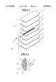
- FIG. 1 is an exploded view of an antenna, in accordance with the present invention.
- FIG. 2 is a perspective view of an asymmetric directional antenna in accordance with the present invention.
- FIG. 3 is a cross-sectional view of the antenna of FIG. 2.
- FIG. 4 is a second embodiment of the asymmetric directional antenna, in accordance with the present invention.
- FIG. 5 is an antenna having a reflector portion in accordance with the present invention.
- FIG. 6 is block diagram of a radio in accordance with the present invention.
- the present invention provides for an antenna having an antenna element embedded in a composite structure having a dielectric constant gradient.
- An antenna so constructed allows for an antenna element having a substantially shorter physical length while providing good performance.
- the antenna of the present invention is particularly useful in designs requiring a miniaturized antenna.
- the antenna can be monopole, dipole, loop, or other design, while incorporating the concepts taught herein.
- the antenna can be formed to be either symmetric or asymmetric, directional or non-directional, depending on application needs.
- an exploded perspective view of an antenna 10 is shown in accordance with the present invention.
- the antenna 10 is formed by embedding or sandwiching an antenna element 14 in a composite dielectric structure 13.
- the antenna element 14 is formed from an elongated conductor which functions both as a radiator and a collector of radio waves.
- the antenna element 14 may assume other designs.
- the antenna element 14 may include one or more conductors of varying shapes including helical, loop, or other design, depending on a particular application.
- the antenna element 14 can be embedded or otherwise attached to the dielectric structure 13 such as by plating, or by filling a preformed cavity on the dielectric structure 13, and the like.
- the dielectric structure 13 may be formed about the antenna element 14.
- the antenna 10 is fed by an integrated coaxial feedpoint 12.
- the length of an antenna can be greatly reduced by enclosing the antenna element in a high dielectric constant matrix.
- ⁇ is the relative dielectric constant.
- a radio wave traveling between interfacing media to the media interface will experience significant wave reflectivity when the dielectric constants of each of the interfacing media are mismatched, i.e., substantially different for both media.
- the degree of reflection is a function of the ratio of the respective dielectric constants. Mathematically, it can be expressed as follows:
- Coefficient of reflection ( ⁇ 1 / ⁇ 2 )-1) 2 /(( ⁇ 1 / ⁇ 2 )+1) 2 where the symbol ⁇ 1 is the dielectric constant of the first medium and ⁇ 2 is the dielectric constant of the second medium.
- the reflection is minimized by using a composite dielectric structure 13 having graduated dielectric constants.
- the composite dielectric structure 13 has a gradually decreasing dielectric constant gradient, and is implemented using multiple layers of dielectric material 15, 16, 17, 18 having a successively smaller dielectric constant.
- a layer 15 having a first dielectric constant forms the core in which the antenna element 14 is embedded.
- a second layer 16 is disposed about the first layer 15 such that the first layer 15 separates the second layer 16 from the antenna element 14.
- a third layer 17 is disposed about the second layer 15 such that the first and second layers 15, 16 separate the third layer 17 from the antenna element 14, and so on.
- the intent is to keep the dielectric constant ratio as dose to unity as possible at the interface between layers 15, 16, 17, 18 within the composite dielectric structure 13.
- the reflectivity at each interface can be reduced to approximately 0.03, using the formula for the coefficient of reflection stated above. Consequently, the total radio wave transmitted or received through the dielectric composite is the fraction passing through each interface is 0.97 (1.00-0.03) raised to the 8th power (number of interfaces), which results in approximately 78% efficiency.
- the physical size of the antenna is shrunk by a factor of 17, i.e., square root of 288 (the dielectric constant of the material enveloping the conductor).
- the dielectric composite 13 of the embodiment of FIG. 1 is constructed such that a layer of the dielectric material 15 having a high dielectric constant envelops or at least partially envelops the antenna element 14. Additionally, the successive layers of dielectric material 16, 17, 18 have successively smaller dielectric constants such that the dielectric constant of the outer layer 18 approaches that of air.
- dielectric composite 13 There are several alternatives for forming the dielectric composite 13.
- One method includes the use of low radio frequency loss ceramics.
- the dielectric composite is constructed by laminating layers of ceramic green tapes having different dielectric constants.
- Another method involves the process of dip-coating a dielectric base with different organic composite dielectrics in a layer by layer construction.
- Yet another method involves providing a two-component system, one with very high dielectric constant, and one with very low dielectric constant, and having a mixing ratio increasing or decreasing monotonically toward the conductor.
- a microscopic porosity gradient can be used within a material having a high dielectric constant, i.e., the second dielectric is air and the material becomes increasingly porous toward the preferred direction of wave propagation.
- FIG. 2 shows a asymmetrical antenna 20 in accordance with the present invention.
- FIG. 3 shows a cross-sectional view of the antenna 20 in which the dielectric composite 23 is radially disposed with respect to the antenna element 14.
- the antenna 20 is termed asymmetric because the composite dielectric structure 23 only partially envelopes the antenna element 14.
- the resultant structure also forms a directional antenna in which the preferred direction of wave propagation is defined by the composition and shape of the dielectric composite 23, and the relative positioning of the antenna element 14.
- the antenna 20 is made directional by providing for a dielectric mismatch between the dielectric composite 23 and the surrounding medium where radiation is not desired.
- the antenna 20 is formed to maximize the dielectric mismatch on one side 35 of the antenna 20, and to minimize the dielectric mismatch on the other side 36 of the antenna 20.
- the antenna element 14 is embedded in a portion 15 of the dielectric composite 23 having a high dielectric constant.
- the antenna element 14 is fully embedded within the high dielectric constant portion 15, as in the antenna 40 of FIG. 4, to maximize the effect of the dielectric mismatch. Wave propagation is impeded in the direction where material having a high dielectric constant interfaces with the surrounding medium because of the correspondingly high coefficient of reflectivity.
- the dielectric constant of the composite material 23 gradually decreases as the distance from the antenna element 14 increases, i.e., in a direction away from the antenna element 14.
- This configuration provides for a low coefficient of reflectivity at the interface between the antenna 20, 40 and the surrounding medium in such directions.
- the antenna 20, 40 is directional and the dielectric composite 23 functions as a director for directing wave propagation.
- FIG. 5 a cross-sectional view of a second embodiment of a directional antenna 50 is shown.
- This antenna 50 uses the dielectric composite 53 to form a reflector for redirecting radiated energy, and for controlling the direction of wave propagation.
- the dielectric composite 53 is constructed as before, except that the dielectric constant gradient relative to the antenna element 14 is reversed. Accordingly, the dielectric composite 53 has a gradually increasing dielectric constant gradient, i.e., the dielectric constants of the layers 18, 17, 16, 15 are successively larger, as the distance from the antenna element 14 increases, i.e., in a direction toward the antenna element 14. This results in a high coefficient of reflectivity at the interface between the outer layer 15 of the dielectric composite 53 with the surrounding medium where reflectivity is desired. However, wave propagation 52 in the direction away from the reflector through the antenna is relatively unimpeded.
- FIG. 6 is a block diagram of a radio which incorporates the antenna of the present invention.
- the radio 60 is an electronic communication device used for two-way communication, and is capable of receive and transmit operations using well known principles.
- a controller 66 uses logic and other information from an electrically coupled memory portion 68 to control the overall operation of the radio 60.
- the controller 66 is electrically coupled to an radio frequency (RF) portion 64 which includes a receiver 642, transmitter 644, and antenna switch 647.
- the RF portion 64 is electrically coupled, through the antenna switch 647, to an antenna 62 formed in accordance with the present invention (such as the antennas 10, 20, 40, 50 described above).
- RF radio frequency
- the RF portion 64 is electrically coupled, through the antenna switch 647, to an antenna 62 formed in accordance with the present invention (such as the antennas 10, 20, 40, 50 described above).
- For receive operations communication signals are received by the antenna 62 and are selectively processed by the receiver 642.
- communication signals are processed by the transceiver 644 and
- the present invention offers several advantages over the prior art.
- the composition of the dielectric structure can be selected to achieve a significant reduction in the physical length of the antenna. Additionally, the antenna can be made smaller without sacrificing good performance. Thus, the manufacture of miniaturized communication devices is greatly facilitated.
- the antenna can be formed to be either directional or non-directional, symmetrical or asymmetrical. This presents significant flexibility for a product designer.
- another aspect of the present invention provides for a wave reflector to be formed about the antenna element to allow for more control over the propagation of the radiated waves.
Abstract
Description
Claims (10)
Priority Applications (4)
| Application Number | Priority Date | Filing Date | Title |
|---|---|---|---|
| US08/251,444 US5528254A (en) | 1994-05-31 | 1994-05-31 | Antenna and method for forming same |
| JP8500896A JPH10501384A (en) | 1994-05-31 | 1995-05-12 | Antenna and its forming method |
| PCT/US1995/005906 WO1995033287A1 (en) | 1994-05-31 | 1995-05-12 | Antenna and method for forming same |
| EP95920402A EP0763265A4 (en) | 1994-05-31 | 1995-05-12 | Antenna and method for forming same |
Applications Claiming Priority (1)
| Application Number | Priority Date | Filing Date | Title |
|---|---|---|---|
| US08/251,444 US5528254A (en) | 1994-05-31 | 1994-05-31 | Antenna and method for forming same |
Publications (1)
| Publication Number | Publication Date |
|---|---|
| US5528254A true US5528254A (en) | 1996-06-18 |
Family
ID=22952003
Family Applications (1)
| Application Number | Title | Priority Date | Filing Date |
|---|---|---|---|
| US08/251,444 Expired - Lifetime US5528254A (en) | 1994-05-31 | 1994-05-31 | Antenna and method for forming same |
Country Status (4)
| Country | Link |
|---|---|
| US (1) | US5528254A (en) |
| EP (1) | EP0763265A4 (en) |
| JP (1) | JPH10501384A (en) |
| WO (1) | WO1995033287A1 (en) |
Cited By (16)
| Publication number | Priority date | Publication date | Assignee | Title |
|---|---|---|---|---|
| US5764199A (en) * | 1995-08-28 | 1998-06-09 | Datron/Transco, Inc. | Low profile semi-cylindrical lens antenna on a ground plane |
| US5781163A (en) * | 1995-08-28 | 1998-07-14 | Datron/Transco, Inc. | Low profile hemispherical lens antenna array on a ground plane |
| US5952972A (en) * | 1996-03-09 | 1999-09-14 | Her Majesty The Queen In Right Of Canada As Represented By The Minister Of Industry Through The Communications Research Centre | Broadband nonhomogeneous multi-segmented dielectric resonator antenna system |
| US6052096A (en) * | 1995-08-07 | 2000-04-18 | Murata Manufacturing Co., Ltd. | Chip antenna |
| FR2786031A1 (en) * | 1998-11-17 | 2000-05-19 | Centre Nat Rech Scient | LAMINATED DIELECTRIC REFLECTOR FOR PARABOLIC ANTENNA |
| US6133888A (en) * | 1998-11-23 | 2000-10-17 | Itt Manuafacturing Enterprises, Inc. | Polarization-agile multi-octave linear array with hemispherical field-of-view |
| FR2795240A1 (en) * | 1999-06-18 | 2000-12-22 | Nortel Matra Cellular | Base station antenna has dielectric focussing is compact and multiband |
| WO2001031746A1 (en) * | 1999-10-29 | 2001-05-03 | Antenova Limited | Steerable-beam multiple-feed dielectric resonator antenna of various cross-sections |
| US20020105479A1 (en) * | 2000-12-26 | 2002-08-08 | Hiroki Hamada | Small antenna and manufacturing method thereof |
| US6549172B1 (en) * | 1999-11-18 | 2003-04-15 | Centre National De La Recherche Scientifique (C.N.R.S.) | Antenna provided with an assembly of filtering materials |
| US6624792B1 (en) | 2002-05-16 | 2003-09-23 | Titan Systems, Corporation | Quad-ridged feed horn with two coplanar probes |
| US6914581B1 (en) * | 2001-10-31 | 2005-07-05 | Venture Partners | Focused wave antenna |
| DE102006014230A1 (en) * | 2006-03-28 | 2007-10-11 | Diehl Bgt Defence Gmbh & Co. Kg | Array of high power microwave generators for radiating high field strength pulses |
| GB2512083A (en) * | 2013-03-19 | 2014-09-24 | Jelley Lab Gmbh | Low-frequency antenna |
| WO2014148954A3 (en) * | 2013-03-19 | 2015-04-16 | Александр Метталинович ТИШИН | Low-frequency antenna |
| WO2019195758A1 (en) * | 2018-04-06 | 2019-10-10 | 3M Innovative Properties Company | Gradient permittivity film |
Families Citing this family (5)
| Publication number | Priority date | Publication date | Assignee | Title |
|---|---|---|---|---|
| JPH09275316A (en) * | 1996-04-05 | 1997-10-21 | Murata Mfg Co Ltd | Chip antenna |
| JP3737497B2 (en) * | 2003-08-25 | 2006-01-18 | オムロン株式会社 | Dielectric loaded antenna |
| JP4555830B2 (en) * | 2004-11-05 | 2010-10-06 | パイオニア株式会社 | Derivative antenna device |
| RU2484559C2 (en) * | 2010-06-08 | 2013-06-10 | Федеральное государственное автономное образовательное учреждение высшего профессионального образования "Национальный исследовательский университет "Высшая школа экономики" | Printed board with suspended substrate |
| JP6428211B2 (en) * | 2014-12-02 | 2018-11-28 | 富士通株式会社 | ANTENNA DEVICE, ANTENNA SYSTEM, AND COMMUNICATION DEVICE |
Citations (4)
| Publication number | Priority date | Publication date | Assignee | Title |
|---|---|---|---|---|
| GB1555756A (en) * | 1975-03-18 | 1979-11-14 | Aerialite Aerials Ltd | Aerials |
| US4800392A (en) * | 1987-01-08 | 1989-01-24 | Motorola, Inc. | Integral laminar antenna and radio housing |
| US5155493A (en) * | 1990-08-28 | 1992-10-13 | The United States Of America As Represented By The Secretary Of The Air Force | Tape type microstrip patch antenna |
| US5231412A (en) * | 1990-12-24 | 1993-07-27 | Motorola, Inc. | Sleeved monopole antenna |
Family Cites Families (3)
| Publication number | Priority date | Publication date | Assignee | Title |
|---|---|---|---|---|
| GB1555754A (en) * | 1975-03-18 | 1979-11-14 | Aerialite Aerials Ltd | Aerials |
| JPS5970003A (en) * | 1982-10-14 | 1984-04-20 | Koden Electronics Co Ltd | Antenna cover for ultra-short distance lader |
| IT1255602B (en) * | 1992-09-18 | 1995-11-09 | Alcatel Italia | PORTABLE LOW IRRADIANCE PORTABLE TRANSCEIVER, USING AN ANTENNA WITH ASYMMETRIC IRRADIATION DIAGRAM. |
-
1994
- 1994-05-31 US US08/251,444 patent/US5528254A/en not_active Expired - Lifetime
-
1995
- 1995-05-12 EP EP95920402A patent/EP0763265A4/en not_active Withdrawn
- 1995-05-12 JP JP8500896A patent/JPH10501384A/en active Pending
- 1995-05-12 WO PCT/US1995/005906 patent/WO1995033287A1/en not_active Application Discontinuation
Patent Citations (4)
| Publication number | Priority date | Publication date | Assignee | Title |
|---|---|---|---|---|
| GB1555756A (en) * | 1975-03-18 | 1979-11-14 | Aerialite Aerials Ltd | Aerials |
| US4800392A (en) * | 1987-01-08 | 1989-01-24 | Motorola, Inc. | Integral laminar antenna and radio housing |
| US5155493A (en) * | 1990-08-28 | 1992-10-13 | The United States Of America As Represented By The Secretary Of The Air Force | Tape type microstrip patch antenna |
| US5231412A (en) * | 1990-12-24 | 1993-07-27 | Motorola, Inc. | Sleeved monopole antenna |
Cited By (26)
| Publication number | Priority date | Publication date | Assignee | Title |
|---|---|---|---|---|
| US6052096A (en) * | 1995-08-07 | 2000-04-18 | Murata Manufacturing Co., Ltd. | Chip antenna |
| US5764199A (en) * | 1995-08-28 | 1998-06-09 | Datron/Transco, Inc. | Low profile semi-cylindrical lens antenna on a ground plane |
| US5781163A (en) * | 1995-08-28 | 1998-07-14 | Datron/Transco, Inc. | Low profile hemispherical lens antenna array on a ground plane |
| US5952972A (en) * | 1996-03-09 | 1999-09-14 | Her Majesty The Queen In Right Of Canada As Represented By The Minister Of Industry Through The Communications Research Centre | Broadband nonhomogeneous multi-segmented dielectric resonator antenna system |
| AU721740B2 (en) * | 1996-04-09 | 2000-07-13 | Communications Research Centre Of Canada | Broadband nonhomogeneous multi-segmented dielectric resonator antenna system |
| WO2000030215A1 (en) * | 1998-11-17 | 2000-05-25 | Centre National De La Recherche Scientifique (Cnrs) | Laminated dielectric reflector for parabolic antenna |
| FR2786031A1 (en) * | 1998-11-17 | 2000-05-19 | Centre Nat Rech Scient | LAMINATED DIELECTRIC REFLECTOR FOR PARABOLIC ANTENNA |
| US6133888A (en) * | 1998-11-23 | 2000-10-17 | Itt Manuafacturing Enterprises, Inc. | Polarization-agile multi-octave linear array with hemispherical field-of-view |
| FR2795240A1 (en) * | 1999-06-18 | 2000-12-22 | Nortel Matra Cellular | Base station antenna has dielectric focussing is compact and multiband |
| WO2000079643A1 (en) * | 1999-06-18 | 2000-12-28 | Nortel Matra Cellular | Radio communication base station antenna |
| US6369774B1 (en) | 1999-06-18 | 2002-04-09 | Nortel Networks S.A. | Radio communication base station antenna |
| WO2001031746A1 (en) * | 1999-10-29 | 2001-05-03 | Antenova Limited | Steerable-beam multiple-feed dielectric resonator antenna of various cross-sections |
| US6549172B1 (en) * | 1999-11-18 | 2003-04-15 | Centre National De La Recherche Scientifique (C.N.R.S.) | Antenna provided with an assembly of filtering materials |
| US20020105479A1 (en) * | 2000-12-26 | 2002-08-08 | Hiroki Hamada | Small antenna and manufacturing method thereof |
| US6917345B2 (en) * | 2000-12-26 | 2005-07-12 | The Furukawa Electric Co., Ltd. | Small antenna and manufacturing method thereof |
| US6914581B1 (en) * | 2001-10-31 | 2005-07-05 | Venture Partners | Focused wave antenna |
| US6624792B1 (en) | 2002-05-16 | 2003-09-23 | Titan Systems, Corporation | Quad-ridged feed horn with two coplanar probes |
| DE102006014230A1 (en) * | 2006-03-28 | 2007-10-11 | Diehl Bgt Defence Gmbh & Co. Kg | Array of high power microwave generators for radiating high field strength pulses |
| GB2512083A (en) * | 2013-03-19 | 2014-09-24 | Jelley Lab Gmbh | Low-frequency antenna |
| WO2014148954A3 (en) * | 2013-03-19 | 2015-04-16 | Александр Метталинович ТИШИН | Low-frequency antenna |
| GB2512083B (en) * | 2013-03-19 | 2016-10-26 | Mettalinovich Tishin Alexandr | Antenna, array or system with a material structure surrounding at least part of an antenna element |
| US10211523B2 (en) | 2013-03-19 | 2019-02-19 | Aleksandr Mettalinovich TISHIN | Low-Frequency Antenna |
| RU2562401C2 (en) * | 2013-03-20 | 2015-09-10 | Александр Метталинович Тишин | Low-frequency antenna |
| WO2019195758A1 (en) * | 2018-04-06 | 2019-10-10 | 3M Innovative Properties Company | Gradient permittivity film |
| US11637367B2 (en) | 2018-04-06 | 2023-04-25 | 3M Innovative Properties Company | Gradient permittivity film |
| US11909107B2 (en) | 2018-04-06 | 2024-02-20 | 3M Innovative Properties Company | Gradient permittivity film |
Also Published As
| Publication number | Publication date |
|---|---|
| EP0763265A1 (en) | 1997-03-19 |
| EP0763265A4 (en) | 1998-07-22 |
| WO1995033287A1 (en) | 1995-12-07 |
| JPH10501384A (en) | 1998-02-03 |
Similar Documents
| Publication | Publication Date | Title |
|---|---|---|
| US5528254A (en) | Antenna and method for forming same | |
| US11276931B2 (en) | Antenna device and antenna array | |
| US7463201B2 (en) | Aperiodic array antenna | |
| US7148850B2 (en) | Space-filling miniature antennas | |
| US7358920B2 (en) | Cavity embedded antenna | |
| US5600341A (en) | Dual function antenna structure and a portable radio having same | |
| WO2002029928A2 (en) | Slot spiral miniaturized antenna | |
| US5606332A (en) | Dual function antenna structure and a portable radio having same | |
| US5999146A (en) | Antenna device | |
| WO2020155346A1 (en) | Antenna unit, antenna system and electronic device | |
| WO2005119838A2 (en) | Nano-antenna apparatus and method | |
| JP3588445B2 (en) | Array antenna device | |
| KR20160098987A (en) | Monopole antenna | |
| EP1941579A1 (en) | Antenna device | |
| JP2004104383A (en) | Antenna device | |
| Iqbal et al. | Radiation pattern reconfigurable antenna for 5G applications | |
| Hor et al. | A Study on Gain Enhanced Leaf-Shaped Bow-Tie Slot Array Antenna within Quasi-Millimeter Wave Band | |
| JPH05191130A (en) | Three-parallel helical antenna | |
| JP2004312774A (en) | Array antenna system | |
| Kramer | Spiral antenna miniaturization with high-contrast dielectrics | |
| Babu et al. | Dual-Band MIMO Antenna Design for 5G Applications | |
| EP1699110A2 (en) | Space-filling miniature antennas | |
| JP2002217636A (en) | Dipole antenna | |
| JP2004194350A (en) | Radio equipment provided with array antenna device | |
| Mak | Reconfigurable antennas for wireless communications |
Legal Events
| Date | Code | Title | Description |
|---|---|---|---|
| AS | Assignment |
Owner name: MOTOROLA, INC., ILLINOIS Free format text: ASSIGNMENT OF ASSIGNORS INTEREST;ASSIGNORS:HOWNG, WEI-YEAN;BALZANO, QUIRINO;REEL/FRAME:007028/0192;SIGNING DATES FROM 19940520 TO 19940525 |
|
| STCF | Information on status: patent grant |
Free format text: PATENTED CASE |
|
| REMI | Maintenance fee reminder mailed | ||
| FPAY | Fee payment |
Year of fee payment: 4 |
|
| SULP | Surcharge for late payment | ||
| FPAY | Fee payment |
Year of fee payment: 8 |
|
| AS | Assignment |
Owner name: FREESCALE SEMICONDUCTOR, INC., TEXAS Free format text: ASSIGNMENT OF ASSIGNORS INTEREST;ASSIGNOR:MOTOROLA, INC.;REEL/FRAME:015698/0657 Effective date: 20040404 Owner name: FREESCALE SEMICONDUCTOR, INC.,TEXAS Free format text: ASSIGNMENT OF ASSIGNORS INTEREST;ASSIGNOR:MOTOROLA, INC.;REEL/FRAME:015698/0657 Effective date: 20040404 |
|
| AS | Assignment |
Owner name: CITIBANK, N.A. AS COLLATERAL AGENT, NEW YORK Free format text: SECURITY AGREEMENT;ASSIGNORS:FREESCALE SEMICONDUCTOR, INC.;FREESCALE ACQUISITION CORPORATION;FREESCALE ACQUISITION HOLDINGS CORP.;AND OTHERS;REEL/FRAME:018855/0129 Effective date: 20061201 Owner name: CITIBANK, N.A. AS COLLATERAL AGENT,NEW YORK Free format text: SECURITY AGREEMENT;ASSIGNORS:FREESCALE SEMICONDUCTOR, INC.;FREESCALE ACQUISITION CORPORATION;FREESCALE ACQUISITION HOLDINGS CORP.;AND OTHERS;REEL/FRAME:018855/0129 Effective date: 20061201 |
|
| FPAY | Fee payment |
Year of fee payment: 12 |
|
| AS | Assignment |
Owner name: CITIBANK, N.A., AS COLLATERAL AGENT,NEW YORK Free format text: SECURITY AGREEMENT;ASSIGNOR:FREESCALE SEMICONDUCTOR, INC.;REEL/FRAME:024397/0001 Effective date: 20100413 Owner name: CITIBANK, N.A., AS COLLATERAL AGENT, NEW YORK Free format text: SECURITY AGREEMENT;ASSIGNOR:FREESCALE SEMICONDUCTOR, INC.;REEL/FRAME:024397/0001 Effective date: 20100413 |
|
| AS | Assignment |
Owner name: ZOZO MANAGEMENT, LLC, DELAWARE Free format text: ASSIGNMENT OF ASSIGNORS INTEREST;ASSIGNOR:FREESCALE SEMICONDUCTOR, INC.;REEL/FRAME:034034/0236 Effective date: 20120814 |
|
| AS | Assignment |
Owner name: APPLE INC., CALIFORNIA Free format text: ASSIGNMENT OF ASSIGNORS INTEREST;ASSIGNOR:ZOZO MANAGEMENT, LLC;REEL/FRAME:034732/0019 Effective date: 20141219 |
|
| AS | Assignment |
Owner name: FREESCALE SEMICONDUCTOR, INC., TEXAS Free format text: PATENT RELEASE;ASSIGNOR:CITIBANK, N.A., AS COLLATERAL AGENT;REEL/FRAME:037356/0143 Effective date: 20151207 Owner name: FREESCALE SEMICONDUCTOR, INC., TEXAS Free format text: PATENT RELEASE;ASSIGNOR:CITIBANK, N.A., AS COLLATERAL AGENT;REEL/FRAME:037354/0225 Effective date: 20151207 Owner name: FREESCALE SEMICONDUCTOR, INC., TEXAS Free format text: PATENT RELEASE;ASSIGNOR:CITIBANK, N.A., AS COLLATERAL AGENT;REEL/FRAME:037356/0553 Effective date: 20151207 |