US5497156A - Towed target - Google Patents
Towed target Download PDFInfo
- Publication number
- US5497156A US5497156A US08/228,306 US22830694A US5497156A US 5497156 A US5497156 A US 5497156A US 22830694 A US22830694 A US 22830694A US 5497156 A US5497156 A US 5497156A
- Authority
- US
- United States
- Prior art keywords
- aircraft
- decoys
- decoy
- rearward
- infrared radiation
- Prior art date
- Legal status (The legal status is an assumption and is not a legal conclusion. Google has not performed a legal analysis and makes no representation as to the accuracy of the status listed.)
- Expired - Fee Related
Links
Images


Classifications
-
- H—ELECTRICITY
- H01—ELECTRIC ELEMENTS
- H01Q—ANTENNAS, i.e. RADIO AERIALS
- H01Q15/00—Devices for reflection, refraction, diffraction or polarisation of waves radiated from an antenna, e.g. quasi-optical devices
- H01Q15/14—Reflecting surfaces; Equivalent structures
-
- B—PERFORMING OPERATIONS; TRANSPORTING
- B64—AIRCRAFT; AVIATION; COSMONAUTICS
- B64D—EQUIPMENT FOR FITTING IN OR TO AIRCRAFT; FLIGHT SUITS; PARACHUTES; ARRANGEMENTS OR MOUNTING OF POWER PLANTS OR PROPULSION TRANSMISSIONS IN AIRCRAFT
- B64D3/00—Aircraft adaptations to facilitate towing or being towed
-
- H—ELECTRICITY
- H01—ELECTRIC ELEMENTS
- H01Q—ANTENNAS, i.e. RADIO AERIALS
- H01Q1/00—Details of, or arrangements associated with, antennas
- H01Q1/27—Adaptation for use in or on movable bodies
- H01Q1/28—Adaptation for use in or on aircraft, missiles, satellites, or balloons
- H01Q1/30—Means for trailing antennas
Definitions
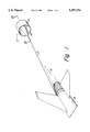
- FIG. 6 is a side view of one of the sensors and reels for deploying one of the decoys in FIG. 5.
Abstract
Description
Claims (33)
Priority Applications (1)
| Application Number | Priority Date | Filing Date | Title |
|---|---|---|---|
| US08/228,306 US5497156A (en) | 1994-04-15 | 1994-04-15 | Towed target |
Applications Claiming Priority (1)
| Application Number | Priority Date | Filing Date | Title |
|---|---|---|---|
| US08/228,306 US5497156A (en) | 1994-04-15 | 1994-04-15 | Towed target |
Publications (1)
| Publication Number | Publication Date |
|---|---|
| US5497156A true US5497156A (en) | 1996-03-05 |
Family
ID=22856625
Family Applications (1)
| Application Number | Title | Priority Date | Filing Date |
|---|---|---|---|
| US08/228,306 Expired - Fee Related US5497156A (en) | 1994-04-15 | 1994-04-15 | Towed target |
Country Status (1)
| Country | Link |
|---|---|
| US (1) | US5497156A (en) |
Cited By (24)
| Publication number | Priority date | Publication date | Assignee | Title |
|---|---|---|---|---|
| US5732289A (en) * | 1993-12-28 | 1998-03-24 | Nikon Corporation | Detecting apparatus |
| US6055909A (en) * | 1998-09-28 | 2000-05-02 | Raytheon Company | Electronically configurable towed decoy for dispensing infrared emitting flares |
| WO2001050135A2 (en) * | 1999-12-30 | 2001-07-12 | Advanced Aerospace Technologies, Inc. | Survivability and mission flexibility enhancements for reconnaissance aircraft |
| WO2003031259A2 (en) * | 2001-10-11 | 2003-04-17 | Bae Systems Information And Electronic Systems Integration Inc. | Fast deploy, retrievable and reusable airborne, counter-measure system |
| US6571714B1 (en) * | 2001-12-26 | 2003-06-03 | Meggitt Defense Systems | Silicon window infrared augmenter |
| US6683555B2 (en) * | 2001-10-11 | 2004-01-27 | Bae Systems Information And Electronic Systems Integration, Inc. | Fast deploy, retrievable and reusable airborne counter-measure system |
| US6739232B2 (en) | 2002-01-31 | 2004-05-25 | Sanmina-Sci Corporation | Towed airborne vehicle control and explosion damage assessment |
| WO2005066021A1 (en) * | 2004-01-05 | 2005-07-21 | William Moyes | Aircraft towing apparatus and method |
| US20050269456A1 (en) * | 2003-08-29 | 2005-12-08 | Smiths Aerospace, Inc. | Stabilization of a drogue body |
| US20060060691A1 (en) * | 2004-04-30 | 2006-03-23 | Burns Alan A | Self-powered tethered decoy for heat-seeking transport aircraft missile defense |
| US20060226293A1 (en) * | 2005-02-25 | 2006-10-12 | Smiths Aerospace Llc | Optical tracking system for refueling |
| US20060249009A1 (en) * | 2003-06-13 | 2006-11-09 | Rubin Eugene S | Anti-missile defense suite |
| US7154429B1 (en) * | 2004-12-06 | 2006-12-26 | Roberts Jr Charles C | Device for protecting military vehicles from infrared guided munitions |
| US7170071B1 (en) | 2004-09-29 | 2007-01-30 | Broussard Richard D | Infrared emitter |
| US20070033946A1 (en) * | 2005-08-09 | 2007-02-15 | Greene Leonard M | Helicopter defense system and method |
| US7377468B2 (en) * | 2003-08-29 | 2008-05-27 | Smiths Aerospace Llc | Active stabilization of a refueling drogue |
| US20090015458A1 (en) * | 2007-05-15 | 2009-01-15 | Eads Deutschland Gmbh | IR Jamming System For Defense Against Missiles With IR-Sensitive Homing Heads |
| US20090206198A1 (en) * | 2005-10-28 | 2009-08-20 | The Boeing Company | Aircraft engine structure-mounted aim-point biasing infrared countermeasure apparatus and method |
| US20090251353A1 (en) * | 2005-07-25 | 2009-10-08 | Heinz Bannasch | Method and Apparatus for Spoofing of Infrared, Radar and Dual-Mode Guided Missiles |
| GB2521095A (en) * | 1998-08-18 | 2015-06-17 | Daimlerchrysler Aerospace Ag | Infrared decoy and a method for deployment thereof |
| CN107618668A (en) * | 2017-08-31 | 2018-01-23 | 中国航空工业集团公司沈阳飞机设计研究所 | A kind of aviation based on wind-force damping pulls mechanism |
| US9897413B1 (en) * | 2016-07-22 | 2018-02-20 | Florida Turbine Technologies, Inc. | Process for launching a cruise missile from an aircraft |
| US10318903B2 (en) | 2016-05-06 | 2019-06-11 | General Electric Company | Constrained cash computing system to optimally schedule aircraft repair capacity with closed loop dynamic physical state and asset utilization attainment control |
| CN111981914A (en) * | 2020-08-21 | 2020-11-24 | 航天科工微电子系统研究院有限公司 | Towed bait target system based on unmanned aerial vehicle |
Citations (18)
| Publication number | Priority date | Publication date | Assignee | Title |
|---|---|---|---|---|
| US2751167A (en) * | 1954-09-02 | 1956-06-19 | Del Mar Engineering Lab Inc | Reeling apparatus for controlling a tow cable from an aircraft |
| US2823376A (en) * | 1956-05-28 | 1958-02-11 | Robert P Baldwin | Stringer radar reflective tow target |
| US2869120A (en) * | 1956-09-17 | 1959-01-13 | Del Mar Eng Lab | Tow target having combustion signal means |
| US2898588A (en) * | 1955-02-23 | 1959-08-04 | Northrop Corp | Attack deviation device |
| US3121227A (en) * | 1956-01-16 | 1964-02-11 | Dwaine R Franklin | Frangible tow target |
| US3761929A (en) * | 1971-02-24 | 1973-09-25 | Us Navy | Radar spoof |
| US3878524A (en) * | 1965-07-16 | 1975-04-15 | Dow Chemical Co | Process for preparing radar reflecting mass |
| US3976008A (en) * | 1975-02-19 | 1976-08-24 | The United States Of America As Represented By The Secretary Of The Army | Pyrotechnic seeding pellet |
| US4233605A (en) * | 1979-02-15 | 1980-11-11 | Northrop Corporation | Helicopter radar decoy |
| US4286498A (en) * | 1965-12-21 | 1981-09-01 | General Dynamics, Pomona Division | Decoy rounds and their method of fabrication |
| US4327364A (en) * | 1978-12-22 | 1982-04-27 | Rockwell International Corporation | Apparatus for converting incident microwave energy to thermal energy |
| US4718320A (en) * | 1987-01-12 | 1988-01-12 | Southwest Aerospace Corporation | Towed decoy system |
| US4756778A (en) * | 1980-12-04 | 1988-07-12 | The United States Of America As Represented By The Secretary Of The Navy | Protecting military targets against weapons having IR detectors |
| US4852455A (en) * | 1987-01-12 | 1989-08-01 | Southwest Aerospace Corporation | Decoy system |
| US5092244A (en) * | 1984-07-11 | 1992-03-03 | American Cyanamid Company | Radar- and infrared-detectable structural simulation decoy |
| US5224663A (en) * | 1991-07-01 | 1993-07-06 | Criswell David R | Vehicle propulsion system with external propellant supply |
| US5260820A (en) * | 1991-05-14 | 1993-11-09 | Bull James G | Airborne fiber optic decoy architecture |
| US5333814A (en) * | 1992-04-25 | 1994-08-02 | British Aerospace Public Limited Co. | Towed aerodynamic bodies |
-
1994
- 1994-04-15 US US08/228,306 patent/US5497156A/en not_active Expired - Fee Related
Patent Citations (18)
| Publication number | Priority date | Publication date | Assignee | Title |
|---|---|---|---|---|
| US2751167A (en) * | 1954-09-02 | 1956-06-19 | Del Mar Engineering Lab Inc | Reeling apparatus for controlling a tow cable from an aircraft |
| US2898588A (en) * | 1955-02-23 | 1959-08-04 | Northrop Corp | Attack deviation device |
| US3121227A (en) * | 1956-01-16 | 1964-02-11 | Dwaine R Franklin | Frangible tow target |
| US2823376A (en) * | 1956-05-28 | 1958-02-11 | Robert P Baldwin | Stringer radar reflective tow target |
| US2869120A (en) * | 1956-09-17 | 1959-01-13 | Del Mar Eng Lab | Tow target having combustion signal means |
| US3878524A (en) * | 1965-07-16 | 1975-04-15 | Dow Chemical Co | Process for preparing radar reflecting mass |
| US4286498A (en) * | 1965-12-21 | 1981-09-01 | General Dynamics, Pomona Division | Decoy rounds and their method of fabrication |
| US3761929A (en) * | 1971-02-24 | 1973-09-25 | Us Navy | Radar spoof |
| US3976008A (en) * | 1975-02-19 | 1976-08-24 | The United States Of America As Represented By The Secretary Of The Army | Pyrotechnic seeding pellet |
| US4327364A (en) * | 1978-12-22 | 1982-04-27 | Rockwell International Corporation | Apparatus for converting incident microwave energy to thermal energy |
| US4233605A (en) * | 1979-02-15 | 1980-11-11 | Northrop Corporation | Helicopter radar decoy |
| US4756778A (en) * | 1980-12-04 | 1988-07-12 | The United States Of America As Represented By The Secretary Of The Navy | Protecting military targets against weapons having IR detectors |
| US5092244A (en) * | 1984-07-11 | 1992-03-03 | American Cyanamid Company | Radar- and infrared-detectable structural simulation decoy |
| US4718320A (en) * | 1987-01-12 | 1988-01-12 | Southwest Aerospace Corporation | Towed decoy system |
| US4852455A (en) * | 1987-01-12 | 1989-08-01 | Southwest Aerospace Corporation | Decoy system |
| US5260820A (en) * | 1991-05-14 | 1993-11-09 | Bull James G | Airborne fiber optic decoy architecture |
| US5224663A (en) * | 1991-07-01 | 1993-07-06 | Criswell David R | Vehicle propulsion system with external propellant supply |
| US5333814A (en) * | 1992-04-25 | 1994-08-02 | British Aerospace Public Limited Co. | Towed aerodynamic bodies |
Cited By (43)
| Publication number | Priority date | Publication date | Assignee | Title |
|---|---|---|---|---|
| US5732289A (en) * | 1993-12-28 | 1998-03-24 | Nikon Corporation | Detecting apparatus |
| GB2521095A (en) * | 1998-08-18 | 2015-06-17 | Daimlerchrysler Aerospace Ag | Infrared decoy and a method for deployment thereof |
| GB2521095B (en) * | 1998-08-18 | 2016-03-23 | Daimlerchrysler Aerospace Ag | Infrared decoy and a method for deployment thereof |
| US6055909A (en) * | 1998-09-28 | 2000-05-02 | Raytheon Company | Electronically configurable towed decoy for dispensing infrared emitting flares |
| USRE46051E1 (en) | 1998-09-28 | 2016-07-05 | Raytheon Company | Electronically configurable towed decoy for dispensing infrared emitting flares, and method for dispensing flare material |
| US6705573B2 (en) | 1999-12-30 | 2004-03-16 | Advanced Aerospace Technologies, Inc. | Survivability and mission flexibility enhancements for reconnaissance aircraft |
| WO2001050135A3 (en) * | 1999-12-30 | 2001-12-20 | Advanced Aerospace Technologie | Survivability and mission flexibility enhancements for reconnaissance aircraft |
| WO2001050135A2 (en) * | 1999-12-30 | 2001-07-12 | Advanced Aerospace Technologies, Inc. | Survivability and mission flexibility enhancements for reconnaissance aircraft |
| WO2003031259A3 (en) * | 2001-10-11 | 2003-10-30 | Bae Systems Information | Fast deploy, retrievable and reusable airborne, counter-measure system |
| US6683555B2 (en) * | 2001-10-11 | 2004-01-27 | Bae Systems Information And Electronic Systems Integration, Inc. | Fast deploy, retrievable and reusable airborne counter-measure system |
| WO2003031259A2 (en) * | 2001-10-11 | 2003-04-17 | Bae Systems Information And Electronic Systems Integration Inc. | Fast deploy, retrievable and reusable airborne, counter-measure system |
| US6571714B1 (en) * | 2001-12-26 | 2003-06-03 | Meggitt Defense Systems | Silicon window infrared augmenter |
| US6739232B2 (en) | 2002-01-31 | 2004-05-25 | Sanmina-Sci Corporation | Towed airborne vehicle control and explosion damage assessment |
| US20060249009A1 (en) * | 2003-06-13 | 2006-11-09 | Rubin Eugene S | Anti-missile defense suite |
| US8066218B2 (en) * | 2003-06-13 | 2011-11-29 | Bae Systems Information And Electronic Systems Integration Inc. | Anti-missile defense suite |
| US7275718B2 (en) | 2003-08-29 | 2007-10-02 | Smiths Aerospace Llc | Active control of a drogue body |
| US20050269456A1 (en) * | 2003-08-29 | 2005-12-08 | Smiths Aerospace, Inc. | Stabilization of a drogue body |
| US7377468B2 (en) * | 2003-08-29 | 2008-05-27 | Smiths Aerospace Llc | Active stabilization of a refueling drogue |
| WO2005066021A1 (en) * | 2004-01-05 | 2005-07-21 | William Moyes | Aircraft towing apparatus and method |
| US20060060691A1 (en) * | 2004-04-30 | 2006-03-23 | Burns Alan A | Self-powered tethered decoy for heat-seeking transport aircraft missile defense |
| US7028947B2 (en) * | 2004-04-30 | 2006-04-18 | Mlho, Inc. | Self-powered tethered decoy for heat-seeking transport aircraft missile defense |
| US7170071B1 (en) | 2004-09-29 | 2007-01-30 | Broussard Richard D | Infrared emitter |
| US7154429B1 (en) * | 2004-12-06 | 2006-12-26 | Roberts Jr Charles C | Device for protecting military vehicles from infrared guided munitions |
| US20080067290A1 (en) * | 2005-02-25 | 2008-03-20 | Mickley Joseph G | Optical tracking system for airborne objects |
| US20080075467A1 (en) * | 2005-02-25 | 2008-03-27 | Smiths Aerospace Llc | Optical tracking system for airborne objects |
| US20060226293A1 (en) * | 2005-02-25 | 2006-10-12 | Smiths Aerospace Llc | Optical tracking system for refueling |
| US7681839B2 (en) | 2005-02-25 | 2010-03-23 | Smiths Aerospace Llc | Optical tracking system for refueling |
| US7686252B2 (en) * | 2005-02-25 | 2010-03-30 | Smiths Aerospace, Llc | Optical tracking system for airborne objects |
| US20100163679A1 (en) * | 2005-02-25 | 2010-07-01 | Mickley Joseph G | Optical tracking system for airborne objects |
| US8104716B2 (en) | 2005-02-25 | 2012-01-31 | Ge Aviation Systems Llc | Optical tracking system for airborne objects |
| US20090251353A1 (en) * | 2005-07-25 | 2009-10-08 | Heinz Bannasch | Method and Apparatus for Spoofing of Infrared, Radar and Dual-Mode Guided Missiles |
| US8223061B2 (en) * | 2005-07-25 | 2012-07-17 | Rheinmetall Waffe Munition Gmbh | Method and apparatus for spoofing of infrared, radar and dual-mode guided missiles |
| US20070033946A1 (en) * | 2005-08-09 | 2007-02-15 | Greene Leonard M | Helicopter defense system and method |
| US7938052B2 (en) * | 2005-10-28 | 2011-05-10 | The Boeing Company | Aircraft engine structure-mounted aim-point biasing infrared countermeasure apparatus and method |
| US20090206198A1 (en) * | 2005-10-28 | 2009-08-20 | The Boeing Company | Aircraft engine structure-mounted aim-point biasing infrared countermeasure apparatus and method |
| US8258994B2 (en) * | 2007-05-15 | 2012-09-04 | Eads Deutschland Gmbh | IR jamming system for defense against missiles with IR-sensitive homing heads |
| US20090015458A1 (en) * | 2007-05-15 | 2009-01-15 | Eads Deutschland Gmbh | IR Jamming System For Defense Against Missiles With IR-Sensitive Homing Heads |
| US10318903B2 (en) | 2016-05-06 | 2019-06-11 | General Electric Company | Constrained cash computing system to optimally schedule aircraft repair capacity with closed loop dynamic physical state and asset utilization attainment control |
| US10318904B2 (en) | 2016-05-06 | 2019-06-11 | General Electric Company | Computing system to control the use of physical state attainment of assets to meet temporal performance criteria |
| US9897413B1 (en) * | 2016-07-22 | 2018-02-20 | Florida Turbine Technologies, Inc. | Process for launching a cruise missile from an aircraft |
| CN107618668A (en) * | 2017-08-31 | 2018-01-23 | 中国航空工业集团公司沈阳飞机设计研究所 | A kind of aviation based on wind-force damping pulls mechanism |
| CN111981914A (en) * | 2020-08-21 | 2020-11-24 | 航天科工微电子系统研究院有限公司 | Towed bait target system based on unmanned aerial vehicle |
| CN111981914B (en) * | 2020-08-21 | 2022-08-02 | 航天科工微电子系统研究院有限公司 | Towed bait target system based on unmanned aerial vehicle |
Similar Documents
| Publication | Publication Date | Title |
|---|---|---|
| US5497156A (en) | Towed target | |
| US5074216A (en) | Infrared signature enhancement decoy | |
| US9074858B2 (en) | Projectile-deployed countermeasure system | |
| US10197365B1 (en) | Scalable effects net warhead | |
| US5467681A (en) | Cannon launched reconnaissance vehicle | |
| US6662700B2 (en) | Method for protecting an aircraft against a threat that utilizes an infrared sensor | |
| US5717397A (en) | Low observable shape conversion for aircraft weaponry | |
| US20220299296A1 (en) | Decoy system | |
| CN109229409A (en) | A kind of aerial rapid fire system of cluster type small drone | |
| US6012375A (en) | Aircraft infrared guided defense missile system | |
| US3866226A (en) | Radar-augmented sub-target | |
| US7943914B2 (en) | Back illumination method for counter measuring IR guided missiles | |
| US7903019B2 (en) | Protective device and protective measure for a radar system | |
| US5368255A (en) | Aerotumbling missile | |
| US5137193A (en) | Covert air-to-ground cargo recovery system | |
| US20050062638A1 (en) | Missile deflector for airplanes | |
| JP2003532589A (en) | Attack aircraft | |
| CA2012106A1 (en) | Target marber with homing head to guide projectile_ | |
| US20220097843A1 (en) | Incoming threat protection system and method of using same | |
| US8704699B2 (en) | Dipole based decoy system | |
| US4852456A (en) | Decoy system | |
| US5654522A (en) | Plume enhancement nozzle for achieving flare rotation | |
| KR102327515B1 (en) | deceit | |
| FR2712683A1 (en) | Aircraft defence weapon | |
| RU2745590C1 (en) | Method for capture of air target with a net |
Legal Events
| Date | Code | Title | Description |
|---|---|---|---|
| AS | Assignment |
Owner name: LOCKHEED CORPORATION, TEXAS Free format text: ASSIGNMENT OF ASSIGNORS INTEREST;ASSIGNOR:BUSHMAN, BOYD B.;REEL/FRAME:006972/0896 Effective date: 19940413 |
|
| AS | Assignment |
Owner name: LOCKHEED MARTIN CORPORATION, MARYLAND Free format text: MERGER;ASSIGNOR:LOCKHEED CORPORATION;REEL/FRAME:009430/0915 Effective date: 19960128 |
|
| FEPP | Fee payment procedure |
Free format text: PAYOR NUMBER ASSIGNED (ORIGINAL EVENT CODE: ASPN); ENTITY STATUS OF PATENT OWNER: LARGE ENTITY |
|
| FPAY | Fee payment |
Year of fee payment: 4 |
|
| FPAY | Fee payment |
Year of fee payment: 8 |
|
| REMI | Maintenance fee reminder mailed | ||
| LAPS | Lapse for failure to pay maintenance fees | ||
| LAPS | Lapse for failure to pay maintenance fees |
Free format text: PATENT EXPIRED FOR FAILURE TO PAY MAINTENANCE FEES (ORIGINAL EVENT CODE: EXP.); ENTITY STATUS OF PATENT OWNER: LARGE ENTITY |
|
| STCH | Information on status: patent discontinuation |
Free format text: PATENT EXPIRED DUE TO NONPAYMENT OF MAINTENANCE FEES UNDER 37 CFR 1.362 |
|
| FP | Lapsed due to failure to pay maintenance fee |
Effective date: 20080305 |