US5485630A - Audio/video distribution system - Google Patents

Audio/video distribution system Download PDF

Info

Publication number
US5485630A
US5485630A US08/221,091 US22109194A US5485630A US 5485630 A US5485630 A US 5485630A US 22109194 A US22109194 A US 22109194A US 5485630 A US5485630 A US 5485630A
Authority
US
United States
Prior art keywords
signals
link
input section
coupled
signal
Prior art date
Legal status (The legal status is an assumption and is not a legal conclusion. Google has not performed a legal analysis and makes no representation as to the accuracy of the status listed.)
Expired - Fee Related
Application number
US08/221,091
Inventor
Xiaoyang Lee
Steve Lam
Current Assignee (The listed assignees may be inaccurate. Google has not performed a legal analysis and makes no representation or warranty as to the accuracy of the list.)
Panasonic Corp of North America
Original Assignee
Panasonic Technologies Inc
Priority date (The priority date is an assumption and is not a legal conclusion. Google has not performed a legal analysis and makes no representation as to the accuracy of the date listed.)
Filing date
Publication date
Application filed by Panasonic Technologies Inc filed Critical Panasonic Technologies Inc
Priority to US08/221,091 priority Critical patent/US5485630A/en
Assigned to PANASONIC TECHNOLOGIES, INC. reassignment PANASONIC TECHNOLOGIES, INC. ASSIGNMENT OF ASSIGNORS INTEREST (SEE DOCUMENT FOR DETAILS). Assignors: LAM, STEVE, LEE, XIAOYANG
Application granted granted Critical
Publication of US5485630A publication Critical patent/US5485630A/en
Assigned to MATSUSHITA ELECTRIC CORPORATION OF AMERICA reassignment MATSUSHITA ELECTRIC CORPORATION OF AMERICA MERGER (SEE DOCUMENT FOR DETAILS). Assignors: PANASONIC TECHNOLOGIES, INC.
Anticipated expiration legal-status Critical
Expired - Fee Related legal-status Critical Current

Links

Images

Classifications

    • HELECTRICITY
    • H04ELECTRIC COMMUNICATION TECHNIQUE
    • H04HBROADCAST COMMUNICATION
    • H04H20/00Arrangements for broadcast or for distribution combined with broadcast
    • H04H20/65Arrangements characterised by transmission systems for broadcast
    • H04H20/76Wired systems
    • H04H20/77Wired systems using carrier waves
    • H04H20/78CATV [Community Antenna Television] systems
    • HELECTRICITY
    • H04ELECTRIC COMMUNICATION TECHNIQUE
    • H04HBROADCAST COMMUNICATION
    • H04H60/00Arrangements for broadcast applications with a direct linking to broadcast information or broadcast space-time; Broadcast-related systems
    • H04H60/76Arrangements characterised by transmission systems other than for broadcast, e.g. the Internet
    • H04H60/81Arrangements characterised by transmission systems other than for broadcast, e.g. the Internet characterised by the transmission system itself
    • H04H60/93Wired transmission systems
    • H04H60/95Wired transmission systems for local area
    • HELECTRICITY
    • H04ELECTRIC COMMUNICATION TECHNIQUE
    • H04HBROADCAST COMMUNICATION
    • H04H60/00Arrangements for broadcast applications with a direct linking to broadcast information or broadcast space-time; Broadcast-related systems
    • H04H60/76Arrangements characterised by transmission systems other than for broadcast, e.g. the Internet
    • H04H60/81Arrangements characterised by transmission systems other than for broadcast, e.g. the Internet characterised by the transmission system itself
    • H04H60/93Wired transmission systems
    • H04H60/96CATV systems
    • HELECTRICITY
    • H04ELECTRIC COMMUNICATION TECHNIQUE
    • H04NPICTORIAL COMMUNICATION, e.g. TELEVISION
    • H04N7/00Television systems
    • H04N7/10Adaptations for transmission by electrical cable
    • HELECTRICITY
    • H04ELECTRIC COMMUNICATION TECHNIQUE
    • H04NPICTORIAL COMMUNICATION, e.g. TELEVISION
    • H04N7/00Television systems
    • H04N7/10Adaptations for transmission by electrical cable
    • H04N7/102Circuits therefor, e.g. noise reducers, equalisers, amplifiers
    • H04N7/104Switchers or splitters

Definitions

  • This invention relates to audio/video distribution systems. More specifically, it relates to the topology and the implementation of the Node "0" of a Coaxial Bus (CXBus) network.
  • CXBus Coaxial Bus
  • the CXBus network provides the information necessary to facilitate the exchange of data and control information over the coax medium within a home.
  • the detailed description of the CXBus network may be found in the "CX Specification, IS-60.3 Coax Physical Layer and Media Specifications", revised Mar. 19, 1992, which is incorporated herein by reference for its teachings on CXBus topologies, media and devices, including Node “0" definition.
  • CXBus is also described in O'Brien Jr., "Physical and media specifications of the CXBus", IEEE Transactions on Consumer Electronics, Vol. 37, Number 3, August, 1991, which is incorporated by reference herein for its teachings on CXBus networks.
  • CEBus The Consumer Electronic Bus
  • PLBus Power Line Bus
  • TPBus Transmission-Pair Bus
  • CXBus Coaxial Bus
  • IRBus Infrared Bus
  • RFBus Radio Frequency Bus
  • FOBus Field-Optic Bus
  • CEBus comprises media with data channels and a control channel.
  • the control channel carries commands used to allocate the data channels, as well as short messages.
  • the data channels carry a variety of signals which do not fit within the bandwidth constraints of the control channel.
  • the control channel is digital, whereas the data channels may carry signals of any type.
  • the CXBus network configurations support all anticipated coax connected appliances in the home.
  • the CXBus distribution system includes a collection of coaxial cable pairs that originate at a special node distribution device called Node "0" 800, as shown in FIG. 8.
  • This dual cable approach provides sufficient spectrum space for externally generated signals from either a Cable Television (CATV) cable or Off-Air (i.e., from an outside antenna), as well as the video and audio signals generated within the home (e.g., from a video cassette recorders or surveillance cameras).
  • CATV Cable Television
  • Off-Air i.e., from an outside antenna
  • the two cables of this cable pair are described as “external” cable and "internal” cable respectively.
  • the CXBuS network may be a single independent network.
  • the CXBus network may also be interconnected with other CXBus networks or different CEBus media by using a Router, Bridge or Brouter.
  • FIG. 10 is a block diagram of a conventional Node "0" 800.
  • the CXBus network consists of one or more coaxial cable pairs attached at Node “0" 800 and terminated by a 4-way splitter/combiner 822.
  • the Node "0" 800 of FIG. 10 includes circuitry to provide the following functions:
  • An input function 802 for combining signals from Internal cable branches and for distributing signals to the internal cable branches.
  • An amplifier 812 that amplifies the block converted data channel signals 810 to drive the required number of External cable or Internal cable branches, overcoming the losses of splitters and cables to deliver the required signal strength to the distribution device.
  • a CATV/Off-Air function 814 that provides the filtering and amplification needed for distributing CATV or Off-Air television signals.
  • a control channel regenerator 816 that receives the 5.5 MHz signal, demodulates the signal, modulates a control channel signal on a 4.5 MHz channel, and provides the 4.5 MHz control channel at sufficient signal strength on all Internal cables.
  • a Node "0" device may also provide a CATV signal return path for two-way cable services as shown in FIG. 10.
  • High quality audio/video distribution is one of the important features of the CXBus network.
  • the quality of the distributed video signal in the CXBus network is heavily influenced by the following five factors:
  • S/N Signal/Noise
  • the C/N ratio (RF video carrier to noise power ratio) is one of the major parameters considered when evaluating the quality of CATV distribution system. This noise component depends on the quality of the modulators used for the internal sources. The C/N ratio may be reduced by changing the signal source. There is one noise component, however, that cannot be reduced.
  • the irreducible noise is the thermal noise. For a TV channel signal with an ideal 75 ohm impedance and 4 MHz bandwidth, the irreducible noise level is about -59 dBmV at room temperature 70° F.
  • the in-home generated audio/video signals are block converted by Node "0" 800, and the block converted signals may be fed back from the internal cable or external cable.
  • channels are allocated below 450 MHz, leaving the High band between 450 and 546 MHz open for carrying block converted signals over the external cable. This allows internally generated signals to be rebroadcast by Node "0" over the external cable.
  • Devices throughout the CXBus network may receive signals on the external cable from either the CATV or from the internal signal source (e.g., VCR without switching the devices from the external cable to the internal cable.
  • the inventors have determined that, if the nominal signal level S rec received at the device (e.g. TV) is +4 dBmV, the required output signal level from the block converter S BLOCK (considering only 4 coaxial cable pairs being driven by this Node "0" 800) is +29 dBmV.
  • the signal level 806 decreases when the number of coaxial cable pairs attached at Node “0" increases. This means that the quality of the distributed video signal 824 decreases rapidly if the size of the CXBus network expands.
  • the block converter 804 has a 4.0 dB noise figure, and only 4 coaxial cable pairs are attached at Node "0" 800, then the maximum achievable C/N ratio at the output port of the block converter 804 is worse than 36 dB even with a perfect noiseless video source and TV modulator.
  • the relation between the C/N ratio (without modulation) and the picture quality is shown in Table 1.
  • Node "0" 800 having a conventional passive input section is not practical for distributing a video signal through the CXBus network.
  • the quality of the picture from the video signals provided by Node "0" 800 is marginal at best.
  • the invention is a signal distribution subsystem adapted for use in a Node "0" device within a Coaxial Bus network.
  • the network includes a plurality of internal cables coupled to a source of up-link signals located within a first frequency band.
  • the up-link signals include audio/video signals and control channel signals.
  • the distribution subsystem comprises an active input section coupled to the plurality of internal cables.
  • the active input section individually filters and amplifies the respective up-link signals provided by the plurality of cables, and combines the up-link signals.
  • a block converter is coupled to the active input section for receiving and converting the audio-video signals from the first frequency band to a second frequency band, and for transmitting the converted signals to the active input section.
  • a control channel regenerator is coupled to the active input section for: (1) receiving the control channel signal, (2) generating a down-link control channel signal, and (3) transmitting the down-link control channel signal back through the active input section.
  • the converted signals and the down-link control channel signals are transmitted to the internal cables by the active input section.
  • FIG. 1 is a block diagram of an exemplary CXBus network including a Node "0" in accordance with the invention.
  • FIG. 2 is a block diagram of the exemplary Node "0" device shown in FIG. 1.
  • FIG. 3 is a block diagram of the input section of the Node "0" shown in FIG. 2.
  • FIG. 4 is a block diagram of the Up-link data routing section shown in FIG. 2.
  • FIG. 5 is a detailed block diagram of the Down-link data routing section shown in FIG. 2.
  • FIG. 6 is a block diagram of the control channel signal regenerator shown in FIG. 3.
  • FIG. 7 is a block diagram of the CATV/Off-Air signals interface section and the external cable distribution sections shown in FIG. 2.
  • FIG. 8 is a block diagram of the block converter shown in FIG. 2.
  • FIG. 9 is a schematic diagram of an exemplary band pass filter suitable for use in the block converter shown in FIG. 8.
  • FIG. 10 (prior art) is a block diagram of a conventional Node "0" device.
  • FIG. 1 is a block diagram of an exemplary CXBus network 11 including a Node "0" 10 in accordance with the invention.
  • FIG. 2 is a block diagram of the exemplary Node "0" device 10 shown in FIG. 1.
  • FIG. 3 is a block diagram of the input section of the Node "0" shown in FIG. 2.
  • the CXBus network 11 includes a plurality of coaxial cable pairs 20-23. Only one of the pairs 21 is shown in detail; it comprises an internal cable 21a and an external cable 21b. The remaining pairs 20, 22 and 23 are identical to pair 21a, 21b. Hereafter, the description only refers to internal cable 21a and external cable 21b. It is understood that the description of connections to the remaining cable pairs 20, 22 and 23 would be identical.
  • Each cable pair 20-23 connects the Node "0" to a respective 4-way splitter/combiner 18. Although only 4 pairs 20-23 are shown in .FIG. 1, additional pairs may be included, as described below with reference to FIGS. 2 and 3.
  • the in-home generated up-link audio/video signals are allocated in the data channel transmitting band (54 MHz-150 MHz).
  • the ULS are placed on the internal cable 21a through a tap 16.
  • the ULS are produced by devices, such as television modulator 12 or VCR 14. It is understood that there may be a variety of device types, and that the number of devices coupled to the Node "0" 10 may be large.
  • the up-link audio/video signals ULS may include a variety of data, including but not limited to:
  • the ULS signal is transmitted to the Node "0" 10, where it is block converted to the high band (450 MHz -546 MHz) or low band (324 MHz-420 MHz).
  • the block converted data channel signals (BCS) may be combined with CATV/Off-Air signals COS within Node "0" 10 and fed back to the external cable 21b. Alternatively, the BCS may be fed back to the internal cable 21a.
  • the local CATV system does not broadcast above 450 MHz (as is true for most current CATV systems in operation), it is desirable to distribute the BCS signals over the external cable 21b.
  • the network user may then watch/listen to programming from both in-home and externally generated signals transmitted over the external cable 21b, without switching the Node "0" to route the BCS over the internal cable 21a.
  • the CATV industry will broadcast signals having frequencies between 450 MHz and 1 GHz.
  • the BCS may be routed by a switch 92 (shown in FIG. 2) to the Input Sections 30 for transmission over the internal cables.
  • the BCS signals may then be transmitted back over the Internal cable 21a on the high band (450-546 MHz).
  • the control channel signals occupy reserved bandwidth between 4 MHz and 6 MHz, and use an amplitude modulated RF carrier.
  • Coax-connected devices 12 and 14 transmit an up-link control channel signal UCCS on a center frequency of 5.5 MHz and receive the retransmitted signal DCS at a center frequency of 4.5 MHz. This retransmitted control channel signal DCS is regenerated by the Node "0" 10.
  • the Node “0" 10 includes an active input section 30 (shown in FIGS. 2 and 3) coupled to the plurality of internal cables 20a-23a.
  • Input Section 30 provides a mechanism for receiving, filtering, amplifying and combining the up-link signals ULS, and for providing down-link signals.
  • the filters 32a-32d remove noise from the up-link signal ULS and prevent the block converted down-link signal DLS from being passed, with the up-link signal ULS to the block converter 90, thereby providing an additional source of noise.
  • the filtered up-link signals are amplified before they are combined, so that the C/N ratio of the signal is improved.
  • a simple resistive network 34 may be used to combine the signals from multiple channels without excessive degradation in the C/N ratio.
  • the combined signal then is passed through a second stage amplifier 36.
  • the input section 30 of Node "0" 10 provides a low insertion loss for the in-home generated audio/video signals (up-link signals, or ULS) and control channel signal.
  • Input section 30 also provides a suitable signal path for the regenerated control channel signal (DCS) and the block converted data channel signals (BCS).
  • DCS regenerated control channel signal
  • BCS block converted data channel signals
  • a Block Converter 90 is coupled to the input section 30 for receiving and converting the first audio/video signal component UDCS of the up-link signal ULS from the first frequency band to the second frequency band.
  • the Block Converter 90 provides the converted signals BCS at its output port.
  • a control channel regenerator 60 is coupled to the input section 30, The control channel regenerator performs the functions of: (1) receiving the control channel signal UCCS; (2) generating a down-link control channel signal DCS which may include the up-link control channel signal UCCS; and (3) transmitting the down-link control channel signal DCS to the input section 30,
  • the up-link signals ULS originate at a device in the building in which the Node "0" 10 is located.
  • the device may be a television modulator 12, a video cassette recorder 14, or other device that produces a wide-band output signal.
  • the up-link signals ULS are transmitted to the Input Sections block 30, where they are amplified and combined.
  • the amplified up-link signals AULS are then transmitted to an Up-link Data Routing Section 40.
  • the Up-link Data Routing Section 40 separates the amplified up-link signals AULS into up-link control channel signal UCCS and up-link data channel signals UDCS.
  • the up-link control channel signal UCCS (the 5.5 MHz signal) is transmitted into the Control Channel Regenerator 60,
  • the up-link data channel signals UDCS (which occupy the 54 MHz-150 MHz band) are fed into the Block Converter 90,
  • the Block Converter 90 relocates the up-link data channel signals to the high (450 MHz-546 MHz) band or low (324 MHz-420 MHz) band.
  • a switch 92 Two different distribution mechanisms are provided, through the use of a switch 92.
  • the switch 92 When the switch 92 is in a first position (as shown in FIG. 2), the Block Converted Output Signals BCS are provided to the External Cable Distribution Sections 80, for distribution to the devices connected to the CXBus via the external cables 20b-23b.
  • the switch 92 When the switch 92 is in a second position, the Block Converted Output Signals BCS are provided to the Down-link Data Routing Section 50 for distribution via the internal cables 20a-23a.
  • the frequency band to which the block converter 90 relocates the up-link data channel signals UDCS is determined by the choice of which external signals are connected into the home (As described with reference to FIG. 7, a switch 76 transmits either CATV or Off-Air signals at any given time).
  • a switch 76 transmits either CATV or Off-Air signals at any given time.
  • the up-link data channel signals UDCS are placed in the low band (from 324 MHz-420 MHz) by the block converter 90.
  • the up-link data channel signals UDCS are located in the high band (from 450 MHz to 546 MHz) by the block converter 90.
  • This switching of the band of frequencies used by the block converted signals between the low and high bands is desirable to avoid interference with signals in the received CATV and Off-Air signals, respectively.
  • These block converted signals BCS are fed into the External Cable Distribution Section 80.
  • the in-home generated data channel signals are combined with the signals COS coming from the CATV/Off-Air Signals Interface block 70 and distributed via the external cables 20b-23b.
  • the block converted signals BCS are to be distributed via the internal cable 20a-23a, then these data channel signals are block converted into the high (450 MHz-546 MHZ) band by the block converter 90, and the block converted signals BCS are routed to the Down-link Data Routing Section 50.
  • the block converted data channel signals BCS are combined with the down-link control channel signal DCS which is regenerated by the Control Channel Regenerator 60.
  • the down link output signals DLS from the Down-link Data Routing Section 50 are fed back to the Input Sections 30 and distributed via the internal cable 20a-23a.
  • Output signals DLS include the high band down-link data channel signals (450 MHz-546 MHz) and the control channel signal (4.5 MHz),
  • the Node "0" 10 of the exemplary embodiment of the invention has a low noise figure.
  • a noise figure as low as 5 dB may be achieved using the active input section 30 combined with directional couplers, a signal routing/distributing configuration network 40, and a control channel regenerator 60.
  • the noise figure may be maintained below 6 dB, even when more than 40 coaxial cable pairs (e.g., pairs 20, 22, 23) are attached to the Node "0" 10. This allows high quality audio/video distribution.
  • the invention provides a high quality audio/video distribution network 11, in which the quality of the distributed video signal does not depend on the number of the coaxial cable pairs attached at Node "0" 10.
  • the invention provides a high sensitivity control channel signal transceiver within control channel regenerator 60, which can receive the up link control channel signal UCCS and regenerate the down link control channel signal DCS. This regenerated control channel signal DCS is fed back into the internal cable 21a.
  • the invention allows the CXBus network 11 to be accessed directly by another network via an optional router 13 (shown in FIG. 1) via the control channel signal regenerator 60.
  • the CXBus network 11 may also be accessed directly by another medium via an optional brouter 15 (shown in FIG. 1).
  • Router 13 and Brouter 15 may also connect to the nodes (e.g., TV modulator 12) directly via additional internal cables (not shown).
  • FIG. 3 is a detailed block diagram of a single Input Section 30.
  • Node "0" 10 may include many Input Sections (not shown) identical to Input Section 30.
  • Four coaxial cables 20a-23a may be connected to each Input Section 30.
  • the Input Section 30 is connected to the internal cables 20a-23a only.
  • Each cable 38a-38d from the Input Section 30 is terminated by a 4-way splitter/combiner 18 (shown in FIG. 1).
  • Input Section 30 includes four identical branches (having elements labeled a, b, c and d, respectively), a resistive combining network 34, a pre-amplifier 36 and a passive 4-way splitter 37.
  • top branch (designated "a") in FIG. 3 is described in detail herein, it is understood that the other branches are identical. That is, items 31a-31d are identical; items 32a-32d are identical; and items 33a-33d are identical.
  • Branch "a" of the Input Section 30 includes a directional coupler 31a, a low pass filter 32a and a preamplifier 33a.
  • the impedance of the exemplary directional coupler 31a is 75 ohms, and the impedance of the exemplary pre-amplifier 33a is 50 ohms.
  • the directional coupler 31a used for branch a of the Input Section 30 has a worst case maximum pass loss (Lp) of 2 dB, a 6 dB tap loss (LT) and a 75 ohm impedance on all ports.
  • the insulation (L1) between the tap out port 38a and the output port 39a of the directional coupler 31a is about 20 dB-25 dB.
  • Conventional directional couplers manufactured by RMS are suitable for this application.
  • the low pass filter 32a has two functions. First, low pass filter 32a passes signals having frequencies below 150 MHz, and stops signals having frequencies above 450 MHz. This removes noise from the in-home generated audio/video signals ULS, and also eliminates any portion of the block converted down-link signals DLS that may be added to the Up-link signals ULS (which would saturate the Input Section 30) in directional coupler 31a. The actual insertion loss for the signals below 150 MHz is 0.6 dB and the minimum attenuation for the signals above 450 MHz is 52 dB. Secondly, the low pass filter 32a performs impedance matching between the directional coupler 31a and the preamplifier 33a.
  • each branch of the Input Section 30 passes only the control channel data and in-home generated audio/video data signals to the Up-link Data Routing Section 40. If 20 dB insulation L is assumed between the output port 39a and the tap out port 38a, then the directivity of the Input Section 30 relative to the block converted signals BCS is greater than 72 dB (when the block converted in-home generated audio/video signals BCS are fed back to the internal cable 20a, the distributed signals from the block converter are converted to occupy the high band 450 MHz-546 MHz), and the total loss for the up-link signals (5 MHz-150 MHz) is less than 3 dB.
  • the pre-amplifier 33a following the low pass filter 32a has a noise figure below 1.8 dB and a gain of more than 31 dB for signals below 200 MHz.
  • the input impedance of the pre-amplifier 33a is 50 ohms.
  • the third order intercept point is +23 dBm at 500 Mhz. This ensures that beating problems among the multiple channel subcarriers do not occur (the third order product is decreased by 3 dB for every 1 dB decrease in the input power).
  • NF T is the total noise figure of the Node "0"
  • NF1 is the noise figure of the circuitry from the input terminal of the Input Section 30 to the output terminal of the amplifiers 33a-33d (FIG. 3);
  • G1 is the gain of amplifier 33a-33d
  • NF2 is the noise figure of the circuitry between the output terminal of the amplifiers 32a-32d and the output terminal of amplifier 36;
  • G2 is the gain of amplifier 36 (FIG. 3);
  • NF3 is the noise figure of the circuitry between the output terminal of amplifier 36 and the output terminal of amplifier 93 (FIG. 8)
  • G3 is the gain of amplifier 93
  • the noise figure and the gain of the front stage 33 of Input Section 30 is the most important factor in the noise performance of the whole system.
  • the noise figure F B of each branch a-d of the Input Section 30 for the signals (5 MHz-150 MHz) is less than 4.4 dB, and each branch a-d provides more than 31 dB gain.
  • the signal level arriving at Node "0" is -4 dBmV.
  • the signal level at the output port of the pre-amplifier 33a is +24.4 dBmV.
  • a simple resistive network 34 may be used for combining the signals from the four branches a-d of the Input Section 30.
  • Other means e.g., a reactive network
  • the insertion loss of resistive network 34 is about 14 dB.
  • the signal level at the output port of the resistive combining network 34 is approximately +10 dBmV for each TV channel.
  • the combined signals from the output of the resistive combining network 34 are fed into the second amplifier stage 36.
  • the maximum possible power level at the input port of amplifier 36 is -13 dBm for 50 ohm impedance with 16 channels at +10 dBmV per channel (according to the CXBus network specification, the in-home generated audio/video signals ULS include not more than 16 television channels, so the maximum power level considered herein is the level corresponding to 16 TV channels).
  • the amplifier 36 has a noise figure of 3.6 dB, 13 dB gain for the frequency of signals less than 200 MHz, +17.5 dBm at the 1 dB compression point and +30 dBm at the third order intercept point.
  • the third order products are theoretically 90 dB below the signal carrier (the third order product is decreased by 3 dB for every 1 dB decrease of the input power).
  • the output signal level of the amplified up-link signal AULS from the amplifier 36 is about +23 dBmV for the video carrier of each TV channel signal.
  • the 14 dB loss of resistive network 34 would limit the C/N ratio, so that it would not be practical to connect the Node "0" to more than four cables.
  • the 14 dB loss of resistive network 34 would limit the C/N ratio, so that it would not be practical to connect the Node "0" to more than four cables.
  • FIG. 4 is a block diagram of the Up-link data routing section 40.
  • the +23 dBmV signal AULS provided by the Input Section block 30 is transmitted to the Up-link Data Routing Section 40.
  • N may be a number from 1 to 16.
  • the Up-link Data Routing Section 40 may be connected to 16 Input Section blocks identical to Input section block 30.
  • each input section block 30 may be coupled to four cable pairs 20-23, a total of up to 64 cable pairs may be connected to a single Node "0" 10.
  • the nominal insertion loss is 14 dB.
  • a conventional 6 dB tap out directional coupler 42 is connected to the output port of the 16-way combiner 41.
  • the directional coupler 42 is used for separating the up-link data channel signals UDCS from the up-link control channel signal UCCS.
  • a third stage amplifier 43 may be provided to boost the up-link control channel signal UCCS and transmit the amplified UCCS signal to the control channel regenerator 60 (shown in detail in FIG. 6).
  • the up-link data channel signals UDCS from the output port of the directional coupler 42 are transmitted to the Block Converter Section block 90.
  • FIG. 8 is a block diagram of the exemplary block converter 90.
  • Block Converter 90 may be a conventional block converter device. If a 3 dB noise figure is assumed for the Block Converter 90, a 20 dB gain is assumed for the front stage and a 10 dB noise figure/insertion loss is assumed for the mixer 94 (shown in FIG. 8). The total noise figure of the Node "0" is less than 5.5 dB.
  • a band pass filter 91 may be provided at the input to Block Converter Section 90.
  • An exemplary band pass filter 91 has been designed for this purpose, and is described below with reference to FIG. 9.
  • Filter 91 has an insertion loss for the 54 MHz -150 MHz band of less than 0.8 dB.
  • the attenuation for frequencies above 450 MHz is greater than 60 dB, and the frequencies below 5 MHz (e.g., the UCCS signals) have more than 45 dB attenuation.
  • the signal level at the input of the Block Converter 90 is +7 dBmV. This signal is strong enough to be converted in the Block Converter 90.
  • Band pass filter 91 attenuates and substantially filters out any of the block converted signals in the 450 to 546 MHz band that may pass back to the Up-link Data Routing Section 40.
  • the filtered signals from the band pass filter 91 are amplified in amplifier 93 and are passed through multiplier 94, which, along with oscillators 96 and 97, forms a conventional heterodyne system.
  • the 54-150 MHz signals are multiplied with the 396 or 270 MHz signals from oscillator 96 or 97, respectively, to form a signal in the high (450-546 MHz) or low (324-420 MHz) band.
  • a switch 95 selects either the low or high frequency band.
  • the up-link signals are multiplied by the 396 MHz signals from oscillator 96 to form high band signals.
  • the up-link signals are multiplied by the signals from 270 MHz oscillator 97, to form low band signals.
  • the block converted signal from multiplier 94 is provided to one of the band pass filters 99 or 100, via another switch 98.
  • the position of switches 98 and 101 is the same as the position of switch 95. That is, either all three switches 95, 98, 101 are positioned for high band signals, or all three switches are positioned for low band signals.
  • any remaining undesired signal components e.g., the 396 or 270 MHz signals, side band signals, harmonics, etc.
  • the output signals from the selected band pass filter 99 or 100 pass through a third switch 101 to a power amplifier 102.
  • the amplified signal BCS is then transmitted to either the Down-link Data Routing section 50 (shown in FIG. 2), or the External Cable Distribution Sections 80, depending on the position of switch 92.
  • FIG. 9 is a schematic diagram of an exemplary band pass filter 91 suitable for use in the block converter 90.
  • the values for the various capacitors and inductors in the exemplary band pass filter 91 of FIG. 9 are listed below in Tables 2 and 3. It is understood by one skilled in the art that other filters may be used to provide the filtering function.
  • FIG. 5 is a block diagram of the Down-Link Data Routing Section 50.
  • Down-Link Data Routing Section 50 has two input ports for receiving the block converted output signals BCS and the Down-Link Control Channel Signal DCS from the Block Converter 90 and the Control Channel Regenerator, respectively. These input signals are combined in a two way combiner 51. The combined signal from combiner 51 is then provided to an N way splitter/combiner 52, which provides the combined signals to up to 16 Input Sections 30.
  • the block converted signal level must be strong enough to overcome the signal through loss caused by the Down-link Data Routing Section 50 and the Input Sections 30.
  • the through loss for the Down-link Data Routing Section 50 is 18 dB for 16 output taps.
  • the down-link output signals DLS from the Down-link Data Routing Section 50 are transmitted to the internal cable 20a-23a through a 4-way splitter 37 and the taps 39a-39d of directional couplers 31a-31d.
  • the signal loss for the distributed signal is 13 dB.
  • the output signal level of the block converted signals BCS from the Block Converter 90 is +45 dBmV.
  • the standard output power for CATV headend equipment is +46 dBmV. This required power level may be easily achieved by using conventional CATV trunk amplifiers available from Motorola.
  • FIG. 6 is a block diagram of an exemplary Control Channel Regenerator 60 used in the Node "0" 10 shown in FIG. 2.
  • the Up-Link Control Channel Signal UCCS received by the Control Channel Regenerator 60 is passed through a 5.5 MHz band pass filter 61 to pass the 5.5 MHz control signal transmitted by devices 12 and 14 (shown in FIG. 1).
  • the 5.5 MHz signals are amplified in amplifier 62.
  • the signals received by amplifier 62 are generally sinusoidal.
  • the amplifier 62 essentially squares the signal.
  • the amplifier 62 should have sufficiently high gain so that the amplifier 62 is saturated by these signals, and the bottom and top portions of the signal are cut off. If amplifier 62 does not have sufficient gain for this purpose, an optional second amplifier 63a (shown in phantom in FIG. 6) may be added, to act as a slicer.
  • the signals are then filtered in a low pass filter 64, and are passed through a second slicer 63b to shape the signal into a square wave.
  • the demodulated output signals from the second slicer 63b are provided to a network interface 65.
  • Network interface 65 processes the UCCS signal. Also included is circuitry which passes a down-link control channel signal DCCS to the down-link Routing Section 40, as described below.
  • Network interface 65 may also include a router 13 (shown in FIG. 1) for interfacing to another network, or a brouter 15 (also shown in FIG. 1) for interfacing to another CEBus medium (e.g., IR or RF).
  • control data may also be received via network interface 65.
  • the control data are used to modulate a 4.5 MHz carrier signal to form an amplitude modulated On-Off keying R/F carrier down-link signal in node 66.
  • the amplitude modulated down-link control data signal is adjusted to a suitable signal level in attenuator 68, which also performs impedance matching.
  • the attenuated signal is filtered in band pass filter 69.
  • the filtered regenerated channel signal DCS is then transmitted to the Down-link Data Routing Section 50, where it is combined with the block converted output signal BCS, as described above with reference to FIG. 5.
  • FIG. 7 is a block diagram of the CATV/Off-Air signals interface section 70 and the external cable distribution sections 80 shown in FIG. 3.
  • the CATV/Off-Air signals interface 70 is similar to the conventional interface shown in FIG. 10.
  • the incoming CATV signals 78 are passed through a diplex filter 72a, an amplifier 74 and a tilt compensation function 73, when the input signal selection switch 76 is in a first position.
  • Tilt compensation function 73 compensates for low-frequency cable loss of 9 dB, which corresponds to 150 feet of cable.
  • a feedback loop including diplex filter 72c and amplifier 72b is provided. If the input signal selection switch 76 is in the second position (not shown), the Off-Air signals are used.
  • the Off-Air signals 79 are passed through a 324 MHz-420 MHz notch filter, and are then passed through amplifier 74, and tilt compensation 73.
  • a directional coupler 71 receives the signals from the tilt compensation function 73 or from the Block Converter 90, and provides the received signals to a further directional coupler 77.
  • Directional Coupler 77 combines the CATV signal 79 and one of the Block Converted Down-link Signals BCS or Off-Air signals from tilt compensation function 73, and transmits the combined signals to the External Cable Distribution Sections 80.
  • the External Cable Distribution Sections 80 include an N way splitter 82, where N may be a number from 1 to 16. Each of the output ports of the splitter 82 is coupled to a four way splitter 83, so that up to 64 external cables may be accommodated.
  • the total noise figure for the exemplary Node “0" 10 is less than 5.5 dB with the ability to drive up to 64 coaxial cable pairs. This means that Node “0" 10 may operate with 256 coaxial attached devices when each cable e.g., 20a is terminated by a 4-way splitter/combiner 18 (shown in FIG. 1). Because the low noise figure and high gain are achieved in the Input Section 30 of the Node "0" 10, the total noise figure of the node “0" 10 does not degrade if the number of coaxial cable pair attached to the Node "0" 10 is increased. Exemplary Node "0" 10 makes a high quality in-home audio/video distribution network 11 achievable.

Abstract

A Node "0" device for a Consumer Electronics Coaxial Bus (CXBUS) network is provided. The network has a plurality of internal cables coupled to a source of up-link signals located within a first frequency band. The up-link signals include first audio/video (A/V) signals (which may be digital or analog) and control signals. External cables provide second A/V signals located within a second frequency band. An active input section is coupled to the internal cables. The input section individually filters and amplifies the up-link signals and combines the amplified signals. The input section provides a down-link signal path. A block converter coupled to the input section converts the first A/V signal from the first frequency band to the second frequency band, and provides the converted signals at its output port. A control channel regenerator coupled to the input section receives the control signal, generates a down-link control signal, and transmits the down-link control signal to the input section. An external cable distribution section is coupled to the external cables and to the source of second A/V signals. The external cable distribution section receives either the converted signals, the second A/V signals or both, and transmits the received signals to the external cables.

Description

FIELD OF THE INVENTION
This invention relates to audio/video distribution systems. More specifically, it relates to the topology and the implementation of the Node "0" of a Coaxial Bus (CXBus) network.
BACKGROUND OF THE INVENTION
The CXBus network provides the information necessary to facilitate the exchange of data and control information over the coax medium within a home. The detailed description of the CXBus network may be found in the "CX Specification, IS-60.3 Coax Physical Layer and Media Specifications", revised Mar. 19, 1992, which is incorporated herein by reference for its teachings on CXBus topologies, media and devices, including Node "0" definition. CXBus is also described in O'Brien Jr., "Physical and media specifications of the CXBus", IEEE Transactions on Consumer Electronics, Vol. 37, Number 3, August, 1991, which is incorporated by reference herein for its teachings on CXBus networks. A publication by J. Hofmann entitled "The Consumer Electronic Bus: an Integrated Multi-Media LAN for the Home", International Journal of Digital and Analog Communication Systems, Vol. 4, 77-86, (1991), (which is incorporated herein by reference for its teachings on CEBus network architectures) describes issues related to frequency placement of block converted signals.
The Consumer Electronic Bus (CEBus) is a multimedia LAN standard for use by the Electronics Industry Association's Consumer Electronics Bus Committee. CEBus provides a standard communications interface to each of six different media. These media include: PLBus (Power Line Bus), TPBus (Twisted-Pair Bus), CXBus (Coaxial Bus), IRBus (Infrared Bus), RFBus (Radio Frequency Bus) and FOBus (Fiber-Optic Bus). CEBus comprises media with data channels and a control channel. The control channel carries commands used to allocate the data channels, as well as short messages. The data channels carry a variety of signals which do not fit within the bandwidth constraints of the control channel. The control channel is digital, whereas the data channels may carry signals of any type.
CXBus network configurations support all anticipated coax connected appliances in the home. The CXBus distribution system includes a collection of coaxial cable pairs that originate at a special node distribution device called Node "0" 800, as shown in FIG. 8. This dual cable approach provides sufficient spectrum space for externally generated signals from either a Cable Television (CATV) cable or Off-Air (i.e., from an outside antenna), as well as the video and audio signals generated within the home (e.g., from a video cassette recorders or surveillance cameras). The two cables of this cable pair are described as "external" cable and "internal" cable respectively.
The CXBuS network may be a single independent network. The CXBus network may also be interconnected with other CXBus networks or different CEBus media by using a Router, Bridge or Brouter.
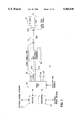
FIG. 10 is a block diagram of a conventional Node "0" 800. The CXBus network consists of one or more coaxial cable pairs attached at Node "0" 800 and terminated by a 4-way splitter/combiner 822. The Node "0" 800 of FIG. 10 includes circuitry to provide the following functions:
1. An input function 802 for combining signals from Internal cable branches and for distributing signals to the internal cable branches.
2. A block converter 804 for block frequency conversion of data channel signals 806 for distribution back onto the Internal cable (not shown) via input function 802 or External cable (not shown) via external cable output function 808.
3. An amplifier 812 that amplifies the block converted data channel signals 810 to drive the required number of External cable or Internal cable branches, overcoming the losses of splitters and cables to deliver the required signal strength to the distribution device.
4. A CATV/Off-Air function 814 that provides the filtering and amplification needed for distributing CATV or Off-Air television signals.
5. A control channel regenerator 816 that receives the 5.5 MHz signal, demodulates the signal, modulates a control channel signal on a 4.5 MHz channel, and provides the 4.5 MHz control channel at sufficient signal strength on all Internal cables.
6. A Node "0" device may also provide a CATV signal return path for two-way cable services as shown in FIG. 10.
High quality audio/video distribution is one of the important features of the CXBus network. The quality of the distributed video signal in the CXBus network is heavily influenced by the following five factors:
1. The Signal/Noise (S/N) ratio of the video source which is used in the network;
2. the Carrier/Noise (C/N) ratio of the output signal from any modulator which generates signals to be distributed on the CXBus;
3. the signal level that is allowed to be placed on the network;
4. the topology of the CXBus network; and
5. the noise figure of the Node "0".
The C/N ratio (RF video carrier to noise power ratio) is one of the major parameters considered when evaluating the quality of CATV distribution system. This noise component depends on the quality of the modulators used for the internal sources. The C/N ratio may be reduced by changing the signal source. There is one noise component, however, that cannot be reduced. The irreducible noise is the thermal noise. For a TV channel signal with an ideal 75 ohm impedance and 4 MHz bandwidth, the irreducible noise level is about -59 dBmV at room temperature 70° F.
For the CXBus network, the in-home generated audio/video signals are block converted by Node "0" 800, and the block converted signals may be fed back from the internal cable or external cable.
In most current cable systems, channels are allocated below 450 MHz, leaving the High band between 450 and 546 MHz open for carrying block converted signals over the external cable. This allows internally generated signals to be rebroadcast by Node "0" over the external cable. Devices throughout the CXBus network may receive signals on the external cable from either the CATV or from the internal signal source (e.g., VCR without switching the devices from the external cable to the internal cable.
The inventors have determined that, if the nominal signal level Srec received at the device (e.g. TV) is +4 dBmV, the required output signal level from the block converter SBLOCK (considering only 4 coaxial cable pairs being driven by this Node "0" 800) is +29 dBmV.
When the block converted signals 810 are fed back to the internal cable input section 802, this +29 dBmV signal leaks into the input of the block converter 804 through the 2-way splitter/combiner 818 and becomes extra noise relative to the signal 806 coming from the device sources (e.g., a Video Cassette Recorder, VCR). It is necessary to add an additional band pass filter 820 in front of the block converter 804, but this causes additional signal loss, lowering the C/N ratio.
Because the passive splitter/combiner 822 is used at the input 802 of the Node "0" 800, the signal level 806 decreases when the number of coaxial cable pairs attached at Node "0" increases. This means that the quality of the distributed video signal 824 decreases rapidly if the size of the CXBus network expands.
Based on the above design considerations, if the block converter 804 has a 4.0 dB noise figure, and only 4 coaxial cable pairs are attached at Node "0" 800, then the maximum achievable C/N ratio at the output port of the block converter 804 is worse than 36 dB even with a perfect noiseless video source and TV modulator. The relation between the C/N ratio (without modulation) and the picture quality is shown in Table 1.
              TABLE 1                                                     
______________________________________                                    
C/N Ratio (dB)   Picture Quality                                          
______________________________________                                    
over 42 dB       Excellent                                                
40 dB-42 dB      Good-Excellent                                           
38 dB-40 dB      Fair-Good                                                
36 dB-38 dB      Passable-Fair                                            
34 dB-36 dB      Objectionable-Passable                                   
under 34 dB      Unusable                                                 
______________________________________                                    
Based on table 1, a Node "0" 800 having a conventional passive input section is not practical for distributing a video signal through the CXBus network. The quality of the picture from the video signals provided by Node "0" 800 is marginal at best.
In order to provide a CXBus network that is able to distribute high quality audio/video signals, a very low noise figure for Node "0" is desired.
SUMMARY OF THE INVENTION
The invention is a signal distribution subsystem adapted for use in a Node "0" device within a Coaxial Bus network. The network includes a plurality of internal cables coupled to a source of up-link signals located within a first frequency band. The up-link signals include audio/video signals and control channel signals.
The distribution subsystem comprises an active input section coupled to the plurality of internal cables. The active input section individually filters and amplifies the respective up-link signals provided by the plurality of cables, and combines the up-link signals.
A block converter is coupled to the active input section for receiving and converting the audio-video signals from the first frequency band to a second frequency band, and for transmitting the converted signals to the active input section.
A control channel regenerator is coupled to the active input section for: (1) receiving the control channel signal, (2) generating a down-link control channel signal, and (3) transmitting the down-link control channel signal back through the active input section. The converted signals and the down-link control channel signals are transmitted to the internal cables by the active input section.
BRIEF DESCRIPTION OF THE DRAWINGS
FIG. 1 is a block diagram of an exemplary CXBus network including a Node "0" in accordance with the invention.
FIG. 2 is a block diagram of the exemplary Node "0" device shown in FIG. 1.
FIG. 3 is a block diagram of the input section of the Node "0" shown in FIG. 2.
FIG. 4 is a block diagram of the Up-link data routing section shown in FIG. 2.
FIG. 5 is a detailed block diagram of the Down-link data routing section shown in FIG. 2.
FIG. 6 is a block diagram of the control channel signal regenerator shown in FIG. 3.
FIG. 7 is a block diagram of the CATV/Off-Air signals interface section and the external cable distribution sections shown in FIG. 2.
FIG. 8 is a block diagram of the block converter shown in FIG. 2.
FIG. 9 is a schematic diagram of an exemplary band pass filter suitable for use in the block converter shown in FIG. 8.
FIG. 10 (prior art) is a block diagram of a conventional Node "0" device.
OVERVIEW
Reference is first made to FIGS. 1-3. FIG. 1 is a block diagram of an exemplary CXBus network 11 including a Node "0" 10 in accordance with the invention. FIG. 2 is a block diagram of the exemplary Node "0" device 10 shown in FIG. 1. FIG. 3 is a block diagram of the input section of the Node "0" shown in FIG. 2.
The following two terms are defined herein as follows:
Up-link--The link from a device, such as device 12 to Node "0" 10.
Down-link--The link from Node "0" 10 to a device, such as device 12.
Referring to FIG. 1, the CXBus network 11 includes a plurality of coaxial cable pairs 20-23. Only one of the pairs 21 is shown in detail; it comprises an internal cable 21a and an external cable 21b. The remaining pairs 20, 22 and 23 are identical to pair 21a, 21b. Hereafter, the description only refers to internal cable 21a and external cable 21b. It is understood that the description of connections to the remaining cable pairs 20, 22 and 23 would be identical. Each cable pair 20-23 connects the Node "0" to a respective 4-way splitter/combiner 18. Although only 4 pairs 20-23 are shown in .FIG. 1, additional pairs may be included, as described below with reference to FIGS. 2 and 3.
The in-home generated up-link audio/video signals (ULS) are allocated in the data channel transmitting band (54 MHz-150 MHz). The ULS are placed on the internal cable 21a through a tap 16. The ULS are produced by devices, such as television modulator 12 or VCR 14. It is understood that there may be a variety of device types, and that the number of devices coupled to the Node "0" 10 may be large. The up-link audio/video signals ULS may include a variety of data, including but not limited to:
1. Audio/video programs;
2. Video menu information distributed to a plurality of terminals within the home;
3. Displays from interactive multi-media programs;
4. Video signals from surveillance cameras; and
5. Voice Signals.
The ULS signal is transmitted to the Node "0" 10, where it is block converted to the high band (450 MHz -546 MHz) or low band (324 MHz-420 MHz). The block converted data channel signals (BCS) may be combined with CATV/Off-Air signals COS within Node "0" 10 and fed back to the external cable 21b. Alternatively, the BCS may be fed back to the internal cable 21a.
If the local CATV system does not broadcast above 450 MHz (as is true for most current CATV systems in operation), it is desirable to distribute the BCS signals over the external cable 21b. The network user may then watch/listen to programming from both in-home and externally generated signals transmitted over the external cable 21b, without switching the Node "0" to route the BCS over the internal cable 21a.
If the CATV signal is placed on the CXBus network 11, block converted data channel signals BCS in the high band (450 MHz-546 MHz) are combined with the CATV signals and fed back to external cable 21b. If the Off-Air signal is placed on the CXBus network 11 BCS signals in the low band (324 MHz-420 MHz) are combined with the Off-Air signals and fed back to the external cable 21b.
In the future, it is contemplated that the CATV industry will broadcast signals having frequencies between 450 MHz and 1 GHz. To. accommodate the presence of these additional external signals, the BCS may be routed by a switch 92 (shown in FIG. 2) to the Input Sections 30 for transmission over the internal cables. The BCS signals may then be transmitted back over the Internal cable 21a on the high band (450-546 MHz).
The control channel signals occupy reserved bandwidth between 4 MHz and 6 MHz, and use an amplitude modulated RF carrier. Coax-connected devices 12 and 14 transmit an up-link control channel signal UCCS on a center frequency of 5.5 MHz and receive the retransmitted signal DCS at a center frequency of 4.5 MHz. This retransmitted control channel signal DCS is regenerated by the Node "0" 10.
According to the invention, the Node "0" 10 includes an active input section 30 (shown in FIGS. 2 and 3) coupled to the plurality of internal cables 20a-23a. Input Section 30 provides a mechanism for receiving, filtering, amplifying and combining the up-link signals ULS, and for providing down-link signals. As described below with reference to FIG. 3, the filters 32a-32d remove noise from the up-link signal ULS and prevent the block converted down-link signal DLS from being passed, with the up-link signal ULS to the block converter 90, thereby providing an additional source of noise. The filtered up-link signals are amplified before they are combined, so that the C/N ratio of the signal is improved. Once the filtered signal is amplified in a first amplifier stage 33 (having high gain and low noise figure), a simple resistive network 34 may be used to combine the signals from multiple channels without excessive degradation in the C/N ratio. The combined signal then is passed through a second stage amplifier 36.
According to another aspect of the invention, the input section 30 of Node "0" 10 provides a low insertion loss for the in-home generated audio/video signals (up-link signals, or ULS) and control channel signal. Input section 30 also provides a suitable signal path for the regenerated control channel signal (DCS) and the block converted data channel signals (BCS).
Referring now to FIG. 2, a Block Converter 90 is coupled to the input section 30 for receiving and converting the first audio/video signal component UDCS of the up-link signal ULS from the first frequency band to the second frequency band. The Block Converter 90 provides the converted signals BCS at its output port.
A control channel regenerator 60 is coupled to the input section 30, The control channel regenerator performs the functions of: (1) receiving the control channel signal UCCS; (2) generating a down-link control channel signal DCS which may include the up-link control channel signal UCCS; and (3) transmitting the down-link control channel signal DCS to the input section 30,
The up-link signals ULS originate at a device in the building in which the Node "0" 10 is located. The device may be a television modulator 12, a video cassette recorder 14, or other device that produces a wide-band output signal. The up-link signals ULS are transmitted to the Input Sections block 30, where they are amplified and combined. The amplified up-link signals AULS are then transmitted to an Up-link Data Routing Section 40. The Up-link Data Routing Section 40 separates the amplified up-link signals AULS into up-link control channel signal UCCS and up-link data channel signals UDCS.
The up-link control channel signal UCCS (the 5.5 MHz signal) is transmitted into the Control Channel Regenerator 60, The up-link data channel signals UDCS (which occupy the 54 MHz-150 MHz band) are fed into the Block Converter 90, The Block Converter 90 relocates the up-link data channel signals to the high (450 MHz-546 MHz) band or low (324 MHz-420 MHz) band.
Two different distribution mechanisms are provided, through the use of a switch 92. When the switch 92 is in a first position (as shown in FIG. 2), the Block Converted Output Signals BCS are provided to the External Cable Distribution Sections 80, for distribution to the devices connected to the CXBus via the external cables 20b-23b. When the switch 92 is in a second position, the Block Converted Output Signals BCS are provided to the Down-link Data Routing Section 50 for distribution via the internal cables 20a-23a.
First, if the in-home generated data channel signals are to be distributed via the external cable 20b-23b, then the frequency band to which the block converter 90 relocates the up-link data channel signals UDCS is determined by the choice of which external signals are connected into the home (As described with reference to FIG. 7, a switch 76 transmits either CATV or Off-Air signals at any given time). Referring again to FIG. 2, if Off-Air signals are being transmitted into the home, the up-link data channel signals UDCS are placed in the low band (from 324 MHz-420 MHz) by the block converter 90. If CATV signals are being-transmitted, the up-link data channel signals UDCS are located in the high band (from 450 MHz to 546 MHz) by the block converter 90. This switching of the band of frequencies used by the block converted signals between the low and high bands is desirable to avoid interference with signals in the received CATV and Off-Air signals, respectively. These block converted signals BCS are fed into the External Cable Distribution Section 80. In the External Cable Distribution Section 80, the in-home generated data channel signals are combined with the signals COS coming from the CATV/Off-Air Signals Interface block 70 and distributed via the external cables 20b-23b.
Secondly, if the block converted signals BCS are to be distributed via the internal cable 20a-23a, then these data channel signals are block converted into the high (450 MHz-546 MHZ) band by the block converter 90, and the block converted signals BCS are routed to the Down-link Data Routing Section 50. In the Down-link Data Routing Section 50, the block converted data channel signals BCS are combined with the down-link control channel signal DCS which is regenerated by the Control Channel Regenerator 60. The down link output signals DLS from the Down-link Data Routing Section 50, are fed back to the Input Sections 30 and distributed via the internal cable 20a-23a. Output signals DLS include the high band down-link data channel signals (450 MHz-546 MHz) and the control channel signal (4.5 MHz),
The Node "0" 10 of the exemplary embodiment of the invention has a low noise figure. A noise figure as low as 5 dB may be achieved using the active input section 30 combined with directional couplers, a signal routing/distributing configuration network 40, and a control channel regenerator 60. The noise figure may be maintained below 6 dB, even when more than 40 coaxial cable pairs (e.g., pairs 20, 22, 23) are attached to the Node "0" 10. This allows high quality audio/video distribution.
The invention provides a high quality audio/video distribution network 11, in which the quality of the distributed video signal does not depend on the number of the coaxial cable pairs attached at Node "0" 10.
The invention provides a high sensitivity control channel signal transceiver within control channel regenerator 60, which can receive the up link control channel signal UCCS and regenerate the down link control channel signal DCS. This regenerated control channel signal DCS is fed back into the internal cable 21a.
The invention allows the CXBus network 11 to be accessed directly by another network via an optional router 13 (shown in FIG. 1) via the control channel signal regenerator 60. The CXBus network 11 may also be accessed directly by another medium via an optional brouter 15 (shown in FIG. 1). Router 13 and Brouter 15 may also connect to the nodes (e.g., TV modulator 12) directly via additional internal cables (not shown).
DETAILED DESCRIPTION OF THE INVENTION
As described with reference to FIGS. 1 and 2, the up-link signals ULS pass through the Input Sections 30 first. FIG. 3 is a detailed block diagram of a single Input Section 30. Depending on the number of devices, Node "0" 10 may include many Input Sections (not shown) identical to Input Section 30. Four coaxial cables 20a-23a may be connected to each Input Section 30. The Input Section 30 is connected to the internal cables 20a-23a only. Each cable 38a-38d from the Input Section 30 is terminated by a 4-way splitter/combiner 18 (shown in FIG. 1). As shown in FIG. 3, Input Section 30 includes four identical branches (having elements labeled a, b, c and d, respectively), a resistive combining network 34, a pre-amplifier 36 and a passive 4-way splitter 37.
Although only the top branch (designated "a") in FIG. 3 is described in detail herein, it is understood that the other branches are identical. That is, items 31a-31d are identical; items 32a-32d are identical; and items 33a-33d are identical.
Branch "a" of the Input Section 30 includes a directional coupler 31a, a low pass filter 32a and a preamplifier 33a. The impedance of the exemplary directional coupler 31a is 75 ohms, and the impedance of the exemplary pre-amplifier 33a is 50 ohms. The directional coupler 31a used for branch a of the Input Section 30 has a worst case maximum pass loss (Lp) of 2 dB, a 6 dB tap loss (LT) and a 75 ohm impedance on all ports. The insulation (L1) between the tap out port 38a and the output port 39a of the directional coupler 31a is about 20 dB-25 dB. Conventional directional couplers manufactured by RMS are suitable for this application.
The low pass filter 32a has two functions. First, low pass filter 32a passes signals having frequencies below 150 MHz, and stops signals having frequencies above 450 MHz. This removes noise from the in-home generated audio/video signals ULS, and also eliminates any portion of the block converted down-link signals DLS that may be added to the Up-link signals ULS (which would saturate the Input Section 30) in directional coupler 31a. The actual insertion loss for the signals below 150 MHz is 0.6 dB and the minimum attenuation for the signals above 450 MHz is 52 dB. Secondly, the low pass filter 32a performs impedance matching between the directional coupler 31a and the preamplifier 33a.
By combining the directional coupler 31a and the low pass filter 32a, each branch of the Input Section 30 passes only the control channel data and in-home generated audio/video data signals to the Up-link Data Routing Section 40. If 20 dB insulation L is assumed between the output port 39a and the tap out port 38a, then the directivity of the Input Section 30 relative to the block converted signals BCS is greater than 72 dB (when the block converted in-home generated audio/video signals BCS are fed back to the internal cable 20a, the distributed signals from the block converter are converted to occupy the high band 450 MHz-546 MHz), and the total loss for the up-link signals (5 MHz-150 MHz) is less than 3 dB.
The pre-amplifier 33a following the low pass filter 32a has a noise figure below 1.8 dB and a gain of more than 31 dB for signals below 200 MHz. The input impedance of the pre-amplifier 33a is 50 ohms. The third order intercept point is +23 dBm at 500 Mhz. This ensures that beating problems among the multiple channel subcarriers do not occur (the third order product is decreased by 3 dB for every 1 dB decrease in the input power).
The equation used for calculating the noise figure is 10 log (NFT), where NFT is:
NF.sub.T =NF.sub.1 +(NF.sub.2 -1)/G.sub.1 +(NF.sub.3 -1)/(G.sub.1 G.sub.2)+. . . +(NF.sub.n -1)/(G.sub.1 G.sub.2. . . G.sub.n-1) (1)
Where: NFT is the total noise figure of the Node "0";
NF1 is the noise figure of the circuitry from the input terminal of the Input Section 30 to the output terminal of the amplifiers 33a-33d (FIG. 3);
G1 is the gain of amplifier 33a-33d;
NF2 is the noise figure of the circuitry between the output terminal of the amplifiers 32a-32d and the output terminal of amplifier 36;
G2 is the gain of amplifier 36 (FIG. 3);
NF3 is the noise figure of the circuitry between the output terminal of amplifier 36 and the output terminal of amplifier 93 (FIG. 8)
G3 is the gain of amplifier 93
From equation (1), the noise figure and the gain of the front stage 33 of Input Section 30 is the most important factor in the noise performance of the whole system. The noise figure FB of each branch a-d of the Input Section 30 for the signals (5 MHz-150 MHz) is less than 4.4 dB, and each branch a-d provides more than 31 dB gain. For the CXBus network 11 shown in FIG. 1, if the output signal level from the TV modulator is +6 dBmV and the total cable loss between the modulator 12 and Node "0" 10 is 3 dB, then the signal level arriving at Node "0" is -4 dBmV. When the signal level arriving at the Node "0" 10 is -4 dBmV, the signal level at the output port of the pre-amplifier 33a is +24.4 dBmV.
As shown in FIG. 3, a simple resistive network 34 may be used for combining the signals from the four branches a-d of the Input Section 30. Other means (e.g., a reactive network) may also be used for combining the signals. The insertion loss of resistive network 34 is about 14 dB. The signal level at the output port of the resistive combining network 34 is approximately +10 dBmV for each TV channel. The combined signals from the output of the resistive combining network 34 are fed into the second amplifier stage 36. The maximum possible power level at the input port of amplifier 36 is -13 dBm for 50 ohm impedance with 16 channels at +10 dBmV per channel (according to the CXBus network specification, the in-home generated audio/video signals ULS include not more than 16 television channels, so the maximum power level considered herein is the level corresponding to 16 TV channels).
The amplifier 36 has a noise figure of 3.6 dB, 13 dB gain for the frequency of signals less than 200 MHz, +17.5 dBm at the 1 dB compression point and +30 dBm at the third order intercept point. In the output signals of amplifier 36, the third order products are theoretically 90 dB below the signal carrier (the third order product is decreased by 3 dB for every 1 dB decrease of the input power). The output signal level of the amplified up-link signal AULS from the amplifier 36 is about +23 dBmV for the video carrier of each TV channel signal.
Without the first pre-amplifying stage 33 of the present invention, the 14 dB loss of resistive network 34 would limit the C/N ratio, so that it would not be practical to connect the Node "0" to more than four cables. By amplifying the signals in preamplifiers 33a-33d according to the invention, a much larger number of cables may be connected with good picture quality. Additionally, a simple and inexpensive resistive network 34 becomes possible when preamplifiers 33a-33d are used.
FIG. 4 is a block diagram of the Up-link data routing section 40. The +23 dBmV signal AULS provided by the Input Section block 30 is transmitted to the Up-link Data Routing Section 40. At the input of the Up-link Data Routing Section 40 is a passive N-way power combiner 41, where N may be a number from 1 to 16. Thus, the Up-link Data Routing Section 40 may be connected to 16 Input Section blocks identical to Input section block 30. Furthermore, because each input section block 30 may be coupled to four cable pairs 20-23, a total of up to 64 cable pairs may be connected to a single Node "0" 10. For a conventional 16-way power combiner 41, the nominal insertion loss is 14 dB. A conventional 6 dB tap out directional coupler 42 is connected to the output port of the 16-way combiner 41. The directional coupler 42 is used for separating the up-link data channel signals UDCS from the up-link control channel signal UCCS. Optionally, a third stage amplifier 43 may be provided to boost the up-link control channel signal UCCS and transmit the amplified UCCS signal to the control channel regenerator 60 (shown in detail in FIG. 6).
From equation (1) above, so long as the first stage pre-amplifiers 33a-33d of Input Section 30 (shown in FIG. 3) have high gain and a low noise figure, then the noise figures of the third stage amplifier 43 (FIG. 4) is not critical to the determination of the total noise figure NFT. The third stage noise figure effects are decreased by the product of the gains of other stages in front of it. The same is true for further (fourth, etc.) amplifier stages. Thus, in an alternate embodiment, directional coupler 42 in the Up-link Data Routing Section 40 may be replaced by a 2-way splitter (not shown), without substantially impairing the quality of the audio/video signals.
The up-link data channel signals UDCS from the output port of the directional coupler 42 are transmitted to the Block Converter Section block 90.
FIG. 8 is a block diagram of the exemplary block converter 90. Block Converter 90 may be a conventional block converter device. If a 3 dB noise figure is assumed for the Block Converter 90, a 20 dB gain is assumed for the front stage and a 10 dB noise figure/insertion loss is assumed for the mixer 94 (shown in FIG. 8). The total noise figure of the Node "0" is less than 5.5 dB.
A band pass filter 91 may be provided at the input to Block Converter Section 90. An exemplary band pass filter 91 has been designed for this purpose, and is described below with reference to FIG. 9.
Filter 91 has an insertion loss for the 54 MHz -150 MHz band of less than 0.8 dB. The attenuation for frequencies above 450 MHz is greater than 60 dB, and the frequencies below 5 MHz (e.g., the UCCS signals) have more than 45 dB attenuation. Using filter 91, the signal level at the input of the Block Converter 90 is +7 dBmV. This signal is strong enough to be converted in the Block Converter 90. Band pass filter 91 attenuates and substantially filters out any of the block converted signals in the 450 to 546 MHz band that may pass back to the Up-link Data Routing Section 40.
The filtered signals from the band pass filter 91 are amplified in amplifier 93 and are passed through multiplier 94, which, along with oscillators 96 and 97, forms a conventional heterodyne system. The 54-150 MHz signals are multiplied with the 396 or 270 MHz signals from oscillator 96 or 97, respectively, to form a signal in the high (450-546 MHz) or low (324-420 MHz) band. A switch 95 selects either the low or high frequency band. For CATV signals, the up-link signals are multiplied by the 396 MHz signals from oscillator 96 to form high band signals. For Off-Air signal, the up-link signals are multiplied by the signals from 270 MHz oscillator 97, to form low band signals.
The block converted signal from multiplier 94 is provided to one of the band pass filters 99 or 100, via another switch 98. The position of switches 98 and 101 is the same as the position of switch 95. That is, either all three switches 95, 98, 101 are positioned for high band signals, or all three switches are positioned for low band signals. After passing through filter 99 or 100, any remaining undesired signal components (e.g., the 396 or 270 MHz signals, side band signals, harmonics, etc.) are more than 60 dB down relative to the video carrier of the Down-link Data Channel signals. The output signals from the selected band pass filter 99 or 100 pass through a third switch 101 to a power amplifier 102. The amplified signal BCS is then transmitted to either the Down-link Data Routing section 50 (shown in FIG. 2), or the External Cable Distribution Sections 80, depending on the position of switch 92.
FIG. 9 is a schematic diagram of an exemplary band pass filter 91 suitable for use in the block converter 90. The values for the various capacitors and inductors in the exemplary band pass filter 91 of FIG. 9 are listed below in Tables 2 and 3. It is understood by one skilled in the art that other filters may be used to provide the filtering function.
              TABLE 2                                                     
______________________________________                                    
              Capacitance                                                 
Capacitor     (Pico-Farads)                                               
______________________________________                                    
C1              3.9                                                       
C2            18                                                          
C3            20                                                          
C4            18                                                          
C5            120                                                         
C6            180                                                         
C7            1000                                                        
______________________________________                                    
              TABLE 3                                                     
______________________________________                                    
             Inductance                                                   
Inductor     (nano-Henries)                                               
______________________________________                                    
L1            68                                                          
L2           100                                                          
L3           100                                                          
L4            39                                                          
L5           560                                                          
L5           560                                                          
L5           560                                                          
______________________________________                                    
FIG. 5 is a block diagram of the Down-Link Data Routing Section 50. Down-Link Data Routing Section 50 has two input ports for receiving the block converted output signals BCS and the Down-Link Control Channel Signal DCS from the Block Converter 90 and the Control Channel Regenerator, respectively. These input signals are combined in a two way combiner 51. The combined signal from combiner 51 is then provided to an N way splitter/combiner 52, which provides the combined signals to up to 16 Input Sections 30.
The block converted signal level must be strong enough to overcome the signal through loss caused by the Down-link Data Routing Section 50 and the Input Sections 30. In the exemplary configuration shown in FIG. 5, the through loss for the Down-link Data Routing Section 50 is 18 dB for 16 output taps. As shown in FIG. 3, the down-link output signals DLS from the Down-link Data Routing Section 50 are transmitted to the internal cable 20a-23a through a 4-way splitter 37 and the taps 39a-39d of directional couplers 31a-31d. Thus, the signal loss for the distributed signal is 13 dB. Furthermore, if the nominal level at the input of the device is +4 dBmV, then the output signal level of the block converted signals BCS from the Block Converter 90 is +45 dBmV. The standard output power for CATV headend equipment is +46 dBmV. This required power level may be easily achieved by using conventional CATV trunk amplifiers available from Motorola.
FIG. 6 is a block diagram of an exemplary Control Channel Regenerator 60 used in the Node "0" 10 shown in FIG. 2. Referring now to FIG. 6, the Up-Link Control Channel Signal UCCS received by the Control Channel Regenerator 60 is passed through a 5.5 MHz band pass filter 61 to pass the 5.5 MHz control signal transmitted by devices 12 and 14 (shown in FIG. 1). The 5.5 MHz signals are amplified in amplifier 62. The signals received by amplifier 62 are generally sinusoidal. The amplifier 62 essentially squares the signal. The amplifier 62 should have sufficiently high gain so that the amplifier 62 is saturated by these signals, and the bottom and top portions of the signal are cut off. If amplifier 62 does not have sufficient gain for this purpose, an optional second amplifier 63a (shown in phantom in FIG. 6) may be added, to act as a slicer.
The signals are then filtered in a low pass filter 64, and are passed through a second slicer 63b to shape the signal into a square wave. The demodulated output signals from the second slicer 63b are provided to a network interface 65. Network interface 65 processes the UCCS signal. Also included is circuitry which passes a down-link control channel signal DCCS to the down-link Routing Section 40, as described below. Network interface 65 may also include a router 13 (shown in FIG. 1) for interfacing to another network, or a brouter 15 (also shown in FIG. 1) for interfacing to another CEBus medium (e.g., IR or RF).
As shown in FIG. 6, control data may also be received via network interface 65. The control data are used to modulate a 4.5 MHz carrier signal to form an amplitude modulated On-Off keying R/F carrier down-link signal in node 66. The amplitude modulated down-link control data signal is adjusted to a suitable signal level in attenuator 68, which also performs impedance matching. The attenuated signal is filtered in band pass filter 69. The filtered regenerated channel signal DCS is then transmitted to the Down-link Data Routing Section 50, where it is combined with the block converted output signal BCS, as described above with reference to FIG. 5.
FIG. 7 is a block diagram of the CATV/Off-Air signals interface section 70 and the external cable distribution sections 80 shown in FIG. 3. The CATV/Off-Air signals interface 70 is similar to the conventional interface shown in FIG. 10. The incoming CATV signals 78 are passed through a diplex filter 72a, an amplifier 74 and a tilt compensation function 73, when the input signal selection switch 76 is in a first position. Tilt compensation function 73 compensates for low-frequency cable loss of 9 dB, which corresponds to 150 feet of cable. A feedback loop including diplex filter 72c and amplifier 72b is provided. If the input signal selection switch 76 is in the second position (not shown), the Off-Air signals are used. The Off-Air signals 79 are passed through a 324 MHz-420 MHz notch filter, and are then passed through amplifier 74, and tilt compensation 73. A directional coupler 71 receives the signals from the tilt compensation function 73 or from the Block Converter 90, and provides the received signals to a further directional coupler 77. Directional Coupler 77 combines the CATV signal 79 and one of the Block Converted Down-link Signals BCS or Off-Air signals from tilt compensation function 73, and transmits the combined signals to the External Cable Distribution Sections 80.
The External Cable Distribution Sections 80 include an N way splitter 82, where N may be a number from 1 to 16. Each of the output ports of the splitter 82 is coupled to a four way splitter 83, so that up to 64 external cables may be accommodated.
When the in-home generated audio/video signals are distributed via the external cable 21b, (with switch 92 in the position shown in FIG. 2), if N is 16, an 8 dB tap loss directional coupler 71 receives the block converted signal from block converter 90. A 2 dB insertion loss is assumed for each directional coupler 71 and 81. The maximum signal through loss for the circuits shown in FIG. 7 is 31 dB. The +46 dBmV signal level from the Block Converter 90 is strong enough to achieve a +4 dBmV signal level at the receiving device.
The total noise figure for the exemplary Node "0" 10 is less than 5.5 dB with the ability to drive up to 64 coaxial cable pairs. This means that Node "0" 10 may operate with 256 coaxial attached devices when each cable e.g., 20a is terminated by a 4-way splitter/combiner 18 (shown in FIG. 1). Because the low noise figure and high gain are achieved in the Input Section 30 of the Node "0" 10, the total noise figure of the node "0" 10 does not degrade if the number of coaxial cable pair attached to the Node "0" 10 is increased. Exemplary Node "0" 10 makes a high quality in-home audio/video distribution network 11 achievable.
While the invention has been described with reference to exemplary embodiments, it is not limited thereto. Rather, the appended claims should be construed to include other variants and embodiments of the invention which may be made by those skilled in the art without departing from the true spirit and scope of the present invention.

Claims (11)

What is claimed:
1. A signal distribution subsystem adapted for use in a Node "0" device within a Coaxial Bus network that includes a plurality of internal cables coupled to a source of up-link signals located within a first frequency band, the up-link signals including audio/video signals and control channel signals, the distribution subsystem comprising:
active input section means including a plurality of amplifiers and a plurality of filters, each amplifier coupled to a respective filter thereby forming an amplifier-filter pair, each amplifier-filter pair coupled to a respectively different one of the plurality of internal cables for individually filtering and amplifying the respective up-link signals provided by the plurality of cables and for combining the up-link signals;
block converting means coupled to the active input section means for receiving and converting the audio-video signals from the first frequency band to a second frequency band, and for transmitting the converted signals to the active input section means;
control channel regenerator means coupled to the active input section means for: (1) receiving the control channel signal, (2) generating a down-link control channel signal, and (3) transmitting the down-link control channel signal to the active input section means, wherein the converted signals and the down-link control channel signals are transmitted to the internal cables by the active input section means.
2. A distribution subsystem according to claim 1, wherein:
the plurality of filters comprise a plurality of low pass filters, each having an output terminal and being coupled to respective ones of said cables, and
the plurality of amplifiers comprise a plurality of pre-amplifiers, each connected to a respective low pass filter at the output terminal thereof, whereby each low pass filter attenuates the converted signals relative to the up-link signals transmitted to the respective pre-amplifier to which that low pass filter is connected.
3. A distribution subsystem according to claim 2, wherein the active input section means includes:
a plurality of directional couplers, each having a respective tap output port that couples a respective one of the plurality of internal cables to the block converting means, by which the converted signals are transmitted to the internal cables.
4. A distribution subsystem according to claim 3, wherein each of the pre-amplifiers provides an amplified signal at an output terminal thereof, and the active input section means further includes:
a resistive network coupled to the output terminals of each of the plurality of pre-amplifiers, the resistive network combining the amplified signals.
5. A distribution subsystem according to claim 4, wherein the active input section means further includes a second stage amplifier coupled to the resistive network, the second stage amplifier receiving and amplifying the combined signals from the resistive network.
6. A signal distribution device for a Coaxial Bus network that includes: (1) a plurality of internal cables coupled to a source of up-link signals located within a first frequency band, the up-link signals including first audio/video signals and control channel signals, (2) a plurality of external cables and (3) a source of second audio/video signals located within a second frequency band, the device comprising:
active input section means including a plurality of amplifiers and a plurality of filters, each amplifier coupled to a respective filter thereby forming an amplifier-filter pair, each amplifier-filter pair coupled to a respectively different one of the plurality of internal cables for receiving, filtering, amplifying and combining the up-link signals;
block converting means coupled to the input section means for receiving and converting the first audio-video signal from the first frequency band to the second frequency band, and for providing the converted signals at an output port thereof;
control channel regenerator means coupled to the input section means (1) for receiving the control channel signal, (2) for generating a down-link control channel signal, and (3) for transmitting the down-link control channel signal to the input section means;
external cable distribution means coupled to the plurality of external cables and to the source of second audio/video signals; and
switching means coupled to the input section means, the external cable distribution means and the output port of the block converting means, for transmitting the converted signals to one of the input section means and the external cable distribution means,
wherein the external cable distribution means receives one of the converted signals and the second audio/video signals and transmits the received signals to the plurality of external cables.
7. A device according to claim 6, further comprising down-link data routing means coupled to the block converting means and the control channel regenerating means for combining the converted signals and the down-link control channel signals to form combined signals, and for transmitting the combined signals to the input section means.
8. A device according to claim 7, wherein:
the plurality of filters comprise a plurality of low pass filters, each having an output terminal and being coupled to respective ones of said internal cables, and
the plurality of amplifiers comprise a plurality of pre-amplifiers, each connected to a respective low pass filter at the output terminal thereof, whereby each low pass filter attenuates the converted signals relative to the up-link signal transmitted to the respective pre-amplifier to which that low pass filter is connected.
9. A device according to claim 8, wherein the input section means includes:
a plurality of directional couplers, each having a respective tap output port that connects a respective one of the plurality of internal cables to a respective one of the low pass filters.
10. A device according to claim 9, wherein each of the pre-amplifiers provides an amplified signal at an output terminal thereof, and the active input section means further includes:
a resistive network coupled to the output terminals of each of the plurality of pre-amplifiers, the resistive network combining the amplified signals.
11. A device according to claim 6, wherein the external cable distribution means includes means for combining the converted signals and the second audio/video signals to form combined down-link signals, and for transmitting the combined down-link signals to the external cables.
US08/221,091 1994-03-31 1994-03-31 Audio/video distribution system Expired - Fee Related US5485630A (en)

Priority Applications (1)

Application Number Priority Date Filing Date Title
US08/221,091 US5485630A (en) 1994-03-31 1994-03-31 Audio/video distribution system

Applications Claiming Priority (1)

Application Number Priority Date Filing Date Title
US08/221,091 US5485630A (en) 1994-03-31 1994-03-31 Audio/video distribution system

Publications (1)

Publication Number Publication Date
US5485630A true US5485630A (en) 1996-01-16

Family

ID=22826309

Family Applications (1)

Application Number Title Priority Date Filing Date
US08/221,091 Expired - Fee Related US5485630A (en) 1994-03-31 1994-03-31 Audio/video distribution system

Country Status (1)

Country Link
US (1) US5485630A (en)

Cited By (53)

* Cited by examiner, † Cited by third party
Publication number Priority date Publication date Assignee Title
US5579308A (en) * 1995-11-22 1996-11-26 Samsung Electronics, Ltd. Crossbar/hub arrangement for multimedia network
WO1997001931A1 (en) * 1995-06-28 1997-01-16 The Whitaker Corporation Wideband signal distribution system
WO1998000970A1 (en) * 1996-06-28 1998-01-08 The Whitaker Corporation Echo cancellation for a broadband distribution system
US5777544A (en) * 1997-03-17 1998-07-07 Intellon Corporation Apparatus and method for controlling data communications having combination of wide and narrow band frequency protocols
US5807117A (en) * 1996-07-15 1998-09-15 Augat Inc. Printed circuit board to housing interconnect system
US5809395A (en) * 1991-01-15 1998-09-15 Rogers Cable Systems Limited Remote antenna driver for a radio telephony system
US5835844A (en) * 1995-12-29 1998-11-10 General Instrument Corporation Bidirectional CATV system having losses for equalizing upstream communication gain
US5875386A (en) * 1996-01-30 1999-02-23 The Whitaker Corporation Enabling and cable simulating circuits for wideband signal distribution system
US5901340A (en) * 1995-06-28 1999-05-04 The Whitaker Corporation Wideband signal distribution system
US6031432A (en) * 1997-02-28 2000-02-29 Schreuders; Ronald C. Balancing apparatus for signal transmissions
US6034988A (en) * 1997-08-04 2000-03-07 Intellon Corporation Spread spectrum apparatus and method for network RF data communications having extended communication channels
WO2000028689A2 (en) * 1998-11-09 2000-05-18 Peracom Networks, Inc. Entertainment and computer coaxial network and method of distributing signals therethrough
US6069621A (en) * 1994-05-10 2000-05-30 Schupak; Donald Distributed computer system for providing audio, video, and information signals to plural modules throughout a home
EP1005228A2 (en) * 1998-11-27 2000-05-31 Josef Faller Circuit for the transmission of signals received analog and/or digital
US6073266A (en) * 1997-04-16 2000-06-06 Ericsson, Inc. Cebus data link layer proxy
USH1879H (en) * 1998-03-06 2000-10-03 Scientific-Atlanta, Inc. Signal equalizer circuit for cable tap
US6137539A (en) * 1998-10-09 2000-10-24 Matshushita Electric Industrial Co, Ltd Digital television status display
US6307862B1 (en) * 1998-03-23 2001-10-23 At&T Corp. Method and apparatus for monitoring and controlling a local area network
US20010036199A1 (en) * 2000-03-30 2001-11-01 Terry John B. Architecture and method for automatic distributed gain control for modem communications over passive multipoint networks
US6330241B1 (en) 1995-02-06 2001-12-11 Adc Telecommunications, Inc. Multi-point to point communication system with remote unit burst identification
US20020083475A1 (en) * 2000-12-27 2002-06-27 Earl Hennenhoefer Intelligent device system and method for distribution of digital signals on a wideband signal distribution system
US20020083474A1 (en) * 2000-12-27 2002-06-27 Earl Hennenhoefer Intelligent device system and method for distribution of digital signals on a wideband signal distribution system
US6598232B1 (en) * 1998-11-10 2003-07-22 Nortel Networks Limited Hybrid amplifier-regenerator for optimizing cable network transmissions
US20030141949A1 (en) * 2002-01-29 2003-07-31 Stmicroelectroncis S.A. Signal transmission on a coaxial cable
US6622304B1 (en) 1996-09-09 2003-09-16 Thomas W. Carhart Interface system for computing apparatus and communications stations
US20040031050A1 (en) * 1995-04-17 2004-02-12 Starsight Telecast, Inc. Multi-source switching in a television system
US20050108760A1 (en) * 2003-11-17 2005-05-19 Sony Corporation Universal network interface for home network
US20060026295A1 (en) * 2004-07-27 2006-02-02 Sony Corporation Home network system with transmission error recovery
US7162730B1 (en) 1998-01-07 2007-01-09 Honeywell International, Inc. Information communication systems
US20070220560A1 (en) * 2006-03-14 2007-09-20 Audioplex Technology Incorporated Audio/video transmission system and method
US20090172544A1 (en) * 2007-12-31 2009-07-02 United Video Properties, Inc. Interactive media guidance application with access to multiple data sets
US20100017842A1 (en) * 2008-07-17 2010-01-21 Wells Chad T Passive-Active Terminal Adapter and Method Having Automatic Return Loss Control
US20100100918A1 (en) * 2008-10-21 2010-04-22 Egan Jr John M Multi-Port Entry Adapter, Hub and Method for Interfacing a CATV Network and a MoCA Network
US20100125877A1 (en) * 2008-10-21 2010-05-20 Wells Chad T CATV Entry Adapter and Method for Preventing Interference with eMTA Equipment from MoCA Signals
US20100146564A1 (en) * 2008-10-21 2010-06-10 Halik Gregory F CATV Entry Adapter and Method Utilizing Directional Couplers for MoCA Signal Communication
USRE41771E1 (en) 1995-02-06 2010-09-28 Adc Telecommunications, Inc. System for multiple use subchannels
USRE42236E1 (en) 1995-02-06 2011-03-22 Adc Telecommunications, Inc. Multiuse subcarriers in multipoint-to-point communication using orthogonal frequency division multiplexing
US20110072472A1 (en) * 2009-09-21 2011-03-24 Wells Chad T Passive Multi-Port Entry Adapter and Method for Preserving Downstream CATV Signal Strength within In-Home Network
US20110181371A1 (en) * 2010-01-26 2011-07-28 John Mezzalingua Associates, Inc. Band selective isolation bridge for splitter
US20110187481A1 (en) * 2010-02-01 2011-08-04 John Mezzalingua Associates, Inc. Multipath mitigation circuit for home network
US8479247B2 (en) 2010-04-14 2013-07-02 Ppc Broadband, Inc. Upstream bandwidth conditioning device
US8561125B2 (en) 2010-08-30 2013-10-15 Ppc Broadband, Inc. Home network frequency conditioning device and method
EP1981273A3 (en) * 2007-04-10 2015-03-11 Lantiq Deutschland GmbH Home networking system
US9264012B2 (en) 2012-06-25 2016-02-16 Ppc Broadband, Inc. Radio frequency signal splitter
US9351051B2 (en) 2008-10-13 2016-05-24 Ppc Broadband, Inc. CATV entry adapter and method for distributing CATV and in-home entertainment signals
US9647851B2 (en) 2008-10-13 2017-05-09 Ppc Broadband, Inc. Ingress noise inhibiting network interface device and method for cable television networks
US20170201001A1 (en) * 2014-07-16 2017-07-13 Technetix B.V. Cable Tap
US10021343B2 (en) 2010-12-21 2018-07-10 Ppc Broadband, Inc. Method and apparatus for reducing isolation in a home network
US10050328B2 (en) 2015-11-27 2018-08-14 Technetix B.V. Cable tap
US10142677B2 (en) 2008-10-21 2018-11-27 Ppc Broadband, Inc. Entry device for a CATV network
US10212392B2 (en) 2016-06-30 2019-02-19 Ppc Broadband, Inc. Passive enhanced MoCA entry device
US11076191B2 (en) 2018-01-19 2021-07-27 Ppc Broadband, Inc. Systems and methods for extending an in-home splitter network
US11910052B2 (en) 2008-10-21 2024-02-20 Ppc Broadband, Inc. Entry device for communicating external network signals and in-home network signals

Citations (21)

* Cited by examiner, † Cited by third party
Publication number Priority date Publication date Assignee Title
US4450481A (en) * 1981-08-25 1984-05-22 E-Com Corporation Tamper-resistant, expandable communications system
US4745392A (en) * 1982-10-26 1988-05-17 Sharp Kabushiki Kaisha Noise reduction in signal transmission system over building power distribution wiring
US4864632A (en) * 1985-11-29 1989-09-05 Antenna Co., Ltd. Yagi Indoor wiring system for VHF/UHF signal lines
US4899217A (en) * 1987-12-01 1990-02-06 Smart House Limited Partnership Communication and energy control system for houses
US4907079A (en) * 1987-09-28 1990-03-06 Teleview Rating Corporation, Inc. System for monitoring and control of home entertainment electronic devices
US4910791A (en) * 1985-12-26 1990-03-20 Am Communications, Inc. Monitoring and control of data communications
EP0369382A2 (en) * 1988-11-14 1990-05-23 Sony Corporation Home-bus-information system
US4959713A (en) * 1989-10-10 1990-09-25 Matsushita Electric Industrial Co., Ltd. Home automation system
US4987492A (en) * 1987-09-28 1991-01-22 Stults Robert A User interface control for communication system
US4994908A (en) * 1988-12-23 1991-02-19 Scientific-Atlanta, Inc. Interactive room status/time information system
US5051720A (en) * 1989-11-13 1991-09-24 Secure Telecom, Inc. Remote control system using power line of remote site
US5057829A (en) * 1989-03-02 1991-10-15 Secom Information Products Company Computer networking apparatus
US5077607A (en) * 1988-12-23 1991-12-31 Scientific-Atlanta, Inc. Cable television transaction terminal
US5101191A (en) * 1987-12-01 1992-03-31 Smart House Limited Partnership Electrical and communication system capable of providing uninterruptable power in a house
US5161021A (en) * 1990-12-18 1992-11-03 Tsai Ching Yun Wireless video/audio signal or data transmission device and its remote control circuit
US5187803A (en) * 1990-01-18 1993-02-16 Andrew Corporation Regenerative rf bi-directional amplifier system
US5193208A (en) * 1990-05-14 1993-03-09 Sony Corporation Signal transmission system
US5210518A (en) * 1991-05-10 1993-05-11 Echelon Corporation Apparatus and method for reducing errors in data caused by noise
US5214505A (en) * 1991-04-08 1993-05-25 Hughes Aircraft Company Automatic rf equalization in passenger aircraft video distribution system
US5218714A (en) * 1991-08-23 1993-06-08 Nec Corporation CATV repeating amplifier circuitry
US5218552A (en) * 1990-07-30 1993-06-08 Smart House, L.P. Control apparatus for use in a dwelling

Patent Citations (22)

* Cited by examiner, † Cited by third party
Publication number Priority date Publication date Assignee Title
US4450481A (en) * 1981-08-25 1984-05-22 E-Com Corporation Tamper-resistant, expandable communications system
US4745392A (en) * 1982-10-26 1988-05-17 Sharp Kabushiki Kaisha Noise reduction in signal transmission system over building power distribution wiring
US4864632A (en) * 1985-11-29 1989-09-05 Antenna Co., Ltd. Yagi Indoor wiring system for VHF/UHF signal lines
US4910791A (en) * 1985-12-26 1990-03-20 Am Communications, Inc. Monitoring and control of data communications
US4907079A (en) * 1987-09-28 1990-03-06 Teleview Rating Corporation, Inc. System for monitoring and control of home entertainment electronic devices
US4987492A (en) * 1987-09-28 1991-01-22 Stults Robert A User interface control for communication system
US4899217A (en) * 1987-12-01 1990-02-06 Smart House Limited Partnership Communication and energy control system for houses
US5101191A (en) * 1987-12-01 1992-03-31 Smart House Limited Partnership Electrical and communication system capable of providing uninterruptable power in a house
EP0369382A2 (en) * 1988-11-14 1990-05-23 Sony Corporation Home-bus-information system
US4989081A (en) * 1988-11-14 1991-01-29 Sony Corporation Home-bus-information system
US4994908A (en) * 1988-12-23 1991-02-19 Scientific-Atlanta, Inc. Interactive room status/time information system
US5077607A (en) * 1988-12-23 1991-12-31 Scientific-Atlanta, Inc. Cable television transaction terminal
US5057829A (en) * 1989-03-02 1991-10-15 Secom Information Products Company Computer networking apparatus
US4959713A (en) * 1989-10-10 1990-09-25 Matsushita Electric Industrial Co., Ltd. Home automation system
US5051720A (en) * 1989-11-13 1991-09-24 Secure Telecom, Inc. Remote control system using power line of remote site
US5187803A (en) * 1990-01-18 1993-02-16 Andrew Corporation Regenerative rf bi-directional amplifier system
US5193208A (en) * 1990-05-14 1993-03-09 Sony Corporation Signal transmission system
US5218552A (en) * 1990-07-30 1993-06-08 Smart House, L.P. Control apparatus for use in a dwelling
US5161021A (en) * 1990-12-18 1992-11-03 Tsai Ching Yun Wireless video/audio signal or data transmission device and its remote control circuit
US5214505A (en) * 1991-04-08 1993-05-25 Hughes Aircraft Company Automatic rf equalization in passenger aircraft video distribution system
US5210518A (en) * 1991-05-10 1993-05-11 Echelon Corporation Apparatus and method for reducing errors in data caused by noise
US5218714A (en) * 1991-08-23 1993-06-08 Nec Corporation CATV repeating amplifier circuitry

Non-Patent Citations (14)

* Cited by examiner, † Cited by third party
Title
"2.4 The SMART HOUSE Development Venture", Home Automation 89, 1989 Parks Associates, pp. 36-45.
"IS-60.3 Physical Layer and Media Specifications; Part 3-CX Physical Layer & Media Specification", CX Specification, Revised Mar. 19, 1992, Table of Contents & pp. 1-41.
2.4 The SMART HOUSE Development Venture , Home Automation 89, 1989 Parks Associates, pp. 36 45. *
Chart: "SMART HOUSE and CEBus", FIG. 2-17, 1989 Parks Associates.
Chart: SMART HOUSE and CEBus , FIG. 2 17, 1989 Parks Associates. *
IS 60.3 Physical Layer and Media Specifications; Part 3 CX Physical Layer & Media Specification , CX Specification, Revised Mar. 19, 1992, Table of Contents & pp. 1 41. *
J. Hoffman "The Consumer Electronic Bus: An Integrated Multi-Media Lan for the Home", International Journal of Digital and Analog Communication Systems, vol. 4, pp. 77-86 (1991).
J. Hoffman The Consumer Electronic Bus: An Integrated Multi Media Lan for the Home , International Journal of Digital and Analog Communication Systems, vol. 4, pp. 77 86 (1991). *
Ken Davidson, "Echelon's Local Operating Network", Home Automation, Circuit Cellar Ink, Jun./Jul. 1991, pp. 74-77.
Ken Davidson, Echelon s Local Operating Network , Home Automation, Circuit Cellar Ink, Jun./Jul. 1991, pp. 74 77. *
Microelectronics Circuits 3rd Edition; Sedra/Smith pp. 62 63. *
Microelectronics Circuits 3rd Edition; Sedra/Smith pp. 62-63.
T. E. O Brien, Jr., Physical and Media Specifications of the CXBus , IEEE Transactions on Consumer Electronics, vol. 37, No. 3, Aug. 1991, pp. 357 366. *
T. E. O'Brien, Jr., "Physical and Media Specifications of the CXBus", IEEE Transactions on Consumer Electronics, vol. 37, No. 3, Aug. 1991, pp. 357-366.

Cited By (160)

* Cited by examiner, † Cited by third party
Publication number Priority date Publication date Assignee Title
US5809395A (en) * 1991-01-15 1998-09-15 Rogers Cable Systems Limited Remote antenna driver for a radio telephony system
US6069621A (en) * 1994-05-10 2000-05-30 Schupak; Donald Distributed computer system for providing audio, video, and information signals to plural modules throughout a home
USRE44460E1 (en) 1994-09-26 2013-08-27 Htc Corporation Systems for synchronous multipoint-to-point orthogonal frequency division multiplexing communication
US8547824B2 (en) 1994-09-26 2013-10-01 Htc Corporation Systems and methods for orthogonal frequency divisional multiplexing
US6418558B1 (en) 1994-09-26 2002-07-09 Adc Telecommunications, Inc. Hybrid fiber/coax video and telephony communication
US8638655B2 (en) 1994-09-26 2014-01-28 Htc Corporation Systems and method for orthogonal frequency divisional multiplexing
US6334219B1 (en) 1994-09-26 2001-12-25 Adc Telecommunications Inc. Channel selection for a hybrid fiber coax network
US8213399B2 (en) 1995-02-06 2012-07-03 Htc Corporation System for multiple use subchannels
US7675843B2 (en) 1995-02-06 2010-03-09 Adc Telecommunications, Inc. Multipoint-to-point communication using orthogonal frequency division multiplexing
US7983141B2 (en) 1995-02-06 2011-07-19 Geile Michael J Synchronized multipoint-to-point communication using orthogonal frequency division
US7936662B2 (en) 1995-02-06 2011-05-03 Adc Telecommunications, Inc. Ranging and round trip delay timing adjustment in a multi-point to point bidirectional communication system
US20080056119A1 (en) * 1995-02-06 2008-03-06 Adc Telecommunications, Inc. Systems and method for orthogonal frequency divisional multiplexing
USRE42236E1 (en) 1995-02-06 2011-03-22 Adc Telecommunications, Inc. Multiuse subcarriers in multipoint-to-point communication using orthogonal frequency division multiplexing
US7912138B2 (en) 1995-02-06 2011-03-22 Adc Telecommunications, Inc. Timing and symbol alignment in multipoint-to-point communication using orthogonal frequency division multiplexing
US7881180B2 (en) 1995-02-06 2011-02-01 Adc Telecommunications, Inc. Systems and method for orthogonal frequency divisional multiplexing
US7881181B2 (en) 1995-02-06 2011-02-01 Adc Telecommunications, Inc. Systems and method for orthogonal frequency divisional multiplexing
US7872985B2 (en) 1995-02-06 2011-01-18 Adc Dsl Systems, Inc. System for multi-frame alignment
USRE41771E1 (en) 1995-02-06 2010-09-28 Adc Telecommunications, Inc. System for multiple use subchannels
US7773537B2 (en) 1995-02-06 2010-08-10 Adc Telecommunications, Inc. Ranging and round trip delay timing adjustment in a multi-point to point bidirectional communication system
US7756060B2 (en) 1995-02-06 2010-07-13 Adc Telecommunications, Inc. Tone allocation in multipoint-to-point communication using orthogonal frequency division multiplexing
US8089853B2 (en) 1995-02-06 2012-01-03 Htc Corporation Systems and method for orthogonal frequency divisional multiplexing
US6330241B1 (en) 1995-02-06 2001-12-11 Adc Telecommunications, Inc. Multi-point to point communication system with remote unit burst identification
US20080049860A1 (en) * 1995-02-06 2008-02-28 Adc Telecommunications, Inc. Systems and method for orthogonal frequency divisional multiplexing
US8174956B2 (en) 1995-02-06 2012-05-08 Htc Corporation Systems and method for orthogonal frequency divisional multiplexing
US7706349B2 (en) 1995-02-06 2010-04-27 Adc Telecommunications, Inc. Methods and systems for selecting modulation in an orthogonal frequency division multiplexing system
US8199632B2 (en) 1995-02-06 2012-06-12 Htc Corporation Systems and method for orthogonal frequency divisional multiplexing
US7697453B2 (en) 1995-02-06 2010-04-13 Adc Telecommunications, Inc. Synchronization techniques in multipoint-to-point communication using orthogonal frequency division multiplexing
US8576693B2 (en) 1995-02-06 2013-11-05 Htc Corporation Systems and method for orthogonal frequency division multiplexing
US20080240410A1 (en) * 1995-02-06 2008-10-02 Adc Telecommunications, Inc. Systems and method for orthogonal frequency divisional multiplexing
US7672219B2 (en) 1995-02-06 2010-03-02 Adc Telecommunications, Inc. Multipoint-to-point communication using orthogonal frequency division multiplexing
US20100014605A1 (en) * 1995-02-06 2010-01-21 Adc Telecommunications, Inc. System for multiple use subchannels
US8213398B2 (en) 1995-02-06 2012-07-03 Htc Corporation Method for multiple use subchannels
US7957265B2 (en) 1995-02-06 2011-06-07 Adc Telecommunications, Inc. Systems and method for orthogonal frequency divisional multiplexing
US20090316816A1 (en) * 1995-02-06 2009-12-24 Adc Telecommunications, Inc. Method for multiple use subchannels
US20090238065A1 (en) * 1995-02-06 2009-09-24 Adc Telecommunications, Inc. System and method for contention based tones in a multipoint-to-point orthogonal frequency division multiplexing system
US20090225818A1 (en) * 1995-02-06 2009-09-10 Adc Telecommunications, Inc. Systems and method for orthogonal frequency divisional multiplexing
US8351321B2 (en) 1995-02-06 2013-01-08 Htc Corporation Systems and method for orthogonal frequency divisional multiplexing
US20070174890A1 (en) * 1995-02-06 2007-07-26 Adc Telecommunications, Inc. Synchronized multipoint-to-point communication using orthogonal frequency division
US20070201628A1 (en) * 1995-02-06 2007-08-30 Adc Telecommunications, Inc. Distributed control of power in multipoint-to-point orthogonal frequency division multiplexing communication
US20070204317A1 (en) * 1995-02-06 2007-08-30 Adc Telecommunications, Inc. Symbol alignment in multipoint-to-point orthogonal frequency division multiplexing communication
US8406115B2 (en) 1995-02-06 2013-03-26 Htc Corporation Systems and methods for orthogonal frequency division multiplexing
US20080037663A1 (en) * 1995-02-06 2008-02-14 Adc Telecommunications, Inc. Timing and symbol alignment in multipoint-to-point communication using orthogonal frequency division multiplexing
US20080049856A1 (en) * 1995-02-06 2008-02-28 Adc Telecommunications, Inc. Systems and method for orthogonal frequency divisional multiplexing
US20090080505A1 (en) * 1995-02-06 2009-03-26 Adc Telecommunications, Inc. Ranging and round trip delay timing adjustment in a multi-point to point bidirectional communication system
US7995454B2 (en) 1995-02-06 2011-08-09 Htc Corporation Systems and method for orthogonal frequency divisional multiplexing
US20090080554A1 (en) * 1995-02-06 2009-03-26 Adc Telecommunications, Inc. Tone allocation in multipoint-to-point communication using orthogonal frequency division multiplexing
US20080082598A1 (en) * 1995-02-06 2008-04-03 Adc Telecommunications, Inc. Systems and method for orthogonal frequency divisional multiplexing
US8315150B2 (en) 1995-02-06 2012-11-20 Htc Corporation Synchronized multipoint-to-point communication using orthogonal frequency division
US20090067319A1 (en) * 1995-02-06 2009-03-12 Adc Telecommunications, Inc. Systems and method for orthogonal frequency divisional multiplexing
US20090067516A1 (en) * 1995-02-06 2009-03-12 Adc Telecommunications, Inc. Ranging and round trip delay timing adjustment in a multi-point to point bidirectional communication system
US20080225691A1 (en) * 1995-02-06 2008-09-18 Adc Telecommunications, Inc. Systems and method for orthogonal frequency divisional multiplexing
US8640170B2 (en) 1995-04-17 2014-01-28 Starsight Telecast, Incorporated Multi-source switching in a television system displaying source indicators
US8539528B2 (en) 1995-04-17 2013-09-17 Starsight Telecast, Inc. Multi-source switching in a television system
US20080134242A1 (en) * 1995-04-17 2008-06-05 Starsight Telecast Inc. Multi-source switching in a television system
US8266655B2 (en) 1995-04-17 2012-09-11 Starsight Telecast, Incorporated Multi-source switching in a television system
US20080134243A1 (en) * 1995-04-17 2008-06-05 Starsight Telecast Inc. Multi-source switching in a television system
US8424040B2 (en) 1995-04-17 2013-04-16 Starsight Telecast, Incorporated Multi-source switching in a television system
US20040031050A1 (en) * 1995-04-17 2004-02-12 Starsight Telecast, Inc. Multi-source switching in a television system
US5901340A (en) * 1995-06-28 1999-05-04 The Whitaker Corporation Wideband signal distribution system
WO1997001931A1 (en) * 1995-06-28 1997-01-16 The Whitaker Corporation Wideband signal distribution system
US5579308A (en) * 1995-11-22 1996-11-26 Samsung Electronics, Ltd. Crossbar/hub arrangement for multimedia network
US5835844A (en) * 1995-12-29 1998-11-10 General Instrument Corporation Bidirectional CATV system having losses for equalizing upstream communication gain
US5875386A (en) * 1996-01-30 1999-02-23 The Whitaker Corporation Enabling and cable simulating circuits for wideband signal distribution system
US6208833B1 (en) 1996-06-28 2001-03-27 The Whitaker Corporation Echo cancellation for a broadband distribution system
WO1998000970A1 (en) * 1996-06-28 1998-01-08 The Whitaker Corporation Echo cancellation for a broadband distribution system
US5807117A (en) * 1996-07-15 1998-09-15 Augat Inc. Printed circuit board to housing interconnect system
US6622304B1 (en) 1996-09-09 2003-09-16 Thomas W. Carhart Interface system for computing apparatus and communications stations
US6031432A (en) * 1997-02-28 2000-02-29 Schreuders; Ronald C. Balancing apparatus for signal transmissions
US5777544A (en) * 1997-03-17 1998-07-07 Intellon Corporation Apparatus and method for controlling data communications having combination of wide and narrow band frequency protocols
US6073266A (en) * 1997-04-16 2000-06-06 Ericsson, Inc. Cebus data link layer proxy
US6034988A (en) * 1997-08-04 2000-03-07 Intellon Corporation Spread spectrum apparatus and method for network RF data communications having extended communication channels
US7162730B1 (en) 1998-01-07 2007-01-09 Honeywell International, Inc. Information communication systems
USH1879H (en) * 1998-03-06 2000-10-03 Scientific-Atlanta, Inc. Signal equalizer circuit for cable tap
US6307862B1 (en) * 1998-03-23 2001-10-23 At&T Corp. Method and apparatus for monitoring and controlling a local area network
US6137539A (en) * 1998-10-09 2000-10-24 Matshushita Electric Industrial Co, Ltd Digital television status display
WO2000028689A3 (en) * 1998-11-09 2000-09-08 Peracom Networks Inc Entertainment and computer coaxial network and method of distributing signals therethrough
WO2000028689A2 (en) * 1998-11-09 2000-05-18 Peracom Networks, Inc. Entertainment and computer coaxial network and method of distributing signals therethrough
US6481013B1 (en) * 1998-11-09 2002-11-12 Peracom Networks, Inc. Entertainment and computer coaxial network and method of distributing signals therethrough
US6598232B1 (en) * 1998-11-10 2003-07-22 Nortel Networks Limited Hybrid amplifier-regenerator for optimizing cable network transmissions
EP1005228A2 (en) * 1998-11-27 2000-05-31 Josef Faller Circuit for the transmission of signals received analog and/or digital
EP1005228A3 (en) * 1998-11-27 2002-05-08 Josef Faller Circuit for the transmission of signals received analog and/or digital
US20010036199A1 (en) * 2000-03-30 2001-11-01 Terry John B. Architecture and method for automatic distributed gain control for modem communications over passive multipoint networks
US7941822B2 (en) 2000-12-27 2011-05-10 Cbv, Inc. Intelligent device system and method for distribution of digital signals on a wideband signal distribution system
US20020083474A1 (en) * 2000-12-27 2002-06-27 Earl Hennenhoefer Intelligent device system and method for distribution of digital signals on a wideband signal distribution system
US10136180B2 (en) 2000-12-27 2018-11-20 Chanbond Llc Intelligent device system and method for distribution of digital signals on a wideband signal distribution system
US7346918B2 (en) 2000-12-27 2008-03-18 Z-Band, Inc. Intelligent device system and method for distribution of digital signals on a wideband signal distribution system
US9363554B2 (en) 2000-12-27 2016-06-07 Chanbond Llc Intelligent device system and method for distribution of digital signals on a wideband signal distribution system
US8984565B2 (en) 2000-12-27 2015-03-17 Cbv, Inc. Intelligent device system and method for distribution of digital signals on a wideband signal distribution system
US20020083475A1 (en) * 2000-12-27 2002-06-27 Earl Hennenhoefer Intelligent device system and method for distribution of digital signals on a wideband signal distribution system
US8341679B2 (en) 2000-12-27 2012-12-25 Cbv, Inc. Intelligent device system and method for distribution of digital signals on a wideband signal distribution system
WO2002054766A1 (en) * 2000-12-27 2002-07-11 Z-Band, Inc. An intelligent device system and method for distribution of digital signals on a wideband signal dfistribution system
US20100009623A1 (en) * 2000-12-27 2010-01-14 Z-Band, Inc. Intelligent device system and method for distribution of digital signals on a wideband signal distribution system
US20080134273A1 (en) * 2000-12-27 2008-06-05 Z-Band, Inc. Intelligent device system and method for distribution of digital signals on a wideband signal distribution system
US20030141949A1 (en) * 2002-01-29 2003-07-31 Stmicroelectroncis S.A. Signal transmission on a coaxial cable
US7953366B2 (en) * 2002-01-29 2011-05-31 Stmicroelectronics, Sa Signal transmission on a coaxial cable
US20050108760A1 (en) * 2003-11-17 2005-05-19 Sony Corporation Universal network interface for home network
US7171506B2 (en) 2003-11-17 2007-01-30 Sony Corporation Plural interfaces in home network with first component having a first host bus width and second component having second bus width
US20060026295A1 (en) * 2004-07-27 2006-02-02 Sony Corporation Home network system with transmission error recovery
US8543723B2 (en) 2004-07-27 2013-09-24 Sony Corporation Home network system with transmission error recovery
US20070220560A1 (en) * 2006-03-14 2007-09-20 Audioplex Technology Incorporated Audio/video transmission system and method
EP1981273A3 (en) * 2007-04-10 2015-03-11 Lantiq Deutschland GmbH Home networking system
US20090172544A1 (en) * 2007-12-31 2009-07-02 United Video Properties, Inc. Interactive media guidance application with access to multiple data sets
US9769418B2 (en) 2008-07-17 2017-09-19 Ppc Broadband, Inc. Passive-active terminal adapter and method having automatic return loss control
US9363469B2 (en) * 2008-07-17 2016-06-07 Ppc Broadband, Inc. Passive-active terminal adapter and method having automatic return loss control
US20100017842A1 (en) * 2008-07-17 2010-01-21 Wells Chad T Passive-Active Terminal Adapter and Method Having Automatic Return Loss Control
US10257462B2 (en) 2008-07-17 2019-04-09 Ppc Broadband, Inc. Adapter for a cable-television network
US9351051B2 (en) 2008-10-13 2016-05-24 Ppc Broadband, Inc. CATV entry adapter and method for distributing CATV and in-home entertainment signals
US10045056B2 (en) 2008-10-13 2018-08-07 Ppc Broadband, Inc. Ingress noise inhibiting network interface device and method for cable television networks
US10154302B2 (en) 2008-10-13 2018-12-11 Ppc Broadband, Inc. CATV entry adapter and method for distributing CATV and in-home entertainment signals
US9647851B2 (en) 2008-10-13 2017-05-09 Ppc Broadband, Inc. Ingress noise inhibiting network interface device and method for cable television networks
US9781472B2 (en) 2008-10-13 2017-10-03 Ppc Broadband, Inc. CATV entry adapter and method for distributing CATV and in-home entertainment signals
US10187673B2 (en) 2008-10-13 2019-01-22 Ppc Broadband, Inc. Ingress noise inhibiting network interface device and method for cable television networks
US20100146564A1 (en) * 2008-10-21 2010-06-10 Halik Gregory F CATV Entry Adapter and Method Utilizing Directional Couplers for MoCA Signal Communication
US11528526B2 (en) 2008-10-21 2022-12-13 Ppc Broadband, Inc. Entry device for communicating external network signals and in-home network signals
US10341719B2 (en) 2008-10-21 2019-07-02 Ppc Broadband, Inc. Entry adapter for communicating external signals to an internal network and communicating client signals in the client network
US20100100918A1 (en) * 2008-10-21 2010-04-22 Egan Jr John M Multi-Port Entry Adapter, Hub and Method for Interfacing a CATV Network and a MoCA Network
US10284903B2 (en) 2008-10-21 2019-05-07 Ppc Broadband, Inc. Entry adapters for frequency band blocking internal network signals
US8286209B2 (en) 2008-10-21 2012-10-09 John Mezzalingua Associates, Inc. Multi-port entry adapter, hub and method for interfacing a CATV network and a MoCA network
US8510782B2 (en) 2008-10-21 2013-08-13 Ppc Broadband, Inc. CATV entry adapter and method for preventing interference with eMTA equipment from MoCA Signals
US10917685B2 (en) 2008-10-21 2021-02-09 Ppc Broadband, Inc. Entry device for communicating signals between an external network and an in-home network
US10284904B2 (en) 2008-10-21 2019-05-07 Ppc Broadband, Inc. Entry adapters for conducting can signals and in-home network signals
US20100125877A1 (en) * 2008-10-21 2010-05-20 Wells Chad T CATV Entry Adapter and Method for Preventing Interference with eMTA Equipment from MoCA Signals
US10154303B2 (en) 2008-10-21 2018-12-11 Ppc Broadband, Inc. Entry adapter that blocks different frequency bands and preserves downstream signal strength
US10341718B2 (en) 2008-10-21 2019-07-02 Ppc Broadband, Inc. Passive multi-port entry adapter and method for preserving downstream CATV signal strength within in-home network
US10154304B2 (en) 2008-10-21 2018-12-11 Ppc Broadband, Inc. Methods for controlling CATV signal communication between a CATV network and an in-home network, and preserving downstream CATV signal strength within the in-home network
US8429695B2 (en) 2008-10-21 2013-04-23 Ppc Broadband, Inc. CATV entry adapter and method utilizing directional couplers for MoCA signal communication
US10419813B2 (en) 2008-10-21 2019-09-17 Ppc Broadband, Inc. Passive multi-port entry adapter for preserving downstream CATV signal strength
US10149004B2 (en) 2008-10-21 2018-12-04 Ppc Broadband, Inc. Entry device and method for communicating CATV signals and MoCA in-home network signals in an entry device
US10142677B2 (en) 2008-10-21 2018-11-27 Ppc Broadband, Inc. Entry device for a CATV network
US11910052B2 (en) 2008-10-21 2024-02-20 Ppc Broadband, Inc. Entry device for communicating external network signals and in-home network signals
US9516376B2 (en) 2009-09-21 2016-12-06 Ppc Broadband, Inc. Passive multi-port entry adapter and method for preserving downstream CATV signal strength within in-home network
US9167286B2 (en) 2009-09-21 2015-10-20 Ppc Broadband, Inc. Passive multi-port entry adapter and method for preserving downstream CATV signal strength within in-home network
US20110072472A1 (en) * 2009-09-21 2011-03-24 Wells Chad T Passive Multi-Port Entry Adapter and Method for Preserving Downstream CATV Signal Strength within In-Home Network
US8356322B2 (en) 2009-09-21 2013-01-15 John Mezzalingua Associates, Inc. Passive multi-port entry adapter and method for preserving downstream CATV signal strength within in-home network
US9860591B2 (en) 2009-09-21 2018-01-02 Ppc Broadband, Inc. Passive multi-port entry adapter and method for preserving downstream CATV signal strength within in-home network
US20110181371A1 (en) * 2010-01-26 2011-07-28 John Mezzalingua Associates, Inc. Band selective isolation bridge for splitter
US8350641B2 (en) 2010-01-26 2013-01-08 John Mezzalingua Associates, Inc. Band selective isolation bridge for splitter
US8487717B2 (en) 2010-02-01 2013-07-16 Ppc Broadband, Inc. Multipath mitigation circuit for home network
US9979373B2 (en) 2010-02-01 2018-05-22 Ppc Broadband, Inc. Multipath mitigation circuit for home network
US9306530B2 (en) 2010-02-01 2016-04-05 Ppc Broadband, Inc. Multipath mitigation circuit for home network
US20110187481A1 (en) * 2010-02-01 2011-08-04 John Mezzalingua Associates, Inc. Multipath mitigation circuit for home network
US11444592B2 (en) 2010-02-01 2022-09-13 Ppc Broadband, Inc. Filter circuit
US10790793B2 (en) 2010-02-01 2020-09-29 Ppc Broadband, Inc. Filter circuit
US10284162B2 (en) 2010-02-01 2019-05-07 Ppc Broadband, Inc. Multipath mitigation circuit for home network
US8479247B2 (en) 2010-04-14 2013-07-02 Ppc Broadband, Inc. Upstream bandwidth conditioning device
US8561125B2 (en) 2010-08-30 2013-10-15 Ppc Broadband, Inc. Home network frequency conditioning device and method
US10021343B2 (en) 2010-12-21 2018-07-10 Ppc Broadband, Inc. Method and apparatus for reducing isolation in a home network
US10750120B2 (en) 2010-12-21 2020-08-18 Ppc Broadband, Inc. Method and apparatus for reducing isolation in a home network
US11070766B2 (en) 2010-12-21 2021-07-20 Ppc Broadband, Inc. Method and apparatus for reducing isolation in a home network
US9929457B2 (en) 2012-06-25 2018-03-27 Ppc Broadband, Inc. Radio frequency signal splitter
US9641147B2 (en) 2012-06-25 2017-05-02 Ppc Broadband, Inc. Radio frequency signal splitter
US9264012B2 (en) 2012-06-25 2016-02-16 Ppc Broadband, Inc. Radio frequency signal splitter
US10103420B2 (en) * 2014-07-16 2018-10-16 Technetix B.V. Cable tap
US20170201001A1 (en) * 2014-07-16 2017-07-13 Technetix B.V. Cable Tap
US10050328B2 (en) 2015-11-27 2018-08-14 Technetix B.V. Cable tap
US11076129B2 (en) 2016-06-30 2021-07-27 Ppc Broadband, Inc. MoCA entry device
US10212392B2 (en) 2016-06-30 2019-02-19 Ppc Broadband, Inc. Passive enhanced MoCA entry device
US10582160B2 (en) 2016-06-30 2020-03-03 Ppc Broadband, Inc. MoCA entry device
US11647162B2 (en) 2016-06-30 2023-05-09 Ppc Broadband, Inc. MoCA entry device
US11076191B2 (en) 2018-01-19 2021-07-27 Ppc Broadband, Inc. Systems and methods for extending an in-home splitter network

Similar Documents

Publication Publication Date Title
US5485630A (en) Audio/video distribution system
US5500758A (en) Method and apparatus for transmitting broadband amplitude modulated radio frequency signals over optical links
CA2222603C (en) Hybrid fiber coax communications system
JP3256457B2 (en) Central node conversion device and method for communication networks
US5828946A (en) CATV-based wireless communications scheme
JPH11341453A (en) Network interface module
WO2000069098A1 (en) Improved c/n performance of bandwidth limited broadband two-way transmission of rf signals
US4480338A (en) Lowpass-highpass electronic switch
US4612571A (en) Constant Z bandswitched input filter
AU3196399A (en) Method and apparatus for receiving a plurality of signals having different frequency bandwidths
US4435841A (en) Communications receiver having a switchable filter input stage
CA2257764C (en) Network architecture for providing two-way broadband communications
US5933770A (en) Low distortion tuner-receiver with bridge-type diplexer
US7020186B2 (en) Multi-mode bi-directional communications device including a diplexer having switchable low pass filters
US9516256B2 (en) Apparatus and method for processing a radio frequency signal
JP3955232B2 (en) Radio frequency input interface device and composite device thereof
EP0589531A2 (en) Method and means for signal distribution via a cable television network
US7102699B2 (en) Radio frequency distribution network system
US6118974A (en) CEBus node zero switching device
WO2002033968A1 (en) System and method for expanding the operative bandwidth of a cable television communication system
JP3958007B2 (en) Signal processing device
KR100559782B1 (en) An apparatus for filtering noises and amplifying signals in telecommunication system using CATV network
EP0735768A1 (en) A fiber video distribution network architecture with distributed video sources
JP2002112230A (en) Two-way amplifier
KR930003388Y1 (en) Transmitting device

Legal Events

Date Code Title Description
AS Assignment

Owner name: PANASONIC TECHNOLOGIES, INC., NEW JERSEY

Free format text: ASSIGNMENT OF ASSIGNORS INTEREST;ASSIGNORS:LEE, XIAOYANG;LAM, STEVE;REEL/FRAME:006986/0290

Effective date: 19940506

FPAY Fee payment

Year of fee payment: 4

AS Assignment

Owner name: MATSUSHITA ELECTRIC CORPORATION OF AMERICA, NEW JE

Free format text: MERGER;ASSIGNOR:PANASONIC TECHNOLOGIES, INC.;REEL/FRAME:012211/0907

Effective date: 20010928

REMI Maintenance fee reminder mailed
LAPS Lapse for failure to pay maintenance fees

Free format text: PATENT EXPIRED FOR FAILURE TO PAY MAINTENANCE FEES (ORIGINAL EVENT CODE: EXP.); ENTITY STATUS OF PATENT OWNER: LARGE ENTITY

STCH Information on status: patent discontinuation

Free format text: PATENT EXPIRED DUE TO NONPAYMENT OF MAINTENANCE FEES UNDER 37 CFR 1.362

FP Lapsed due to failure to pay maintenance fee

Effective date: 20040116