US5450577A - Zero-defect data integrity in high-capacity transaction systems - Google Patents
Zero-defect data integrity in high-capacity transaction systems Download PDFInfo
- Publication number
- US5450577A US5450577A US08/166,481 US16648193A US5450577A US 5450577 A US5450577 A US 5450577A US 16648193 A US16648193 A US 16648193A US 5450577 A US5450577 A US 5450577A
- Authority
- US
- United States
- Prior art keywords
- event
- events
- storage device
- segment
- nonvolatile storage
- Prior art date
- Legal status (The legal status is an assumption and is not a legal conclusion. Google has not performed a legal analysis and makes no representation as to the accuracy of the status listed.)
- Expired - Fee Related
Links
Images


Classifications
-
- G—PHYSICS
- G06—COMPUTING; CALCULATING OR COUNTING
- G06F—ELECTRIC DIGITAL DATA PROCESSING
- G06F11/00—Error detection; Error correction; Monitoring
- G06F11/07—Responding to the occurrence of a fault, e.g. fault tolerance
- G06F11/14—Error detection or correction of the data by redundancy in operation
- G06F11/1402—Saving, restoring, recovering or retrying
- G06F11/1471—Saving, restoring, recovering or retrying involving logging of persistent data for recovery
Definitions
- This invention relates generally to transactional computer systems for the processing of data. More particularly, the invention relates to a failure rate independent system for achieving zero defect data integrity in a high capacity transaction system.
- a transactional computer system receives, processes and stores data. The system may also transmit data for further processing. During processing, data stored in memory of the transaction system will be lost if there is a failure that brings the system down, e.g., a processor failure.
- a transaction system has four primary performance measures: capacity, latency, data integrity, and availability. As the transaction volume increases, it is critical that a high data integrity objective be maintained since even a very small fraction of data loss can result in the absolute loss of a relatively large number of transactions. However, the additional processing required to attain this goal can have significant impacts on the other performance measures.
- a series of several events containing raw data related to the transaction is produced by an event generator and received by the transaction system. When the last event is received, a record for the transaction is generated by the transaction system. This record is then forwarded to another system, a record collector, for further processing.
- event receiving event formatting
- record forwarding there are three primary stages in the flow of data through the transaction system.
- a second technique improves upon the first by saving events.
- events are stored on disk only after they have been assembled and correlated to their transactions.
- the structure of the events in relation to the transactions gets stored as well.
- Such disk-stored structural information is useful to simplify the reformatting of records upon system recovery after a failure.
- the storing of raw events in conjunction with structural information consumes processing resources, and the amount of processor time required by this method can become excessive as transaction volume increases. For example, the same event may be written to disk multiple times. This is likely because for every transaction that has received a new event since the last disk update, all events belonging to the transaction get written to disk to maintain the structural relationship.
- failure rates may be low. However, when they occur, large amounts of data may be lost during each failure.
- a data integrity scheme which presents low overhead during normal processing is desirable. Since failure rates are generally low, a scheme which results in larger processing demands upon recovery after a failure is acceptable. Thus, transaction processing under normal conditions can be increased by accepting a somewhat higher processor overhead during recovery after a failure.
- the present invention is such a system.
- All events received by the transaction system are stored both on a disk and in memory: on disk to prevent memory loss due to failure, and in memory to facilitate processing with minimal latency. All events remain on disk until their corresponding records have been generated, delivered to, and confirmed by the record collector.
- each event is tagged with an ID upon its arrival from the event generator.
- the state of each event is marked with its status, and is periodically saved on disk.
- the state of each event saved on disk will always lag behind the true state of the event, no matter how frequently the save is being done.
- duplicate records can be produced. However, these duplicates can be identified and eliminated through the use of a block sequence number of a record block.
- the frequency of saving the state information is not constrained by the data integrity requirement i.e., it is failure-rate independent. Rather, it is dictated by the efficient use of disk space available for saving events.
- the present invention provides a failure rate independent zero defect data integrity system in which no data will be lost in the event of a processor failure.
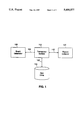
- FIG. 1 is a block diagram of a system including an event generator, a record collector, a disk drive, and a transaction system in accordance with the present invention.
- FIG. 2 is a block diagram of the transaction system shown in FIG. 1.
- FIG. 3 illustrates the internal organization of the disk drive shown in FIG. 1.
- FIG. 4 illustrates a message which is generated by the event generator.
- FIG. 5 shows the structure of the event table shown in FIG. 2 which is suitable for storing the relationship between events and transactions in accordance with the present invention.
- FIG. 6 shows the structure of the state table shown in FIG. 2 which is suitable for storing the state of events in accordance with the present invention.
- FIG. 7 shows an embodiment of a transaction system in accordance with the present invention in a telecommunications system.
- FIG. 1 illustrates a computer transaction system (TS) 110 which operates in conjunction with an event generator (EG) 100, a record collector (RC) 120, and a disk drive 130 to process transactions.
- the EG 100 is connected to the TS 110 by a communications line represented by line 105.
- the TS 110 is connected to the RC 120 by a communications line represented by line 115.
- a transaction is defined as a group of related events generated over time. When all related events are received by the TS 110, they are processed as a unit to produce a record for the transaction. Thus, during the lifetime of each transaction, a series of several events containing raw data related to the transaction are produced by the EG 100 and received by the TS 110. The first event in the series is called the initiating event, and the last one the terminating event. At the receipt of the terminating event, a record for the transaction is generated by the TS 110 from information contained in the events which are related to that transaction. The records for different transactions are sent by the TS 110 to the record collector 120 which then processes the records for other purposes.
- a nonvolatile storage medium such as the disk drive 130, is connected to the TS 110 to store information in the case of a failure of the TS 110.
- the connection between the TS 110 and the disk drive 130 is represented by line 125.
- the disk drive 130 is shown in more detail in FIG. 3, and will be described in more detail below.
- a high-capacity real-time transaction system such as TS 110 must format a large number of records from a large number of events with minimum latency.
- the primary function of the TS 110 is to receive events from the EG 100, assemble the events so that they are related to their transactions, format a record for a transaction when the terminating event for the transaction has been received, and send the records to the RC 120.
- the TS 110 communicates with the EG 100 and the RC 120 to confirm the transfer of data.
- the TS 110 will send a confirmation back to the EG 100 confirming the successful receipt of the events.
- the RC 120 will send a confirmation back to the TS 110 to confirm the successful receipt of the records.
- the timing of these confirmations are used in conjunction with the present data integrity technique, and will be described in further detail below.
- the transaction system 110 is shown in more detail in FIG. 2.
- the transaction system 110 contains a central processing unit 210 which controls the various functions of the TS 110 by execution of computer program code 270 stored in a memory unit 230.
- the CPU 210 is connected to an event buffer 220, the memory unit 230, and a record buffer 240.
- the CPU is connected to a cache memory 215 which contains a state table 260, an event table 250, and a block sequence number counter (BSN -- C) 280.
- the event table 250, the state table 260 and the BSN -- C 280 are stored in cache memory 215 to reduce system latency.
- these tables 250, 260, and 280 could also be stored in the memory unit 230.
- the EG 100 generates events and transmits them to the TS 110.
- a plurality of events are generally grouped together and transmitted as a message.
- a message 402 is shown in FIG. 4 and is made up of one or more variable-sized events, shown as E 1 , E 2 , . . . E n .
- Each of the events, E 1 , E 2 , . . . E n of a message 402 may be related to different transactions.
- the new events generated by the EG 100 are stored in the EG 100 instead of being transmitted to the TS 110.
- the stored events are sent to TS 110 from EG 100 such that the order of event generation is maintained.
- All messages received by the TS 110 from the EG 100 are initially stored in the event buffer 220 and a copy of each of the events is stored on the disk 130.
- the events are then processed and stored in the event table 250 as described in detail below.
- the event buffer 220 is then ready to receive new events from the EG 100.
- the disk 130 is organized into segments, shown in FIG. 3 as S 1 , S 2 , . . . S m .
- the size of each of these segments is the same size as the maximum size of a message received from the EG 100. For example, if the maximum size of a message is 16 kilobytes, then each disk segment is 16 kilobytes.
- a free disk segment must be located. The method of locating a free disk segment will be discussed below. At this point, for purposes of discussion, assume that segment S 1 has been identified as a free disk segment.
- segment S 1 is being used to store the message 402
- Each event E 1 , E 2 , . . . E n within message 402, along with the event's associated Event ID is then stored on the disk 130 in the assigned segment.
- the events E 1 , E 2 , . . . E n will be stored in segment S 1 as shown in FIG. 3.
- segment number has been stored on disk as part of the Event ID. However, this is not necessary in actual implementation because the segment number may be implied by the physical location of the event within the disk. As shown in FIG. 3, all Event ID's stored in segment S 1 contain a segment number of 1. Thus, in order to save disk space, the segment number would not be stored on the disk, but would be implied by an event's physical location.
- segment number list on disk (SN -- LD) 132 is used to record the order of the messages/events as they are received by the TS 110 from the EG 100.
- the SN -- LD 132 contains a list of the segment numbers of the disk segments which are assigned to the successive incoming messages from the EG 100. Therefore, in the present example, 1 is stored in the first location in the SN -- LD 132 to indicate that the first message is stored in segment S 1 .
- the segment number is stored in the SN -- LD 132, and the state table 260 and STD 134 have been updated (the updating of the state table 260 and the STD 134 is described in detail below), a confirmation is sent to the EG 100 from the TS 100 confirming that the message was received.
- a confirmation is sent to the EG 100 from the TS 100 confirming that the message was received.
- that segment number will be stored in the next location in the SN -- LD 132. This procedure continues for all messages received by the TS 110.
- the events are processed by the TS 110.
- Each of the events E 1 , E 2 , . . . E n of a message may be related to different transactions.
- the events along with their event IDs are stored in the event table 250 in the cache memory 215.
- the event table 250 is shown in more detail in FIG. 5.
- the event table 250 stores the events related to transactions which have been initiated but not yet terminated. For example, when an initiating event E 1 is received by the TS 110 for transaction T 1 an area 251 in the event table 250 is used to store the initiating event E 1 , its Event ID, and all subsequent events and Event IDs related to transaction T 1 .
- the events and Event IDs related to each of the transactions will be stored in the appropriate area of the event table 250. These events will be stored in the event table 250 until a terminating event is received and a record is formatted for the transaction.
- the creation of records for terminated transactions will be discussed below.
- the state table 260 in the cache memory 215 of the TS 110 keeps track of the state of each of the events stored in the event table 250 and on the disk 130. Periodically, the entire contents of the state table 260 is written into an area on disk 130 called the state table on disk (STD) 134 (FIG. 3) By writing the state table 260 to disk 130, the states of the various events can be recovered from the disk 130 in the event of a TS 110 failure.
- the state table 260 is shown in more detail in FIG. 6. Each row of the state table 260 represents a segment number of disk 130. Each column of the state table 260 represents the event number within the disk segment. Thus, there is a one-to-one mapping between entries in the state table 260 and events stored on the disk 130.
- each Event ID defines an entry in the state table 260, where the segment number represents the row and the event number represents the column in the state table 260.
- State table 260 entries contain the following values:
- 0 free, i.e., the event with the corresponding Event ID has been disposed, or no event has been assigned to the corresponding Event ID;
- Event ID has been assigned to an event and the event has not been disposed.
- An event is disposed, as the term is used herein, when its associated transaction has been terminated, a record has been formatted, the record has been sent to the RC 120, and an acknowledgment has been received by the TC 110 from the RC 120.
- a record has been formatted, the record has been sent to the RC 120, and an acknowledgment has been received by the TC 110 from the RC 120.
- TC 110 acknowledgment has been received by the TC 110 from the RC 120.
- a disk segment must be allocated each time a new message is received from the EG 100. It is essential that, upon a message arrival from the EG 100, a free disk segment can be located quickly so as not to hold up the acknowledgement to be returned to the EG 100. A disk segment is considered free and hence can be over-written by a new message only if it has not been written before, or all the events which had previously been written to that segment have been disposed. Note that in the latter case, the segment number of the segment with all events disposed will be removed from SN -- LD 132.
- a method of locating a free disk segment is to associate two counters in cache memory 215 with each disk segment.
- One counter is associated with the state table 260, and the other counter is associated with the STD 134.
- both counters are set to the total number of bytes used to store the events in the message.
- the counter associated with the state table 260 is decremented by the size of the event.
- the contents of the counter associated with the state table 260 replaces that of the counter associated with the STD 134.
- the counter associated with the STD 134 When the counter associated with the STD 134 has a zero value, the corresponding segment number is removed from the SN -- LD 132, and this signifies that the disk segment is free.
- the counters instead of counting the number of bytes used, the counters can be used to count the number of events that have not been disposed.
- each message such as message 402 arrives at the TS 110 from the EG 100 is as follows.
- the message 402 will arrive into the event buffer 220, which is a temporary storage area for the received messages.
- a free disk segment is located.
- Each event E 1 , E 2 , . . . E n in the message 402 is assigned an appropriate Event ID. These events, together with the assigned Event ID's, are written into the allocated free disk segment. As discussed above, these events are stored on the disk 130 in segment S 1 , as shown in FIG. 3.
- the state values for these Event ID's in the state table 260 are set to 1.
- the entries in state table 260 which are associated with events E 1 and E 2 are set to 1.
- event E 1 has an Event ID of ⁇ 1,1 ⁇ and event E 2 has an Event ID of ⁇ 1,2 ⁇ . Therefore, the entries in the state table 260 at ⁇ row 1 , column 1 ⁇ , and ⁇ row 1, column 2 ⁇ are set to 1 as shown in FIG. 6. The corresponding entries in STD 134 are also set to 1. Thus, upon the storage of events in the disk 130, the state values for the associated Event ID's in both the state table 260 and the STD 134 are set to one. Note that this is not the same as the periodic updating of the STD 134.
- event table 250 As a message, such as message 402, is received by the TS 110, the events contained in the message are processed sequentially. The events are written into the event table 250 and organized according to transaction. For example, assume event E 1 of message 402 is the initiating event for transaction T 2 . In such a case, event E 1 would be stored in the event table 250 in section 252 as shown in FIG. 5. If event E 2 of message 402 was also an event related to transaction T 2 , then it would also be stored in section 252 of event table 250 as shown. In this manner, the event table 250 keeps track of all the currently pending transactions, i.e., transactions for which an initiating event has been received but not a terminating event.
- the event buffer 220 When all events contained in a message are stored in the event table 250, the event buffer 220 is ready to receive another message. Upon receipt of a terminating event, a transaction has terminated and a record will be generated for the transaction. The events related to the terminated transaction are formatted into a record. The record is then ready to be sent to the RC 120. There may be transactions which are made up of only 1 event. These single event transactions are processed the same as multiple event transactions except that the initiating event and terminating event are the same. Also, single event transactions can be formatted into records immediately without the need to store the associated events in the event table 250.
- Formatted records are first sent to a record buffer 240, where they are stored for a certain time period.
- the records are sent to the RC 120 as a block.
- the RC 120 receives a block of records, it generates an acknowledgement and sends it to the TS 110.
- the state table 260 is updated to reflect that the events which were part of the terminated transactions have been disposed.
- all entries in the state table 260 corresponding to the Event IDs of the disposed events are set to 0.
- the STD 134 is not updated each time an event is disposed. Instead, the STD 134 is updated periodically to reflect the disposal of events. This is done by periodically saving the state table 260 to the STD 134.
- garbage collection process For transactions with long durations, their events will stay in both the event table 250 and the allocated disk segment for a long time. To minimize fragmentation of the disk space, some type of garbage collection process may need to be run periodically to collect these events together. For example, when the number of free disk segments drops below a certain threshold, the garbage collection process can be scheduled to run only during periods of low processor utilization.
- the garbage collection process may be of any suitable type which can be readily implemented by one skilled in the art.
- one choice for disk segment size is the maximum size of a message received by the TS 110. However, the smaller the segment size, the smaller the probability for a segment to contain the events of a long call, and therefore, the lesser the need for a garbage collection process to run. Thus, if under normal conditions, EG message sizes are much smaller than the maximum, then, the chosen segment size should be small to avoid fragmentation.
- any data lost as a result of a failure of the TS 110 can be reconstructed.
- the reconstruction procedure is described below.
- the STD 134 and the SN -- LD 132 are read from the disk 130.
- the STD 132 is used to reconstruct the state table 260 in cache memory 215.
- the SN -- LD 132 will contain an ordered list of segment numbers in which messages received from the EG 100 were stored prior to the failure.
- the first allocated disk segment is read from the SN -- LD 132 and the events and associated Event IDs are read from that disk segment.
- the corresponding entry in the state table 260, as reconstructed from the STD 132 is examined. If the entry contains a 0, it indicates that the event had been disposed prior to the failure, and thus there is no need to continue processing the event, and the event can be discarded.
- the state of an event in the state table 260 is not set to 0 until acknowledgement is received from the RC 120 that the record associated with the event has been received. Thus, any event with a state of 0 has been fully processed into a record and the record has been sent to and confirmed by the RC 120. If the entry in the state table 260 is a 1, then the corresponding event had not been disposed of prior to the failure, and the event is processed and placed in the corresponding location in the event table 250.
- the events are processed in the same way as they were processed when they were received by the TS 110 during normal processing.
- BSN block sequence number
- the BSN for the confirmed record block is stored in the block sequence number on disk (BSN -- D) 136.
- the current value contained in the BSN D 136 is stored in BSN -- OLD 138.
- the BSN -- D 136 is updated to contain the BSN of the most recently disposed of record block. In effect, each time a record block is disposed, the BSN -- D 136 is incremented by one.
- BSN-D 136 will contain the BSN of the last record block actually sent to and confirmed by the RC 120
- BSN-OLD 138 will contain the BSN of the last record block sent to and confirmed by the RC 120 as reflected in the STD 134.
- BSN -- C 280 is set to the value of BSN -- OLD 138 plus one.
- the above technique will remove all duplicate records generated as a result of the failure of the TS 110. Specifically, it will remove all duplicates generated for those records that are considered disposed by TS 110.
- one failure scenario is as follows.
- the TS 110 has made a transfer of record blocks to the RC 120.
- the RC 120 then returns an acknowledgement to the TS 110.
- the TS 110 fails just before it receives this acknowledgement.
- the record blocks have not yet been disposed.
- the BSN values of these record blocks will not be reflected in BSN -- D 136.
- the TS 110 will therefore not recognize them as duplicates. In this case, duplicate removal will need to be done by the RC 120 in the protocol between the TS 110 and RC 120.
- a transaction system in accordance with the present invention may be used in a telecommunications system in which telephone calls are processed, as shown in FIG. 7.
- Telephone calls are made from various telephone locations, 702.
- details about the call (such as source and destination number, call type, call duration, etc.) are generated by a telephone switching system 710.
- Each of the calls is a transaction and the details of each call are the events.
- the telephone switching system 710 generates events and sends them to the call detail recording system 720.
- the call detail recording system 720 processes the events related to each call, formats the events into records, and sends the records to a call detail record collector 730.
- a disk drive 740 is connected to the call detail recording system 720.
- the telephone switching system 710 operates as the EG 100
- the call detail recording system 720 operates as the TS 110
- the call detail record collector 730 operates as the RC 120, as described above in conjunction with FIGS. 1-6.
Abstract
Description
Claims (37)
Priority Applications (1)
| Application Number | Priority Date | Filing Date | Title |
|---|---|---|---|
| US08/166,481 US5450577A (en) | 1993-12-14 | 1993-12-14 | Zero-defect data integrity in high-capacity transaction systems |
Applications Claiming Priority (1)
| Application Number | Priority Date | Filing Date | Title |
|---|---|---|---|
| US08/166,481 US5450577A (en) | 1993-12-14 | 1993-12-14 | Zero-defect data integrity in high-capacity transaction systems |
Publications (1)
| Publication Number | Publication Date |
|---|---|
| US5450577A true US5450577A (en) | 1995-09-12 |
Family
ID=22603487
Family Applications (1)
| Application Number | Title | Priority Date | Filing Date |
|---|---|---|---|
| US08/166,481 Expired - Fee Related US5450577A (en) | 1993-12-14 | 1993-12-14 | Zero-defect data integrity in high-capacity transaction systems |
Country Status (1)
| Country | Link |
|---|---|
| US (1) | US5450577A (en) |
Cited By (6)
| Publication number | Priority date | Publication date | Assignee | Title |
|---|---|---|---|---|
| US6092066A (en) * | 1996-05-31 | 2000-07-18 | Emc Corporation | Method and apparatus for independent operation of a remote data facility |
| US6161198A (en) * | 1997-12-23 | 2000-12-12 | Unisys Corporation | System for providing transaction indivisibility in a transaction processing system upon recovery from a host processor failure by monitoring source message sequencing |
| US6502205B1 (en) | 1993-04-23 | 2002-12-31 | Emc Corporation | Asynchronous remote data mirroring system |
| US20040123183A1 (en) * | 2002-12-23 | 2004-06-24 | Ashutosh Tripathi | Method and apparatus for recovering from a failure in a distributed event notification system |
| US20050076276A1 (en) * | 2003-10-07 | 2005-04-07 | International Business Machines Corporation | System and method for defect projection in transaction management in a target computer environment |
| US20190243582A1 (en) * | 2017-06-20 | 2019-08-08 | Hitachi, Ltd. | Storage device and storage area management method |
Citations (5)
| Publication number | Priority date | Publication date | Assignee | Title |
|---|---|---|---|---|
| US5065311A (en) * | 1987-04-20 | 1991-11-12 | Hitachi, Ltd. | Distributed data base system of composite subsystem type, and method fault recovery for the system |
| US5175866A (en) * | 1987-06-03 | 1992-12-29 | Ericcson Ge Mobile Communications Inc. | Fail-soft architecture for public trunking system |
| US5201044A (en) * | 1990-04-16 | 1993-04-06 | International Business Machines Corporation | Data processing method for file status recovery includes providing a log file of atomic transactions that may span both volatile and non volatile memory |
| US5247664A (en) * | 1991-03-28 | 1993-09-21 | Amoco Corporation | Fault-tolerant distributed database system and method for the management of correctable subtransaction faults by the global transaction source node |
| US5317731A (en) * | 1991-02-25 | 1994-05-31 | International Business Machines Corporation | Intelligent page store for concurrent and consistent access to a database by a transaction processor and a query processor |
-
1993
- 1993-12-14 US US08/166,481 patent/US5450577A/en not_active Expired - Fee Related
Patent Citations (6)
| Publication number | Priority date | Publication date | Assignee | Title |
|---|---|---|---|---|
| US5065311A (en) * | 1987-04-20 | 1991-11-12 | Hitachi, Ltd. | Distributed data base system of composite subsystem type, and method fault recovery for the system |
| US5333314A (en) * | 1987-04-20 | 1994-07-26 | Hitachi, Ltd. | Distributed data base system of composite subsystem type, and method of fault recovery for the system |
| US5175866A (en) * | 1987-06-03 | 1992-12-29 | Ericcson Ge Mobile Communications Inc. | Fail-soft architecture for public trunking system |
| US5201044A (en) * | 1990-04-16 | 1993-04-06 | International Business Machines Corporation | Data processing method for file status recovery includes providing a log file of atomic transactions that may span both volatile and non volatile memory |
| US5317731A (en) * | 1991-02-25 | 1994-05-31 | International Business Machines Corporation | Intelligent page store for concurrent and consistent access to a database by a transaction processor and a query processor |
| US5247664A (en) * | 1991-03-28 | 1993-09-21 | Amoco Corporation | Fault-tolerant distributed database system and method for the management of correctable subtransaction faults by the global transaction source node |
Cited By (11)
| Publication number | Priority date | Publication date | Assignee | Title |
|---|---|---|---|---|
| US6502205B1 (en) | 1993-04-23 | 2002-12-31 | Emc Corporation | Asynchronous remote data mirroring system |
| US6625705B2 (en) | 1993-04-23 | 2003-09-23 | Emc Corporation | Remote data mirroring system having a service processor |
| US6647474B2 (en) | 1993-04-23 | 2003-11-11 | Emc Corporation | Remote data mirroring system using local and remote write pending indicators |
| US6092066A (en) * | 1996-05-31 | 2000-07-18 | Emc Corporation | Method and apparatus for independent operation of a remote data facility |
| US6161198A (en) * | 1997-12-23 | 2000-12-12 | Unisys Corporation | System for providing transaction indivisibility in a transaction processing system upon recovery from a host processor failure by monitoring source message sequencing |
| US20040123183A1 (en) * | 2002-12-23 | 2004-06-24 | Ashutosh Tripathi | Method and apparatus for recovering from a failure in a distributed event notification system |
| US20050076276A1 (en) * | 2003-10-07 | 2005-04-07 | International Business Machines Corporation | System and method for defect projection in transaction management in a target computer environment |
| US20190243582A1 (en) * | 2017-06-20 | 2019-08-08 | Hitachi, Ltd. | Storage device and storage area management method |
| CN110199265A (en) * | 2017-06-20 | 2019-09-03 | 株式会社日立制作所 | Storage device and storage area management method |
| US10846023B2 (en) * | 2017-06-20 | 2020-11-24 | Hitachi, Ltd. | Storage device and storage area management method for reducing garbage collection processing |
| CN110199265B (en) * | 2017-06-20 | 2022-11-01 | 株式会社日立制作所 | Storage device and storage area management method |
Similar Documents
| Publication | Publication Date | Title |
|---|---|---|
| US6477617B1 (en) | Method for performing atomic, concurrent read and write operations on multiple storage devices | |
| US7380158B2 (en) | Method and system for providing persistent storage of user data | |
| US5555371A (en) | Data backup copying with delayed directory updating and reduced numbers of DASD accesses at a back up site using a log structured array data storage | |
| US7742414B1 (en) | Lightweight indexing for fast retrieval of data from a flow-level compressed packet trace | |
| EP0623877B1 (en) | System and method for storing persistent and non-persistent queued data | |
| AU2004217278B2 (en) | Asynchronous mechanism and message pool | |
| JPH11184744A (en) | Message queuing system | |
| US7870421B2 (en) | Systems and methods for recovering memory | |
| US20050223163A1 (en) | Synchronous message queues | |
| US20010013103A1 (en) | Parity storage unit, in a disk array system, for generating updated parity data from received data records | |
| JPWO2004025475A1 (en) | Database reorganization system and database | |
| US6769027B1 (en) | System and method for using multi-headed queues for bookmarking in backup/recover scenarios | |
| US6859824B1 (en) | Storage system connected to a data network with data integrity | |
| US5450577A (en) | Zero-defect data integrity in high-capacity transaction systems | |
| US7113953B2 (en) | System and method for efficiently writing data from an in-memory database to a disk database | |
| CN113392132B (en) | Distributed caching method and system for IOT scene | |
| KR101499890B1 (en) | Low Latency Framework System | |
| CN114827300B (en) | Data reliable transmission system, control method, equipment and terminal for hardware guarantee | |
| JP4280306B2 (en) | Log-based data architecture for transaction message queuing systems | |
| US20220147486A1 (en) | System and method for managing timeseries data | |
| JPH0816881B2 (en) | Database update method | |
| CN111225169B (en) | Storage method and device for small video files | |
| GB2378536A (en) | A method of logging message activity | |
| CN116483886B (en) | Method for inquiring OLAP by combining KV storage engine and time sequence storage engine | |
| CN110727402B (en) | High-speed FC data real-time receiving and frame loss-free storage method |
Legal Events
| Date | Code | Title | Description |
|---|---|---|---|
| AS | Assignment |
Owner name: AMERICAN TELEPHONE AND TELEGRAPH COMPANY, NEW YORK Free format text: ASSIGNMENT OF ASSIGNORS INTEREST;ASSIGNORS:LAI, WAI S.;LAPADULA, CHARLES A.;REEL/FRAME:006821/0432 Effective date: 19931201 |
|
| AS | Assignment |
Owner name: AT&T CORP., NEW YORK Free format text: ASSIGNMENT OF ASSIGNORS INTEREST;ASSIGNOR:AMERICAN TELELPHONE AND TELEGRAPH COMPANY;REEL/FRAME:007527/0274 Effective date: 19940420 Owner name: AT&T IPM CORP., FLORIDA Free format text: ASSIGNMENT OF ASSIGNORS INTEREST;ASSIGNOR:AT&T CORP.;REEL/FRAME:007528/0038 Effective date: 19950523 |
|
| FEPP | Fee payment procedure |
Free format text: PAYOR NUMBER ASSIGNED (ORIGINAL EVENT CODE: ASPN); ENTITY STATUS OF PATENT OWNER: LARGE ENTITY |
|
| FPAY | Fee payment |
Year of fee payment: 4 |
|
| REMI | Maintenance fee reminder mailed | ||
| LAPS | Lapse for failure to pay maintenance fees | ||
| STCH | Information on status: patent discontinuation |
Free format text: PATENT EXPIRED DUE TO NONPAYMENT OF MAINTENANCE FEES UNDER 37 CFR 1.362 |
|
| FP | Lapsed due to failure to pay maintenance fee |
Effective date: 20030912 |